Configure Option 125 on a Server to Allow Dynamic Host Configuration Protocol (DHCP) Auto Image Updates on a Switch
Objective
Scenario:
Managing multiple or stacked switches in the network could be very challenging to maintain, especially if you have to add a new switch to the network, apply new configuration settings, or update each switch to its latest image version. You would want to find a way to allow the switches to automatically update their own images.
If you have enabled and configured the Dynamic Host Configuration Protocol (DHCP) Auto Configuration and Auto Image Update features to automatically update the firmware and configurations on a switch that is connected to a server which serves as a DHCP server. However, after configuring DHCP-based auto update, the switch did not download and apply the latest image.
Solution:
Enabling the DHCP image upgrade features to download both a new image and a new configuration file to one or more switches in the network is very helpful in making sure that each new switch added to the network receives the same image and configuration. These features function properly only when the DHCP server is configured to assign the host IP address dynamically. By default, the switch is enabled as a DHCP client when the Auto Configuration feature is enabled. If Image Auto Update is enabled, the flash image is downloaded and updated. If the new configuration is downloaded to a switch that already has a configuration, the downloaded configuration is appended to the configuration file stored on the switch.
Auto image download is done using an indirect image file. The indirect Image file is a text file that contains the path to the actual image file which is uploaded on a TFTP or SCP server. To provide the indirect image file name, Option 125 needs to be configured with the following parameters on the DHCP server:
- enterprise-number (4 octets) — Hex (0000.0009)
- sub-option-code (1 octet) — Hex (05)
- File name that points to the indirect image (ASCII to Hex)
This article provides instructions on how to configure Option 125 on the server to relay DHCP addresses correctly and make auto image update work on the switch.
Note: Before you proceed, you can verify if you have correctly configured the DHCP Image Upgrade Settings on your switch. For step-by-step instructions, click here.
Applicable Devices
- Sx200 Series
- Sx250 Series
- Sx300 Series
- Sx350 Series
- SG350X Series
- Sx500 Series
- Sx550X Series
Configure Option 125
Add Option 125 in your Server
Important: Make sure that there is an active DHCP server running in your Linux or Windows server.
Note: In this scenario, Windows Server 2012 R2 is used.
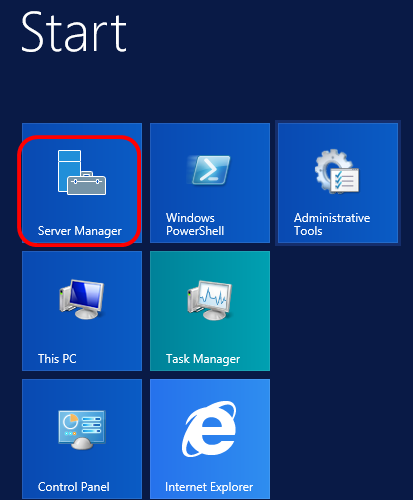
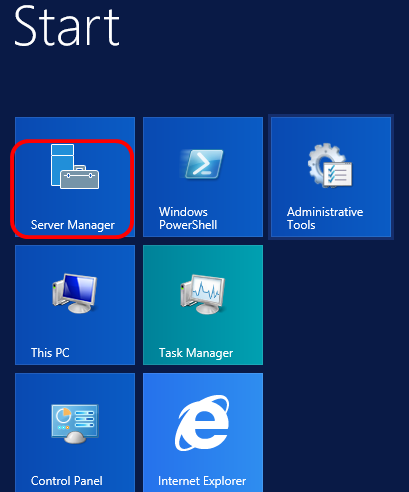
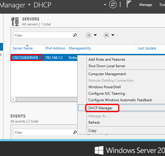
Step 1. Click Start > Server Manager.
Step 2. Right-click on the server name then click DHCP Manager.
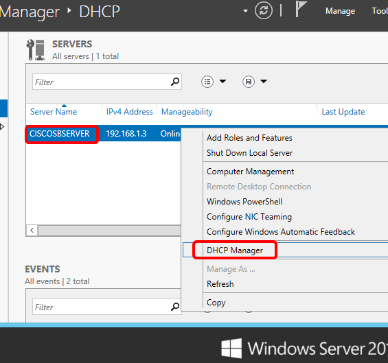
Note: In this example, CISCOSBSERVER is the server name.
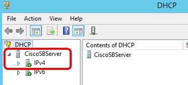
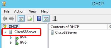
Step 3. Click the collapse button of the server name, and then click the collapse button of IPv4 to show available options.
Note: Option 125 works on IPv4 addressing only. If you want to configure DHCP Auto Image Upgrade settings on IPv6 address scope, configure Option 60 instead.
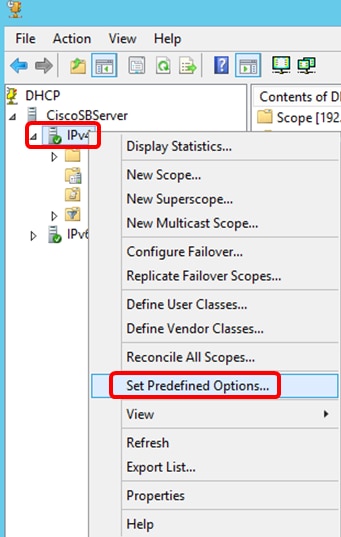
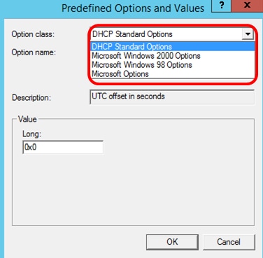
Step 4. Right-click on IPv4, and then click Set Predefined Options.
Step 5. Click DHCP Standard Options in the Option class drop-down list.
Step 6. Scroll down the Option name drop-down list to search for the option that starts with 125.
Note: By default, Option 125 is not available. If you have pre-configured Option 125, you can skip to Configure Option 125 Settings Through Netsh.
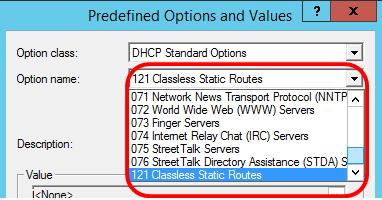
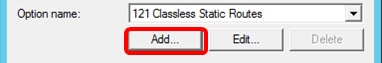
Step 7. If verified that Option 125 is not on the list, click Add.
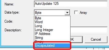
Step 8. Enter the option name in the Name field.
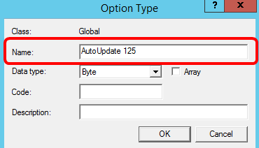
Note: In this example, AutoUpdate 125 is used.
Step 9. Click Encapsulated from the Data type drop-down list.
Step 10. Enter 125 in the Code field. This code refers to the Option number indicator found at the beginning of the Option name as shown in Step 6.
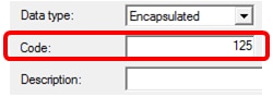
Note: This code is used to create the Option 125.
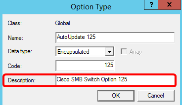
Step 11. Enter the option description in the Description field and then, click OK.
Note: Cisco SMB Switch Option 125 is used as an example.
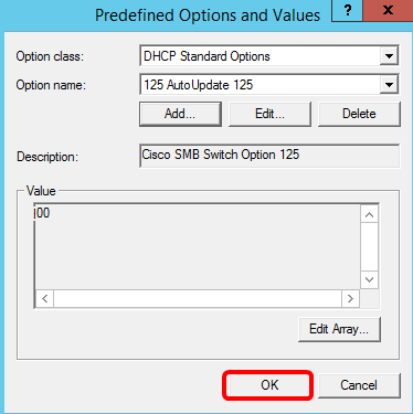
Step 12. Click OK in the Predefined Options and Values window.
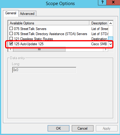
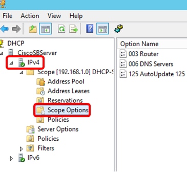
Step 13. (Optional) To verify the newly added option, choose Scope Options > Configure Options under the IP version that you have configured.
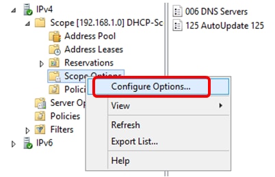
The Option 125 should now show in the list of Scope Options.
Configure Option 125 Settings Through Netsh
The proposed configuration method here uses netsh for configuring Option 125. This will allow you to run several netsh DHCP commands in the command prompt to modify the network configuration settings.
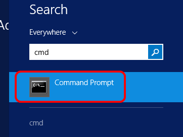
Step 1. Click Start then enter cmd in the Search box.
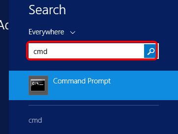
Step 2. Once the Command Prompt logo appears, click to launch.
Step 3. Change your current directory to Drive C:\ by entering the following:

Note: In this example, C:\Users\Administrator is the current directory. This may vary depending on the user name and directory on your computer.
Step 4. Access the netsh command-line utility by entering the following:

Step 5. Change to the DHCP context by entering the following:

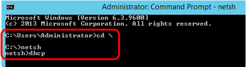
Step 6. Shift from DHCP context to the server by entering the following:

Step 7. Enter the command scope and IP address to shift from the server context to the specified DHCP scope address and then press the Enter key. The prompt should display that current scope context has been changed.

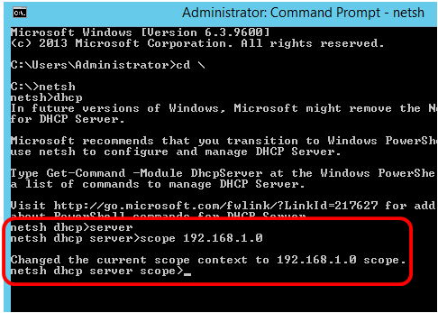
Note: In this example, the scope used is 192.168.1.0.
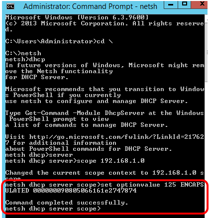
Step 8. Enter the command set optionvalue 125 ENCAPSULATED and the Option 125 code. After pressing Enter on your keyboard, the prompt below should display that the command has been successfully completed.

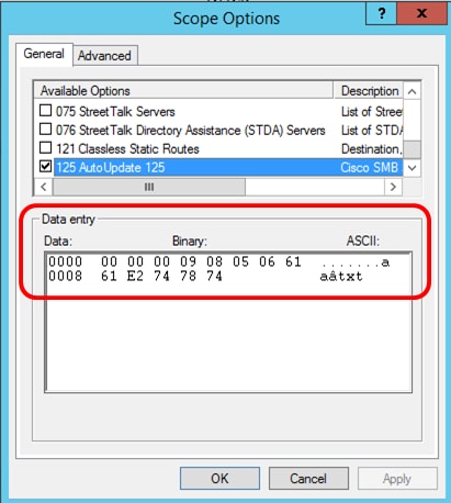
Note: In this example, 000000090805066161e2747874 is the code number used.
Option 125 Code Interpretation:
- 00-00-00-09 — Enterprise Number (Cisco Value)
- 08 — Option 125 Data Len
- 05 — Sub Option Code
- 06 — Sub Option Length
- 61-61-2E-74-78-74 — Sub Option Data ( aa.txt – ASCII to HEX conversion)
You should now have configured the Option 125 settings through netsh.
Verify Option 125 in DHCP Server
Step 1. Click Start > Server Manager.
Step 2. Right-click on the server name then click DHCP Manager.
Note: In this example, CISCOSBSERVER is the server name.
Step 3. Click the collapse button of the server name to show available IP versions.
Step 4. Click the collapse button of the IP version, then click Scope Options.
Note: In this example, IPv4 is chosen.
Step 5. Right-click on the configured Option 125, then click Properties.
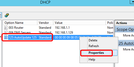
The configured Option 125 Scope Options page should display the Data, Binary, and ASCII codes in the Data entry area.
The Option 125 has now been successfully configured on your Windows Server.
Revision History
| Revision | Publish Date | Comments |
|---|---|---|
|
1.0 |
13-Dec-2018 |
Initial Release |
- Remove From My Forums
-
Question
-
Maybe some one can help me? i need some information how to set up DHCP option 125 on server 2008 R2 x64. I can`t find any
info about it.Thank You
Answers
-
Hi Javcia,
Thanks for posting here.Base on my knowledge this is a Vendor Specific DHCP option , so are we using windows DHCP server to co-work with other devices? VOIP maybe?
Technically we can add Vendor Specific DHCP option by using command ‘netsh dhcp server scope ipaddress set optionvalue 125
<code>’ to set the value.Thanks.
Tiger Li
Tiger Li
TechNet Community Support

-
Marked as answer by
Tuesday, August 28, 2012 8:32 AM
-
Marked as answer by
-
Hi Javcia,
Thanks for update.
May I know what VOIP devices are we going to deploy ?
At this moment , I think we’d better to consult with the support service of that VIOP device in order to get the code for corresponding OS . After that we can set vivso into Windows DHCP service.
Thanks.
Tiger Li
Tiger Li
TechNet Community Support
-
Marked as answer by
Tiger LiMicrosoft employee
Tuesday, August 28, 2012 8:32 AM
-
Marked as answer by
Networking Requirements
On the network shown in Figure 1-566, to allow the CE and PEs to communicate, configure EVPN. DHCP needs to be deployed so that the DHCP server can assign an IP address to the DHCP client. PE1 and PE2 function as gateways, and DHCP relay needs to be deployed on them. PE3 is connected to the DHCP server.
Figure 1-566 EVPN networking
Interfaces 1 through 3 in this example represent GE 0/1/0, GE 0/2/0, and GE 0/3/0, respectively.
Table 1-266 Interface IP addresses
|
Device |
Interface |
IP Address |
|---|---|---|
|
PE1 |
GE 0/2/0 |
192.168.2.1/24 |
|
GE 0/3/0 |
192.168.1.2/24 |
|
|
Loopback 1 |
12.1.1.1/32 |
|
|
LoopBack2 |
14.1.1.1/32 |
|
|
PE2 |
GE 0/2/0 |
192.168.2.2/24 |
|
GE 0/3/0 |
172.16.1.1/24 |
|
|
Loopback 1 |
13.1.1.1/32 |
|
|
LoopBack2 |
15.1.1.1/32 |
|
|
PE3 |
GE 0/1/0 |
192.168.1.1/24 |
|
GE 0/2/0 |
172.16.1.2/24 |
|
|
GE 0/3/0 |
30.1.1.1/24 |
|
|
Loopback 1 |
11.1.1.1/32 |
Configuration Roadmap
The configuration roadmap is as follows:
- Assign an IP address to each interface on the CE and PEs.
-
Configure an IGP on the backbone network to allow the PEs to communicate.
-
Configure basic MPLS functions, enable MPLS LDP, and establish LDP LSPs on the backbone network.
-
Configure an EVPN instance on each PE.
- Bind the EVPN instance to a BD on each PE.
- Configure a VPN instance on each PE, and bind the PE’s loopback interface to the VPN instance to import loopback routes from the CE.
- Configure a source address on each PE.
-
Configure an Eth-Trunk interface for connecting PE1 and PE2 to the CE.
-
Configure an ESI for the Eth-Trunk interface on PE1 and PE2.
- Configure a service access point on PE1 and PE2.
- Enable the BGP-EVPN address family, and configure peers on each PE.
- Enable EVPN to generate and advertise IP prefix routes and IRB routes in a VPN instance.
- Enable the VPN instance to advertise IP routes to the EVPN instance on each PE.
-
Establish a BGP EVPN peer relationship between the PEs.
-
Configure the CE, PE1, and PE2 to communicate.
- Configure DHCP relay on PE1 and PE2.
Data Preparation
To complete the configuration, you need the following data:
-
EVPN instance name: evpna
-
EVPN instance evpna‘s RD and RT on each PE: 1:1
Procedure
- Assign an IP address to each interface according to Figure 1-566. For configuration details, see Configuration Files in this section.
Using the local loopback interface address of each PE as the source address is recommended.
- Configure an IGP on the backbone network to allow the PEs to communicate. OSPF is used as an IGP in this example.
# Configure PE1.
[~PE1] ospf 1[*PE1-ospf-1] area 0[*PE1-ospf-1-area-0.0.0.0] network 12.1.1.1 0.0.0.0[*PE1-ospf-1-area-0.0.0.0] network 20.1.1.1 0.0.0.0[*PE1-ospf-1-area-0.0.0.0] network 192.168.1.0 0.0.0.255
[*PE1-ospf-1-area-0.0.0.0] network 192.168.2.0 0.0.0.255
[*PE1-ospf-1-area-0.0.0.0] commit[~PE1-ospf-1-area-0.0.0.0] quit[~PE1-ospf-1] quit# Configure PE2.
[~PE2] ospf 1[*PE2-ospf-1] area 0[*PE2-ospf-1-area-0.0.0.0] network 13.1.1.1 0.0.0.0[*PE2-ospf-1-area-0.0.0.0] network 20.1.1.1 0.0.0.0[*PE2-ospf-1-area-0.0.0.0] network 172.16.1.0 0.0.0.255
[*PE2-ospf-1-area-0.0.0.0] network 192.168.2.0 0.0.0.255
[*PE2-ospf-1-area-0.0.0.0] commit[~PE2-ospf-1-area-0.0.0.0] quit[~PE2-ospf-1] quit# Configure PE3.
[~PE3] ospf 1[*PE3-ospf-1] area 0[*PE3-ospf-1-area-0.0.0.0] network 11.1.1.1 0.0.0.0[*PE3-ospf-1-area-0.0.0.0] network 192.168.1.0 0.0.0.255[*PE3-ospf-1-area-0.0.0.0] network 172.16.1.0 0.0.0.255
[*PE3-ospf-1-area-0.0.0.0] commit[~PE3-ospf-1-area-0.0.0.0] quit[~PE3-ospf-1] quit - Configure basic MPLS functions, enable MPLS LDP, and establish LDP LSPs on the backbone network.
# Configure PE1.
[~PE1] mpls lsr-id 12.1.1.1[*PE1] mpls[*PE1-mpls] quit[*PE1] mpls ldp[*PE1-mpls-ldp] quit[*PE1] interface GigabitEthernet 0/2/0
[*PE1-GigabitEthernet0/2/0] mpls
[*PE1-GigabitEthernet0/2/0] mpls ldp
[*PE1-GigabitEthernet0/2/0] commit
[~PE1-GigabitEthernet0/2/0] quit
[*PE1] interface GigabitEthernet 0/3/0[*PE1-GigabitEthernet0/3/0] mpls[*PE1-GigabitEthernet0/3/0] mpls ldp[*PE1-GigabitEthernet0/3/0] commit[~PE1-GigabitEthernet0/3/0] quit# Configure PE2.
[~PE2] mpls lsr-id 13.1.1.1[*PE2] mpls[*PE2-mpls] quit[*PE2] mpls ldp[*PE2-mpls-ldp] quit[*PE2] interface GigabitEthernet 0/2/0
[*PE2-GigabitEthernet0/2/0] mpls
[*PE2-GigabitEthernet0/2/0] mpls ldp
[*PE2-GigabitEthernet0/2/0] commit
[~PE2-GigabitEthernet0/2/0] quit
[*PE2] interface GigabitEthernet 0/3/0[*PE2-GigabitEthernet0/3/0] mpls[*PE2-GigabitEthernet0/3/0] mpls ldp[*PE2-GigabitEthernet0/3/0] commit[~PE2-GigabitEthernet0/3/0] quit# Configure PE3.
[~PE3] mpls lsr-id 11.1.1.1[*PE3] mpls[*PE3-mpls] quit[*PE3] mpls ldp[*PE3-mpls-ldp] quit[*PE3] interface GigabitEthernet 0/1/0
[*PE3-GigabitEthernet0/1/0] mpls
[*PE3-GigabitEthernet0/1/0] mpls ldp
[*PE3-GigabitEthernet0/1/0] quit
[*PE3] interface GigabitEthernet 0/2/0
[*PE3-GigabitEthernet0/2/0] mpls
[*PE3-GigabitEthernet0/2/0] mpls ldp
[*PE3-GigabitEthernet0/2/0] quit
- Configure an EVPN instance on each PE.
# Configure PE1.
[~PE1] evpn vpn-instance evpna bd-mode[*PE1-evpn-instance-evpna] route-distinguisher 1:1[*PE1-evpn-instance-evpna] vpn-target 1:1[*PE1-evpn-instance-evpna] quit[*PE1] commit# Configure PE2.
[~PE2] evpn vpn-instance evpna bd-mode[*PE2-evpn-instance-evpna] route-distinguisher 1:1[*PE2-evpn-instance-evpna] vpn-target 1:1[*PE2-evpn-instance-evpna] quit[*PE2] commit# Configure PE3.
[~PE3] evpn vpn-instance evpna bd-mode[*PE3-evpn-instance-evpna] route-distinguisher 1:1[*PE3-evpn-instance-evpna] vpn-target 1:1[*PE3-evpn-instance-evpna] quit[*PE3] commit - Bind the EVPN instance to a BD on each PE.
# Configure PE1.
[~PE1] bridge-domain 1
[*PE1-bd1] evpn binding vpn-instance evpna
[*PE1-bd1] quit
[*PE1] commit
# Configure PE2.
[~PE2] bridge-domain 1
[*PE2-bd1] evpn binding vpn-instance evpna
[*PE2-bd1] quit
[*PE2] commit
# Configure PE3.
[~PE3] bridge-domain 1
[*PE3-bd1] evpn binding vpn-instance evpna
[*PE3-bd1] quit
[*PE3] commit
- Configure a VPN instance on each PE, and bind the PE’s loopback interface to the VPN instance to import loopback routes from the CE.
# Configure PE1.
[~PE1] ip vpn-instance vpna
[*PE1-vpn-instance-vpna] ipv4-family
[*PE1-vpn-instance-vpna-af-ipv4] route-distinguisher 100:1
[*PE1-vpn-instance-vpna-af-ipv4] vpn-target 100:1 export-extcommunity
[*PE1-vpn-instance-vpna-af-ipv4] vpn-target 100:1 export-extcommunity evpn
[*PE1-vpn-instance-vpna-af-ipv4] vpn-target 100:1 import-extcommunity
[*PE1-vpn-instance-vpna-af-ipv4] vpn-target 100:1 import-extcommunity evpn
[*PE1-vpn-instance-vpna-af-ipv4] quit
[*PE1-vpn-instance-vpna] quit
[*PE1] interface LoopBack2
[*PE1-LoopBack2] ip binding vpn-instance vpna
[*PE1-LoopBack2] ip address 14.1.1.1 255.255.255.255
[*PE1-LoopBack2] commit
[*PE1-LoopBack2] quit
[*PE1] commit
The configurations of PE2 and PE3 are similar to the configuration of PE1.
- Configure a source address on each PE.
# Configure PE1.
[~PE1] evpn source-address 12.1.1.1[*PE1] evpn
[*PE1-evpn] vlan-extend private enable
[*PE1-evpn] vlan-extend redirect enable
[*PE1-evpn] local-remote frr enable
[*PE1-evpn] quit
[*PE1] commit# Configure PE2.
[~PE2] evpn source-address 13.1.1.1[*PE2] evpn
[*PE2-evpn] vlan-extend private enable
[*PE2-evpn] vlan-extend redirect enable
[*PE2-evpn] local-remote frr enable
[*PE2-evpn] quit
[*PE2] commit# Configure PE3.
[~PE3] evpn source-address 11.1.1.1[*PE3] evpn
[*PE3-evpn] vlan-extend private enable
[*PE3-evpn] vlan-extend redirect enable
[*PE3-evpn] local-remote frr enable
[*PE3-evpn] quit
[*PE3] commit - Configure an Eth-Trunk interface for connecting PE1 and PE2 to the CE.
# Configure PE1.
[~PE1] lacp e-trunk system-id 0001-0001-0001[*PE1] e-trunk 1
[*PE1-e-trunk-1] priority 50
[*PE1-e-trunk-1] peer-address 13.1.1.1 source-address 12.1.1.1[*PE1-e-trunk-1] quit[*PE1] interface eth-trunk 1[*PE1-Eth-Trunk1] mode lacp-static
[*PE1-Eth-Trunk1] e-trunk 1[*PE1-Eth-Trunk1] e-trunk mode force-master[*PE1-Eth-Trunk1] quit[*PE1] interface GigabitEthernet 0/1/0
[*PE1-GigabitEthernet0/1/0] eth-trunk 1
[*PE1-GigabitEthernet0/1/0] quit
[*PE1] commit# Configure PE2.
[~PE2] lacp e-trunk system-id 0001-0001-0001[*PE2] e-trunk 1[*PE2-e-trunk-1] priority 10[*PE2-e-trunk-1] peer-address 12.1.1.1 source-address 13.1.1.1[*PE2-e-trunk-1] quit[*PE2] interface eth-trunk 1[*PE2-Eth-Trunk1] mode lacp-static[*PE2-Eth-Trunk1] e-trunk 1[*PE2-Eth-Trunk1] e-trunk mode force-master[*PE2-Eth-Trunk1] quit[*PE2] interface GigabitEthernet 0/2/0
[*PE2-GigabitEthernet0/2/0] eth-trunk 1
[*PE2-GigabitEthernet0/2/0] quit
[*PE2] commit# Configure the CE.
[~CE] interface eth-trunk 1[*CE-Eth-Trunk1] mode lacp-static[*CE-Eth-Trunk1] quit[*CE] interface Ethernet 0/1/0
[*CE-Ethernet0/1/0] eth-trunk 1
[*CE-Ethernet0/1/0] quit
[*CE] commit[*CE] interface Ethernet 0/2/0
[*CE-Ethernet0/2/0] eth-trunk 1
[*CE-Ethernet0/2/0] quit
[*CE] commit - Configure an ESI for the Eth-Trunk interface on PE1 and PE2.
# Configure PE1.
[~PE1] interface eth-trunk 1[*PE1-Eth-Trunk1] esi 0000.0000.0000.0000.1111[*PE1-Eth-Trunk1] quit[*PE1] commit# Configure PE2.
[~PE2] interface eth-trunk 1[*PE2-Eth-Trunk1] esi 0000.0000.0000.0000.1111[*PE2-Eth-Trunk1] quit[*PE2] commit - Configure a service access point on PE1 and PE2.
# Configure PE1.
[~PE1] interface Eth-Trunk1.1 mode l2[~PE1-Eth-trunk1.1] encapsulation dot1q vid 100[*PE1-Eth-trunk1.1] rewrite pop single
[*PE1-Eth-trunk1.1] bridge-domain 1
[*PE1-Eth-trunk1.1] quit
[*PE1] commit
# Configure PE2.
[~PE2] interface Eth-Trunk1.1 mode l2[~PE2-Eth-trunk1.1] encapsulation dot1q vid 100[*PE2-Eth-trunk1.1] rewrite pop single
[*PE2-Eth-trunk1.1] bridge-domain 1
[*PE2-Eth-trunk1.1] quit
[*PE2] commit
- Enable the BGP-EVPN address family, and configure peers on each PE.
# Configure PE1.
[~PE1] bgp 100
[*PE1-bgp] l2vpn-family evpn
[*PE1-bgp-af-evpn] peer 11.1.1.1 enable
[*PE1-bgp-af-evpn] peer 11.1.1.1 advertise irb
[*PE1-bgp-af-evpn] peer 13.1.1.1 enable
[*PE1-bgp-af-evpn] peer 13.1.1.1 advertise irb
[*PE1-bgp-af-evpn] quit
[*PE1] commit
# Configure PE2.
[~PE2] bgp 100
[*PE2-bgp] l2vpn-family evpn
[*PE2-bgp-af-evpn] peer 11.1.1.1 enable
[*PE2-bgp-af-evpn] peer 11.1.1.1 advertise irb
[*PE2-bgp-af-evpn] peer 12.1.1.1 enable
[*PE2-bgp-af-evpn] peer 12.1.1.1 advertise irb
[*PE2-bgp-af-evpn] quit
[*PE2] commit
# Configure PE3.
[~PE3] bgp 100
[*PE3-bgp] l2vpn-family evpn
[*PE3-bgp-af-evpn] peer 12.1.1.1 enable
[*PE3-bgp-af-evpn] peer 12.1.1.1 advertise irb
[*PE3-bgp-af-evpn] peer 13.1.1.1 enable
[*PE3-bgp-af-evpn] peer 13.1.1.1 advertise irb
[*PE3-bgp-af-evpn] quit
[*PE3] commit
- Enable EVPN to generate and advertise IP prefix routes and IRB routes in a VPN instance.
# Configure PE1.
[~PE1] ip vpn-instance vpna
[~PE1-vpn-instance-vpna] ipv4-family
[~PE1-vpn-instance-vpna-af-ipv4] evpn mpls routing-enable
[*PE1-vpn-instance-vpna-af-ipv4] quit
[*PE1] commit
# Configure PE2.
[~PE2] ip vpn-instance vpna
[~PE2-vpn-instance-vpna] ipv4-family
[~PE2-vpn-instance-vpna-af-ipv4] evpn mpls routing-enable
[*PE2-vpn-instance-vpna-af-ipv4] quit
[*PE2] commit
# Configure PE3.
[~PE3] ip vpn-instance vpna
[~PE3-vpn-instance-vpna] ipv4-family
[~PE3-vpn-instance-vpna-af-ipv4] evpn mpls routing-enable
[*PE3-vpn-instance-vpna-af-ipv4] quit
[*PE3] commit
- Enable the VPN instance to advertise IP routes to the EVPN instance on each PE.
# Configure PE1.
[~PE1] bgp 100
[*PE1-bgp] ipv4-family vpn-instance vpna
[*PE1-bgp-vpna] import-route direct
[*PE1-bgp-vpna] advertise l2vpn evpn
[*PE1-bgp-vpna] quit
[*PE1] commit
# Configure PE2.
[~PE2] bgp 100
[*PE2-bgp] ipv4-family vpn-instance vpna
[*PE2-bgp-vpna] import-route direct
[*PE2-bgp-vpna] advertise l2vpn evpn
[*PE2-bgp-vpna] quit
[*PE2] commit
# Configure PE3.
[~PE3] bgp 100
[*PE3-bgp] ipv4-family vpn-instance vpna
[*PE3-bgp-vpna] import-route direct
[*PE3-bgp-vpna] advertise l2vpn evpn
[*PE3-bgp-vpna] quit
[*PE3] commit
- Establish a BGP EVPN peer relationship between the PEs.
# Configure PE1.
[~PE1] bgp 100[*PE1-bgp] peer 11.1.1.1 as-number 100[*PE1-bgp] peer 11.1.1.1 connect-interface loopback 1[*PE1-bgp] peer 13.1.1.1 as-number 100
[*PE1-bgp] peer 13.1.1.1 connect-interface loopback 1
[*PE1-bgp] peer 192.168.1.1 as-number 100[*PE1-bgp] peer 192.168.2.2 as-number 100
[*PE1-bgp] quit[*PE1] commit# Configure PE2.
[~PE2] bgp 100[*PE2-bgp] peer 11.1.1.1 as-number 100[*PE2-bgp] peer 11.1.1.1 connect-interface loopback 1[*PE2-bgp] peer 12.1.1.1 as-number 100
[*PE2-bgp] peer 12.1.1.1 connect-interface loopback 1
[*PE2-bgp] peer 172.16.1.2 as-number 100[*PE2-bgp] peer 192.168.2.1 as-number 100
[*PE2-bgp] quit[*PE2] commit# Configure PE3.
[~PE3] bgp 100[*PE3-bgp] peer 12.1.1.1 as-number 100[*PE3-bgp] peer 12.1.1.1 connect-interface loopback 1[*PE3-bgp] peer 13.1.1.1 as-number 100[*PE3-bgp] peer 13.1.1.1 connect-interface loopback 1[*PE3-bgp] peer 192.168.1.2 as-number 100[*PE3-bgp] peer 172.16.1.1 as-number 100[*PE3-bgp] quit[*PE3] commit - Configure the CE, PE1, and PE2 to communicate.
# Configure the CE.
[~CE] vlan batch 100[*CE] interface Eth-Trunk1[*CE-Eth-Trunk20] portswitch[*CE-Eth-Trunk20] port link-type trunk[*CE-Eth-Trunk20] port trunk allow-pass vlan 100[*CE-Eth-Trunk20] quit[*CE] interface ethernet0/3/0
[*CE-Ethernet0/3/0] portswitch
[*CE-Ethernet0/3/0] port link-type trunk
[*CE-Ethernet0/3/0] port trunk allow-pass vlan 100
[*CE-Ethernet0/3/0] quit
[*CE] commit# Configure PE1.
[~PE1] vlan batch 100[*PE1] interface GigabitEthernet0/1/0
[*PE1-GigabitEthernet0/1/0] eth-trunk 1
[*PE1-GigabitEthernet0/1/0] quit
[*PE1] commit# Configure PE2.
[~PE2] vlan batch 100[*PE2] interface GigabitEthernet0/1/0
[*PE2-GigabitEthernet0/1/0] eth-trunk 1
[*PE2-GigabitEthernet0/1/0] quit
[*PE2] commit - Configure DHCP relay on PE1 and PE2.
# Configure PE1.
[~PE1] interface Vbdif 1
[*PE1-Vbdif1] ip binding vpn-instance vpna
[*PE1-Vbdif1] ip address 10.1.1.1 255.255.255.0
[*PE1-Vbdif1] arp broadcast-detect enable
[*PE1-Vbdif1] arp expire-time 86400
[*PE1-Vbdif1] dhcp select relay
[*PE1-Vbdif1] ip relay address 30.1.1.2
[*PE1-Vbdif1] ip relay giaddr 10.1.1.1
[*PE1-Vbdif1] dhcp option82 vendor-specific insert enable
[*PE1-Vbdif1] dhcp option82 vendor-specific format vendor-sub-option 1 source-ip-address 14.1.1.1
[*PE1-Vbdif1] anycast-gateway enable
[*PE1-Vbdif1] arp collect host enable
[*PE1-Vbdif1] quit
[*PE1] commit
# Configure PE2.
[~PE2] interface Vbdif 1
[*PE2-Vbdif1] ip binding vpn-instance vpna
[*PE2-Vbdif1] ip address 10.1.1.1 255.255.255.0
[*PE2-Vbdif1] arp expire-time 86400
[*PE2-Vbdif1] dhcp select relay
[*PE2-Vbdif1] ip relay address 30.1.1.2
[*PE2-Vbdif1] ip relay giaddr 10.1.1.1
[*PE2-Vbdif1] dhcp option82 vendor-specific insert enable
[*PE2-Vbdif1] dhcp option82 vendor-specific format vendor-sub-option 1 source-ip-address 15.1.1.1
[*PE2-Vbdif1] anycast-gateway enable
[*PE2-Vbdif1] arp collect host enable
[*PE2-Vbdif1] quit
[*PE2] commit
- Verify the configuration.
# Run the display dhcp relay address command on PE1 and PE2 to check the DHCP relay configuration on VBDIF 1. The following example uses the command output on PE1.
[PE1] display dhcp relay address interface Vbdif 1
    **  Vbdif1 DHCP Relay Address  **
 Dhcp Option          Relay Agent IP       Server IP
 *                    10.1.1.1             30.1.1.2
The configuration succeeds if the DHCP client obtains an IP address from the DHCP server through the DHCP relay-enabled gateway and goes online successfully.
Configuration Files
-
PE1 configuration file
#
sysname PE1
#
vlan batch 100
#
lacp e-trunk system-id 0001-0001-0001
#
evpn
 vlan-extend private enable
 vlan-extend redirect enable
 local-remote frr enable
 #
 mac-duplication
#
evpn vpn-instance evpna bd-mode
 route-distinguisher 1:1
 vpn-target 1:1 export-extcommunity
 vpn-target 1:1 import-extcommunity
#
ip vpn-instance vpna
 ipv4-family
  route-distinguisher 100:1
  apply-label per-instance
  vpn-target 100:1 export-extcommunity
  vpn-target 100:1 export-extcommunity evpn
  vpn-target 100:1 import-extcommunity
  vpn-target 100:1 import-extcommunity evpn
  evpn mpls routing-enable
#
mpls lsr-id 12.1.1.1
#
mpls
#
bridge-domain 1
 evpn binding vpn-instance evpna
#
mpls ldp
 #
 ipv4-family
#
e-trunk 1
 priority 50
 peer-address 13.1.1.1 source-address 12.1.1.1
#
interface Vbdif1
 ip binding vpn-instance vpna
 ip address 10.1.1.1 255.255.255.0
 arp broadcast-detect enable
 arp expire-time 86400
 dhcp select relay
 ip relay address 30.1.1.2
 ip relay giaddr 10.1.1.1
 dhcp option82 vendor-specific insert enable
 dhcp option82 vendor-specific format vendor-sub-option 1 source-ip-address 14.1.1.1
 anycast-gateway enable
 arp collect host enable
#
interface Eth-Trunk1
 mode lacp-static
 e-trunk 1
 e-trunk mode force-master
 esi 0000.0000.0000.0000.1111
#
interface Eth-Trunk1.1 mode l2
 encapsulation dot1q vid 100
 rewrite pop single
 bridge-domain 1
#
interface GigabitEthernet0/2/0
 ip address 192.168.2.1 255.255.255.0
 mpls
 mpls ldp
#
interface GigabitEthernet0/3/0
 ip address 192.168.1.2 255.255.255.0
 mpls
 mpls ldp
#
interface GigabitEthernet0/1/0
 eth-trunk 1
#
interface LoopBack1
 ip address 12.1.1.1 255.255.255.255
#
interface LoopBack2
 ip binding vpn-instance vpna
 ip address 14.1.1.1 255.255.255.255
#
bgp 100
 peer 11.1.1.1 as-number 100
 peer 11.1.1.1 connect-interface LoopBack1
 peer 13.1.1.1 as-number 100
 peer 13.1.1.1 connect-interface LoopBack1
 peer 192.168.1.1 as-number 100
 peer 192.168.2.2 as-number 100
 #
 ipv4-family unicast
  undo synchronization
  peer 11.1.1.1 enable
  peer 13.1.1.1 enable
  peer 192.168.1.1 enable
  peer 192.168.2.2 enable
 #
 ipv4-family vpn-instance vpna
  import-route direct
  advertise l2vpn evpn
 #
 l2vpn-family evpn
  policy vpn-target
  peer 11.1.1.1 enable
  peer 11.1.1.1 advertise irb
  peer 13.1.1.1 enable
  peer 13.1.1.1 advertise irb
#
ospf 1
 area 0.0.0.0
  network 12.1.1.1 0.0.0.0
  network 20.1.1.1 0.0.0.0
  network 192.168.1.0 0.0.0.255
  network 192.168.2.0 0.0.0.255
#
evpn source-address 12.1.1.1
#
return
-
PE2 configuration file
#
sysname PE2
#
vlan batch 100
#
lacp e-trunk system-id 0001-0001-0001
#
evpn
 vlan-extend private enable
 vlan-extend redirect enable
 local-remote frr enable
 #
 mac-duplication
#
evpn vpn-instance evpna bd-mode
 route-distinguisher 1:1
 vpn-target 1:1 export-extcommunity
 vpn-target 1:1 import-extcommunity
#
ip vpn-instance vpna
 ipv4-family
  route-distinguisher 100:1
  apply-label per-instance
  vpn-target 100:1 export-extcommunity
  vpn-target 100:1 export-extcommunity evpn
  vpn-target 100:1 import-extcommunity
  vpn-target 100:1 import-extcommunity evpn
  evpn mpls routing-enable
#
mpls lsr-id 13.1.1.1
#
mpls
#
bridge-domain 1
 evpn binding vpn-instance evpna
#
mpls ldp
 #
 ipv4-family
#
e-trunk 1
 priority 10
 peer-address 12.1.1.1 source-address 13.1.1.1
#
interface Vbdif1
 ip binding vpn-instance vpna
 ip address 10.1.1.1 255.255.255.0
 arp expire-time 86400
 dhcp select relay
 ip relay address 30.1.1.2
 ip relay giaddr 10.1.1.1
 dhcp option82 vendor-specific insert enable
 dhcp option82 vendor-specific format vendor-sub-option 1 source-ip-address 15.1.1.1
 anycast-gateway enable
 arp collect host enable
#
interface Eth-Trunk1
 mode lacp-static
 e-trunk 1
 e-trunk mode force-master
 esi 0000.0000.0000.0000.1111
#
interface Eth-Trunk1.1 mode l2
 encapsulation dot1q vid 100
 rewrite pop single
 bridge-domain 1
#
interface GigabitEthernet0/2/0
 ip address 192.168.2.2 255.255.255.0
 mpls
 mpls ldp
#
interface GigabitEthernet0/3/0
 ip address 172.16.1.1 255.255.255.0
 mpls
 mpls ldp
#
interface GigabitEthernet0/1/0
 eth-trunk 1
#
interface LoopBack1
 ip address 13.1.1.1 255.255.255.255
#
interface LoopBack2
 ip binding vpn-instance vpna
 ip address 15.1.1.1 255.255.255.255
#
bgp 100
 peer 11.1.1.1 as-number 100
 peer 11.1.1.1 connect-interface LoopBack1
 peer 12.1.1.1 as-number 100
 peer 12.1.1.1 connect-interface LoopBack1
 peer 172.16.1.2 as-number 100
 peer 192.168.2.1 as-number 100
 #
 ipv4-family unicast
  undo synchronization
  peer 11.1.1.1 enable
  peer 12.1.1.1 enable
  peer 172.16.1.2 enable
  peer 192.168.2.1 enable
 #
 ipv4-family vpn-instance vpna
  import-route direct
  advertise l2vpn evpn
 #
 l2vpn-family evpn
  policy vpn-target
  peer 11.1.1.1 enable
  peer 11.1.1.1 advertise irb
  peer 12.1.1.1 enable
  peer 12.1.1.1 advertise irb
#
ospf 1
 area 0.0.0.0
  network 13.1.1.1 0.0.0.0
  network 20.1.1.1 0.0.0.0
  network 172.16.1.0 0.0.0.255
  network 192.168.2.0 0.0.0.255
#
evpn source-address 13.1.1.1
#
return
-
PE3 configuration file
#
sysname PE3
#
evpn vpn-instance evpna bd-mode
 route-distinguisher 1:1
 vpn-target 1:1 export-extcommunity
 vpn-target 1:1 import-extcommunity
#
ip vpn-instance vpna
 ipv4-family
  route-distinguisher 100:1
  apply-label per-instance
  vpn-target 100:1 export-extcommunity
  vpn-target 100:1 export-extcommunity evpn
  vpn-target 100:1 import-extcommunity
  vpn-target 100:1 import-extcommunity evpn
  evpn mpls routing-enable
#
mpls lsr-id 11.1.1.1
#
mpls
#
bridge-domain 1
 evpn binding vpn-instance evpna
#
mpls ldp
 #
 ipv4-family
#
interface GigabitEthernet0/2/0
 ip address 172.16.1.2 255.255.255.0
 mpls
 mpls ldp
#
interface GigabitEthernet0/3/0
 ip binding vpn-instance vpna
 ip address 30.1.1.1 255.255.255.0
#
interface GigabitEthernet0/1/0
 ip address 192.168.1.1 255.255.255.0
 mpls
 mpls ldp
#
interface LoopBack1
 ip address 11.1.1.1 255.255.255.255
#
bgp 100
 peer 12.1.1.1 as-number 100
 peer 12.1.1.1 connect-interface LoopBack1
 peer 13.1.1.1 as-number 100
 peer 13.1.1.1 connect-interface LoopBack1
 peer 192.168.1.2 as-number 100
 peer 172.16.1.1 as-number 100
 #
 ipv4-family unicast
  undo synchronization
  peer 12.1.1.1 enable
  peer 13.1.1.1 enable
  peer 192.168.1.2 enable
  peer 172.16.1.1 enable
 #
 ipv4-family vpn-instance vpna
  import-route direct
  advertise l2vpn evpn
 #
 l2vpn-family evpn
  policy vpn-target
  peer 12.1.1.1 enable
  peer 12.1.1.1 advertise irb
  peer 13.1.1.1 enable
  peer 13.1.1.1 advertise irb
#
ospf 1
 area 0.0.0.0
  network 11.1.1.1 0.0.0.0
  network 192.168.1.0 0.0.0.255
  network 172.16.1.0 0.0.0.255
#
evpn source-address 11.1.1.1
#
return
-
CE configuration file
#
sysname CE
#
vlan batch 100
#
interface Eth-Trunk1
 portswitch
 port link-type trunk
 port trunk allow-pass vlan 100
 mode lacp-static
#
interface Ethernet0/3/0
 portswitch
 port link-type trunk
 port trunk allow-pass vlan 100
#
interface Ethernet0/1/0
 eth-trunk 1
#
interface Ethernet0/2/0
 eth-trunk 1
#
return
|
148 / 123 / 2 Регистрация: 10.02.2009 Сообщений: 749 |
|
|
1 |
|
|
03.06.2019, 00:32. Показов 6875. Ответов 3
Приветствую. У матери провайдером является Ростелеком по технологии G-Pon. При установке они успешно впарили за немалые деньги свой роутер и gpon модуль. Через год роутер начал погибать, необоснованные задержки пинга, низкая скорость, большие потери и прочее. Помогать ей они отказались, гарантия на оборудование кончились (покупайте у нас новый) . Решил помочь. Вариант с установкой дополнительной точки доступа в мост с этой не проканал, те же симптомы. В штатном маршрутизаторе обнаружил 3 wan интерфейса (1 — pppoe не активен и 2 ipoe — dhcp и статика. Как я понял статика — для ip тв). По трассировке интернет бегает по второму интерфейсу через gpon модуль (к самому модулю доступа нет). Но просто подключить новый роутер в режиме wan-dhcp не получилось, параметры не получил. Подмена Mac на адрес старого роутера тоже не помогла. Увидел в настройках DHCP опцию 60 — с параметром «SAGE-F4320» (штатный роутер — Sagecom). Как я понял, некое представление вендора оборудования? Думаю, что проблема в нем. Ну, думаю, значит без DHCP будем, установил вручную параметры, те же, что получал прошлый роутер. Ответа нет. В чем тут соль? По идее должно ведь все работать
0 |

|
4707 / 2085 / 447 Регистрация: 17.10.2015 Сообщений: 8,957 |
|
|
03.06.2019, 08:09 |
2 |
|
Через год роутер начал погибать, бывает и раньше…
интернет бегает по второму интерфейсу через gpon модуль а ,собственно, что мешает после GPON-модуля поставить свой роутер? На всякий пожарный клонировать МАС от провайдерского роутера.
просто подключить новый роутер в режиме wan-dhcp не получилось, параметры не получил т.е. от GPON-роутера ничего не прилетает на WAN нового роутера? Очень интересно…..
0 |

|
3879 / 1478 / 286 Регистрация: 23.06.2009 Сообщений: 5,286 |
|
|
03.06.2019, 09:23 |
3 |
|
что за gpon модуль? производитель модель?
0 |
|
148 / 123 / 2 Регистрация: 10.02.2009 Сообщений: 749 |
|
|
03.06.2019, 22:31 [ТС] |
4 |
|
Huawei HG8120H Добавлено через 34 минуты
0 |
|
IT_Exp Эксперт 87844 / 49110 / 22898 Регистрация: 17.06.2006 Сообщений: 92,604 |
03.06.2019, 22:31 |
|
Помогаю со студенческими работами здесь ростелеком роутер ростелеком и сайт FTTx Ростелеком Разработчики в Ростелеком PHP-программист, средний уровень (120 000 р) Обязанности: Искать еще темы с ответами Или воспользуйтесь поиском по форуму: 4 |

Не так давно Белтелеком стал устанавливать своим абонентам новые и современные модемы Huawei HG8245A и HG8245H-256M. Приятный белый корпус и внешний вид радуют глаз, а наличие двух антенн обеспечивает хороший сигнал по wi-fi во всей квартире.
Иногда нам приходится настраивать Huawei HG8245A | HG8245H-256M и wi-fi. В этой статье мы поделимся с вами, как настроить эти модели модемов.
Настройка модема Huawei HG8245A | HG8245H-256M
Для настройки модема Huawei HG8245A | HG8245H-256M необходимо подключится к нему по проводу который идет в комплекте. Обычно он желтоватого или серого цвета, подключаем один конец провода в порт LAN1, а другой в компьютер или ноутбук.
Далее запускаем любой браузер который есть на компьютере (Firefox, Internet Explorer, Opera,Chrome) в адресной строке вводим 192.168.100.1

Для входа на модем HG8245A вписываем имя пользователя telecomadmin пароль admintelecom и нажимаем Login.

Для входа на модем HG8245H-256M вписываем имя пользователя root и пароль admin и нажимаем Login.

.
Если окно не появляется необходимо в настройках сетевой карты прописать ip-адресс, маску подсети, основной шлюз, dns — сервера.

Если все сделано верно, вы попадете в меню. Для его настройки необходимо выбрать пункт WAN.
- Выбираем подключение 4_INTERNET_R_VID_10.
- WAN Mode: Route WAN.
- User Name: вписываем номер договора.
- Password: вписываем пароль.
- Устанавливаем галочку SSID1 в положение выбрано.
- Сохраняем все вписанные настройки нажимая кнопку «Apply».

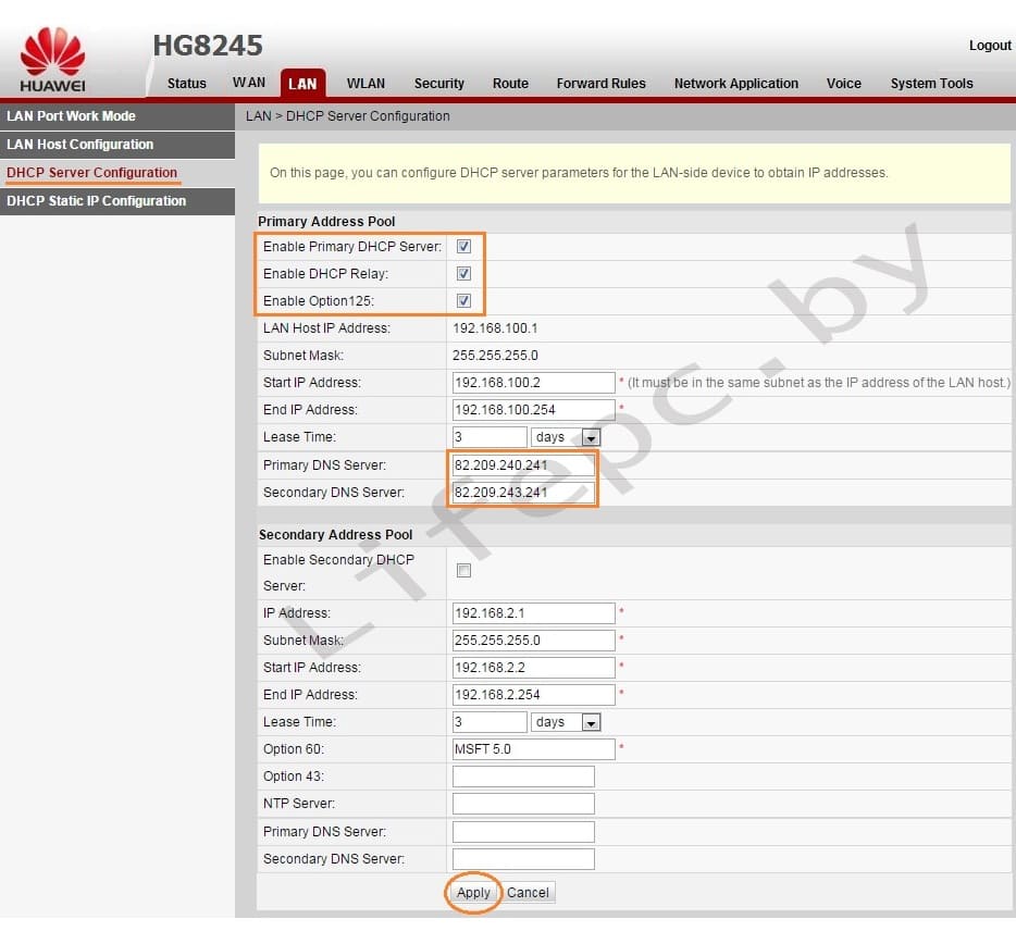
- Выбираем пункт LAN.
- В левом меню выбираем DHCP Server Configuration.
- Ставим галочку в строке Enable primary DHCP Server.
- Ставим галочку в строчке Enable DHCP Relay.
- Ставим галочку в строчке Enable Option 125.
- Вписываем Primary DNS и Secondary Server (как на изображении).
- Для принятия и сохранения настроек нажимаем кнопку «Apply»
Настройка Wi-Fi на модеме Huawei HG8245A | HG8245H-256M
Для настройки WIFI в верхнем меню выбираем вкладку WLAN.
- Устанавливаем галочку Enable WLAN.
- Нажимаем кнопку NEW.
- В поле SSID Name вписываем название беспроводной сети.
- Ставим галочку Enable SSID.
- Ставим галочку Broadcast SSID.
- Ставим галочку Enable WMM.
- Поле Number of Associated определяет одновременное количество подключенных устройств.
- В поле Authentication Mode выбираем WPA2 Pre-Shared Key или WPA\WPA2 Pre-Shared Key.
- В поле Encryption Mode ставим TKIP&AES.
- В поле WPA PreSharedKey вводим пароль для Wi-Fi.
- Сохраняем настройки нажимая кнопку «Apply».

Настроить модем Huawei HG8245A | HG8245H-256M не так уж и сложно если все делать аккуратно и не спеша согласно инструкции написанной выше. Надеемся, что данная статья Вам помогла и вы настроили свой модем Huawei HG8245A.
- Как усилить слабый Wi-Fi сигнал