Reverse engineering
Getting the physical address manually
So far we’ve figured that the virtual address is the same as linear address, so in the next part of the article we can use virtual addresses because they are the same as linear. Let’s take a look at the 0x0012ff60 virtual/linear address and try to figure out how to get physical address out of it. First, we must obtain the address of the page directory table, which contains the PDEs. To get the base address of the page directory table, we can simply read the contents of the CR3 register, which acts as the page directory base registers (PDBR) and points to the physical address of the first table (if PAE is enabled, we’re talking about the PDPT table, otherwise PDT page directory table). We can view the contents of the CR3 register by executing the «r cr3» command as can be seen in the picture below:

Become a certified reverse engineer!
Get live, hands-on malware analysis training from anywhere, and become a Certified Reverse Engineering Analyst.
![]()
The physical address of the page directory table is thus 0x095c0260. To verify that we’re looking at the right base physical address, we can run the !process command, which displays the DirBase value. This also contains the base address of the PDTD table. The result of running the !process command can be seen on the picture below:
![]()
Notice that the DirBase specifies the 0x095c0260 physical address? This confirms that we’re talking about the right address. The same information can also be obtained from the EPROCESS structure. To display the EPROCESS structure of a particular process, we can use the «dtnt!_EPROCESS addr» command as seen below. The 0x8200d5c0 is the address of the process structure in memory, which was obtained by the previous !process command.
![]()
We’re looking for the DirectoryTableBase element, which is further contained in the Pcb KPROCESS element. To dump that element, we can use the «dtn!_KPROCESS<addr>» command. This can be seen below, where the 0x018 is the entry we’re looking for and again the address 0x95c0260 is displayed.
![]()
If we try to dump memory from the 0x095c0260 address, we won’t receive anything useful (the data at those addresses is not defined). The result of running the «dd 095c0260» command can be seen on the picture below:
![]()
What’s happening? There should be a PDPT table with defined PDPTE entries or page directory table with defined PDE entries at that address!It’s true, the PDPTE or PDE entries should be present, and indeed they are. We’ve just made a mistake that often pops-up. The address in the CR3 register is the physical address, while the dd command dumps the values from virtual addresses, so what we’ve actually done is dump memory at virtual address 0x94401a0. To dump physical memory from that address, we need to prepend the character ‘!’ to the ddcommand . The actual command to dump from physical address thus becomes !dd and can be seen on the picture below:
![]()
Now we see some values defined, which is very cool and just what we wanted to get. Since in our case PAE is enabled, we’ve just dumped the four entries from the PDPT table: each of those entries is 64-bits long. The actual PDPTE entries are the following (taken from the first two lines from the above picture):
- 1ad40001
- 1aabf001
- 1aa3e001
- 1a8a1001
Let’s now take our linear addresses and split them into four parts corresponding to the format when PAE is enabled: the first part is an index into the PDPT table, the second part is an index into the page directory table, the third part is the index into the page table, and the fourth part is the last 12-bits of the actual physical address. Let’s use the .formats command to display our linear addresses in different representations:
- 0x0012ff60 : 00 | 000000000 | 100101111 | 111101100000
- 0x00345988 : 00 | 000000001 | 101000101 | 100110001000
I’ve separated the linear addresses into the four parts separated by character ‘|’. The first part is 0x00 in both cases, which means that the first entry from the PDPT table is used to resolve both of the linear addresses into physical addresses. The first entry in the PDPT table is: 0x1ad40001. The first 12 bits in the address must be discarded, because those bits are used for offset only, so the 001 bits become 000 and the base physical address of the second table is thus 0x1ad40000 (this is the base address into the PDT table). Now that we have the base address of the PDT table, we must again use the .formats command to display it in different representations (the binary form). The PDE entry must be split in a couple of elements, but for now we’re only interested in the base physical address of the page table, which is contained in the 12-31-bits (again the binary representation is splitted with the ‘|’ character). We also need to present the right PDE entries, based on the index into the PDT table. Since both linear addresses use the first PDPTE entry 0x1ad40000, a binary representation of that address is in order:
![]()
Since the lower 12-bits are discarded, the rest of the bits areas follows: 00011010 11010100 0000. We can transform the binary number back into the hexadecimal representation with the «? 0y00011010110101000000» command:
![]()
The base address of the PDT table is then 0x1ad40000. Then we need to get the address of the PDE, where we must add the index number 0x00000000 and 0x00000001 multiplied by 8 to the base address of the PDT table (for both linear addresses), which is in this case. Since the indexes from the linear address specify 0x0 and 0x1, we must read the first and the second index entry from the PDT table. This can be seen on the picture below:
![]()
We have just gotten two base addresses of the page table, so we must again apply the right indexes to read the appropriate PTE. The first index into the page table located at 0x1abf5067 is 100101111 and the second index into the page table located at 0x1aaea067 is 101000101 (check out the linear address binary representation if you don’t know what we’re talking about). Now we know the addresses of two base page tables: 0x1abf5000 and 0x1aaea000 and we also know the indexes (the lower bits needs to be zeroed out). It’s time to calculate the corresponding PTE entries:
![]()
We have obtained the physical base addresses to the pages in memory and we only need to apply the offset from the linear address to get to the actual physical value in memory. The two pages in memory have addresses 0x1aaf6000 and 0x1a851000 (again the lower 12-bits need to be zeroed out).
![]()
And finally we’ve gotten the physical addresses of the variable x and y. The physical address of the variable x is 0x1aaf6f60, while the physical address of the variable y is 0x1a851988. We can see that the values haven’t been initialized to 0xA and 0x14 yet. Now we need to step through the following instructions from the example:
[plain]
004113f5 c745f80a000000 movdwordptr [ebp-8],0Ah
004113ff c70014000000 movdwordptr [eax],14h
[/plain]
The first instruction saves the number 10 to the address of the variable x, while the second instruction saves the number 20 to the address of the variable y. We need to set breakpoints on them and run the program, but pause it right after the second instruction has been executed. Then we can observe values that have been written into the virtual and physical addresses. On the picture below, we can see that we first used the g command to run the program till the first breakpoint was hit and then stepped through the program until after the execution of the second instruction. This can be seen on the picture below:
![]()
Let’s now use the dd command to display the values from the virtual addresses:
![]()
The result is expected, the variable x located at address 0x0012ff60 contains the value 0xA, while the variable y located at address 0x00345988 contains the value 0x14. But what will happen if we dump the contents of the previously calculated physical addresses?In a best-case scenario the same numbers should be printed, which would mean that we didn’t make a mistake in the translation process. If the same numbers are not displayed, you’ve probably made a mistake when translating the virtual address to the corresponding physical address. On the picture below we’ve dumped the contents of the physical addresses and we can see that the values are the same, which proves that we’ve successfully calculated the physical addresses:
![]()
Getting the physical address automatically
Above, we’ve walked all the tables that are used to translate the virtual memory into physical memory manually. At the end we’ve been able to get the actual physical addresses to the corresponding virtual addresses, but we had to do a lot of work to translate one single address. Isn’t there a better way of doing this? Of course there is!Windbg provides two commands that can help us with that:the !pte and !vtop commands. To display the whole translation routine, we can execute the «!vtop 0 0x0012ff60» command, where the first argument 0 specifies that we would like to use the currently debugged process’s context. The first parameter to !vtop command is the page frame number, which is the same number as DirBase without the trailing three bytes. The second parameter specifies the virtual address to translate into physical address. Before being able to use the !vtop command, we must use the «!process 0 0» command to display the environmental variables – particularly DirBase– of the current process, and then use .process command to set the current index into the process’s context switch structure in memory. After that we can use the !vtop command successfully, as can be seen below:
![]()
![]()
Notice that !vtop command finds the base addresses of PDPE, PDE, PTE and also the resulting physical address. Now we can check whether the resulting physical addresses are the same as we identified in the previous section where we’ve manually inspected the translation process.
But there’s another command named !pte that can also be used to automatically convert between virtual and physical addresses. Before using it we must set the process context with «!process 0 0» as was already established. After that we can normally use the !pte command passing it the virtual address we would like to transform into a physical address:
![]()
The last row of the output from the !pte command displays the page frame number (note the pfn string) of the PTE. We know that this can be calculated from the DirBase variable that we get if we run «!process 0 0» by shifting the value to the right by 12 bits. To get the actual physical address, we need to shift the PFN to the left for 12-bits, and then add the last 12-bits of the virtual address to the newly gotten address and the result is the physical address. The last 3 bytes of the virtual address 0x0012ff60 are 0xf60, which we must add to the 1aaf6<<12 that constructs the physical address 0x1aaf6f60. The !pte command also displays the state of the flags in the PDE and PTE entries, which can be quite useful so we don’t have to inspect the memory manually. We can also apply the MMPTE_HARDWARE structure to the PDE entry and display it on the screen, which is visible on the picture below:
![]()
The 0xC0600000 is the PDE entry, which was used when translating the 0x0012ff60 virtual address.
Conclusion
In this series of articles, we’ve been able to manually translate the virtual address to a linear address and further into the physical address by navigating the directory and page tables. We’ve seen that the translation process is too complicated.All we need to know are the details about a few pages that are stored in memory, take their entries, inspect them, and examine them further. If you’re serious about kernel debugging, you should really understand how the virtual addresses get translated into physical addresses. Once you truly understand it, you can use the !pte or !vtop commands in Windbg that do the translation automatically.
Sources
[1] x86 memory management and linux kernel, accessible at http://manavar.blogspot.com/2011/05/x86-memory-management-and-linux-kernel.html.
[2] http://www.intel.com/content/www/us/en/processors/architectures-software-developer-manuals.html.
[3] W4118: segmentation and paging, accessible at http://www.cs.columbia.edu/~junfeng/os/Flectures/l05-mem.pdf.
[4] Common WinDbg Commands, accessible at http://www.windbg.info/doc/1-common-cmds.html.
[5] Understanding !PTE , Part 1: Let’s get physical, accessible at http://blogs.msdn.com/b/ntdebugging/archive/2010/02/05/understanding-pte-part-1-let-s-get-physical.aspx.
[6] Understanding !PTE, Part2: Flags and Large Pages, accessible at http://blogs.msdn.com/b/ntdebugging/archive/2010/04/14/understanding-pte-part2-flags-and-large-pages.aspx.

[7] Part 3: Understanding !PTE — Non-PAE and X64, accessible at http://blogs.msdn.com/b/ntdebugging/archive/2010/06/22/part-3-understanding-pte-non-pae-and-x64.aspx.
Search code, repositories, users, issues, pull requests…
Provide feedback
Saved searches
Use saved searches to filter your results more quickly
Sign up
In my C++ program (on Windows), I’m allocating a block of memory and can make sure it stays locked (unswapped and contiguous) in physical memory (i.e. using VirtualAllocEx(), MapUserPhysicalPages() etc).
No, you can’t really ensure that it stays locked. What if your process crashes, or exits early? What if the user kills it? That memory will be reused for something else, and if your device is still doing DMA, that will eventually result in data loss/corruption or a bugcheck (BSOD).
Also, MapUserPhysicalPages is part of Windows AWE (Address Windowing Extensions), which is for handling more than 4 GB of RAM on 32-bit versions of Windows Server. I don’t think it was intended to be used to hack up user-mode DMA.
1. Is there any way I can translate the virtual address to the physical one within my program, in USER mode?
There are drivers that let you do this, but you cannot program DMA from user mode on Windows and still have a stable and secure system. Letting a process that runs as a limited user account read/write physical memory allows that process to own the system. If this is for a one-off system or a prototype, this is probably acceptable, but if you expect other people (particularly paying customers) to use your software and your device, you should write a driver.
2. If not, I can find out this virtual to physical mapping only in KERNEL mode. I guess it means I have to write a driver to do it…?
That is the recommended way to approach this problem.
Do you know of any readily available driver/DLL/API which I can use, that my application (program) will interface with to do the translation?
You can use an MDL (Memory Descriptor List) to lock down arbitrary memory, including memory buffers owned by a user-mode process, and translate its virtual addresses into physical addresses. You can also have Windows temporarily create an MDL for the buffer passed into a call to DeviceIoControl by using METHOD_IN_DIRECT or METHOD_OUT_DIRECT.
Note that contiguous pages in the virtual address space are almost never contiguous in the physical address space. Hopefully your device is designed to handle that.
3. In case I’ll have to write the driver myself, how do I do this translation? which functions do I use? Is it mmGetPhysicalAddress()? How do I use it?
There’s a lot more to writing a driver than just calling a few APIs. If you’re going to write a driver, I would recommend reading as much relevant material as you can from MSDN and OSR. Also, look at the examples in the Windows Driver Kit.
4. Also, if I understand correctly, mmGetPhysicalAddress() returns the physical address of a virtual base address that is in the context of the calling process. But if the calling process is the driver, and I’m using my application to call the driver for that function, I’m changing contexts and I am no longer in the context of the app when the mmGetPhysicalAddress routine is called… so how do I translate the virtual address in the application (user-mode) memory space, not the driver?
Drivers are not processes. A driver can run in the context of any process, as well as various elevated contexts (interrupt handlers and DPCs).
Windows memory management knowledge summary
This article is mainly to understand the mapping of virtual addresses to physical addresses under the 32-bit Windows operating system.
First of allWindows memory management mechanismGive a brief introduction.
Windows allocates 4GB of virtual address space for each process, making each process think that it has 4GB of memory space.
Then the Windows system divides the 4GB space into two parts, the process and the system, and each process can get 2GB of virtual memory, according to the available capacity. Assigned to all processesTotal virtual memoryCannot exceed the sum of the page file and most of the physical memory (the operating system itself also occupies a small part of the physical memory).
The 4G memory space of each process is just a virtual memory space. Every time an address in the memory space is accessed, the address needs to be translated into an actual physical memory address
All processes share the same physical memory, and each process only maps and stores the virtual memory space it currently needs to the physical memory.
Below we will discuss how to map virtual addresses to physical addresses under the Windows operating system.
When a process is created, a virtual memory-to-physical memory mapping table will be established ——— page table. According to the page table, virtual memory and physical memory can be associated
Memory paging
The memory mapping needs to pass through the page table. First, we think about why paging is required?
When the program is running, the process needs to read the code of this program from memory. The location of the code must be in physical memory before it can be run. Because there are so many programs running in the operating system, it is impossible to completely put all the physical pages in the memory, so the concept of virtual memory is introduced.
Put uncommon program fragments into virtual memory, and load them into main memory (physical memory) when they are needed. This is what the memory management needs to do. Memory management has another thing to do: calculate the physical location of program fragments in main memory for CPU scheduling.
This scheduling uses memory paging and is mapped through the page table.
So how is it mapped?
Win32 implements address mapping through a two-level table structure
Page directory, Is actually a memory page, Win32 memory page has a size of 4KB, this memory page is divided into 1024 items in 4 bytes, each item is called «page directory entry» (PDE);
Page tableThere are 1024 page tables in this layer. The structure of the page table is similar to the page directory. Each page table is also a memory page. This memory page is divided into 1024 items with a size of 4KB. Each item of the page table is called It is a page table entry (PTE), it is easy to know that there are 1024×1024 page table entries. Each page table entry corresponds to a certain «memory page» in a physical memory, that is, there are a total of 1024×1024 physical memory pages, and each physical memory page is 4KB, so that a 4G virtual physical memory can be indexed.
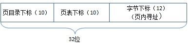
The actual process isCR3->Page Directory Item->Page Table Item->Memory Page->Offset=Physical Address
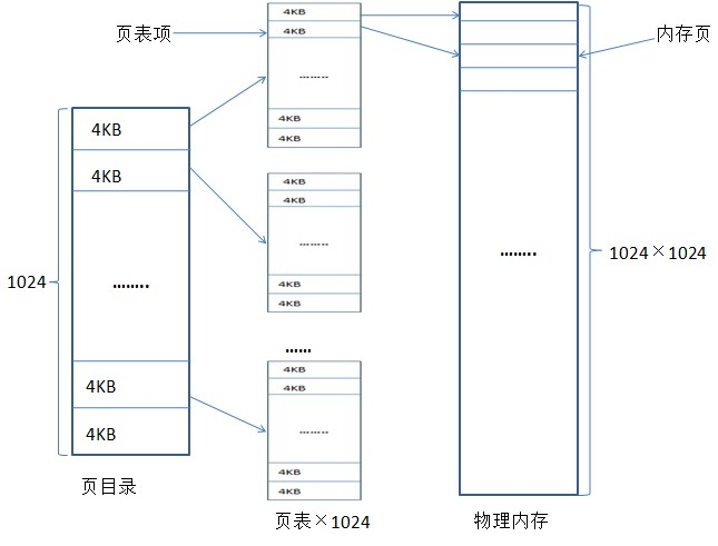
Of course, the premise of the above assumption is that the data is already in physical memory.
When the access data is already in the physical memory, follow the above steps to perform address mapping, and then access the data.
If the current data is not on the physical page, a page fault interrupt will be thrown, and then judge whether the data is in the page swap file?
If it is not, the access is violated and the program will exit. If it is, the page table item will find out which paging file the data page is in, and then load the data page into physical memory. Then continue address mapping.
realizes that each process has a private 4G virtual address space, which means that each process has its own page directory and page table structure. For different processes, even if they are the same The physical addresses mapped to pointers (virtual addresses) by different processes are also different, which also means that it is meaningless to pass pointers between processes.
reference:
«Windows Core Programming»
Now that you’ve seen how Windows structures the virtual address space, let’s look at how it maps these address spaces to real physical pages. User applications and system code reference virtual addresses. This section starts with a detailed description of 32-bit x86 address translation, followed by a brief description of the differences on the 64-bit IA-64 and x64 platform. In the next section, we’ll describe what happens when such a translation doesn’t resolve to a physical memory address (paging) and explain how Windows manages physical memory via working sets and the page frame database.
x86 Virtual Address Translation
Using data structures the memory manager creates and maintains called page tables, the CPU translates virtual addresses into physical addresses. Each virtual address is associated with a system-space structure called a page table entry (PTE), which contains the physical address to which the virtual one is mapped. For example, Figure 7-15 shows how three consecutive virtual pages are mapped to three physically discontiguous pages on an x86.
Figure 7-15. Mapping virtual addresses to physical memory (x86)
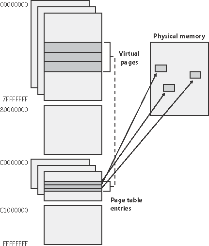
The dashed line connecting the virtual pages to the PTEs in Figure 7-15 represents the indirect relationship between virtual pages and physical memory.
Note
|
Kernel-mode code (such as device drivers) can reference physical memory addresses by mapping them to virtual addresses. For more information, see the memory descriptor list (MDL) support routines described in the DDK documentation. |
By default, Windows on an x86 system uses a two-level page table structure to translate virtual to physical addresses. (x86 systems running the PAE kernel use a three-level page table this section assumes non-PAE systems.) A 32-bit virtual address is interpreted as three separate components the page directory index, the page table index, and the byte index that are used as indexes into the structures that describe page mappings, as illustrated in Figure 7-16. The page size and the PTE width dictate the width of the page directory and page table index fields. For example, on x86 systems, the byte index is 12 bits because pages are 4096 bytes (212 = 4096).
Figure 7-16. Components of a 32-bit virtual address on x86 systems
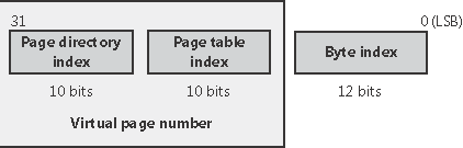
The page directory index is used to locate the page table in which the virtual address’s PTE is located. The page table index is used to locate the PTE, which, as mentioned earlier, contains the physical address to which a virtual page maps. The byte index finds the proper address within that physical page. Figure 7-17 shows the relationship of these three values and how they are used to map a virtual address into a physical address.
Figure 7-17. Translating a valid virtual address (x86-specific)
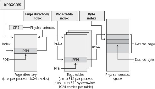
The following basic steps are involved in translating a virtual address:
-
The memory management hardware locates the page directory for the current process. On each process context switch, the hardware is told the address of a new process page directory, typically by the operating system setting a special CPU register.
-
The page directory index is used as an index into the page directory to locate the page directory entry (PDE) that describes the location of the page table needed to map the virtual address. The PDE contains the page frame number (PFN) of the page table (if it is resident page tables can be paged out).
-
The page table index is used as an index into the page table to locate the PTE that describes the physical location of the virtual page in question.
-
The PTE is used to locate the page. If the page is valid, it contains the PFN of the page in physical memory that contains the virtual page. If the PTE indicates that the page isn’t valid, the memory management fault handler locates the page and tries to make it valid. (See the section on page fault handling.) If the page can’t be made valid (for example, because of a protection fault), the fault handler generates an access violation or a bug check.
-
When the PTE is pointed to a valid page, the byte index is used to locate the address of the desired data within the physical page.
Now that you have the overall picture, let’s look at the detailed structure of page directories, page tables, and PTEs.
Page Directories
Each process has a single page directory, a page the memory manager creates to map the location of all page tables for that process. The physical address of the process page directory is stored in the kernel process (KPROCESS) block, but it is also mapped virtually at address 0xC0300000 on x86 systems (0xC0600000 on systems running the PAE kernel image). All code running in kernel mode references virtual addresses, not physical ones. (For more detailed information about KPROCESS and other process data structures, refer to Chapter 6.)
The CPU knows the location of the page directory page because a special register (CR3 on x86 systems) inside the CPU that is loaded by the operating system contains the physical address of the page directory. Each time a context switch occurs to a thread that is in a different process than that of the currently executing thread, this register is loaded from the KPROCESS block of the target process being switched to by the context-switch routine in the kernel. Context switches between threads in the same process don’t result in reloading the physical address of the page directory because all threads within the same process share the same process address space.
The page directory is composed of page directory entries (PDEs), each of which is 4 bytes long (8 bytes on systems running the PAE kernel image) and describes the state and location of all the possible page tables for that process. (As described later in the chapter, page tables are created on demand, so the page directory for most processes points only to a small set of page tables.) The format of a PDE isn’t repeated here because it’s mostly the same as a hardware PTE.
On x86 systems running in non-PAE mode, 1024 page tables are required to describe the full 4-GB virtual address space. The process page directory that maps these page tables contains 1024 PDEs. Therefore, the page directory index needs to be 10 bits wide (210 = 1024). On x86 systems running in PAE mode, there are 512 entries in a page table (because the page directory index is 9 bits wide). Because there are 4 page directories, the result is a maximum of 2048 page tables.
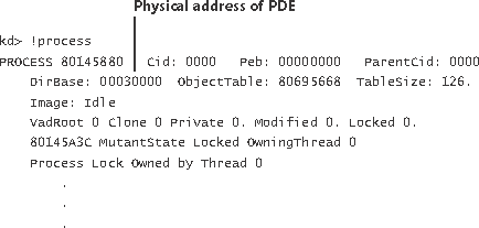
EXPERIMENT: Examining the Page Directory and PDEsYou can see the physical address of the currently running process’s page directory by examining the DirBase field in the !process kernel debugger output:
You can see the page directory’s virtual address by examining the kernel debugger output for the PTE of a particular virtual address, as shown here:
The PTE part of the kernel debugger output is defined in the section «Page Table Entries.» |
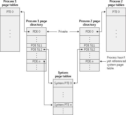
Because Windows provides a private address space for each process, each process has its own set of process page tables to map that process’s private address space. However, the page tables that describe system space are shared among all processes (and session space is shared among processes in a session). To avoid having multiple page tables describing the same virtual memory, when a process is created, the page directory entries that describe system space are initialized to point to the existing system page tables. If the process is part of a session, session space page tables are also shared by pointing the session space page directory entries to the existing session page tables.
But as shown in Figure 7-18, not all processes have the same view of system space. For example, if paged pool expansion requires the allocation of a new system page table, the memory manager doesn’t go back and update all the process page directories to point to the new system page table. Instead, it updates the process page directories when the processes reference the new virtual address.
Figure 7-18. System and process-private page tables
Thus, a process can take a page fault when referencing paged pool that is in fact physically resident because its process page directory doesn’t yet point to the new system page table that describes the new area of pool. Page faults don’t occur when accessing nonpaged pool, even though it too can be expanded, because Windows builds enough system page tables to describe the maximum size during system initialization.
Page Tables and Page Table Entries
The process page directory entries point to individual page tables. Page tables are composed of an array of PTEs. The virtual address’s page table index field (as shown in Figure 7-17) indicates which PTE within the page table maps the data page in question. On x86 systems, the page table index is 10 bits wide (9 on PAE), allowing you to reference up to 1024 4-byte PTEs (512 8-byte PTEs on PAE systems). However, because 32-bit Windows provides a 4-GB private virtual address space, more than one page table is needed to map the entire address space. To calculate the number of page tables required to map the entire 4-GB process virtual address space, divide 4 GB by the virtual memory mapped by a single page table. Recall that each page table on an x86 system maps 4 MB (2 MB on PAE) of data pages. Thus, 1024 page tables (4 GB/4 MB) or 2048 page tables (4 GB/2 MB) for PAE are required to map the full 4-GB address space.
You can use the !pte command in the kernel debugger to examine PTEs. (See the experiment «Translating Addresses.») We’ll discuss valid PTEs here and invalid PTEs in a later section. Valid PTEs have two main fields: the page frame number (PFN) of the physical page containing the data or of the physical address of a page in memory, and some flags that describe the state and protection of the page, as shown in Figure 7-19.
Figure 7-19. Valid x86 hardware PTEs

As you’ll see later, the bits labeled Reserved in Figure 7-19 are used only when the PTE isn’t valid. (The bits are interpreted by software.) Table 7-11 briefly describes the hardware-defined bits in a valid PTE.
|
Name of Bit |
Meaning |
|---|---|
|
Accessed |
Page has been read. |
|
Cache disabled |
Disables caching for that page. |
|
Dirty |
Page has been written to. |
|
Global |
Translation applies to all processes. (For example, a translation buffer flush won’t affect this PTE.) |
|
Large page |
Indicates that the PDE maps a 4-MB page (or 2 MB on PAE systems). See the section «Large and Small Pages» earlier in the chapter. |
|
Owner |
Indicates whether user-mode code can access the page or whether the page is limited to kernel-mode access. |
|
Valid |
Indicates whether the translation maps to a page in physical memory. |
|
Write through |
Disables caching of writes to this page so that changes are immediately flushed to disk. |
|
Write |
On uniprocessor systems, indicates whether the page is read/write or readonly; on multiprocessor systems, indicates whether the page is writable. (The Write bit is stored in a reserved bit in the PTE.) |
On x86 systems, a hardware PTE contains a Dirty bit and an Accessed bit. The Accessed bit is clear if a physical page represented by the PTE hasn’t been read or written; the processor sets this bit when the page is first read or written. The processor sets the Dirty bit only when a page is first written. In addition to those two bits, the x86 architecture has a Write bit that provides page protection. When this bit is clear, the page is read-only; when it is set, the page is read/ write. If a thread attempts to write to a page with the Write bit clear, a memory management exception occurs and the memory manager’s access fault handler (described in the next section) must determine whether the thread can write to the page (for example, if the page was really marked copy-on-write) or whether an access violation should be generated.
Hardware PTEs on multiprocessor x86 systems have an additional Write bit implemented in software that is intended to avoid stalls when flushing the PTE cache (called the translation look-aside buffer, described in the next section) across processors. This bit indicates that a page has been modified by another processor.
Byte Within Page
Once the memory manager has found the physical page in question, it must find the requested data within that page. This is where the byte index field comes in. The byte index field tells the CPU which byte of data in the page you want to reference. On x86 systems, the byte index is 12 bits wide, allowing you to reference up to 4096 bytes of data (the size of a page). So, adding the byte offset to the physical page number retrieved from the PTE completes the translation of a virtual address to a physical address.
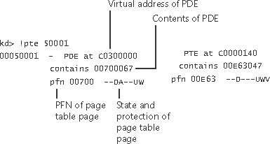
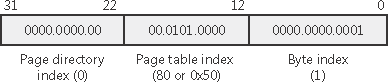
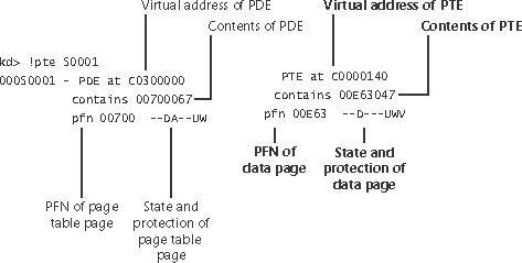
EXPERIMENT: Translating AddressesTo clarify how address translation works, let’s go through a real example of translating a virtual address on an x86 non-PAE system, using the available tools in the kernel debugger to examine page directories, page tables, and PTEs. In this example, we’ll use a process that has virtual address 0x50001 currently mapped to a valid physical address. In later examples, you’ll see how to follow address translation for invalid addresses with the kernel debugger. First let’s convert 0x50001 to binary and break it into the three fields that are used to translate an address. In binary, 0x50001 is 101.0000.0000.0000.0001. Breaking it into the component fields yields the following:
To start the translation process, the CPU needs the physical address of the process page directory, stored in the CR3 register while a thread in that process is running. You can display this address either by examining the CR3 register itself or by dumping the KPROCESS block for the process in question using the !process command, as shown here:
In this case, the page directory is stored at physical address 0x12F0000. As shown in the preceding illustration, the page directory index field in this example is 0. Therefore, the PDE is at physical address 0x12F0000. The kernel debugger !pte command displays the PDE and PTE that describe a virtual address, as shown here:
In the first column the kernel debugger displays the PDE, and in the second column it displays the PTE. Notice that the PDE address is shown as a virtual address, not a physical address as noted earlier, the process page directory starts at virtual address 0xC0300000 on x86 systems. Because we’re looking at the first PDE in the page directory, the PDE address is the same as the page directory address. The PTE is at virtual address 0xC0000140. You can compute this address by multiplying the page table index (0x50 in this example) by the size of a PTE: 0x50 multiplied by 4 equals 0x140. Because the memory manager maps page tables starting at 0xC0000000, adding 140 yields the virtual address shown in the kernel debugger output: 0xC0000140. The page table page is at PFN 0x700, and the data page is at PFN 0xe63. The PTE flags are displayed to the right of the PFN number. For example, the PTE that describes the page being referenced has flags of D UWV. D here stands for dirty (the page has been modified), U for user-mode page (as opposed to a kernel-mode page), W for writable page (rather than read-only), and V for valid. (The PTE represents a valid page in physical memory.) |

Translation Look-Aside Buffer
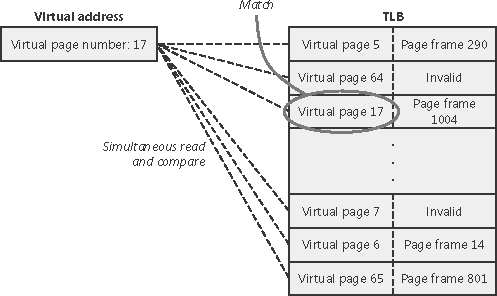
As we’ve learned so far, each address translation requires two lookups: one to find the right page table in the page directory and one to find the right entry in the page table. Because doing two additional memory lookups for every reference to a virtual address would result in unacceptable system performance, most CPUs cache address translations so that repeated accesses to the same addresses don’t have to be retranslated. The processor provides such a cache in the form of an array of associative memory called the translation look-aside buffer, or TLB. Associative memory, such as the TLB, is a vector whose cells can be read simultaneously and compared to a target value. In the case of the TLB, the vector contains the virtual-to-physical page mappings of the most recently used pages, as shown in Figure 7-20, and the type of page protection applied to each page. Each entry in the TLB is like a cache entry, whose tag holds portions of the virtual address and whose data portion holds a physical page number, protection field, valid bit, and usually a dirty bit indicating the condition of the page to which the cached PTE corresponds. If a PTE’s global bit is set (used for system space pages that are globally visible to all processes), the TLB entry isn’t invalidated on process context switches.
Figure 7-20. Accessing the translation look-aside buffer
Virtual addresses that are used frequently are likely to have entries in the TLB, which provides extremely fast virtual-to-physical address translation and, therefore, fast memory access. If a virtual address isn’t in the TLB, it might still be in memory, but multiple memory accesses are needed to find it, which makes the access time slightly slower. If a virtual page has been paged out of memory or if the memory manager changes the PTE, the memory manager explicitly invalidates the TLB entry. If a process accesses it again, a page fault occurs and the memory manager brings the page back into memory and re-creates an entry for it in the TLB.
To maximize the amount of common code, the memory manager treats all PTEs the same whenever possible, whether they are maintained by hardware or by software. For example, the memory manager calls a kernel routine when a PTE changes from invalid to valid. The job of this routine is to load this new PTE into the TLB in whatever hardware-specific manner the architecture requires. On x86 systems, the code is a NOP because the processor loads the TLB without any intervention from the software.
Physical Address Extension (PAE)
The Intel x86 Pentium Pro processor introduced a memory-mapping mode called Physical Address Extension (PAE). With the proper chipset, the PAE mode allows access to up to 64 GB of physical memory on current Intel x86 processors and 1024 GB of physical memory on x64 processors (though Windows currently limits this to 128 GB due to the size of the PFN database required to map so much memory). When the processor executes in PAE mode, the memory management unit (MMU) divides virtual addresses into four fields, as shown in Figure 7-21.
Figure 7-21. Page mappings with PAE
The MMU still implements page directories and page tables, but a third level, the page directory pointer table, exists above them. PAE mode can address more memory than the standard translation mode not because of the extra level of translation but because PDEs and PTEs are 64 bits wide rather than 32 bits. The system represents physical addresses internally with 25 bits, which gives the ability to support a maximum of 225+12 bytes, or 128 GB, of memory. One way in which 32-bit applications can take advantage of such large memory configurations is described in the earlier section «Address Windowing Extensions.» However, even if applications are not using such functions, the memory manager will use all available physical memory for file cache data through the use of the system cache, standby, and modified lists (described in the section «Page Frame Number Database»).
As explained in Chapter 2, there is a special version of the 32-bit Windows kernel with support for PAE called Ntkrnlpa.exe. To select this PAE-enabled kernel, you must boot with the /PAE switch in Boot.ini. Note that this special version of the kernel image is installed on all 32-bit Windows systems, even Windows 2000 Professional or Windows XP systems with small memory. The reason for this is to facilitate device driver testing. Because the PAE kernel presents 64-bit addresses to device drivers and other system code, booting /PAE even on a small memory system allows device driver developers to test parts of their drivers with large addresses. The other relevant Boot.ini switch is /NOLOWMEM, which discards memory below 4 GB (assuming you have at least 5 GB of physical memory) and relocates device drivers above this range. This guarantees that drivers will be presented with physical addresses greater than 32 bits, which makes any possible driver sign extension bugs easier to find.
IA-64 Virtual Address Translation
The virtual address space for IA-64 is divided into eight regions by the hardware. Each region can have its own set of page tables. Windows uses five of the regions, three of which have page tables. Table 7-12 lists the regions and how they are used.
|
Region |
Use |
|---|---|
|
0 |
User code and data |
|
1 |
Session space code and data |
|
2 |
Unused |
|
3 |
Unused |
|
4 |
Kseg3, which is a cached 1-to-1 mapping of physical memory. No page tables are needed for this region because the necessary TLB inserts are done directly by the memory manager. |
|
5 |
Kseg4, which is a noncached 1-to-1 mapping for physical memory. This is used only in a few places for accessing I/O locations such as the I/O port range. There are no page tables needed for this region. |
|
6 |
Unused |
|
7 |
Kernel code and data |
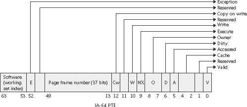
Address translation by 64-bit Windows on the IA-64 platform uses a three-level page table scheme. Each process has a page directory pointer structure that contains 1024 pointers to page directories. Each page directory contains 1024 pointers to page tables, which in turn point to physical pages. Figure 7-22 shows the format of an IA-64 hardware PTE.
Figure 7-22. IA-64 page table entry
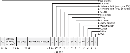
x64 Virtual Address Translation
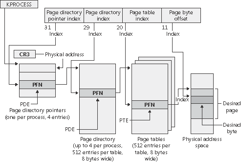
64-bit Windows on the x64 architecture uses a four-level page table scheme. Each process has a top level extended page directory (called the page map level 4) that contains 512 pointers to a third-level structure called a page parent directory. Each page parent directory contains 512 pointers to second-level page directories, each of which contain 512 pointers to the individual page tables. Finally, the page tables (each of which contain 512 page table entries) point to pages in memory. Current implementations of the x64 architecture limit virtual addresses to 48 bits. The components that make up this 48-bit virtual address are shown in Figure 7-23. The connections between these structures are shown in Figure 7-24. Finally, the format of an x64 hardware page table entry is shown in Figure 7-25.
Figure 7-23. x64 virtual address
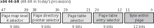
Figure 7-24. x64 address translation structures
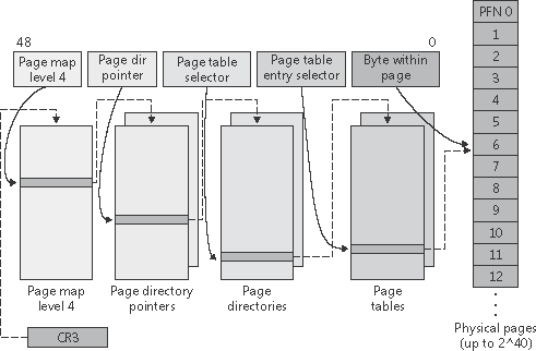
Figure 7-25. x64 hardware page table entry