I think that I shall never see
A graph more lovely than a tree.
A tree whose crucial propertyеу
Is loop-free connectivity.
A tree that must be sure to span
So packets can reach every LAN.
First, the root must be selected.
By ID, it is elected.
Least-cost paths from root are traced.
In the tree, these paths are placed.
A mesh is made by folks like me,
Then bridges find a spanning tree.
— Radia Joy Perlman
Все выпуски
6. Сети для самых маленьких. Часть шестая. Динамическая маршрутизация
5. Сети для самых маленьких: Часть пятая. NAT и ACL
4. Сети для самых маленьких: Часть четвёртая. STP
3. Сети для самых маленьких: Часть третья. Статическая маршрутизация
2. Сети для самых маленьких. Часть вторая. Коммутация
1. Сети для самых маленьких. Часть первая. Подключение к оборудованию cisco
0. Сети для самых маленьких. Часть нулевая. Планирование
В прошлом выпуске мы остановились на статической маршрутизации. Теперь надо сделать шаг в сторону и обсудить вопрос стабильности нашей сети.
Однажды, когда вы — единственный сетевой админ фирмы “Лифт ми Ап” — отпросились на полдня раньше, вдруг упала связь с серверами, и директора не получили несколько важных писем. После короткой, но ощутимой взбучки вы идёте разбираться, в чём дело, а оказалось, по чьей-то неосторожности выпал из разъёма единственный кабель, ведущий к коммутатору в серверной. Небольшая проблема, которую вы могли исправить за две минуты, и даже вообще избежать, существенно сказалась на вашем доходе в этом месяце и возможностях роста.
Итак, сегодня обсуждаем:
- проблему широковещательного шторма
- работу и настройку протокола STP и его модификаций (RSTP, MSTP, PVST, PVST+)
- технологию агрегации интерфейсов и перераспределения нагрузки между ними
- некоторые вопросы стабильности и безопасности
- как изменить схему существующей сети, чтобы всем было хорошо
Оборудование, работающее на втором уровне модели OSI (коммутатор), должно выполнять 3 функции: запоминание адресов, перенаправление (коммутация) пакетов, защита от петель в сети. Разберем по пунктам каждую функцию.
Запоминание адресов и перенаправление пакетов: Как мы уже говорили ранее, у каждого свича есть таблица сопоставления MAC-адресов и портов (aka CAM-table — Content Addressable Memory Table). Когда устройство, подключенное к свичу, посылает кадр в сеть, свич смотрит MAC-адрес отправителя и порт, откуда получен кадр, и добавляет эту информацию в свою таблицу. Далее он должен передать кадр получателю, адрес которого указан в кадре. По идее, информацию о порте, куда нужно отправить кадр, он берёт из этой же CAM-таблицы. Но, предположим, что свич только что включили (таблица пуста), и он понятия не имеет, в какой из его портов подключен получатель. В этом случае он отправляет полученный кадр во все свои порты, кроме того, откуда он был принят. Все конечные устройства, получив этот кадр, смотрят MAC-адрес получателя, и, если он адресован не им, отбрасывают его. Устройство-получатель отвечает отправителю, а в поле отправителя ставит свой адрес, и вот свич уже знает, что такой-то адрес находится на таком-то порту (вносит запись в таблицу), и в следующий раз уже будет переправлять кадры, адресованные этому устройству, только в этот порт. Чтобы посмотреть содержимое CAM-таблицы, используется команда show mac address-table. Однажды попав в таблицу, информация не остаётся там пожизненно, содержимое постоянно обновляется и если к определенному mac-адресу не обращались 300 секунд (по умолчанию), запись о нем удаляется.
Тут всё должно быть понятно. Но зачем защита от петель? И что это вообще такое?
Широковещательный шторм
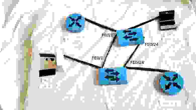
Часто, для обеспечения стабильности работы сети в случае проблем со связью между свичами (выход порта из строя, обрыв провода), используют избыточные линки (redundant links) — дополнительные соединения. Идея простая — если между свичами по какой-то причине не работает один линк, используем запасной. Вроде все правильно, но представим себе такую ситуацию: два свича соединены двумя проводами (пусть будет, что у них соединены fa0/1 и fa0/24).
Одной из их подопечных — рабочих станций (например, ПК1) вдруг приспичило послать широковещательный кадр (например, ARP-запрос). Раз широковещательный, шлем во все порты, кроме того, с которого получили.

Второй свич получает кадр в два порта, видит, что он широковещательный, и тоже шлет во все порты, но уже, получается, и обратно в те, с которых получил (кадр из fa0/24 шлет в fa0/1, и наоборот).
Первый свич поступает точно также, и в итоге мы получаем широковещательный шторм (broadcast storm), который намертво блокирует работу сети, ведь свичи теперь только и занимаются тем, что шлют друг другу один и тот же кадр.

Как можно избежать этого? Ведь мы, с одной стороны, не хотим штормов в сети, а с другой, хотим повысить ее отказоустойчивость с помощью избыточных соединений? Тут на помощь нам приходит STP (Spanning Tree Protocol)
STP
Основная задача STP — предотвратить появление петель на втором уровне. Как это сделать? Да просто отрубить все избыточные линки, пока они нам не понадобятся. Тут уже сразу возникает много вопросов: какой линк из двух (или трех-четырех) отрубить? Как определить, что основной линк упал, и пора включать запасной? Как понять, что в сети образовалась петля? Чтобы ответить на эти вопросы, нужно разобраться, как работает STP.
STP использует алгоритм STA (Spanning Tree Algorithm), результатом работы которого является граф в виде дерева (связный и без простых циклов)
Для обмена информацией между собой свичи используют специальные пакеты, так называемые BPDU (Bridge Protocol Data Units). BPDU бывают двух видов: конфигурационные (Configuration BPDU) и панические “ААА, топология поменялась!” TCN (Topology Change Notification BPDU). Первые регулярно рассылаются корневым свичом (и ретранслируются остальными) и используются для построения топологии, вторые, как понятно из названия, отсылаются в случае изменения топологии сети (проще говоря, подключении\отключении свича). Конфигурационные BPDU содержат несколько полей, остановимся на самых важных:
- идентификатор отправителя (Bridge ID)
- идентификатор корневого свича (Root Bridge ID)
- идентификатор порта, из которого отправлен данный пакет (Port ID)
- стоимость маршрута до корневого свича (Root Path Cost)
Что все это такое и зачем оно нужно, объясню чуть ниже. Так как устройства не знают и не хотят знать своих соседей, никаких отношений (смежности/соседства) они друг с другом не устанавливают. Они шлют BPDU из всех работающих портов на мультикастовый ethernet-адрес 01-80-c2-00-00-00 (по умолчанию каждые 2 секунды), который прослушивают все свичи с включенным STP.
Итак, как же формируется топология без петель?
Сначала выбирается так называемый корневой мост/свич (root bridge). Это устройство, которое STP считает точкой отсчета, центром сети; все дерево STP сходится к нему. Выбор базируется на таком понятии, как идентификатор свича (Bridge ID). Bridge ID это число длиной 8 байт, которое состоит из Bridge Priority (приоритет, от 0 до 65535, по умолчанию 32768+номер vlan или инстанс MSTP, в зависимости от реализации протокола), и MAC-адреса устройства. В начале выборов каждый коммутатор считает себя корневым, о чем и заявляет всем остальным с помощью BPDU, в котором представляет свой идентификатор как ID корневого свича. При этом, если он получает BPDU с меньшим Bridge ID, он перестает хвастаться своим и покорно начинает анонсировать полученный Bridge ID в качестве корневого. В итоге, корневым оказывается тот свич, чей Bridge ID меньше всех.
Такой подход таит в себе довольно серьезную проблему. Дело в том, что, при равных значениях Priority (а они равные, если не менять ничего) корневым выбирается самый старый свич, так как мак адреса прописываются на производстве последовательно, соответственно, чем мак меньше, тем устройство старше (естественно, если у нас все оборудование одного вендора). Понятное дело, это ведет к падению производительности сети, так как старое устройство, как правило, имеет худшие характеристики. Подобное поведение протокола следует пресекать, выставляя значение приоритета на желаемом корневом свиче вручную, об этом в практической части.
Роли портов
После того, как коммутаторы померились айдями и выбрали root bridge, каждый из остальных свичей должен найти один, и только один порт, который будет вести к корневому свичу. Такой порт называется корневым портом (Root port). Чтобы понять, какой порт лучше использовать, каждый некорневой свич определяет стоимость маршрута от каждого своего порта до корневого свича. Эта стоимость определяется суммой стоимостей всех линков, которые нужно пройти кадру, чтобы дойти до корневого свича. В свою очередь, стоимость линка определяется просто- по его скорости (чем выше скорость, тем меньше стоимость). Процесс определения стоимости маршрута связан с полем BPDU “Root Path Cost” и происходит так:
- Корневой свич посылает BPDU с полем Root Path Cost, равным нулю
- Ближайший свич смотрит на скорость своего порта, куда BPDU пришел, и добавляет стоимость согласно таблице
Скорость порта Стоимость STP (802.1d) 10 Mbps 100 100 Mbps 19 1 Gbps 4 10 Gbps 2 - Далее этот второй свич посылает этот BPDU нижестоящим коммутаторам, но уже с новым значением Root Path Cost, и далее по цепочке вниз
Если имеют место одинаковые стоимости (как в нашем примере с двумя свичами и двумя проводами между ними — у каждого пути будет стоимость 19) — корневым выбирается меньший порт.
Далее выбираются назначенные (Designated) порты. Из каждого конкретного сегмента сети должен существовать только один путь по направлению к корневому свичу, иначе это петля. В данном случае имеем в виду физический сегмент, в современных сетях без хабов это, грубо говоря, просто провод. Назначенным портом выбирается тот, который имеет лучшую стоимость в данном сегменте. У корневого свича все порты — назначенные.
И вот уже после того, как выбраны корневые и назначенные порты, оставшиеся блокируются, таким образом разрывая петлю.

*На картинке маршрутизаторы выступают в качестве коммутаторов. В реальной жизни это можно сделать с помощью дополнительной свитчёвой платы.
Состояния портов
Чуть раньше мы упомянули состояние блокировки порта, теперь поговорим о том, что это значит, и о других возможных состояниях порта в STP. Итак, в обычном (802.1D) STP существует 5 различных состояний:
- блокировка (blocking): блокированный порт не шлет ничего. Это состояние предназначено, как говорилось выше, для предотвращения петель в сети. Блокированный порт, тем не менее, слушает BPDU (чтобы быть в курсе событий, это позволяет ему, когда надо, разблокироваться и начать работать)
- прослушивание (listening): порт слушает и начинает сам отправлять BPDU, кадры с данными не отправляет.
- обучение (learning): порт слушает и отправляет BPDU, а также вносит изменения в CAM- таблицу, но данные не перенаправляет.
- перенаправление\пересылка (forwarding): этот может все: и посылает\принимает BPDU, и с данными оперирует, и участвует в поддержании таблицы mac-адресов. То есть это обычное состояние рабочего порта.
- отключен (disabled): состояние administratively down, отключен командой shutdown. Понятное дело, ничего делать не может вообще, пока вручную не включат.
Порядок перечисления состояний не случаен: при включении (а также при втыкании нового провода), все порты на устройстве с STP проходят вышеприведенные состояния именно в таком порядке (за исключением disabled-портов). Возникает закономерный вопрос: а зачем такие сложности? А просто STP осторожничает. Ведь на другом конце провода, который только что воткнули в порт, может быть свич, а это потенциальная петля. Вот поэтому порт сначала 15 секунд (по умолчанию) пребывает в состоянии прослушивания — он смотрит BPDU, попадающие в него, выясняет свое положение в сети — как бы чего ни вышло, потом переходит к обучению еще на 15 секунд — пытается выяснить, какие mac-адреса “в ходу” на линке, и потом, убедившись, что ничего он не поломает, начинает уже свою работу. Итого, мы имеем целых 30 секунд простоя, прежде чем подключенное устройство сможет обмениваться информацией со своими соседями. Современные компы грузятся быстрее, чем за 30 секунд. Вот комп загрузился, уже рвется в сеть, истерит на тему “DHCP-сервер, сволочь, ты будешь айпишник выдавать, или нет?”, и, не получив искомого, обижается и уходит в себя, извлекая из своих недр айпишник автонастройки. Естественно, после таких экзерсисов, в сети его слушать никто не будет, ибо “не местный” со своим 169.254.x.x. Понятно, что все это не дело, но как этого избежать?
Portfast
Для таких случаев используется особый режим порта — portfast. При подключении устройства к такому порту, он, минуя промежуточные стадии, сразу переходит к forwarding-состоянию. Само собой, portfast следует включать только на интерфейсах, ведущих к конечным устройствам (рабочим станциям, серверам, телефонам и т.д.), но не к другим свичам.
Есть очень удобная команда режима конфигурации интерфейса для включения нужных фич на порту, в который будут включаться конечные устройства: switchport host. Эта команда разом включает PortFast, переводит порт в режим access (аналогично switchport mode access), и отключает протокол PAgP (об этом протоколе подробнее в разделе агрегация каналов).
Виды STP
STP довольно старый протокол, он создавался для работы в одном LAN-сегменте. А что делать, если мы хотим внедрить его в нашей сети, которая имеет несколько VLANов?
Стандарт 802.1Q, о котором мы упоминали в статье о коммутации, определяет, каким образом вланы передаются внутри транка. Кроме того, он определяет один процесс STP для всех вланов. BPDU по транкам передаются нетегированными (в native VLAN). Этот вариант STP известен как CST (Common Spanning Tree). Наличие только одного процесса для всех вланов очень облегчает работу по настройке и разгружает процессор свича, но, с другой стороны, CST имеет недостатки: избыточные линки между свичами блокируются во всех вланах, что не всегда приемлемо и не дает возможности использовать их для балансировки нагрузки.
Cisco имеет свой взгляд на STP, и свою проприетарную реализацию протокола — PVST (Per-VLAN Spanning Tree) — которая предназначена для работы в сети с несколькими VLAN. В PVST для каждого влана существует свой процесс STP, что позволяет независимую и гибкую настройку под потребности каждого влана, но самое главное, позволяет использовать балансировку нагрузки за счет того, что конкретный физический линк может быть заблокирован в одном влане, но работать в другом. Минусом этой реализации является, конечно, проприетарность: для функционирования PVST требуется проприетарный же ISL транк между свичами.
Также существует вторая версия этой реализации — PVST+, которая позволяет наладить связь между свичами с CST и PVST, и работает как с ISL- транком, так и с 802.1q. PVST+ это протокол по умолчанию на коммутаторах Cisco.
RSTP
Все, о чем мы говорили ранее в этой статье, относится к первой реализация протокола STP, которая была разработана в 1985 году Радией Перлман (ее стихотворение использовано в качестве эпиграфа). В 1990 году эта реализации была включена в стандарт IEEE 802.1D. Тогда время текло медленнее, и перестройка топологии STP, занимающая 30-50 секунд (!!!), всех устраивала. Но времена меняются, и через десять лет, в 2001 году, IEEE представляет новый стандарт RSTP (он же 802.1w, он же Rapid Spanning Tree Protocol, он же Быстрый STP). Чтобы структурировать предыдущий материал и посмотреть различия между обычным STP (802.1d) и RSTP (802.1w), соберем таблицу с основными фактами:
| STP (802.1d) | RSTP (802.1w) |
| В уже сложившейся топологии только корневой свич шлет BPDU, остальные ретранслируют | Все свичи шлют BPDU в соответствии с hello-таймером (2 секунды по умолчанию) |
| Состояния портов | |
| — блокировка (blocking) — прослушивание (listening) — обучение (learning) — перенаправление\пересылка (forwarding) — отключен (disabled) |
— отбрасывание (discarding), заменяет disabled, blocking и listening — learning — forwarding |
| Роли портов | |
| — корневой (root), участвует в пересылке данных, ведет к корневому свичу — назначенный (designated), тоже работает, ведет от корневого свича — неназначенный (non-designated), не участвует в пересылке данных |
— корневой (root), участвует в пересылке данных — назначенный (designated), тоже работает — дополнительный (alternate), не участвует в пересылке данных — резервный (backup), тоже не участвует |
| Механизмы работы | |
| Использует таймеры: Hello (2 секунды) Max Age (20 секунд) Forward delay timer (15 секунд) |
Использует процесс proposal and agreement (предложение и соглашение) |
| Свич, обнаруживший изменение топологии, извещает корневой свич, который, в свою очередь, требует от всех остальных очистить их записи о текущей топологии в течение forward delay timer | Обнаружение изменений в топологии влечет немедленную очистку записей |
| Если не-корневой свич не получает hello- пакеты от корневого в течение Max Age, он начинает новые выборы | Начинает действовать, если не получает BPDU в течение 3 hello-интервалов |
| Последовательное прохождение порта через состояния Blocking (20 сек) — Listening (15 сек) — Learning (15 сек) — Forwarding | Быстрый переход к Forwarding для p2p и Edge-портов |
Как мы видим, в RSTP остались такие роли портов, как корневой и назначенный, а роль заблокированного разделили на две новых роли: Alternate и Backup. Alternate — это резервный корневой порт, а backup — резервный назначенный порт. Как раз в этой концепции резервных портов и кроется одна из причин быстрого переключения в случае отказа. Это меняет поведение системы в целом: вместо реактивной (которая начинает искать решение проблемы только после того, как она случилась) система становится проактивной, заранее просчитывающей “пути отхода” еще до появления проблемы. Смысл простой: для того, чтобы в случае отказа основного переключится на резервный линк, RSTP не нужно заново просчитывать топологию, он просто переключится на запасной, заранее просчитанный.
Ранее, для того, чтобы убедиться, что порт может участвовать в передаче данных, требовались таймеры, т.е. свич пассивно ждал в течение означенного времени, слушая BPDU. Ключевой фичей RSTP стало введение концепции типов портов, основанных на режиме работы линка- full duplex или half duplex (типы портов p2p или shared, соответственно), а также понятия пограничный порт (тип edge p2p), для конечных устройств. Пограничные порты назначаются, как и раньше, командой spanning-tree portfast, и с ними все понятно- при включении провода сразу переходим к forwarding-состоянию и работаем. Shared-порты работают по старой схеме с прохождением через состояния BLK — LIS — LRN — FWD. А вот на p2p-портах RSTP использует процесс предложения и соглашения (proposal and agreement). Не вдаваясь в подробности, его можно описать так: свич справедливо считает, что если линк работает в режиме полного дуплекса, и он не обозначен, как пограничный, значит, на нем только два устройства- он и другой свич. Вместо того, чтобы ждать входящих BPDU, он сам пытается связаться со свичом на том конце провода с помощью специальных proposal BPDU, в которых, конечно, есть информация о стоимости маршрута к корневому свичу. Второй свич сравнивает полученную информацию со своей текущей, и принимает решение, о чем извещает первый свич посредством agreement BPDU. Так как весь этот процесс теперь не привязан к таймерам, происходит он очень быстро- только подключили новый свич- и он практически сразу вписался в общую топологию и приступил к работе (можете сами оценить скорость переключения в сравнении с обычным STP на видео). В Cisco-мире RSTP называется PVRST (Per-Vlan Rapid Spanning Tree).
MSTP
Чуть выше, мы упоминали о PVST, в котором для каждого влана существует свой процесс STP. Вланы это довольно удобный инструмент для многих целей, и поэтому, их может быть достаточно много даже в некрупной организации. И в случае PVST, для каждого будет рассчитываться своя топология, тратиться процессорное время и память свичей. А нужно ли нам рассчитывать STP для всех 500 вланов, когда единственное место, где он нам нужен- это резервный линк между двумя свичами? Тут нас выручает MSTP. В нем каждый влан не обязан иметь собственный процесс STP, их можно объединять. Вот у нас есть, например, 500 вланов, и мы хотим балансировать нагрузку так, чтобы половина из них работала по одному линку (второй при этом блокируется и стоит в резерве), а вторая- по другому. Это можно сделать с помощью обычного STP, назначив один корневой свич в диапазоне вланов 1-250, а другой- в диапазоне 250-500. Но процессы будут работать для каждого из пятисот вланов по отдельности (хотя действовать будут совершенно одинаково для каждой половины). Логично, что тут хватит и двух процессов. MSTP позволяет создавать столько процесов STP, сколько у нас логических топологий (в данном примере- 2), и распределять по ним вланы. Думаем, нет особого смысла углубляться в теорию и практику MSTP в рамках этой статьи (ибо теории там ого-го), интересующиеся могут пройти по ссылке.
Агрегация каналов
Но какой бы вариант STP мы не использовали, у нас все равно существует так или иначе неработающий линк. А возможно ли задействовать параллельные линки по полной и при этом избежать петель? Да, отвечаем мы вместе с циской, начиная рассказ о EtherChannel.
Иначе это называется link aggregation, link bundling, NIC teaming, port trunkinkg
Технологии агрегации (объединения) каналов выполняют 2 функции: с одной стороны, это объединение пропускной способности нескольких физических линков, а с другой — обеспечение отказоустойчивости соединения (в случае падения одного линка нагрузка переносится на оставшиеся). Объединение линков можно выполнить как вручную (статическое агрегирование), так и с помощью специальных протоколов: LACP (Link Aggregation Control Protocol) и PAgP (Port Aggregation Protocol). LACP, опеределяемый стандартом IEEE 802.3ad, является открытым стандартом, то есть от вендора оборудования не зависит. Соответственно, PAgP — проприетарная цисковская разработка.
В один такой канал можно объединить до восьми портов. Алгоритм балансировки нагрузки основан на таких параметрах, как IP/MAC-адреса получателей и отправителей и порты. Поэтому в случае возникновения вопроса: “Хей, а чего так плохо балансируется?” в первую очередь смотрите на алгоритм балансировки.
Тема агрегации каналов заслуживает отдельной статьи, а то и книги, поэтому углубляться не будем, интересующимся- ссылка.
Port security
Теперь расскажем вкратце, как обеспечить безопасность сети на втором уровне OSI. В этой части статьи теория и практическая конфигурация совмещены. Увы, Packet Tracer не умеет ничего из упомянутых в этом разделе команд, поэтому все без иллюстраций и проверок.
Для начала, следует упомянуть команду конфигурации интерфейса switchport port-security, включающую защиту на определенном порту свича. Затем, с помощью switchport port-security maximum 1 мы можем ограничить количество mac-адресов, связанных с данным портом (т.е., в нашем примере, на данном порту может работать только один mac-адрес). Теперь указываем, какой именно адрес разрешен: его можно задать вручную switchport port-security mac-address адрес, или использовать волшебную команду switchport port-security mac-address sticky, закрепляющую за портом тот адрес, который в данный момент работает на порту. Далее, задаем поведение в случае нарушения правила switchport port-security violation {shutdown | restrict | protect}: порт либо отключается, и потом его нужно поднимать вручную (shutdown), либо отбрасывает пакеты с незарегистрированного мака и пишет об этом в консоль (restrict), либо просто отбрасывает пакеты (protect).
Помимо очевидной цели — ограничение числа устройств за портом — у этой команды есть другая, возможно, более важная: предотвращать атаки. Одна из возможных — истощение CAM-таблицы. С компьютера злодея рассылается огромное число кадров, возможно, широковещательных, с различными значениями в поле MAC-адрес отправителя. Первый же коммутатор на пути начинает их запоминать. Одну тысячу он запомнит, две, но память-то оперативная не резиновая, и среднее ограничение в 16000 записей будет довольно быстро достигнуто. При этом дальнейшее поведение коммутатора может быть различным. И самое опасное из них с точки зрения безопасности: коммутатор может начать все кадры, приходящие на него, рассылать, как широковещательные, потому что MAC-адрес получателя не известен (или уже забыт), а запомнить его уже просто некуда. В этом случае сетевая карта злодея будет получать все кадры, летающие в вашей сети.
DHCP Snooping
Другая возможная атака нацелена на DHCP сервер. Как мы знаем, DHCP обеспечивает клиентские устройства всей нужной информацией для работы в сети: ip-адресом, маской подсети, адресом шюза по умолчанию, DNS-сервера и прочим. Атакующий может поднять собственный DHCP, который в ответ на запрос клиентского устройства будет отдавать в качестве шлюза по умолчанию (а также, например, DNS-сервера) адрес подконтрольной атакующему машины. Соответственно, весь трафик, направленный за пределы подсети обманутыми устройствами, будет доступен для изучения атакующему — типичная man-in-the-middle атака. Либо такой вариант: подлый мошенник генерируют кучу DHCP-запросов с поддельными MAC-адресами и DHCP-сервер на каждый такой запрос выдаёт IP-адрес до тех пор, пока не истощится пул.
Для того, чтобы защититься от подобного вида атак, используется фича под названием DHCP snooping. Идея совсем простая: указать свичу, на каком порту подключен настоящий DHCP-сервер, и разрешить DHCP-ответы только с этого порта, запретив для остальных. Включаем глобально командой ip dhcp snooping, потом говорим, в каких вланах должно работать ip dhcp snooping vlan номер(а). Затем на конкретном порту говорим, что он может пренаправлять DHCP-ответы (такой порт называется доверенным): ip dhcp snooping trust.
IP Source Guard
После включения DHCP Snooping’а, он начинает вести у себя базу соответствия MAC и IP-адресов устройств, которую обновляет и пополняет за счет прослушивания DHCP запросов и ответов. Эта база позволяет нам противостоять еще одному виду атак — подмене IP-адреса (IP Spoofing). При включенном IP Source Guard, каждый приходящий пакет может проверяться на:
- соответствие IP-адреса источника адресу, полученному из базы DHCP Snooping (иными словами, айпишник закрепляется за портом свича)
- соответствие MAC-адреса источника адресу, полученному из базы DHCP Snooping
Включается IP Source Guard командой ip verify source на нужном интерфейсе. В таком виде проверяется только привязка IP-адреса, чтобы добавить проверку MAC, используем ip verify source port-security. Само собой, для работы IP Source Guard требуется включенный DHCP snooping, а для контроля MAC-адресов должен быть включен port security.
Dynamic ARP Inspection
Как мы уже знаем, для того, чтобы узнать MAC-адрес устройства по его IP-адресу, используется проткол ARP: посылается широковещательный запрос вида “у кого ip-адрес 172.16.1.15, ответьте 172.16.1.1”, устройство с айпишником 172.16.1.15 отвечает. Подобная схема уязвима для атаки, называемой ARP-poisoning aka ARP-spoofing: вместо настоящего хоста с адресом 172.16.1.15 отвечает хост злоумышленника, заставляя таким образом трафик, предназначенный для 172.16.1.15 следовать через него. Для предотвращения такого типа атак используется фича под названием Dynamic ARP Inspection. Схема работы похожа на схему DHCP-Snooping’а: порты делятся на доверенные и недоверенные, на недоверенных каждый ARP-ответ подвергаются анализу: сверяется информация, содержащаяся в этом пакете, с той, которой свич доверяет (либо статически заданные соответствия MAC-IP, либо информация из базы DHCP Snooping). Если не сходится- пакет отбрасывается и генерируется сообщение в syslog. Включаем в нужном влане (вланах): ip arp inspection vlan номер(а). По умолчанию все порты недоверенные, для доверенных портов используем ip arp inspection trust.
Практика
Наверное, большинство ошибок в Packet Tracer допущено в части кода, отвечающего за симуляцию STP, будте готовы. В случае сомнения сохранитесь, закройте PT и откройте заново
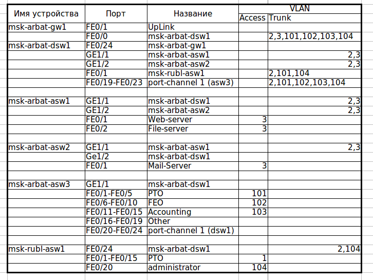
Итак, переходим к практике. Для начала внесем некоторые изменения в топологию — добавим избыточные линки. Учитывая сказанное в самом начале, вполне логично было бы сделать это в московском офисе в районе серверов — там у нас свич msk-arbat-asw2 доступен только через asw1, что не есть гуд. Мы отбираем (пока, позже возместим эту потерю) гигабитный линк, который идет от msk-arbat-dsw1 к msk-arbat-asw3, и подключаем через него asw2. Asw3 пока подключаем в порт Fa0/2 dsw1. Перенастраиваем транки:
msk-arbat-dsw1(config)#interface gi1/2
msk-arbat-dsw1(config-if)#description msk-arbat-asw2
msk-arbat-dsw1(config-if)#switchport trunk allowed vlan 2,3
msk-arbat-dsw1(config-if)#int fa0/2
msk-arbat-dsw1(config-if)#description msk-arbat-asw3
msk-arbat-dsw1(config-if)#switchport mode trunk
msk-arbat-dsw1(config-if)#switchport trunk allowed vlan 2,101-104msk-arbat-asw2(config)#int gi1/2
msk-arbat-asw2(config-if)#description msk-arbat-dsw1
msk-arbat-asw2(config-if)#switchport mode trunk
msk-arbat-asw2(config-if)#switchport trunk allowed vlan 2,3
msk-arbat-asw2(config-if)#no shutdown
Не забываем вносить все изменения в документацию!
Скачать актуальную версию документа.
Теперь посмотрим, как в данный момент у нас самонастроился STP. Нас интересует только VLAN0003, где у нас, судя по схеме, петля.
msk-arbat-dsw1>en
msk-arbat-dsw1#show spanning-tree vlan 3
Разбираем по полочкам вывод команды
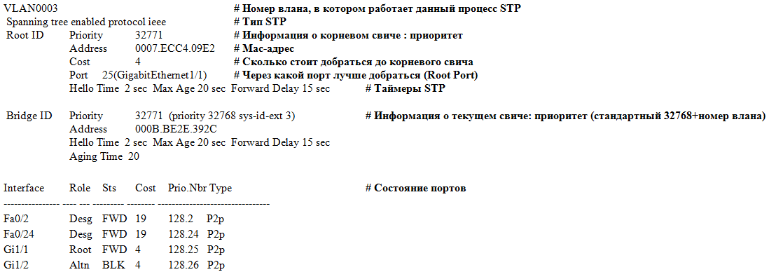
Итак, какую информацию мы можем получить? Так как по умолчанию на современных цисках работает PVST+ (т.е. для каждого влана свой процесс STP), и у нас есть более одного влана, выводится информация по каждому влану в отдельности, каждая запись предваряется номером влана. Затем идет вид STP: ieee значит PVST, rstp — Rapid PVST, mstp то и значит. Затем идет секция с информацией о корневом свиче: установленный на нем приоритет, его mac-адрес, стоимость пути от текущего свича до корневого, порт, который был выбран в качестве корневого (имеет лучшую стоимость), а также настройки таймеров STP. Далее- секция с той же информацией о текущем свиче (с которого выполняли команду). Затем- таблица состояния портов, которая состоит из следующих колонок (слева направо):
- собственно, порт
- его роль (Root- корневой порт, Desg- назначенный порт, Altn- дополнительный, Back- резервный)
- его статус (FWD- работает, BLK- заблокирован, LIS- прослушивание, LRN- обучение)
- стоимость маршрута до корневого свича
- Port ID в формате: приоритет порта.номер порта
- тип соединения
Итак, мы видим, что Gi1/1 корневой порт, это дает некоторую вероятность того, что на другом конце линка корневой свич. Смотрим по схеме, куда ведет линк: ага, некий msk-arbat-asw1.
msk-arbat-asw1#show spanning-tree vlan 3
И что же мы видим?
VLAN0003
 Spanning tree enabled protocol ieee
 Root ID    Priority    32771
            Address     0007.ECC4.09E2
            This bridge is the root
            Hello Time  2 sec  Max Age 20 sec  Forward Delay 15 sec
Вот он, наш корневой свич для VLAN0003.
А теперь посмотрим на схему. Ранее, мы увидели в состоянии портов, что dsw1 блокирует порт Gi1/2, разрывая таким образом петлю. Но является ли это оптимальным решением? Нет, конечно. Сейчас наша новая сеть работает точь-в-точь как старая- трафик от asw2 идет только через asw1. Выбор корневого маршрутизатора никогда не нужно оставлять на совесть глупого STP. Исходя из схемы, наиболее оптимальным будет выбор в качестве корневого свича dsw1- таким образом, STP заблокирует линк между asw1 и asw2. Теперь это все надо объяснить недалекому протоколу. А для него главное что? Bridge ID. И он неслучайно складывается из двух чисел. Приоритет- это как раз то слагаемое, которое отдано на откуп сетевому инженеру, чтобы он мог повлиять на результат выбора корневого свича. Итак, наша задача сводится к тому, чтобы уменьшить (меньше-лучше, думает STP) приоритет нужного свича, чтобы он стал Root Bridge. Есть два пути:
1) вручную установить приоритет, заведомо меньший, чем текущий:
msk-arbat-dsw1>enable
msk-arbat-dsw1#configure terminal
msk-arbat-dsw1(config)#spanning-tree vlan 3 priority?
<0-61440> bridge priority in increments of 4096
msk-arbat-dsw1(config)#spanning-tree vlan 3 priority 4096
Теперь он стал корневым для влана 3, так как имеет меньший Bridge ID:
msk-arbat-dsw1#show spanning-tree vlan 3
VLAN0003
Spanning tree enabled protocol ieee
Root ID Priority 4099
Address 000B.BE2E.392C
This bridge is the root
Hello Time 2 sec Max Age 20 sec Forward Delay 15 sec
2) дать умной железке решить все за тебя:
msk-arbat-dsw1(config)#spanning-tree vlan 3 root primary
Проверяем:
msk-arbat-dsw1#show spanning-tree vlan 3
VLAN0003
Spanning tree enabled protocol ieee
Root ID Priority 24579
Address 000B.BE2E.392C
This bridge is the root
Hello Time 2 sec Max Age 20 sec Forward Delay 15 sec
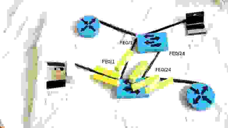
Мы видим, что железка поставила какой-то странный приоритет. Откуда взялась эта круглая цифра, спросите вы? А все просто- STP смотрит минимальный приоритет (т.е. тот, который у корневого свича), и уменьшает его на два шага инкремента (который составляет 4096, т.е. в итоге 8192). Почему на два? А чтобы была возможность на другом свиче дать команду spanning-tree vlan n root secondary (назначает приоритет=приоритет корневого-4096), что позволит нам быть уверенными, что, если с текущим корневым свичом что-то произойдет, его функции перейдут к этому, “запасному”. Вероятно, вы уже видите на схеме, как лампочка на линке между asw2 и asw1 пожелтела? Это STP разорвал петлю. Причем именно в том месте, в котором мы хотели. Sweet! Зайдем проверим: лампочка — это лампочка, а конфиг — это факт.
msk-arbat-asw2#show spanning-tree vlan 3
VLAN0003
 Spanning tree enabled protocol ieee
 Root ID    Priority    24579
            Address     000B.BE2E.392C
            Cost        4
            Port        26(GigabitEthernet1/2)
            Hello Time  2 sec  Max Age 20 sec  Forward Delay 15 sec

 Bridge ID  Priority    32771  (priority 32768 sys-id-ext 3)
            Address     000A.F385.D799
            Hello Time  2 sec  Max Age 20 sec  Forward Delay 15 sec
            Aging Time  20

Interface        Role    Sts    Cost      Prio.Nbr Type
---------------- ---- --- --------- -------- --------------------------------
Fa0/1            Desg    FWD    19        128.1    P2p
Gi1/1            Altn    BLK    4         128.25   P2p
Gi1/2            Root    FWD    4         128.26   P2p
Теперь полюбуемся, как работает STP: заходим в командную строку на ноутбуке PTO1 и начинаем бесконечно пинговать наш почтовый сервер (172.16.0.4). Пинг сейчас идет по маршруту ноутбук-asw3-dsw1-gw1-dsw1(ну тут понятно, зачем он крюк делает — они из разных вланов)-asw2-сервер. А теперь поработаем Годзиллой из SimСity: нарушим связь между dsw1 и asw2, вырвав провод из порта (замечаем время, нужное для пересчета дерева).
Пинги пропадают, STP берется за дело, и за каких-то 30 секунд коннект восстанавливается. Годзиллу прогнали, пожары потушили, связь починили, втыкаем провод обратно. Пинги опять пропадают на 30 секунд! Мда-а-а, как-то не очень быстро, особенно если представить, что это происходит, например, в процессинговом центре какого-нибудь банка.
Но у нас есть ответ медленному PVST+! И ответ этот — Быстрый PVST+ (так и называется, это не шутка: Rapid-PVST). Посмотрим, что он нам дает. Меняем тип STP на всех свичах в москве командой конфигурационного режима: spanning-tree mode rapid-pvst
Снова запускаем пинг, вызываем Годзиллу… Эй, где пропавшие пинги? Их нет, это же Rapid-PVST. Как вы, наверное, помните из теоретической части, эта реализация STP, так сказать, “подстилает соломку” на случай падения основного линка, и переключается на дополнительный (alternate) порт очень быстро, что мы и наблюдали. Ладно, втыкаем провод обратно. Один потерянный пинг. Неплохо по сравнению с 6-8, да?
EtherChannel
Помните, мы отобрали у офисных работников их гигабитный линк и отдали его в пользу серверов? Сейчас они, бедняжки, сидят, на каких-то ста мегабитах, прошлый век! Попробуем расширить канал, и на помощь призовем EtherChannel. В данный момент у нас соединение идет от fa0/2 dsw1 на Gi1/1 asw3, отключаем провод. Смотрим, какие порты можем использовать на asw3: ага, fa0/20-24 свободны, кажется. Вот их и возьмем. Со стороны dsw1 пусть будут fa0/19-23. Соединяем порты для EtherChannel между собой. На asw3 у нас на интерфейсах что-то настроено, обычно в таких случаях используется команда конфигурационного режима default interface range fa0/20-24, сбрасывающая настройки порта (или портов, как в нашем случае) в дефолтные. Packet tracer, увы, не знает такой хорошей команды, поэтому в ручном режиме убираем каждую настройку, и тушим порты (лучше это сделать, во избежание проблем)
msk-arbat-asw3(config)#interface range fa0/20-24
msk-arbat-asw3(config-if-range)#no description
msk-arbat-asw3(config-if-range)#no switchport access vlan
msk-arbat-asw3(config-if-range)#no switchport mode
msk-arbat-asw3(config-if-range)#shutdown
ну а теперь волшебная команда
msk-arbat-asw3(config-if-range)#channel-group 1 mode on
то же самое на dsw1:
msk-arbat-dsw1(config)#interface range fa0/19-23
msk-arbat-dsw1(config-if-range)#channel-group 1 mode on
поднимаем интерфейсы asw3, и вуаля: вот он, наш EtherChannel, раскинулся аж на 5 физических линков. В конфиге он будет отражен как interface Port-channel 1. Настраиваем транк (повторить для dsw1):
msk-arbat-asw3(config)#int port-channel 1
msk-arbat-asw3(config-if)#switchport mode trunk
msk-arbat-asw3(config-if)#switchport trunk allowed vlan 2,101-104
Как и с STP, есть некая трудность при работе с etherchannel в Packet Tracer’e. Настроить-то мы, в принципе, можем по вышеописанному сценарию, но вот проверка работоспособности под большим вопросом: после отключения одного из портов в группе, трафик перетекает на следующий, но как только вы вырубаете второй порт — связь теряется и не восстанавливается даже после включения портов.
Отчасти в силу только что озвученной причины, отчасти из-за ограниченности ресурсов мы не сможем раскрыть в полной мере эти вопросы и посему оставляем бОльшую часть на самоизучение.
Материалы выпуска
Новый план коммутации
Файл PT с лабораторной.
Конфигурация устройств
STP или STP
Безопасность канального уровня
Агрегация каналов
По сложившейся традиции все неотвеченные вопросы безымянными читателями хабра задаются в блоге цикла в ЖЖ.
За видео и помощь в подготовке статьи спасибо eucariot
Table Of Contents
Spanning Tree Protocol
Understanding Spanning Tree Protocol
STP Overview
Bridge Interoperability
Bridge Protocol Data Units
Election of the Spanning-Tree Root
Spanning-Tree Timers
Creating the Spanning-Tree Topology
Spanning-Tree Interface States
Blocking State
Listening State
Learning State
Forwarding State
Disabled State
Configuring STP Features
Default STP Configuration
Configuring STP Settings
STP Configuration Examples
Root Device Without VLANs
Non-Root Bridge Without VLANs
Root Device with VLANs
Non-Root Bridge with VLANs
Displaying Spanning-Tree Status
Spanning Tree Protocol
This document descibes Spanning Tree Protocol (STP) in a wireless environment.
Understanding Spanning Tree Protocol
This section describes how spanning-tree features work.
STP Overview
STP is a Layer 2 link management protocol that provides path redundancy while preventing loops in the network. For a Layer 2 network to function properly, only one active path can exist between any two stations. Spanning-tree operation is transparent to end stations, which cannot detect whether they are connected to a single LAN segment or to a LAN of multiple segments.
When you create fault-tolerant internetworks, you must have a loop-free path between all nodes in a network. The spanning-tree algorithm calculates the best loop-free path throughout a Layer 2 network. Infrastructure devices such as wireless bridges and switches send and receive spanning-tree frames, called bridge protocol data units (BPDUs), at regular intervals. The devices do not forward these frames but use them to construct a loop-free path.
Multiple active paths among end stations cause loops in the network. If a loop exists in the network, end stations might receive duplicate messages. Infrastructure devices might also learn end-station MAC addresses on multiple Layer 2 interfaces. These conditions result in an insecure network.
STP defines a tree with a root device and a loop-free path from the root to all infrastructure devices in the Layer 2 network.

Note ![]() In discussions about STP, the term root is used to describe two concepts: the bridge on the network that serves as a central point in the spanning tree is called the root device, and the port on each device that provides the most efficient path to the device is called the root port. These meanings are separate. A bridge whose role in radio network setting is root device does not necessarily become the root device in the spanning tree. In this chapter, the root device in the spanning tree is called the spanning-tree root.
In discussions about STP, the term root is used to describe two concepts: the bridge on the network that serves as a central point in the spanning tree is called the root device, and the port on each device that provides the most efficient path to the device is called the root port. These meanings are separate. A bridge whose role in radio network setting is root device does not necessarily become the root device in the spanning tree. In this chapter, the root device in the spanning tree is called the spanning-tree root.
STP forces redundant data paths into a standby (blocked) state. If a network segment in the spanning tree fails and a redundant path exists, the spanning-tree algorithm recalculates the spanning-tree topology and activates the standby path.
When two interfaces are part of a loop, the spanning-tree port priority and path cost settings determine which interface is put in the forwarding state and which is put in the blocking state. The port priority value represents the location of an interface in the network topology and how well it is located to pass traffic. The path cost value represents media speed.
The bridge supports both per-VLAN spanning tree (PVST) and a single 802.1q spanning tree without VLANs. The bridge cannot run 802.1s multiple spanning tree (MST) or 802.1d Common Spanning Tree, which map multiple VLANs into a one-instance spanning tree.
The bridge maintains a separate spanning-tree instance for each active VLAN configured on it. A bridge ID, consisting of the bridge priority and the MAC address, is associated with each instance. For each VLAN, the bridge with the lowest bridge ID becomes the spanning-tree root for that VLAN.
Bridge Interoperability
Cisco bridges are interoperable when STP is enabled and no VLANs are configured. This configuration is the only one possible, for the following reasons:
•![]() When STP is disabled, the bridge acts as an access point and disallows association of non-root bridge.
When STP is disabled, the bridge acts as an access point and disallows association of non-root bridge.
•![]() The bridge has a single instance of STP in non-VLAN configurations and multiple instances of STP in VLAN configurations.
The bridge has a single instance of STP in non-VLAN configurations and multiple instances of STP in VLAN configurations.
•![]() Incompatibilities between single and multiple instances of STP can cause inconsistent blocking of traffic when VLANs are configured. When the native VLAN is blocked, bridge flapping can occur.
Incompatibilities between single and multiple instances of STP can cause inconsistent blocking of traffic when VLANs are configured. When the native VLAN is blocked, bridge flapping can occur.
Therefore, the best configuration for STP interoperability is to have the bridge STP feature enabled and VLANs not configured.
Note ![]() When Cisco bridges are configured as workgroup bridges, they can operate with STP disabled and allow for associations with access points. However, this configuration is not technically a bridge-to-bridge scenario.
When Cisco bridges are configured as workgroup bridges, they can operate with STP disabled and allow for associations with access points. However, this configuration is not technically a bridge-to-bridge scenario.
Bridge Protocol Data Units
The stable, active spanning-tree topology of a network is determined by the following factors:
•![]() The unique bridge ID (wireless bridge priority and MAC address) associated with each VLAN on each wireless bridge
The unique bridge ID (wireless bridge priority and MAC address) associated with each VLAN on each wireless bridge
•![]() The spanning-tree path cost to the spanning-tree root
The spanning-tree path cost to the spanning-tree root
•![]() The port identifier (port priority and MAC address) associated with each Layer 2 interface
The port identifier (port priority and MAC address) associated with each Layer 2 interface
When the bridges in a network are powered up, each bridge functions as the STP root. The bridges send configuration BPDUs through the Ethernet and radio ports. The BPDUs communicate and compute the spanning-tree topology. Each configuration BPDU contains this information:
•![]() The unique bridge ID of the wireless bridge that the sending bridge identifies as the spanning-tree root
The unique bridge ID of the wireless bridge that the sending bridge identifies as the spanning-tree root
•![]() The spanning-tree path cost to the root
The spanning-tree path cost to the root
•![]() The bridge ID of the sending bridge
The bridge ID of the sending bridge
•![]() Message age
Message age
•![]() The identifier of the sending interface
The identifier of the sending interface
•![]() Values for the hello, forward delay, and max-age protocol timers
Values for the hello, forward delay, and max-age protocol timers
When a bridge receives a configuration BPDU that contains information superior (lower bridge ID, lower path cost, and so forth), it stores the information for that port. If this BPDU is received on the root port of the bridge, the bridge also forwards it with an updated message to all attached LANs for which it is the designated bridge.
If a bridge receives a configuration BPDU that contains inferior information to that currently stored for that port, it discards the BPDU. If the bridge is a designated bridge for the LAN from which the inferior BPDU was received, it sends that LAN a BPDU containing the up-to-date information stored for that port. In this way, inferior information is discarded, and superior information is propagated on the network.
A BPDU exchange results in these actions:
•![]() One bridge is elected as the spanning-tree root.
One bridge is elected as the spanning-tree root.
•![]() A root port is selected for each bridge (except the spanning-tree root). This port provides the best path (lowest cost) when the bridge forwards packets to the spanning-tree root.
A root port is selected for each bridge (except the spanning-tree root). This port provides the best path (lowest cost) when the bridge forwards packets to the spanning-tree root.
•![]() The shortest distance to the spanning-tree root is calculated for each bridge based on the path cost.
The shortest distance to the spanning-tree root is calculated for each bridge based on the path cost.
•![]() A designated bridge for each LAN segment is selected. The designated bridge incurs the lowest path cost when forwarding packets from that LAN to the spanning-tree root. The port through which the designated bridge is attached to the LAN is called the designated port.
A designated bridge for each LAN segment is selected. The designated bridge incurs the lowest path cost when forwarding packets from that LAN to the spanning-tree root. The port through which the designated bridge is attached to the LAN is called the designated port.
•![]() Interfaces that are included in the spanning-tree instance are selected. Root ports and designated ports are put in the forwarding state.
Interfaces that are included in the spanning-tree instance are selected. Root ports and designated ports are put in the forwarding state.
•![]() All interfaces that are not included in the spanning tree are blocked.
All interfaces that are not included in the spanning tree are blocked.
Election of the Spanning-Tree Root
All bridges in the Layer 2 network that are participating in STP gather information about other bridges in the network by exchanging BPDU data messages. This message exchange results in these actions:
•![]() The election of a unique spanning-tree root for each spanning-tree instance
The election of a unique spanning-tree root for each spanning-tree instance
•![]() The election of a designated bridge for every LAN segment
The election of a designated bridge for every LAN segment
•![]() The removal of loops in the network by blocking Layer 2 interfaces connected to redundant links
The removal of loops in the network by blocking Layer 2 interfaces connected to redundant links
For each VLAN, the bridge with the highest bridge priority (the lowest numerical priority value) is elected as the spanning-tree root. If all bridges are configured with the default priority (32768), the bridge with the lowest MAC address in the VLAN becomes the spanning-tree root. The bridge priority value occupies the most significant bits of the bridge ID.
When you change the bridge priority value, you change the probability that the bridge will be elected as the root device. Configuring a higher value decreases the probability; a lower value increases the probability.
The spanning-tree root is the logical center of the spanning-tree topology. Paths that are not needed to reach the spanning-tree root from anywhere in the network are placed in the spanning-tree blocking mode.
BPDUs contain information about the sending bridge and its ports, including bridge and MAC addresses, bridge priority, port priority, and path cost. STP uses this information to elect the spanning-tree root and root port for the network and the root port and designated port for each LAN segment.
Spanning-Tree Timers
Table 1 describes the timers that affect the entire spanning-tree performance.
|
Variable |
Description |
|---|---|
|
Hello timer |
Determines how often the bridge broadcasts hello messages to other bridges. |
|
Forward-delay timer |
Determines how long each of the listening and learning states last before the interface begins forwarding. |
|
Maximum-age timer |
Determines the amount of time the bridge stores protocol information received on an interface. |
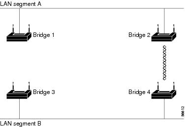
Creating the Spanning-Tree Topology
In Figure 1, bridge 4 is elected as the spanning-tree root, under the assumption that the priority of all the bridges is set to the default (32768) and bridge 4 has the lowest MAC address. However, because of traffic patterns, number of forwarding interfaces, or link types, bridge 4 might not be the ideal spanning-tree root. By increasing the priority (lowering the numerical value) of the ideal bridge so that it becomes the spanning-tree root, you force a spanning-tree recalculation to form a new topology with the ideal bridge as the spanning-tree root.
Figure 1 Spanning-Tree Topology
Spanning-Tree Interface States
Propagation delays can occur when protocol information passes through a wireless LAN. As a result, topology changes can take place at different times and at different places in the network. When an interface transitions directly from nonparticipation in the spanning-tree topology to the forwarding state, it can create temporary data loops. Interfaces must wait for new topology information to propagate through the LAN before starting to forward frames. They must allow the frame lifetime to expire for forwarded frames that have used the old topology.
Each interface on a bridge using spanning tree exists in one of these states:
•![]() Blocking—The interface does not participate in frame forwarding.
Blocking—The interface does not participate in frame forwarding.
•![]() Listening—The first transitional state after the blocking state, in which the spanning tree determines that the interface should participate in frame forwarding.
Listening—The first transitional state after the blocking state, in which the spanning tree determines that the interface should participate in frame forwarding.
•![]() Learning—The interface prepares to participate in frame forwarding.
Learning—The interface prepares to participate in frame forwarding.
•![]() Forwarding—The interface forwards frames.
Forwarding—The interface forwards frames.
•![]() Disabled—The interface is not participating in spanning tree because there is a port shutdown, there is no link on the port, or no spanning-tree instance is running on the port.
Disabled—The interface is not participating in spanning tree because there is a port shutdown, there is no link on the port, or no spanning-tree instance is running on the port.
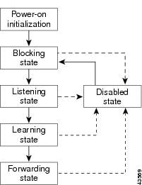
An interface moves through these states:
•![]() From initialization to blocking
From initialization to blocking
•![]() From blocking to listening or to disabled
From blocking to listening or to disabled
•![]() From listening to learning or to disabled
From listening to learning or to disabled
•![]() From learning to forwarding or to disabled
From learning to forwarding or to disabled
•![]() From forwarding to disabled
From forwarding to disabled
Figure 2 illustrates how an interface moves through the states.
Figure 2 Spanning-Tree Interface States
When you enable STP on the bridge, the Ethernet and radio interfaces go through the blocking state and the transitory states of listening and learning. STP stabilizes each interface at the forwarding or blocking state.
When the spanning-tree algorithm places a Layer 2 interface in the forwarding state, this process occurs:
1. ![]() The interface is in the listening state while STP waits for protocol information to transition the interface to the blocking state.
The interface is in the listening state while STP waits for protocol information to transition the interface to the blocking state.
2. ![]() While STP waits the forward-delay timer to expire, it moves the interface to the learning state and resets the forward-delay timer.
While STP waits the forward-delay timer to expire, it moves the interface to the learning state and resets the forward-delay timer.
3. ![]() In the learning state, the interface continues to block frame forwarding as the bridge learns end-station location information for the forwarding database.
In the learning state, the interface continues to block frame forwarding as the bridge learns end-station location information for the forwarding database.
4. ![]() When the forward-delay timer expires, STP moves the interface to the forwarding state, where both learning and frame forwarding are enabled.
When the forward-delay timer expires, STP moves the interface to the forwarding state, where both learning and frame forwarding are enabled.
Blocking State
An interface in the blocking state does not participate in frame forwarding. After initialization, a BPDU is sent to the bridge’s Ethernet and radio ports. A bridge initially functions as the spanning-tree root until it exchanges BPDUs with other bridges. This exchange establishes which bridge in the network is the spanning-tree root. If there is only one bridge in the network, no exchange occurs, the forward-delay timer expires, and the interfaces move to the listening state. An interface always enters the blocking state when you enable STP.
An interface in the blocking state performs as follows:
•![]() Discards frames received on the port
Discards frames received on the port
•![]() Does not learn addresses
Does not learn addresses
•![]() Receives BPDUs
Receives BPDUs
Note ![]() If a port is blocked, some broadcast or multicast packets can reach a forwarding port on the bridge and cause the bridging logic to switch the blocked port into listening state momentarily before the packets are dropped at the blocked port.
If a port is blocked, some broadcast or multicast packets can reach a forwarding port on the bridge and cause the bridging logic to switch the blocked port into listening state momentarily before the packets are dropped at the blocked port.
Listening State
The listening state is the first state an interface enters after the blocking state. The interface enters this state when STP determines that the interface should participate in frame forwarding.
An interface in the listening state performs as follows:
•![]() Discards frames received on the port
Discards frames received on the port
•![]() Does not learn addresses
Does not learn addresses
•![]() Receives BPDUs
Receives BPDUs
Learning State
An interface in the learning state prepares to participate in frame forwarding. The interface enters the learning state from the listening state.
An interface in the learning state performs as follows:
•![]() Discards frames received on the port
Discards frames received on the port
•![]() Learns addresses
Learns addresses
•![]() Receives BPDUs
Receives BPDUs
Forwarding State
An interface in the forwarding state forwards frames. The interface enters the forwarding state from the learning state.
An interface in the forwarding state performs as follows:
•![]() Receives and forwards frames received on the port
Receives and forwards frames received on the port
•![]() Learns addresses
Learns addresses
•![]() Receives BPDUs
Receives BPDUs
Disabled State
An interface in the disabled state does not participate in frame forwarding or in the spanning tree. An interface in the disabled state is nonoperational.
A disabled interface performs as follows:
•![]() Discards frames received on the port
Discards frames received on the port
•![]() Does not learn addresses
Does not learn addresses
•![]() Does not receive BPDUs
Does not receive BPDUs
Configuring STP Features
You complete three major steps to configure STP on the WMIC:
1. ![]() If necessary, assign interfaces and subinterfaces to bridge groups
If necessary, assign interfaces and subinterfaces to bridge groups
2. ![]() Enable STP for each bridge group
Enable STP for each bridge group
3. ![]() Set the STP priority for each bridge group
Set the STP priority for each bridge group
These sections provide information on STP configuration:
•![]() Default STP Configuration
Default STP Configuration
•![]() Configuring STP Settings
Configuring STP Settings
•![]() STP Configuration Examples
STP Configuration Examples
Default STP Configuration
STP is disabled by default. Table 2 lists the default STP settings when you enable STP.
|
Setting |
Default Value |
|---|---|
|
bridge priority |
32768 |
|
bridge max age |
20 |
|
bridge hello time |
2 |
|
bridge forward delay |
15 |
|
Ethernet port path cost |
19 |
|
Ethernet port priority |
128 |
|
radio port path cost |
33 |
|
radio port priority |
128 |
The radio and Ethernet interfaces and the native VLAN on the bridge are assigned to bridge group 1 by default. When you enable STP and assign a priority on bridge group 1, STP is enabled on the radio and Ethernet interfaces and on the primary VLAN, and those interfaces adopt the priority assigned to bridge group 1. You can create bridge groups for subinterfaces and assign different STP settings to those bridge groups.
Configuring STP Settings
To configure STP on the WMIC, follow these steps, beginning in privileged EXEC mode:
|
Command |
Purpose |
|
|---|---|---|
|
Step 1 |
configure terminal |
Enters global configuration mode. |
|
Step 2 |
interface {dot11radio port | fastethernet port } |
Enters interface configuration mode for radio or Ethernet interfaces or subinterfaces. |
|
Step 3 |
bridge-group number |
Assigns the interface to a bridge group. You can number your bridge groups from 1 to 255. |
|
Step 4 |
no bridge-group number spanning-disabled |
Counteracts the command that automatically disables STP for a bridge group. (STP is later enabled on the interface when you enter the bridge n protocol ieee command.) |
|
Step 5 |
exit |
Returns to global configuration mode. |
|
Step 6 |
bridge number protocol ieee |
Enables STP for the bridge group. You must enable STP on each bridge group that you create with bridge-group commands. |
|
Step 7 |
bridge number priority priority |
(Optional) Assigns a priority to a bridge group. The lower the priority, the more likely it is that the bridge becomes the spanning-tree root. |
|
Step 8 |
end |
Returns to privileged EXEC mode. |
|
Step 9 |
show spanning-tree bridge |
Verifies your entries. |
|
Step 10 |
copy running-config startup-config |
(Optional) Saves your entries in the configuration file. |
STP Configuration Examples
These configuration examples show how to enable STP on root and non-root bridges with and without VLANs:
•![]() Root Device Without VLANs
Root Device Without VLANs
•![]() Non-Root Bridge Without VLANs
Non-Root Bridge Without VLANs
•![]() Root Device with VLANs
Root Device with VLANs
•![]() Non-Root Bridge with VLANs
Non-Root Bridge with VLANs
Root Device Without VLANs
This example shows the configuration of a root device with no VLANs configured and with STP enabled:
hostname master-bridge-south
speed basic-6.0 9.0 12.0 18.0 24.0 36.0 48.0 54.0
ip address 1.4.64.23 255.255.0.0
ip default-gateway 1.4.0.1
Non-Root Bridge Without VLANs
This example shows the configuration of a non-root bridge with STP enabled and no VLANs configured:
hostname client-bridge-north
speed basic-6.0 9.0 12.0 18.0 24.0 36.0 48.0 54.0
bridge-group 1 path-cost 40
ip address 1.4.64.24 255.255.0.0
Root Device with VLANs
This example shows the configuration of a root device with VLANs configured with STP enabled:
hostname master-bridge-hq
ip ssh authentication-retries 3
speed basic-6.0 9.0 12.0 18.0 24.0 36.0 48.0 54.0
encapsulation dot1Q 1 native
bridge-group 3 path-cost 500
interface FastEthernet0.1
encapsulation dot1Q 1 native
interface FastEthernet0.2
interface FastEthernet0.3
ip address 1.4.64.23 255.255.0.0
ip default-gateway 1.4.0.1
Non-Root Bridge with VLANs
This example shows the configuration of a non-root bridge with VLANs configured with STP enabled:
hostname client-bridge-remote
ip ssh authentication-retries 3
speed basic-6.0 9.0 12.0 18.0 24.0 36.0 48.0 54.0
encapsulation dot1Q 1 native
interface FastEthernet0.1
encapsulation dot1Q 1 native
interface FastEthernet0.2
interface FastEthernet0.3
bridge-group 3 path-cost 400
ip address 1.4.64.24 255.255.0.0
Displaying Spanning-Tree Status
To display the spanning-tree status, use one or more of the commands in Table 3 in privileged EXEC mode:
|
Command |
Purpose |
|---|---|
|
show spanning-tree |
Displays information on your network’s spanning tree. |
|
show spanning-tree blocked-ports |
Displays a list of blocked ports on this device. |
|
show spanning-tree bridge |
Displays status and configuration of this bridge. |
|
show spanning-tree active |
Displays spanning-tree information on active interfaces only. |
|
show spanning-tree root |
Displays a detailed summary of information on the spanning-tree root. |
|
show spanning-tree interface interface-id |
Displays spanning-tree information for the specified interface. |
|
show spanning-tree summary [totals] |
Displays a summary of port states or displays the total lines of the STP state section. |
For information about other keywords for the show spanning-tree privileged EXEC command, refer to the Cisco IOS Command Reference for Cisco Access Points and Bridges.
The Spanning Tree Protocol (STP) is a network protocol that builds a loop-free logical topology for Ethernet networks. The basic function of STP is to prevent bridge loops and the broadcast radiation that results from them. Spanning tree also allows a network design to include backup links providing fault tolerance if an active link fails.
As the name suggests, STP creates a spanning tree that characterizes the relationship of nodes within a network of connected layer-2 bridges, and disables those links that are not part of the spanning tree, leaving a single active path between any two network nodes. STP is based on an algorithm that was invented by Radia Perlman while she was working for Digital Equipment Corporation.[1][2]
In 2001, the IEEE introduced Rapid Spanning Tree Protocol (RSTP) as 802.1w. RSTP provides significantly faster recovery in response to network changes or failures, introducing new convergence behaviors and bridge port roles to do this. RSTP was designed to be backwards-compatible with standard STP.
STP was originally standardized as IEEE 802.1D but the functionality of spanning tree (802.1D), rapid spanning tree (802.1w), and multiple spanning tree (802.1s) has since been incorporated into IEEE 802.1Q-2014.[3]
While STP is still in use today, in most modern networks its primary use is as a loop-protection mechanism rather than a fault tolerance mechanism.[citation needed] Link aggregation protocols such as LACP will bond two or more links to provide fault tolerance while simultaneously increasing overall link capacity.
Protocol operation[edit]

Switches with Spanning Tree Protocol implementation in a local area network (LAN). One switch is the STP root bridge. All switch ports that connect a link between two switches are either a root port (RP), a designated port (DP), or a blocked port (BP).
After link failure the spanning tree algorithm computes and spans new least-cost tree.
Switches with Spanning Tree Protocol implementation in a local area network (LAN)
The need for the Spanning Tree Protocol (STP) arose because switches in local area networks (LANs) are often interconnected using redundant links to improve resilience should one connection fail.[4]: 386 However, this connection configuration creates a switching loop resulting in broadcast radiations and MAC table instability.[4]: 388 If redundant links are used to connect switches, then switching loops need to be avoided.[4]: 385
To avoid the problems associated with redundant links in a switched LAN, STP is implemented on switches to monitor the network topology. Every link between switches, and in particular redundant links, are catalogued. The spanning-tree algorithm then blocks forwarding on redundant links by setting up one preferred link between switches in the LAN. This preferred link is used for all Ethernet frames unless it fails, in which case a non-preferred redundant link is enabled. When implemented in a network, STP designates one layer-2 switch as root bridge. All switches then select their best connection towards the root bridge for forwarding and block other redundant links. All switches constantly communicate with their neighbors in the LAN using bridge protocol data units (BPDUs).[4]: 388
Provided there is more than one link between two switches, the STP root bridge calculates the cost of each path based on bandwidth. STP will select the path with the lowest cost, that is the highest bandwidth, as the preferred link. STP will enable this preferred link as the only path to be used for Ethernet frames between the two switches, and disable all other possible links by designating the switch ports that connect the preferred path as root port.[4]: 393
After STP enabled switches in a LAN have elected the root bridge, all non-root bridges assign one of their ports as root port. This is either the port that connects the switch to the root bridge, or if there are several paths, the port with the preferred path as calculated by the root bridge. Because not all switches are directly connected to the root bridge they communicate amongst each other using STP BPDUs. Each switch adds the cost of its own path to the cost received from the neighboring switches to determine the total cost of a given path to the root bridge. Once the cost of all possible paths to the root bridge have been added up, each switch assigns a port as root port which connects to the path with the lowest cost, or highest bandwidth, that will eventually lead to the root bridge.[4]: 394
Path cost[edit]
| Data rate (link bandwidth) |
Original STP cost (802.1D-1998) |
RSTP/MSTP cost (recommended value)[3]: 503 |
|---|---|---|
| 4 Mbit/s | 250 | 5,000,000 |
| 10 Mbit/s | 100 | 2,000,000 |
| 16 Mbit/s | 62 | 1,250,000 |
| 100 Mbit/s | 19 | 200,000 |
| 1 Gbit/s | 4 | 20,000 |
| 2 Gbit/s | 3 | 10,000 |
| 10 Gbit/s | 2 | 2,000 |
| 100 Gbit/s | N/A | 200 |
| 1 Tbit/s | N/A | 20 |
The STP path cost default was originally calculated by the formula 1 Gbit/s/bandwidth. When faster speeds became available, the default values were adjusted as otherwise speeds above 1 Gbit/s would have been indistinguishable by STP. Its successor RSTP uses a similar formula with a larger numerator: 20 Tbit/s/bandwidth. These formulas lead to the sample values in the table.[5]: 154
Port states[edit]
All switch ports in the LAN where STP is enabled are categorized.[4]: 388
- Blocking
- A port that would cause a switching loop if it were active. To prevent the use of looped paths, no user data is sent or received over a blocking port. BPDU data is still received in blocking state. A blocked port may go into forwarding mode if the other links in use fail and the spanning tree algorithm determines the port may transition to the forwarding state.
- Listening
- The switch processes BPDUs and awaits possible new information that would cause it to return to the blocking state. It does not populate the MAC table and it does not forward frames.
- Learning
- While the port does not yet forward frames, it does learn source addresses from frames received and adds them to the MAC table.
- Forwarding
- A port in normal operation receiving and forwarding frames. The port monitors incoming BPDUs that would indicate it should return to the blocking state to prevent a loop.
- Disabled
- A network administrator has manually disabled the switch port.
When a device is first attached to a switch port, it will not immediately start to forward data. It will instead go through a number of states while it processes BPDUs and determines the topology of the network. The port attached to a host such as a computer, printer or server always goes into the forwarding state, albeit after a delay of about 30 seconds while it goes through the listening and learning states. The time spent in the listening and learning states is determined by a value known as the forward delay (default 15 seconds and set by the root bridge). If another switch is connected, the port may remain in blocking mode if it is determined that it would cause a loop in the network. Topology change notification (TCN) BPDUs are used to inform other switches of port changes. TCNs are injected into the network by a non-root switch and propagated to the root. Upon receipt of the TCN, the root switch will set the topology change flag in its normal BPDUs. This flag is propagated to all other switches and instructs them to rapidly age out their forwarding table entries.
Configuration[edit]
Before configuring STP, the network topology should be carefully planned.[6] Basic configuration requires that STP be enabled on all switches in the LAN and the same version of STP chosen on each. The administrator may determine which switch will be the root bridge and configure the switches appropriately. If the root bridge goes down, the protocol will automatically assign a new root bridge based on bridge ID. If all switches have the same bridge ID, such as the default ID, and the root bridge goes down, a tie situation arises and the protocol will assign one switch as root bridge based on the switch MAC addresses. Once the switches have been assigned a bridge ID and the protocol has chosen the root bridge switch, the best path to the root bridge is calculated based on port cost, path cost and port priority.[7] Ultimately STP calculates the path cost on the basis of the bandwidth of a link, however links between switches may have the same bandwidth. Administrators can influence the protocol’s choice of the preferred path by configuring the port cost, the lower the port cost the more likely it is that the protocol will choose the connected link as root port for the preferred path.[8] The selection of how other switches in the topology choose their root port, or the least cost path to the root bridge, can be influenced by the port priority. The highest priority will mean the path will ultimately be less preferred. If all ports of a switch have the same priority, the port with the lowest number is chosen to forward frames.[9]
Root bridge and the bridge ID[edit]

The root bridge of the spanning tree is the bridge with the smallest (lowest) bridge ID. Each bridge has a configurable priority number and a MAC address; the bridge ID is the concatenation of the bridge priority and the MAC address. For example, the ID of a bridge with priority 32,768 and MAC 0200.0000.1111 is 32768.0200.0000.1111. The bridge priority default is 32,768 and can be configured only in multiples of 4096.[a] When comparing two bridge IDs, the priority portions are compared first and the MAC addresses are compared only if the priorities are equal. The switch with the lowest priority of all the switches will be the root; if there is a tie, then the switch with the lowest priority and lowest MAC address will be the root. For example, if switches A (MAC = 0200.0000.1111) and B (MAC = 0200.0000.2222) both have a priority of 32,768 then switch A will be selected as the root bridge.[b] If the network administrators would like switch B to become the root bridge, they must set its priority to be less than 32,768.[c]
Path to the root bridge[edit]
The sequence of events to determine the best received BPDU (which is the best path to the root) is:
- Lowest root bridge ID (BID) — Determines the root bridge.
- Lowest cost to the root bridge — Favors the upstream switch with the least cost to root
- Lowest sender bridge ID — Serves as a tiebreaker if multiple upstream switches have equal cost to root
- Lowest sender port ID — Serves as a tiebreaker if a switch has multiple (non-EtherChannel) links to a single upstream switch, where:
- Bridge ID = priority (4 bits) + locally assigned system ID extension (12 bits) + ID [MAC address] (48 bits); the default bridge priority is 32,768, and
- Port ID = priority (4 bits) + ID (Interface number) (12 bits); the default port priority is 128.
Tiebreakers[edit]

- Root ports
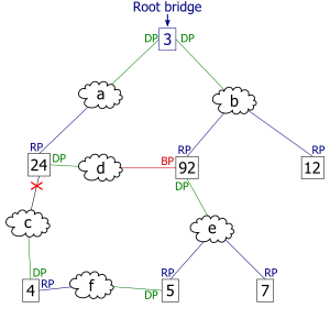
- When multiple paths from a bridge are least-cost paths, the chosen path uses the neighbor bridge with the lower bridge ID. The root port is thus the one connecting to the bridge with the lowest bridge ID. For example, in the figures, if switch 4 were connected to network segment d instead of segment f, there would be two paths of length 2 to the root, one path going through bridge 24 and the other through bridge 92. Because there are two least-cost paths, the lower bridge ID (24) would be used as the tiebreaker in choosing which path to use.
- Paths
- When more than one bridge on a segment leads to a least-cost path to the root, the bridge with the lower bridge ID is used to forward messages to the root. The port attaching that bridge to the network segment is the designated port for the segment. In the figures, there are two least-cost paths from network segment d to the root, one going through bridge 24 and the other through bridge 92. The lower bridge ID is 24, so the tiebreaker dictates that the designated port is the port through which network segment d is connected to bridge 24. If bridge IDs were equal, then the bridge with the lowest MAC address would have the designated port. In either case, the loser sets the port as being blocked.
- Designated ports
- When the root bridge has more than one port on a single LAN segment, the bridge ID is effectively tied, as are all root path costs (all equal zero). The port on that LAN segment with the lowest port ID becomes the designated port. It is put into forwarding mode while all other ports on the root bridge on that same LAN segment become non-designated ports and are put into blocking mode.[11] Not all bridge manufacturers follow this rule, instead making all root bridge ports designated ports, and putting them all in forwarding mode.[citation needed]
- Final tiebreaker
- In some cases, there may still be a tie, as when the root bridge has multiple active ports on the same LAN segment (see above) with equally low root path costs and bridge IDs, or, in other cases, multiple bridges are connected by multiple cables and multiple ports. In each case, a single bridge may have multiple candidates for its root port. In these cases, candidates for the root port have already received BPDUs offering equally-low (i.e. the «best») root path costs and equally-low (i.e. the «best») bridge IDs, and the final tiebreaker goes to the port that received the lowest (i.e. the «best») port priority ID, or port ID.[12]
Bridge protocol data units[edit]
The above rules describe one way of determining what spanning tree will be computed by the algorithm, but the rules as written require knowledge of the entire network. The bridges have to determine the root bridge and compute the port roles (root, designated, or blocked) with only the information that they have. To ensure that each bridge has enough information, the bridges use special data frames called bridge protocol data units (BPDU) to exchange information about bridge IDs and root path costs.
A bridge sends a BPDU frame using the unique MAC address of the port itself as a source address, and a destination address of the STP multicast address 01:80:C2:00:00:00.
There are two types of BPDUs in the original STP specification[5]: 63 (the Rapid Spanning Tree (RSTP) extension uses a specific RSTP BPDU):
- Configuration BPDU (CBPDU), used for spanning tree computation
- Topology change notification (TCN) BPDU, used to announce changes in the network topology
BPDUs are exchanged regularly (every 2 seconds by default) and enable switches to keep track of network changes and to start and stop forwarding at ports as required. To prevent the delay when connecting hosts to a switch and during some topology changes, Rapid STP was developed, which allows a switch port to rapidly transition into the forwarding state during these situations.
Bridge protocol data unit fields[edit]
IEEE 802.1D and IEEE 802.1aq BPDUs have the following format:
 1. Protocol ID:       2 bytes (0x0000 IEEE 802.1D)
 2. Version ID:        1 byte (0x00 Config & TCN / 0x02 RST / 0x03 MST / 0x04 SPT  BPDU)
 3. BPDU Type:         1 byte (0x00 STP Config BPDU, 0x80 TCN BPDU, 0x02 RST/MST Config BPDU)
 4. Flags:             1 byte
   bits  : usage
       1 : 0 or 1 for Topology Change
       2 : 0 (unused) or 1 for Proposal in RST/MST/SPT BPDU
     3–4 : 00 (unused) or
           01 for Port Role Alternate/Backup in RST/MST/SPT BPDU
           10 for Port Role Root in RST/MST/SPT BPDU
           11 for Port Role Designated in RST/MST/SPT BPDU
       5 : 0 (unused) or 1 for Learning in RST/MST/SPT BPDU
       6 : 0 (unused) or 1 for Forwarding in RST/MST/SPT BPDU
       7 : 0 (unused) or 1 for Agreement in RST/MST/SPT BPDU
       8 : 0 or 1 for Topology Change Acknowledgement
 5. Root ID:           8 bytes (CIST Root ID in MST/SPT BPDU)
   bits  : usage
     1–4 : Root Bridge Priority
    5–16 : Root Bridge System ID Extension
   17–64 : Root Bridge MAC Address
 6. Root Path Cost:    4 bytes (CIST External Path Cost in MST/SPT BPDU)
 7. Bridge ID:         8 bytes (CIST Regional Root ID in MST/SPT BPDU)
   bits  : usage
     1–4 : Bridge Priority
    5–16 : Bridge System ID Extension
   17–64 : Bridge MAC Address
  8. Port ID:          2 bytes
  9. Message Age:      2 bytes in 1/256 secs
 10. Max Age:          2 bytes in 1/256 secs
 11. Hello Time:       2 bytes in 1/256 secs
 12. Forward Delay:    2 bytes in 1/256 secs
 13. Version 1 Length: 1 byte (0x00 no ver 1 protocol info present. RST, MST, SPT BPDU only)
 14. Version 3 Length: 2 bytes (MST, SPT BPDU only)

 The TCN BPDU includes fields 1–3 only.
Spanning Tree Protocol standards[edit]
The first spanning tree protocol was invented in 1985 at the Digital Equipment Corporation by Radia Perlman.[1] In 1990, the IEEE published the first standard for the protocol as 802.1D,[13] based on the algorithm designed by Perlman. Subsequent versions were published in 1998[14] and 2004,[15] incorporating various extensions. The original Perlman-inspired Spanning Tree Protocol, called DEC STP, is not a standard and differs from the IEEE version in message format as well as timer settings. Some bridges implement both the IEEE and the DEC versions of the Spanning Tree Protocol, but their interworking can create issues for the network administrator.[16]
Different implementations of a standard are not guaranteed to interoperate, due for example to differences in default timer settings. The IEEE encourages vendors to provide a Protocol Implementation Conformance Statement, declaring which capabilities and options have been implemented,[15] to help users determine whether different implementations will interoperate correctly.
Rapid Spanning Tree Protocol[edit]
In 2001, the IEEE introduced Rapid Spanning Tree Protocol (RSTP) as IEEE 802.1w. RSTP was then incorporated into IEEE 802.1D-2004 making the original STP standard obsolete.[17] RSTP was designed to be backward-compatible with standard STP.
RSTP provides significantly faster spanning tree convergence after a topology change, introducing new convergence behaviors and bridge port roles to accomplish this. While STP can take 30 to 50 seconds to respond to a topology change, RSTP is typically able to respond to changes within 3 × hello times (default: 3 × 2 seconds) or within a few milliseconds of a physical link failure. The hello time is an important and configurable time interval that is used by RSTP for several purposes; its default value is 2 seconds.[18][19]
Rapid Spanning Tree operation[edit]
RSTP adds new bridge port roles in order to speed convergence following a link failure:
- Root — A forwarding port that is the best port from non-root bridge to root bridge
- Designated — A forwarding port for every LAN segment
- Alternate — An alternate path to the root bridge. This path is different from using the root port
- Backup — A backup/redundant path to a segment where another bridge port already connects
- Disabled — Not strictly part of STP, a network administrator can manually disable a port
The number of switch port states a port can be in has been reduced to three instead of STP’s original five:
- Discarding — No user data is sent over the port
- Learning — The port is not forwarding frames yet, but is populating its MAC address table
- Forwarding — The port is fully operational
RSTP operational details:
- Detection of root switch failure is done in 3 hello times, which is 6 seconds if the default hello times have not been changed.
- Ports may be configured as edge ports if they are attached to a LAN that has no other bridges attached. These edge ports transition directly to the forwarding state. RSTP still continues to monitor the port for BPDUs in case a bridge is connected. RSTP can also be configured to automatically detect edge ports. As soon as the bridge detects a BPDU coming to an edge port, the port becomes a non-edge port.
- RSTP calls the connection between two or more switches as a «link-type» connection. A port that operates in full-duplex mode is assumed to be point-to-point link, whereas a half-duplex port (through a hub) is considered a shared port by default. This automatic link type setting can be overridden by explicit configuration. RSTP improves convergence on point-to-point links by reducing the Max-Age time to 3 times Hello interval, removing the STP listening state, and exchanging a handshake between two switches to quickly transition the port to forwarding state. RSTP does not do anything differently from STP on shared links.
- Unlike in STP, RSTP will respond to BPDUs sent from the direction of the root bridge. An RSTP bridge will propose its spanning tree information to its designated ports. If another RSTP bridge receives this information and determines this is the superior root information, it sets all its other ports to discarding. The bridge may send an agreement to the first bridge confirming its superior spanning tree information. The first bridge, upon receiving this agreement, knows it can rapidly transition that port to the forwarding state bypassing the listening/learning state transition. This essentially creates a cascading effect away from the root bridge where each designated bridge proposes to its neighbors to determine if it can make a rapid transition. This is one of the major elements that allows RSTP to achieve faster convergence times than STP.
- As discussed in the port role details above, RSTP maintains backup details regarding the discarding status of ports. This avoids timeouts if the current forwarding ports were to fail or BPDUs were not received on the root port in a certain interval.
- RSTP will revert to legacy STP on an interface if a legacy version of an STP BPDU is detected on that port.
Standards for VLANs[edit]
STP and RSTP do not segregate switch ports by VLAN.[20] However, in Ethernet switched environments where multiple VLANs exist, it is often desirable to create multiple spanning trees so that traffic on different VLANs uses different links.
Proprietary standards[edit]
Before the IEEE published a Spanning Tree Protocol standard for VLANs, a number of vendors who sold VLAN capable switches developed their own Spanning Tree Protocol versions that were VLAN capable. Cisco developed, implemented and published the Per-VLAN Spanning Tree (PVST) proprietary protocol using its own proprietary Inter-Switch Link (ISL) for VLAN encapsulation, and PVST+ which uses 802.1Q VLAN encapsulation. Both standards implement a separate spanning tree for every VLAN. Cisco switches now commonly implement PVST+ and can only implement Spanning Trees for VLANs if the other switches in the LAN implement the same VLAN STP protocol. HP provides PVST and PVST+ compatibility in some of its network switches.[20] Some devices from Force10 Networks, Alcatel-Lucent, Extreme Networks, Avaya, Brocade Communications Systems and BLADE Network Technologies support PVST+.[21][22][23] Extreme Networks does so with two limitations: Lack of support on ports where the VLAN is untagged/native, and also on the VLAN with ID 1. PVST+ can tunnel across an MSTP Region.[24]
The switch vendor Juniper Networks in turn developed and implemented its VLAN Spanning Tree Protocol (VSTP) to provide compatibility with Cisco’s PVST, so that the switches from both vendors can be included in one LAN.[20] The VSTP protocol is only supported by the EX and MX Series from Juniper Networks. There are two restrictions to the compatibility of VSTP:
- VSTP supports only 253 different spanning-tree topologies. If there are more than 253 VLANs, it is recommended to configure RSTP in addition to VSTP, and VLANs beyond 253 will be handled by RSTP.
- MVRP does not support VSTP. If this protocol is in use, VLAN membership for trunk interfaces must be statically configured.[25]
By default, VSTP uses the RSTP protocol as its core spanning-tree protocol, but usage of STP can be forced if the network includes old bridges.[26] More information about configuring VSTP on Juniper Networks switches was published in the official documentation.[27]
Cisco also published a proprietary version of Rapid Spanning Tree Protocol. It creates a spanning tree for each VLAN, just like PVST. Cisco refers to this as Rapid Per-VLAN Spanning Tree (RPVST).
Multiple Spanning Tree Protocol[edit]
The Multiple Spanning Tree Protocol (MSTP), originally defined in IEEE 802.1s-2002 and later merged into IEEE 802.1Q-2005, defines an extension to RSTP to further develop the usefulness of VLANs.
In the standard, a spanning tree that maps one or more VLANs is called a multiple spanning tree (MST). Under MSTP, a spanning tree can be defined for individual VLANs or for groups of VLANs. Furthermore, the administrator can define alternate paths within a spanning tree. Switches are first assigned to an MST region, then VLANs are mapped against or assigned to this MST. A common spanning tree (CST) is an MST to which several VLANs are mapped, this group of VLANs is called MST instance (MSTI). CSTs are backward compatible with the STP and RSTP standard. A MST that has only one VLAN assigned to it is a internal spanning tree (IST).[20]
Unlike some proprietary per-VLAN spanning tree implementations,[28] MSTP includes all of its spanning tree information in a single BPDU format. Not only does this reduce the number of BPDUs required to communicate spanning tree information for each VLAN, but it also ensures backward compatibility with RSTP and, in effect, classic STP too. MSTP does this by encoding an additional region of information after the standard RSTP BPDU as well as a number of MSTI messages (from 0 to 64 instances, although in practice many bridges support fewer). Each of these MSTI configuration messages conveys the spanning tree information for each instance. Each instance can be assigned a number of configured VLANs and frames assigned to these VLANs operate in this spanning tree instance whenever they are inside the MST region. In order to avoid conveying their entire VLAN to spanning tree mapping in each BPDU, bridges encode an MD5 digest of their VLAN to instance table in the MSTP BPDU. This digest is then used by other MSTP bridges, along with other administratively configured values, to determine if the neighboring bridge is in the same MST region as itself.
MSTP is fully compatible with RSTP bridges in that an MSTP BPDU can be interpreted by an RSTP bridge as an RSTP BPDU. This not only allows compatibility with RSTP bridges without configuration changes but also causes any RSTP bridges outside of an MSTP region to see the region as a single RSTP bridge regardless of the number of MSTP bridges inside the region itself. In order to further facilitate this view of an MSTP region as a single RSTP bridge, the MSTP protocol uses a variable known as remaining hops as a time to live counter instead of the message age timer used by RSTP. The message age time is only incremented once when spanning-tree information enters an MST region, and therefore RSTP bridges will see a region as only one hop in the spanning tree. Ports at the edge of an MSTP region connected to either an RSTP or STP bridge or an endpoint are known as boundary ports. As in RSTP, these ports can be configured as edge ports to facilitate rapid changes to the forwarding state when connected to endpoints.
Shortest path bridging[edit]
IEEE 802.1aq, also known as Shortest Path Bridging (SPB), allows redundant links between switches to be active through multiple equal cost paths, and provides much larger layer-2 topologies, faster convergence, and improves the use of the mesh topologies through increased bandwidth between all devices by allowing traffic to load share across all paths on a mesh network.[29][30] SPB consolidates multiple existing functionalities, including Spanning Tree Protocol (STP), Multiple Spanning Tree Protocol (MSTP), Rapid Spanning Tree Protocol (RSTP), Link aggregation, and Multiple MAC Registration Protocol (MMRP) into a one link state protocol.[31]
System ID Extension[edit]
The bridge ID (BID) is a field inside a BPDU packet. It is eight bytes in length. The first two bytes are the bridge priority, an unsigned integer of 0–65,535. The last six bytes are a MAC address supplied by the bridge. Prior to IEEE 802.1D-2004, the first two bytes gave a 16-bit bridge priority. Since IEEE 802.1D-2004, the first four bits are a configurable priority, and the last twelve bits carry the bridge system ID extension. In the case of MST, the bridge system ID extension carries the MSTP instance number. Some vendors set the bridge system ID extension to carry a VLAN ID allowing a different spanning tree per VLAN, such as Cisco’s PVST.
Disadvantages and current practice[edit]
Spanning tree is an older protocol with a longer convergence time. Improper use or implementation can contribute to network disruptions. Blocking links is a crude approach to high availability and preventing loops. Modern networks can make use of all connected links by use of protocols that inhibit, control or suppress the natural behavior of logical or physical topology loops.
Newer, more robust protocols include the TRILL (Transparent Interconnection of Lots of Links) protocol, also created by Perlman,[32] and Shortest Path Bridging from the IEEE.
Configuring connections between network equipment as layer-3 IP links and relying on IP routing for resiliency and to prevent loops is a popular alternative.
Switch virtualization techniques like Cisco Virtual Switching System and Virtual PortChannel and HP Intelligent Resilient Framework combine multiple switches into a single logical entity. Such a multi-chassis link aggregation group works like a normal port trunk, only distributed through multiple switches. Conversely, partitioning technologies compartmentalize a single physical chassis into multiple logical entities.
On the edge of the network, loop-detection is configured to prevent accidental loops by users.[further explanation needed]
See also[edit]
- Distributed minimum spanning tree
- EtherChannel
- Ethernet Automatic Protection Switching
- Ethernet Ring Protection Switching
- Flex links
- Flooding (computer networking)
- Media Redundancy Protocol
- Minimum spanning tree
- Unidirectional Link Detection
Notes[edit]
- ^ Spanning tree incorporated 802.1t, and per 802.1t, uses the 4 most-significant bits of the 802.1d two-octet priority field as priority, and the least-significant 12 bits of that field as the extended system ID.
- ^ The original 802.1d envisioned the possibility of the root bridge having more than one port on the same LAN segment, and in that case, the port with the lowest port ID would become the designated port for that LAN segment, and put into forwarding mode, while its other ports on that same LAN segment became non-designated ports put into blocking mode. Not all bridge manufacturers follow that rule, some making all ports designated ports and putting them all into forwarding mode.
- ^ Alternatively the network administrator can configure the switch as a spanning tree root primary or secondary. When configuring the root primary and root secondary the switch will automatically change the priority accordingly, 24,576 and 28,672 respectively with the default configuration.[10]
References[edit]
- ^ a b Perlman, Radia (1985). «An Algorithm for Distributed Computation of a Spanning Tree in an Extended LAN». ACM SIGCOMM Computer Communication Review. 15 (4): 44–53. doi:10.1145/318951.319004. S2CID 61172150.
- ^
Perlman, Radia (2000). Interconnections, Second Edition. USA: Addison-Wesley. ISBN 0-201-63448-1. - ^ a b Bridges and Bridged Networks
- ^ a b c d e f g Silviu Angelescu (2010). CCNA Certification All-In-One For Dummies. John Wiley & Sons. ISBN 9780470635926.
- ^ a b «802.1D IEEE Standard for Local and Metropolitan Area Networks. Media Access Control (MAC) Bridges» (PDF). IEEE. 2004. Retrieved 19 April 2012.
- ^ Wade Edwards, Terry Jack, Todd Lammle, Toby Skandier, Robert Padjen, Arthur Pfund & Carl Timm (2006). CCNP Complete Study Guide: Exams 642-801, 642-811, 642-821, 642-831. John Wiley & Sons. pp. 506 & 511. ISBN 9780782150667.
{{cite book}}: CS1 maint: multiple names: authors list (link) - ^ Wade Edwards, Terry Jack, Todd Lammle, Toby Skandier, Robert Padjen, Arthur Pfund & Carl Timm (2006). CCNP Complete Study Guide: Exams 642-801, 642-811, 642-821, 642-831. John Wiley & Sons. p. 506. ISBN 9780782150667.
{{cite book}}: CS1 maint: multiple names: authors list (link) - ^ Wade Edwards, Terry Jack, Todd Lammle, Toby Skandier, Robert Padjen, Arthur Pfund & Carl Timm (2006). CCNP Complete Study Guide: Exams 642-801, 642-811, 642-821, 642-831. John Wiley & Sons. p. 511. ISBN 9780782150667.
{{cite book}}: CS1 maint: multiple names: authors list (link) - ^ Wade Edwards, Terry Jack, Todd Lammle, Toby Skandier, Robert Padjen, Arthur Pfund & Carl Timm (2006). CCNP Complete Study Guide: Exams 642-801, 642-811, 642-821, 642-831. John Wiley & Sons. p. 513. ISBN 9780782150667.
{{cite book}}: CS1 maint: multiple names: authors list (link) - ^ «spanning-tree vlan». Cisco Systems. Retrieved 2020-05-04.
- ^ 802.1d-1998 section 8.3.1: The designated port for each LAN is the bridge port for which the value of the root path cost is the lowest: if two or more ports have the same value of root path cost, then first the bridge identifier of their bridges, and their port identifiers are used as tie breakers.
- ^ 802.1d-1998 section 8.3.2 b) A Bridge that receives a Configuration BPDU on what it decides is its Root Port conveying better information (i.e. highest priority Root Identifier, lowest Root Path Cost, highest priority transmitting Bridge and Port), passes that information on to all the LANs for which it believes itself to be the Designated Bridge.
- ^ LAN/MAN Standards Committee of the IEEE Computer Society, ed. (1990). ANSI/IEEE Std 802.1D. IEEE.
- ^ LAN/MAN Standards Committee of the IEEE Computer Society, ed. (1998). ANSI/IEEE Std 802.1D, 1998 Edition, Part 3: Media Access Control (MAC) Bridges. IEEE.
- ^ a b LAN/MAN Standards Committee of the IEEE Computer Society, ed. (2004). ANSI/IEEE Std 802.1D — 2004: IEEE Standard for Local and Metropolitan Area Networks: Media Access Control (MAC) Bridges. IEEE.
- ^ «Understanding Issues Related to Inter-VLAN Bridging» (PDF). Cisco Systems, Inc. 11072.
- ^ IEEE 802.1D-2004, IEEE, 2004-06-04,
Since the original Spanning Tree Protocol (STP) has been removed from the 2004 revision of IEEE Std 802.1D, an implementation of RSTP is required for any claim of conformance for an implementation of IEEE Std 802.1Q-2003 that refers to the current revision of IEEE Std 802.1D
- ^ Waldemar Wojdak (March 2003). «Rapid Spanning Tree Protocol: A new solution from an old technology». CompactPCI Systems. Retrieved 2008-08-04.
- ^ «Understanding Rapid Spanning Tree Protocol (802.1w)». Retrieved 2008-11-27.
- ^ a b c d Michael G. Solomon, David Kim & Jeffrey L. Carrell (2014). Fundamentals of Communications and Networking. Jones & Bartlett Publishers. p. 204. ISBN 9781284060157.
- ^ «Technical Documentation». Force10. Retrieved 2011-01-25.
- ^ «ExtremeXOS Operating System, Version 12.5» (PDF). Extreme Networks. 2010. Retrieved 2011-01-25.
- ^ «BLADE PVST+ Interoperability with Cisco» (PDF). 2006. Retrieved 2011-01-25.
- ^ «Bridging Between IEEE 802.1Q VLANs». Cisco Systems. Retrieved 2011-01-25.
- ^ «Juniper Networks :: Technical Documentation :: Understanding Multiple VLAN Registration Protocol (MVRP) on EX Series Switches». www.juniper.net. Archived from the original on 2012-04-07.
- ^ «Juniper Networks :: Technical Documentation :: Understanding VSTP for EX-series Switches».
- ^ Understanding VSTP
- ^ «CiscoWorks LAN Management Solution 3.2 Deployment Guide». August 2009. Retrieved 2010-01-25.
- ^ Peter Ashwood-Smith (24 Feb 2011). «Shortest Path Bridging IEEE 802.1aq Overview» (PDF). Huawei. Archived from the original (PDF) on 15 May 2013. Retrieved 11 May 2012.
- ^
Jim Duffy (11 May 2012). «Largest Illinois healthcare system uproots Cisco to build $40M private cloud». PC Advisor. Retrieved 11 May 2012.Shortest Path Bridging will replace Spanning Tree in the Ethernet fabric.
- ^
«IEEE Approves New IEEE 802.1aq Shortest Path Bridging Standard». Tech Power Up. 7 May 2012. Retrieved 11 May 2012. - ^
«Dr. Radia Perlman: One of the First Female Programmers and Inventor the Internet’s Protocols».
External links[edit]
- Cisco home page for the Spanning-Tree protocol family (discusses CST, MISTP, PVST, PVST+, RSTP, STP)
- STP article in the Wireshark wiki Includes a sample PCAP-file of captured STP traffic.
- Perlman, Radia. «Algorhyme». University of California at Berkeley. Archived from the original on 2011-07-19.
- IEEE Standards
- ANSI/IEEE 802.1D-2004 standard, section 17 discusses RSTP (Regular STP is no longer a part of this standard. This is pointed out in section 8.)
- ANSI/IEEE 802.1Q-2005 standard, section 13 discusses MSTP
- RFCs
- RFC 4363–2006, proposed standard, Definitions of Managed Objects for Bridges with Traffic Classes, Multicast Filtering, and Virtual LAN Extensions
- RFC 4188–2005, proposed standard, Definitions of Managed Objects for Bridges
- RFC 2674–1999, proposed standard, Definitions of Managed Objects for Bridges with Traffic Classes, Multicast Filtering and Virtual LAN Extensions
- RFC 1525–1993, — SBRIDGEMIB, proposed standard, Definitions of Managed Objects for Source Routing Bridges
- RFC 1493–1993 — BRIDGEMIB, draft standard, Definitions of Managed Objects for Bridges
- Spanning Tree Direct vs Indirect Link Failures — CCIE Study
- Spanning Tree Protocol Overview
Summary
The purpose of spanning tree protocol is to provide the ability to create loop-free Layer 2 topologies while having redundant links. While connecting multiple bridges or just cross-connecting bridge ports, it’s possible to create network loops that can severely impact the stability of the network. Spanning tree protocol aims to resolve this problem by introducing the concept of the root bridge, all bridges in the same Layer 2 domain will exchange information about the shortest path to the root bridge. Afterward, each bridge will negotiate which ports to use to reach the root bridge. This information exchange is done with the help of Bridge Protocol Data Units (BPDUs). STP will disable certain ports for each bridge in order to avoid loops, while still ensuring that all bridges can communicate with each other. For an in-depth description of protocol please refer to IEEE 802.1D.
As a best practice, it is always recommended to manually set up each bridge’s priority, port priority, and port path cost to ensure proper Layer2 functionality at all times. Leaving STP related values to defaults are acceptable for a network that consists of 1 to 2 bridges running with (R/M)STP enabled, but it is highly recommended to manually set these values for larger networks. Since STP elects a root bridge and root ports by checking STP related values from bridges over the network, then leaving STP settings to automatic may elect an undesired root bridge and root ports and in case of a hardware failure can result in an inaccessible network.
Monitoring
You can check the STP status of a bridge by using the /interface bridge monitor command, for example:
/interface bridge monitor bridge
                  state: enabled
    current-mac-address: 64:D1:54:D9:27:E6
            root-bridge: yes
         root-bridge-id: 0x3000.64:D1:54:D9:27:E6
         root-path-cost: 0
              root-port: none
             port-count: 5
  designated-port-count: 5
Note that the root bridge doesn’t have any root ports, only designated ports.
You can check the STP status of a bridge port by using the /interface bridge port monitor command, for example:
/interface bridge port monitor 2
               interface: ether3
                  status: in-bridge
             port-number: 3
                    role: root-port
               edge-port: no
     edge-port-discovery: yes
     point-to-point-port: yes
            external-fdb: no
            sending-rstp: yes
                learning: yes
              forwarding: yes
          root-path-cost: 10
       designated-bridge: 0x3000.64:D1:54:D9:27:E6
         designated-cost: 0
  designated-port-number: 4
        hw-offload-group: switch1
Note that root-bridge-id consists of the bridge priority and the bridge’s MAC address, for non-root bridges the root bridge will be shown as designated-bridge. One port can have one role in an STP enabled network, below is a list of possible port roles:
- root-port — port that is facing towards the root bridge and will be used to forward traffic from/to the root bridge.
- alternate-port — port that is facing towards root bridge, but is not going to forward traffic (a backup for root port).
- backup-port — port that is facing away from the root bridge, but is not going to forward traffic (a backup for non-root port).
- designated-port — port that is facing away from the root bridge and is going to forward traffic.
- disabled-port — disabled or inactive port.
When using bridges that are set to use 802.1Q as EtherType, they will send out BPDUs to 01:80:C2:00:00:00, which are used by MSTP, RSTP, and STP. When using 802.1ad as bridge VLAN protocol, the BPDUs are not compatible with 802.1Q bridges and they are sent to 01:80:C2:00:00:08. (R/M)STP will not function properly if there are different bridge VLAN protocols across the Layer2 network.
STP and RSTP
STP and Rapid STP are used widely across many networks, but almost all networks have switched over using only RSTP since of its benefits. STP is a very old protocol and has a convergence time (the time needed to fully learn network topology changes and to continue properly forwarding traffic) of up to 50 seconds. RSTP has a lot of smaller convergence time, a few seconds or even a few milliseconds. It is recommended to use RSTP instead of STP since it is a lot faster and is also backward compatible with STP. One of the reasons why RSTP is faster is because of reduced possible port states, below is a list of possible STP port states:
- Forwarding — port participates in traffic forwarding and is learning MAC addresses, is receiving BPDUs.
- Listening — port does not participate in traffic forwarding and is not learning MAC addresses, is receiving BPDUs.
- Learning — port does not participate in traffic forwarding but is learning MAC addresses.
- Blocking — port is blocked since it is causing loops but is receiving BPDUs.
- Disabled — port is disabled or inactive.
In RSTP the disabled, listening and blocking port states are replaced with just one state called the Discarding state:
- Forwarding — port participates in traffic forwarding and is learning MAC addresses, is receiving BPDUs (forwarding=yes).
- Learning — port does not participate in traffic forwarding but is learning MAC addresses (learning=yes).
- Discarding — port does not participate in traffic forwarding and is not learning MAC addresses, is receiving BPDUs (forwarding=no).
In STP connectivity between bridges is determined by sending and receiving BPDUs between neighbor bridges. Designated ports are sending BPDUs to root ports. If a BPDU is not received 3 times the HelloTime in a row, then the connection is considered as unavailable and network topology convergence will commence. It is possible for STP to reduce the convergence time in certain scenarios by reducing the forward-delay timer, which is responsible for how long can the port be in the learning/listening state.
In RouterOS, it is possible to specify which bridge ports are edge ports. Edge ports are ports that are not supposed to receive any BPDUs, this is beneficial since this allows STP to skip the learning and the listening state and directly go to the forwarding state. This feature is sometimes called PortFast· You can leave this parameter to the default value, which is auto, but you can also manually specify it, you can set a port as edge port manually for ports that should not have any more bridges behind it, usually these are access ports.
Additionally, bridge port point-to-point , specifies if a bridge port is connected to a bridge using a point-to-point link for faster convergence in case of failure. By setting this property to yes, you are forcing the link to be a point-to-point link, which will skip the checking mechanism, which detects and waits for BPDUs from other devices from this single link, by setting this property to no, you are implying that a link can receive BPDUs from multiple devices. By setting the property to yes, you are significantly improving (R/M)STP convergence time. In general, you should only set this property to no , if it is possible that another device can be connected between a link, this is mostly relevant to Wireless mediums and Ethernet hubs. If the Ethernet link is full-duplex, auto enables point-to-point functionality. This property has no effect when protocol-mode is set to none.
Default values
When creating a bridge or adding a port to the bridge the following are the default values that are assigned by RouterOS:
- Default bridge priority: 32768 / 0x8000
- Default bridge port path cost: 10
- Default bridge port priority: 0x80
- BPDU message age increment: 1
- HelloTime: 2
- Default max message age: 20
RouterOS does not change port path cost based on the link speed, for 10M, 100M, 1000M, and 10000M link speeds the default path cost value when a port is added to a bridge are always 10. The age of a BPDU is determined by how many bridges have the BPDU passed times the message age since RouterOS uses 1 as the message age increment, then the BPDU packet can pass as many bridges as specified in the max-message-age parameter. By default this value is set to 20, this means that after the 20th bridge the BPDU packet will be discarded and the next bridge will become a root bridge, note that if max-message-age=20on is set, then it is hard to predict which ports will be the designated port on the 21st bridge and may result in traffic not being able to be forwarded properly.
In case bridge filter rules are used, make sure you allow packets with DST-MAC address 01:80:C2:00:00:00 since these packets carry BPDUs that are crucial for STP to work properly.
Election process
To properly configure STP in your network you need to understand the election process and which parameters are involved in which order. In RouterOS the root bridge will be elected based on the smallest priority and the smallest MAC address in this particular order:
- Bridge priority (lowest)
- Bridge MAC address (lowest)
In RouterOS root ports are elected based on lowest Root port path cost, lowest bridge identifier, and lowest bridge port ID in this particular order:
- Root port path cost (lowest)
- Bridge identifier (lowest)
- Bridge port ID (lowest)
First, when the device considers which of its ports to elect as the root port, it will check the root path cost seen by its ports. If root path cost is the same for two or more ports then the Bridge identifier of the upstream device will be checked and port connected to the lowest bridge identifier will become the root port. If the same bridge identifier is seen on two or more ports, then the Bridge port ID of the upstream device will be checked.
Explanation of attributes:
Root path cost, all bridges have a Root Path Cost. Root bridge has a root path cost of 0. For all other Bridges, it is the sum of the Port Path Costs on the least-cost path to the Root Bridge. You can modify local port path cost under «/interface bridge port».
Bridge identifier is a combination of «bridge priority» and «bridge MAC», configurable under «/interface bridge»
Bridge port ID is a combination of «unique ID» and «bridge port priority», the unique ID is automatically assigned to bridge port upon adding it to the bridge, it cannot be edited. It can be seen in WinBox under «Bridge Port» «Port Number» column, or with «/interface bridge port monitor», as «port-number».
Make sure you are using path cost and priority on the right ports. For example, setting path cost on ports that are in a root bridge has no effect, only port priority has an effect on them. Root path cost has an effect on ports that are facing towards the root bridge and port priority has an effect on ports that are facing away from the root bridge. And bridge identifier doesn’t impact the device’s own root port election, instead, it affects the root port election for downstream devices.
In RouterOS it is possible to set any value for bridge priority between 0 and 65535, the IEEE 802.1W standard states that the bridge priority must be in steps of 4096. This can cause incompatibility issues between devices that do not support such values. To avoid incompatibility issues, it is recommended to use only these priorities: 0, 4096, 8192, 12288, 16384, 20480, 24576, 28672, 32768, 36864, 40960, 45056, 49152, 53248, 57344, 61440.
Examples
Root path cost example
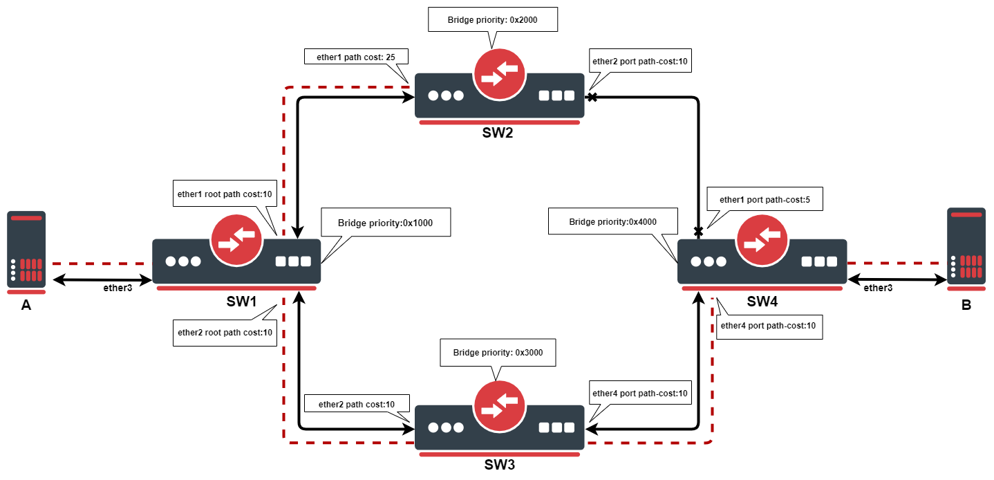
This example outlines how the root path cost works. SW1 will be the root bridge, due to it having the lowest priority of 0x1000, as the root bridge. Each bridge will calculate the path cost to the root bridge. When calculating root path cost bridges take into account configured path cost on their ports + root path cost advertised by neighboring bridges.
SW1: due to it being the root bridge, it advertises root path cost of 0 to its neighbors, even though it has a configured path cost of 10.
SW2: ether1. has root path cost of 0 + 25=25. On the ether2 path cost will be 10+10+10+0=30
SW3: ether2, has root path cost of 0 + 10=10. On the ether4 path cost will be 10+5+25+0=40
SW4: ether1, has root path cost of 0+25+5=30. On ether4 path cost will be 10+10+0=20
Port with the lowest path cost will be elected as the root port. Every bridge in STP topology needs a path to root bridge, after the best path has been found, the redundant path will be blocked, in this case, path between SW2 and SW4.
You can configure path cost on the root bridge, but it will only be taken into account when the bridge loses its root status.
STP example
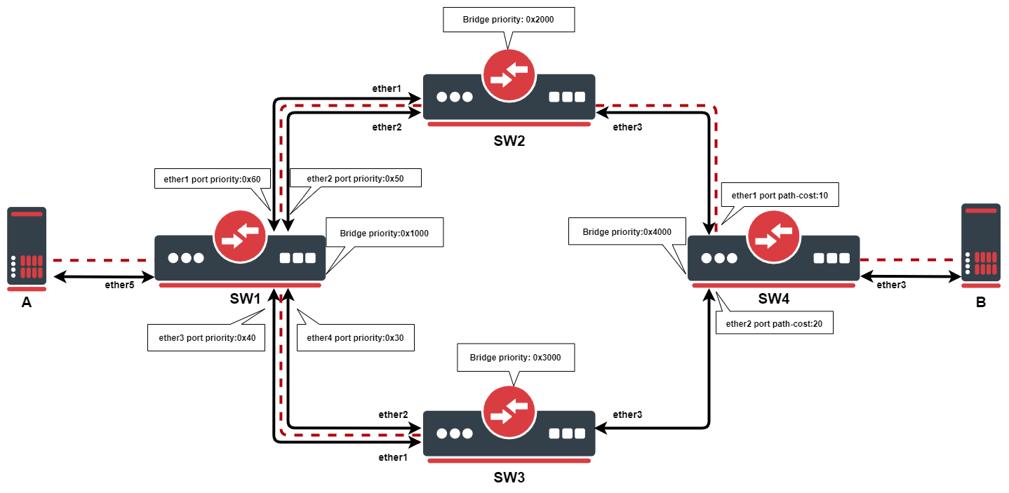
In this example, we want to ensure Layer2 redundancy for connections from ServerA to ServerB. If a port is connected to a device that is not a bridge and not running (R)STP, then this port is considered as an edge port, in this case ServerA and ServerB is connected to an edge port. This is possible by using STP in a network. Below are configuration examples for each switch.
- Configuration for SW1:
/interface bridge
add name=bridge priority=0x1000
/interface bridge port
add bridge=bridge interface=ether1 priority=0x60
add bridge=bridge interface=ether2 priority=0x50
add bridge=bridge interface=ether3 priority=0x40
add bridge=bridge interface=ether4 priority=0x30
add bridge=bridge interface=ether5
- Configuration for SW2:
/interface bridge
add name=bridge priority=0x2000
/interface bridge port
add bridge=bridge interface=ether1
add bridge=bridge interface=ether2
add bridge=bridge interface=ether3
- Configuration for SW3:
/interface bridge
add name=bridge priority=0x3000
/interface bridge port
add bridge=bridge interface=ether1
add bridge=bridge interface=ether2
add bridge=bridge interface=ether3
- Configuration for SW4:
/interface bridge
add name=bridge priority=0x4000
/interface bridge port
add bridge=bridge interface=ether1
add bridge=bridge interface=ether2 path-cost=20
add bridge=bridge interface=ether3
In this example, SW1 is the root bridge since it has the lowest bridge priority. SW2 and SW3 have ether1,ether2 connected to the root bridge and ether3 is connected to SW4. When all switches are working properly, the traffic will be flowing from ServerA through SW1_ether2, through SW2, through SW4 to ServerB. In the case of SW1 failure, the SW2 becomes the root bridge because of the next lowest priority, indicated by the dotted line in the diagram. Below is a list of ports and their role for each switch:
- root-port — SW2_ether2, SW3_ether2, SW4_ether1
- alternate-port — SW2_ether1, SW3_ether1, SW4_ether2
- designated-port — SW1_ether1, SW1_ether2, SW1_ether3, SW1_ether4, SW1_ether5, SW2_ether3, SW2_ether3, SW4_ether3
Note: By the 802.1Q recommendations, you should use bridge priorities in steps of 4096. To set a recommended priority it is more convenient to use hexadecimal notation, for example, 0 is 0x0000, 4096 is 0x1000, 8192 is 0x2000 and so on (0..F).
Multiple Spanning Tree Protocol
Multiple Spanning Tree Protocol (MSTP) is used on a bridge interface to ensure loop-free topology across multiple VLANs, MSTP can also provide Layer2 redundancy and can be used as a load balancing technique for VLANs since it has the ability to have different paths across different VLANs. MSTP is operating very similarly to (R)STP and many concepts from (R)STP can be applied to MSTP and it is highly recommended to understand the principles behind (R)STP before using MSTP, but there are some differences that must be taken into account when designing an MSTP enabled network.
In case (R)STP is used, the BPDUs are sent across all physical interfaces in a bridge to determine loops and stop ports from being able to forward traffic if it causes a loop. In case there is a loop inside a certain VLAN, (R)STP might not be able to detect it. Some STP variants solve this problem by running an STP instance on every single VLAN (PVST), but this has been proven to be inefficient and some STP variants solve this problem by running a single STP instance across all VLANs (CST), but it lacks the possibility to do load balancing for each VLAN or VLAN group. MSTP tends to solve both problems by using MST instances that can define a group of VLANs (VLAN mapping) that can be used for load balancing and redundancy, this means that each VLAN group can have a different root bridge and a different path. Note that it is beneficial to group multiple VLANs in a single instance to reduce the amount of CPU cycles for each network topology change.
In RouterOS with MSTP enabled the bridge priority is the CIST’s root bridge priority, as stated in the IEEE 802.1Q standard the bridge priority must be in steps of 4096, the 12 lowest bits are ignored. These are valid bridge priorities: 0, 4096, 8192, 12288, 16384, 20480, 24576, 28672, 32768, 36864, 40960, 45056, 49152, 53248, 57344, 61440. When setting an invalid bridge priority, RouterOS will warn you about it and trunk the value to a valid value, but will save the original value in the configuration since invalid bridge priority values can still be used in (R)STP between devices running RouterOS, though it is recommended to use valid a bridge priority instead.
MSTP Regions
MSTP works in groups called regions, for each region there will be a regional root bridge and between regions, there will be a root bridge elected. MSTP will use Internal Spanning Tree (IST) to build the network topology inside a region and Common Spanning Tree (CST) outside a region to build the network topology between multiple regions, MSTP combines these two protocols into Common and Internal Spanning Tree (CIST), which holds information about topology inside a region and between regions. From CST’s perspective, a region will seemingly be as a single virtual bridge, because of this MSTP is considered very scalable for large networks. In order for bridges to be in the same region, their configuration must match, BPDUs will not include VLAN mappings since they can be large, rather a computed hash is being transmitted. If a bridge receives a BPDU through a port and the configuration does not match, then MSTP will consider that port as a boundary port and that it can be used to reach other regions. Below is a list of parameters that need to match in order for MSTP to consider a BPDU from the same region:
- Region name
- Region revision
- VLAN mappings to MST Instance IDs (computed hash)
It is possible to create MSTP enabled network without regions, though to be able to do load balancing per VLAN group it is required for a bridge to receive a BPDU from a bridge that is connected to it with the same parameters mentioned above. In RouterOS the default region name is empty and region revision is 0, which are valid values, but you must make sure that they match in order to get multiple bridges in a single MSTP region. A region cannot exist if their bridges are scattered over the network, these bridges must be connected at least in one way, in which they can send and receive BPDUs without leaving the region, for example, if a bridge with different region related parameters is between two bridges that have the same region related parameters, then there will exist at least 3 different MSTP regions.
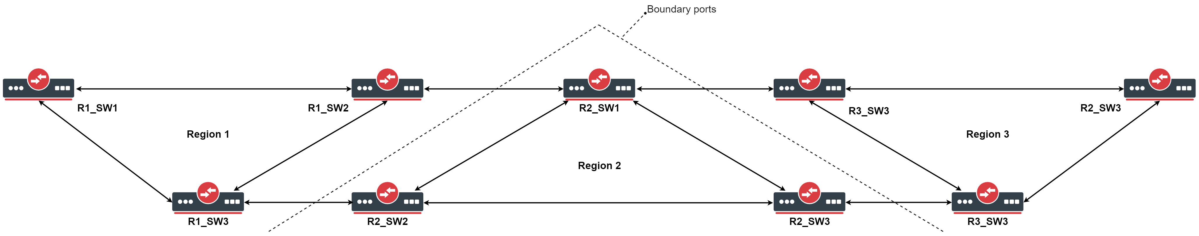
The downside of running every single bridge in a single MSTP region is the excess CPU cycles. In comparison, PVST(+) creates a Spanning Tree Instance for each VLAN ID that exists on the network, since there will be very limited paths that can exist in a network, then this approach creates a lot of overhead and unnecessary CPU cycles, this also means that this approach does not scale very well and can overload switches with not very powerful CPUs. MSTP solves this problem by dividing the network into MSTP regions, where each bridge inside this region will exchange and process information about VLANs that exist inside the same region, but will run a single instance of Spanning Tree Protocol in the background to maintain the network topology between regions. This approach has been proven to be much more effective and much more scalable, this means that regions should be used for larger networks to reduce CPU cycles.
In regions, you can define MST Instances, which are used to configure load balancing per VLAN group and to elect the regional root bridge. It is worth mentioning that in each region there exists a pre-defined MST Instance, in most documentations, this is called as MSTI0· This MST Instance is considered as the default MST Instance, there are certain parameters that apply to this special MST Instance. When traffic is passing through an MSTP enabled bridge, MSTP will look for an MST Instance that has a matching VLAN mapping, but if a VLAN mapping does not exist for a certain VLAN ID, then traffic will fall under MSTI0.
Since MSTP requires VLAN filtering on the bridge interface to be enabled, then make sure that you have allowed all required VLAN IDs in /interface bridge vlan, otherwise, the traffic will not be forwarded and it might seem as MSTP misconfigured, although this is a VLAN filtering misconfiguration.
Election process
The election process in MSTP can be divided into two sections, intra-region and inter-region. For MSTP to work properly there will always need to be a regional root, that is the root bridge inside a region, and a CIST root, that is the root bridge between regions. A regional root is the root bridge inside a region, regional root bridge will be needed to properly set up load balancing for VLAN groups inside a region. CIST root will be used to configure which ports will be alternate/backups ports (inactive) and which ports will be root ports (active).
Between regions, there is no load balancing per VLAN group, root port election process and port blocking between MSTP regions is done the same way as in (R)STP. If CIST has blocked a port that is inside an MSTP region to prevent traffic loops between MSTP regions, then this port can still be active for IST to do load balancing per VLAN group inside an MSTP region.
- The following parameters are involved to elect a regional root bridge or root ports inside a MSTP region:
| Property | Description |
|---|---|
| priority (integer: 0..65535 decimal format or 0x0000-0xffff hex format; Default: 32768 / 0x8000) | /interface bridge msti, MST Instance priority, used to elect a regional root inside a MSTP region. |
| internal-path-cost (integer: 1..4294967295; Default: 10) | /interface bridge port, path cost to the regional root for unknown VLAN IDs (MSTI0), used on a root port inside a MSTP region. |
| priority (integer: 0..240; Default: 128) | /interface bridge port mst-override, MST port priority for a defined MST Instance, used on a bridge port on the regional root bridge. |
| internal-path-cost (integer: 1..200000000; Default: 10) | /interface bridge port mst-override, MST port path cost for a defined MST Instance, used on a non-root bridge port inside a MSTP region. |
- The following parameters are involved to elect a CIST root bridge or CIST root ports:
| Property | Description |
|---|---|
| priority (integer: 0..65535 decimal format or 0x0000-0xffff hex format; Default: 32768 / 0x8000) | /interface bridge, CIST bridge priority, used to elect a CIST root bridge. |
| priority (integer: 0..240; Default: 128) | /interface bridge port, CIST port priority, used on a CIST root bridge to elect CIST root ports. |
| path-cost (integer: 1..4294967295; Default: 10) | /interface bridge port, CIST port path cost, used on a CIST non-root bridge port to elect CIST root ports. |
The sequence of parameters in which MSTP checks to elect root bridge/ports are the same as in (R)STP, you can read more about it at the (R)STP Election Process section.
MST Instance
Sub-menu: /interface bridge msti
This section is used to group multiple VLAN IDs to a single instance to create a different root bridge for each VLAN group inside an MSTP region.
| Property | Description |
|---|---|
| bridge (text; Default: ) | Bridge to which assign an MST instance. |
| identifier (integer: 1..31; Default: ) | MST instance identifier. |
| priority (integer: 0..65535 decimal format or 0x0000-0xffff hex format; Default: 32768 / 0x8000) | MST instance priority, used to determine the root bridge for a group of VLANs in an MSTP region. |
| vlan-mapping (integer: 1..4094; Default: ) | The list of VLAN IDs to assign to MST instance. This setting accepts the VLAN ID range, as well as comma, separated values. E.g. vlan-mapping=100-115,120,122,128-130 |
MST Override
Sub-menu: /interface bridge port mst-override
This section is used to select the desired path for each VLAN mapping inside an MSTP region.
| Property | Description |
|---|---|
| disabled (yes | no; Default: no) | Whether entry is disabled. |
| internal-path-cost (integer: 1..200000000; Default: 10) | Path cost for an MST instance’s VLAN mapping, used on VLANs that are facing towards the root bridge to manipulate path selection, lower path cost is preferred. |
| identifier (integer: 1..31; Default: ) | MST instance identifier. |
| priority (integer: 0..240; Default: 128) | The priority an MST instance’s VLAN, used on VLANs that are facing away from the root bridge to manipulate path selection, lower priority is preferred. |
| interface (name; Default: ) | Name of the port on which use configured MST instance’s VLAN mappings and defined path cost and priority. |
Monitoring
Similarly to (R)STP, it is also possible to monitor MSTP status. By monitoring the bridge interface itself it possible to see the current CIST root bridge and the current regional root bridge for MSTI0, it is also possible to see the computed hash of MST Instance identifiers and VLAN mappings, this is useful when making sure that certain bridges are in the same MSTP region. Below you can find an example to monitoring an MSTP bridge:
/interface bridge monitor bridge
                    state: enabled
      current-mac-address: 6C:3B:6B:7B:F0:AA
              root-bridge: no
           root-bridge-id: 0x1000.64:D1:54:24:23:72
  regional-root-bridge-id: 0x4000.6C:3B:6B:7B:F0:AA
           root-path-cost: 10
                root-port: ether4
               port-count: 5
    designated-port-count: 3
        mst-config-digest: 74edbeefdbf82cf63a70cf60e43a56f3
In MSTP it is possible to monitor the MST Instance, this is useful to determine the current regional root bridge for a certain MST Instance and VLAN group, below you can find an example to monitor an MST Instance:
/interface bridge msti monitor 1
                    state: enabled
               identifier: 2
      current-mac-address: 6C:3B:6B:7B:F0:AA
              root-bridge: no
           root-bridge-id: 0.00:00:00:00:00:00
  regional-root-bridge-id: 0x1002.6C:3B:6B:7B:F9:08
           root-path-cost: 0
                root-port: ether2
               port-count: 5
    designated-port-count: 1
It is also possible to monitor a certain MST Override entry, this is useful to determine the port role for a certain MST Instance when configuring root ports and alternate/backup ports in an MSTP region, below you can find an example to monitor an MST Override entry:
/interface bridge port mst-override monitor 1
                      port: ether3
                    status: active
                identifier: 2
                      role: alternate-port
                  learning: no
                forwarding: no
   internal-root-path-cost: 15
         designated-bridge: 0x1002.6C:3B:6B:7B:F9:08
  designated-internal-cost: 0
    designated-port-number: 130
MSTP example
Let’s say that we need to design topology and configure MSTP in a way that VLAN 10,20 will be forwarded in one path, but VLAN 30,40 will be forwarded in a different path, while all other VLAN IDs will be forwarded in one of those paths. This can easily be done by setting up MST Instances and assigning port path costs, below you can find a network topology that needs to do load balancing per VLAN group with 3 separate regions as an example:
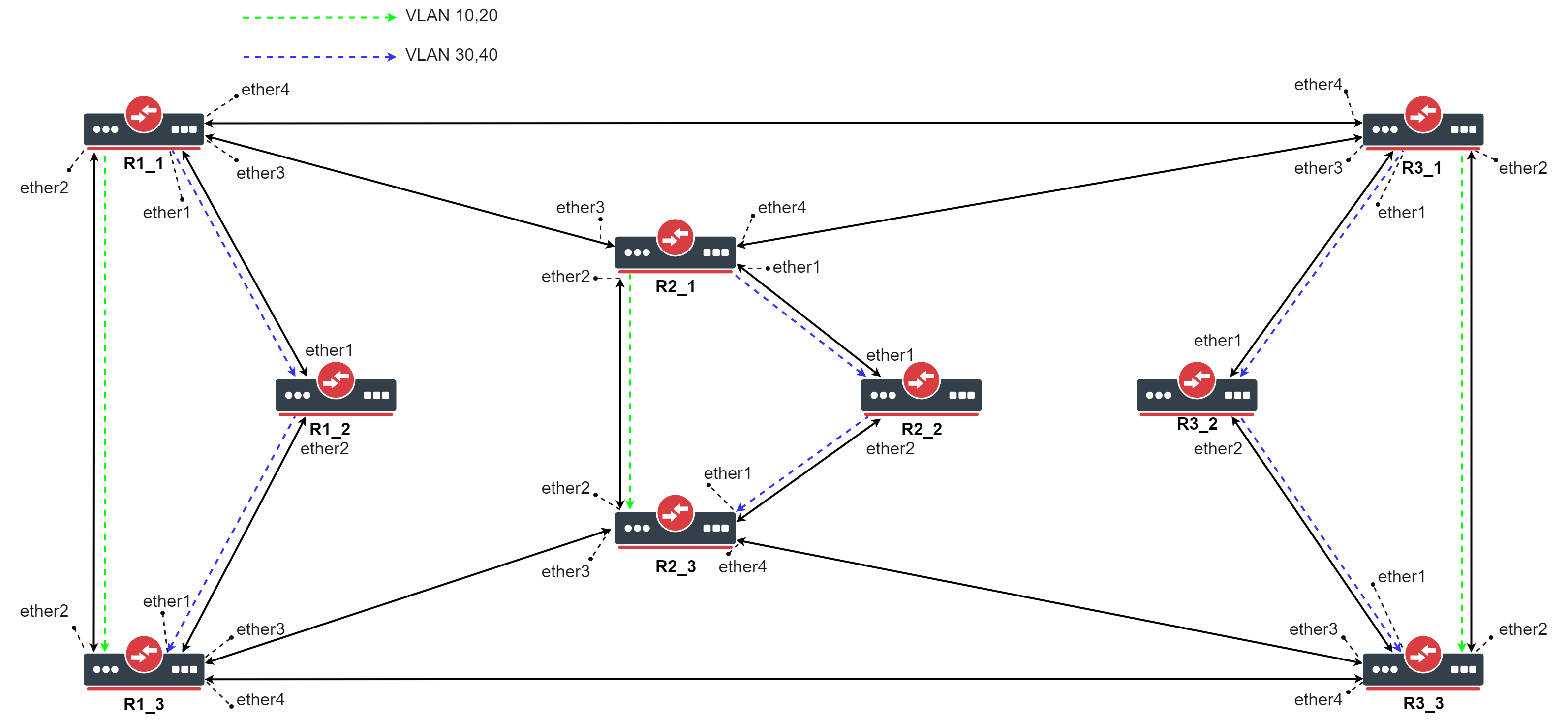 The topology of an MSTP enabled network with load balancing per VLAN group
Start by adding each interface to a bridge, initially, you should create a (R)STP bridge without VLAN filtering enabled, this is to prevent losing access to the CPU. Each device in this example is named by the region that it is in (Rx) and a device number (_x). For larger networks configuring MSTP can be confusing because of the number of links and devices, we recommend using The Dude to monitor and design a network topology.
- Use the following commands on R1_1, R1_3, R2_1, R2_3, R3_1, R3_3:
/interface bridge
add name=bridge protocol-mode=rstp vlan-filtering=no
/interface bridge port
add bridge=bridge interface=ether1
add bridge=bridge interface=ether2
add bridge=bridge interface=ether3
add bridge=bridge interface=ether4
- Use the following commands on R1_2, R2_2, R3_2:
/interface bridge
add name=bridge protocol-mode=rstp vlan-filtering=no
/interface bridge port
add bridge=bridge interface=ether1
add bridge=bridge interface=ether2
- Make sure you allow the required VLAN IDs on these devices, here we will consider that each device will receive tagged traffic that needs to be load balanced per VLAN group, use these commands on R1_1, R1_3, R2_1, R2_3, R3_1, R3_3:
/interface bridge vlan
add bridge=bridge tagged=ether1,ether2,ether3,ether4 vlan-ids=10,20,30,40
- Use the following commands on R1_2, R2_2, R3_2:
/interface bridge vlan
add bridge=bridge tagged=ether1,ether2 vlan-ids=10,20,30,40
Make sure you add all the needed VLAN IDs and ports to the bridge VLAN table, otherwise your device will not forward all required VLANs and/or you will lose access to the device.
We need to assign a region name for each bridge that we want to be in a single MSTP region, you can also specify the region revision, but it is optional, though they need to match. In this example, if all bridges will have the same region name, then they will all be in a single MSTP bridge. In this case, we want to separate a group of 3 bridges in a different MSTP region to do load balancing per VLAN group and to create diversity and scalability.
- Set appropriate region name (and region revision) for each bridge, use the following commands on each device (change the region name!):
/interface bridge
set bridge region-name=Rx region-revision=1
After we have created 3 different MSTP regions, we need to decide which device is going to be a regional root for each VLAN group. For consistency, we are going to set the first device (_1) in each region as the regional root for VLAN 10,20 and the third device (_3) in each region as the regional root for VLAN 30,40. This can be done by creating an MST Instance for each VLAN group and assigning a bridge priority to it. The MST Instance identifier is only relevant inside an MSTP region, outside an MSTP region these identifiers can be different and mapped to a different VLAN group.
- Use the following commands on R1_1, R2_1, R3_1:
/interface bridge msti
add bridge=bridge identifier=1 priority=0x1000 vlan-mapping=10,20
add bridge=bridge identifier=2 priority=0x3000 vlan-mapping=30,40
- Use the following commands on R1_3, R2_3, R3_3:
/interface bridge msti
add bridge=bridge identifier=1 priority=0x3000 vlan-mapping=10,20
add bridge=bridge identifier=2 priority=0x1000 vlan-mapping=30,40
- Use the following commands on R1_2, R2_2, R3_2:
/interface bridge msti
add bridge=bridge identifier=1 priority=0x2000 vlan-mapping=10,20
add bridge=bridge identifier=2 priority=0x2000 vlan-mapping=30,40
Now we need to override the port path-cost and/or port priority for each MST Instance. This can be done by adding a MST-Override entry for each port and each MST Instance. To achieve that for a certain MST Instance the traffic flow path is different, we simply need to make sure that the port path cost and/or priority is larger. We can either increase the port path cost or either decrease the port path cost to ports that are facing towards the regional root bridge. It doesn’t matter if you increase or decrease all values, it is important that at the end one port’s path cost is larger than the other’s.
- Use the following commands on R1_1, R2_1, R3_1:
/interface bridge port mst-override
add identifier=2 interface=ether1 internal-path-cost=5
add identifier=2 interface=ether2 internal-path-cost=15
- Use the following commands on R1_2, R2_2, R3_2:
/interface bridge port mst-override
add identifier=1 interface=ether1 internal-path-cost=5
add identifier=2 interface=ether2 internal-path-cost=9
- Use the following commands on R1_3, R2_3, R3_3:
/interface bridge port mst-override
add identifier=1 interface=ether2 internal-path-cost=5
add identifier=1 interface=ether3 internal-path-cost=9
In this case for VLAN 10,20 to reach the third device from the first device, it would choose between ether1 and ether2, one port will be blocked and set as an alternate port, ether1 will have path cost as 5+9=14 and ether2 will have path cost as 10, ether2 will be elected as the root port for MSTI1 on the third device. In case for VLAN 30,40 to reach the first device from the third device, ether1 will have path cost as 5+9=14 and ether2 will have path cost as 15, ether1 will be elected as the root port for MSTI2 on the third device.
Now we can configure the root ports for MSTI0, in which will fall under all VLANs that are not assigned to a specific MST Instance, like in our example VLAN 10,20 and VLAN 30,40. To configure this special MST Instance, you will need to specify internal-path-cost to a bridge port. This value is only relevant to MSTP regions, it does not have any effect outside an MSTP region. In this example will choose that all unknown VLANs will be forwarded over the same path as VLAN 30,40, we will simply increase the path cost on one of the ports.
- Use the following commands on R1_3, R2_3, R3_3:
/interface bridge port
set [find where interface=ether3] internal-path-cost=25
At this point, a single region MSTP can be considered as configured and in general, MSTP is fully functional. It is highly recommended to configure the CIST part, but for testing purposes, it can be left with the default values. Before doing any tests, you need to enable MSTP on all bridges.
- Use the following commands on all devices:
/interface bridge
set bridge protocol-mode=mstp vlan-filtering=yes
When MSTP regions have been configured, you can check if they are properly configured by forwarding traffic, for example, send tagged traffic from the first device to the third device and change the VLAN ID for the tagged traffic to observe different paths based on VLAN ID. When this is working as expected, then you can continue to configure CIST related parameters to elect a CIST root bridge and CIST root ports. For consistency we will choose the first device in the first region to be the CIST root bridge and to ensure the consistency in case of failure we can set a higher priority to all other bridges.
- Use the following commands on R1_1:
/interface bridge
set bridge priority=0x1000
- Use the following commands on R1_2:
/interface bridge
set bridge priority=0x2000
- …
- Use the following commands on R3_3:
/interface bridge
set bridge priority=0x9000
We also need to elect a root port on each bridge, for simplicity we will choose the port that is closest to Ŗ1_1 as the root port and has the least hops. At this point the procedure to elect root ports is the same as the procedure in (R)STP.
- Use the following commands on R3_3:
/interface bridge port
set [find where interface=ether2] path-cost=30
set [find where interface=ether3] path-cost=40
set [find where interface=ether4] path-cost=20
-
Use the following commands on R1_3 and R2_3:
/interface bridge port
set [find where interface=ether2] path-cost=20
set [find where interface=ether3] path-cost=30
- Use the following commands on R1_2:
/interface bridge port
set [find where interface=ether1] path-cost=30
Добрый день дорогие читатели! Сегодня мы с вами поговорим о протоколе, который функционирует на большинстве серьезных коммутаторов, но о важной и неприметной работе которого знают далеко не все, а именно о протоколе STP (Spanning Tree Protocol, Протокол связующего дерева). В данной статье мы поговорим о его назначение, а в следующих статьях мы поговорим о его настройке и принципах его функционирования.
Как всегда, рассматривать работу протокола STP мы будем на конкретном примере, а именно на примере топологии сети представленной на рисунке ниже:
 |
| Топология содержащая резервные каналы |
И так, пусть у нас есть сеть содержащая резервные пути распространения фреймов (закольцованная сеть), и пусть один из компьютеров сети, например PC0, посылает в данную сеть широковещательный фрейм. Что же произойдет в данном случае? Данный фрейм будет передан на коммутатор Switch0, который в свою очередь передаст полученный фрейм через все свои активные порты, кроме того через который он поступил на коммутатор (а именно через Gig0/1 и Gig0/2). Фрейм поступит на коммутаторы Switch1 и Switch3, они поступят аналогичным образом и передадут фрейм через порты Fast0/1, Gig0/1 и Fast0/1, Gig0/2. Судьба фреймов поступивших на хосты нас не интересует, а вот о фреймах поступивших на коммутатор Switch2 поговорим далее. На коммутатор Switch2 поступает сразу две копии одного фрейма, одна через интерфейс Gig0/1, другая через интерфейс Gig0/2. Копия поступившая через интерфейс Gig0/1, будет передана через интерфейсы Gig0/2 и Fast0/1. А копия поступившая через интерфейс Gig0/2 будет передана через интерфейсы Gig0/1 и Fast0/1. Судьба фреймов отправленных на хосты нас опять же не интересует. А вот фреймы отправленные далее на коммутаторы, как вы уже наверное понимаете поступают на коммутаторы Switch1 и Switch3, обрабатываются стандартным образом, и как вы уже наверное догадались возвращаются обратно на коммутатор Switch0, но уже не через интерфейс Fast0/1, как это было в начале, а через интерфейсы Gig0/1 и Gig0/2. Как легко догадаться коммутатор Switch0 обработает эту пару фреймов, точно так же как это делал коммутатор Switch2, когда на него поступало две копии фреймов, и фреймы будут отправлены далее по кольцу. Данная циркуляция фреймов по замкнутому контуру будет продолжаться бесконечно до тех пор пока не откажет один из коммутаторов, их портов или каналов между ними (Это происходит из за того, что у фрейма, в отличие от IP пакета, в заголовке отсутствует поле TTL, отвечающее за время его жизни. Если бы у нас циркулировал IP пакет по кольцевому маршруту составленному из маршрутизаторов, то рано или поздно он бы был отброшен, так как его поле TTL исчерпало бы себя).
 |
| Циркуляция фреймов в топологии имеющей резервные каналы |
Данное явление бесконечной циркуляции фреймов по замкнутым кольцевым топологиям порождает сразу несколько проблем. Во первых в сети многократно передаются совершенно никому не нужные фреймы, которые занимают полезную пропускную способность сети, причем если коммутаторы и связывающие их каналы функционируют исправно, то эти фреймы никуда не деваются и их количество только растет со временем. Во вторых из за данной циркуляции фреймов, возникают ошибки в построении таблицы коммутации коммутаторов. Как вы наверное помните коммутаторы просматривают заголовки входящих фреймов и анализируют поле содержащее адрес их отправителя. Если MAC адрес, указанный в заголовке, отсутствует в таблице коммутации коммутатора то он добавляется в нее и устанавливается соответствие между портом коммутатора и MAC адресом. Если же фрейм с аналогичным MAC адресом приходит с другого порта коммутатора, то запись в таблице коммутатора обновляется и составляется новое соответствие между MAC адресом и портом коммутатора. Разберем это на примере. Пусть хост PC0 имеет MAC адрес MAC0. Когда широковещательный фрейм от данного хоста поступает на коммутатор Switch0, то он создает в своей таблице коммутации запись вида MAC0 — Fast0/1. Но как мы уже разбирали ранее коммутатор Switch0 передает поступивший на него широковещательный фрейм в кольцо, и через какое то время данный фрейм поступит на него обратно, но уже через интерфейс Gig0/1 и Gig0/2. Будем считать что фрейм сначала вернулся через интерфейс Gig0/1. В заголовке фрейма все еще содержится MAC адрес хоста PC0. Коммутатор видит знакомый ему MAC адрес в заголовке, но он так же видит что данный фрейм пришел не из порта Fast0/1, а из порта Gig0/1, поэтому коммутатор обновляет запись в таблице коммутации с MAC0 — Fast0/1 на MAC0 — Gig0/1. Что как вы понимаете является не верным. Если в данный момент на коммутатор Switch0 поступит фрейм предназначенный для хоста PC0, то он ошибочно будет передан не через интерфейс Fast0/1, а через интерфейс Gig0/1, что как уже можно догадаться приведет к проблемам коммутации.
Для устранения зацикливания фреймов в сетевых топологиях имеющих резервные маршруты был разработан протокол STP(Spanning Tree Protocol, Протокол связующего дерева). Который функционирует довольно просто — он блокирует передачу фреймов на одном из активных интерфейсов входящих в кольцо коммутаторов, тем самым разрывая кольцо и превращая его в древовидную топологию, для которой проблемы связанные с бесконечной циркуляцией фреймов не свойственны.
Если вы соединяли несколько коммутаторов в Packet Tracer и образовывали при этом кольцо, то вы наверное видели что один из портов на одном из коммутаторов так и не окрашивался в зеленый цвет, и так и оставался оранжевым. Поздравляю — вы наблюдали работу протокола STP! А тот порт который остался оранжевым и есть тот отключенный порт.
Стоит отметить что протокол STP блокирует определенный порт коммутатора не на все время существования сети, а только до изменений в ее топологии. Например если в топологии представленной на рисунках данной статьи оборвать канал между коммутаторами Switch0 и Switch3, то произойдет повторная работа протокола STP для вновь образовавшейся топологии и порт Gig0/2 коммутатор Switch1 включится через некоторое время, для восстановления связности сети.
Так же стоит отметить что во время своей работы протокол STP не отключает порт, а именно блокирует его. В этом можно убедиться выполнив на коммутаторе, имеющем заблокированный порт, команду show ip interface brief. В графах Status и Protocol будет UP, что говорит о том, что порт включен и исправно функционирует. А вот если мы выполним команду show spanning-tree interface <название интерфейса> то в графе Sts можно будет увидеть состояние порта в протоколе STP. Если порт не заблокирован состояние будет — FWD, а если заблокирован BLK. Так же для получения аналогичной информации о всех интерфейсах коммутатора можно выполнить команду show spanning-tree active.
На сегодня это все, о конфигурации протокола STP и его принципе действия поговорим в следующих статьях.