STM32CubeIDE is an Integrated Development Environment (IDE) that provides a comprehensive and user-friendly platform for developing and debugging STM32 microcontroller applications. It provides a range of tools for code development, debugging, and testing, making it an ideal solution for embedded systems developers. If you’re new to STM32CubeIDE, you may be wondering how to get started with downloading and installing this software. In this article, we’ll provide a step-by-step guide to help you get started with STM32CubeIDE, including how to download and install the software on your computer. Whether you’re a beginner or an experienced developer, this guide will help you get started with STM32CubeIDE and start developing your next project.
Downloading STM32CubeIDE
In this section, we will first show you how to set up download STM32CubeIDE for Windows, Linux, and macOS.
Go to the following link:

Click the ‘Get latest’ block according to your operating system. We are using Windows.

The following form will open up. You will have to register your account. Give the following information and click the ‘Download’ button. If you already have an account on my.st.com then you can use that to login as well.
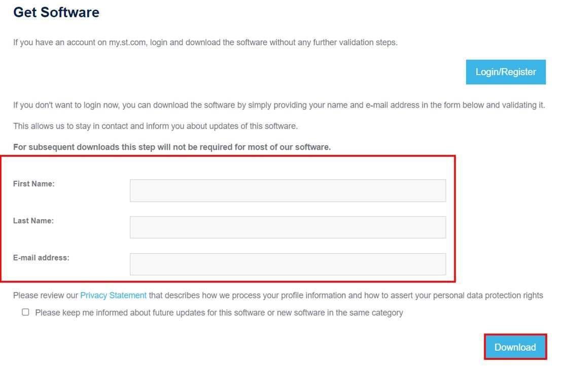
After specifying your personal information and clicking the download button your registration will be complete. You will be given a link in your email address to validate your email address after which the download will automatically start. Note that this email address is the one which you used for registration. The email will be sent by STMicroelectronics.
Installing STM32CubeIDE
A few moments later, after specifying the directory your download will start. After opening the .zip file you will be asked for your agreement. After accepting the agreement and choosing the desired location to install the IDE, the installation process will start. It will take some time for STM32CubeIDE to get installed.
After the installation is complete, click ‘Next’.
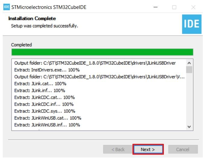
After the installation is completed, click ‘Finish’ to close the setup. Your desktop will now have a shortcut to STM32CubeIDE created.

In this section, we will see how to get started with STM32CubeIDE by creating our first project, For demonstration purposes, we will learn to use GPIO pins of STM32 Blue Pill as digital output pins and see how to configure GPIO pins as digital output in STM32CubeIDE.
For demonstration purposes, we will create a LED blinking example using STM32 Blue Pill. This board has an onboard LED connected to GPIO pin 13.
First, let’s see how to write your first program for STM32 Blue Pill in STM32CubeIDE.
Write your first STM32 Program in STM32CubeIDE
Now that we have already installed the STM32CubeIDE application in our system, let us learn how to use it to program our STM32 boards.
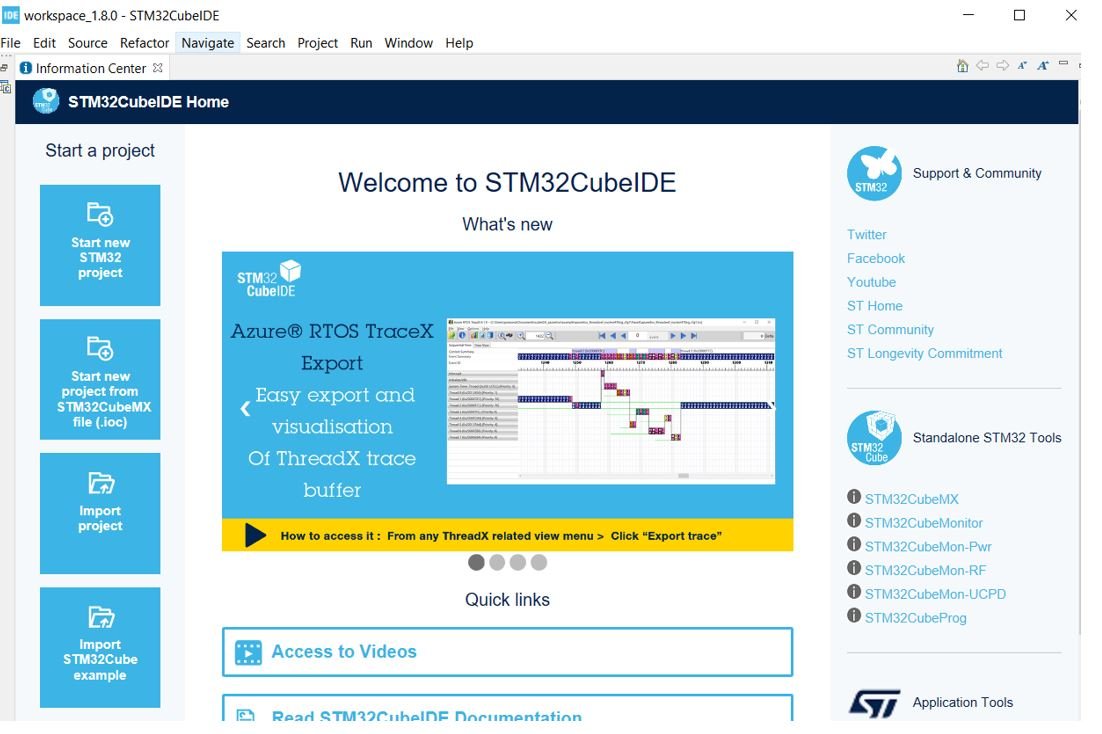
Open the application. You will be asked to specify the directory for the workplace. You can specify the directory and also tick the box below to keep this as the default directory. Next, click ‘Launch’ to start the application.

The STM32CubeIDE workspace will open.
Creating Project in STM32CubeIDE
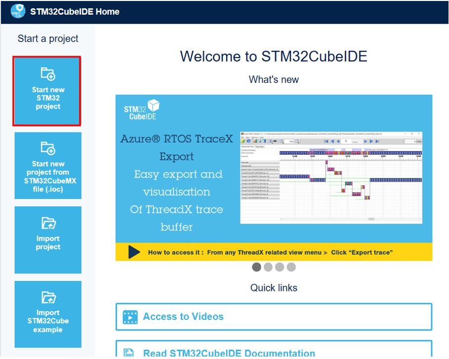
Now click ‘Start new STM32 project’.
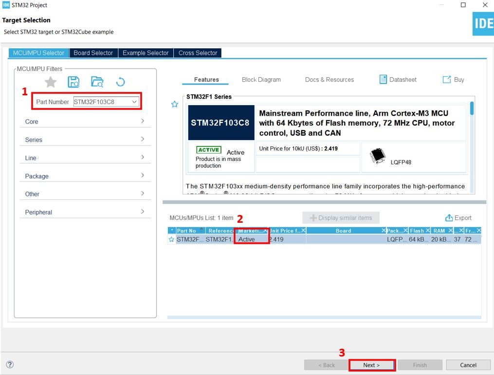
The Target Selection will open.

Select your device from the ‘Part Number.’ We are working with ‘STM32F103C8’.Then click any column entry and then click the ‘Next’ button to proceed further.
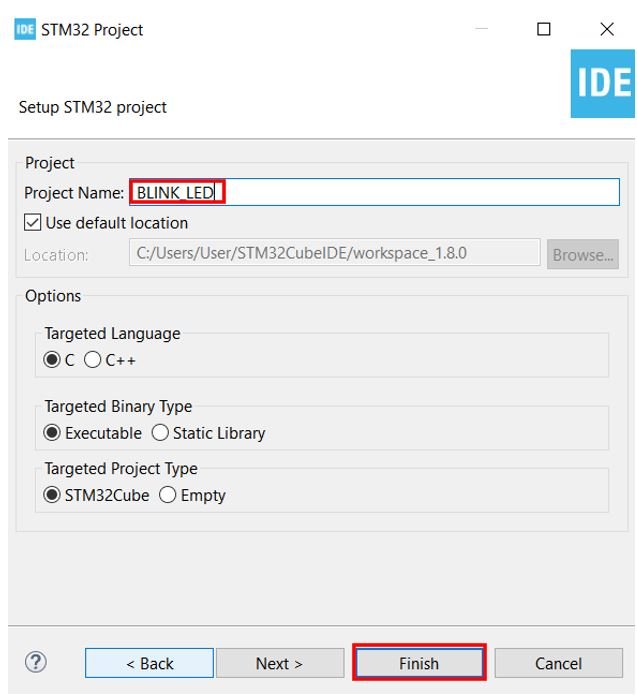
Give your project a name. As we are going to blink the on-board LED of our STM32 board hence we have named our project as ‘BLINK_LED.’ Then click ‘Finish.’
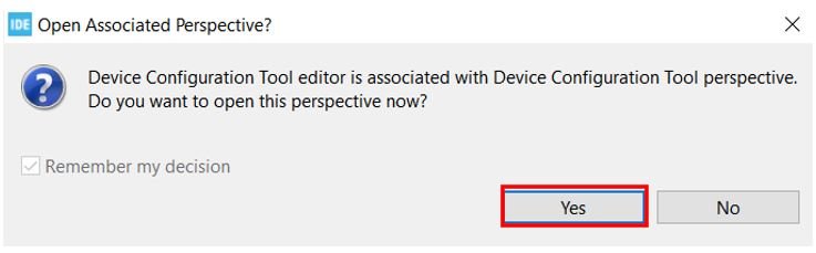
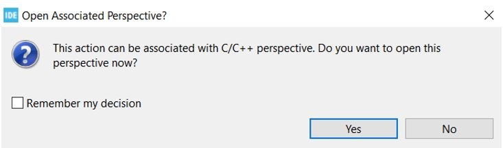
You will be asked to open associated perspective. Click ‘Yes’.
Device Configuration Tool
Now the Device Configuration Tool window will open up. We will be able to set pin specific functions here.
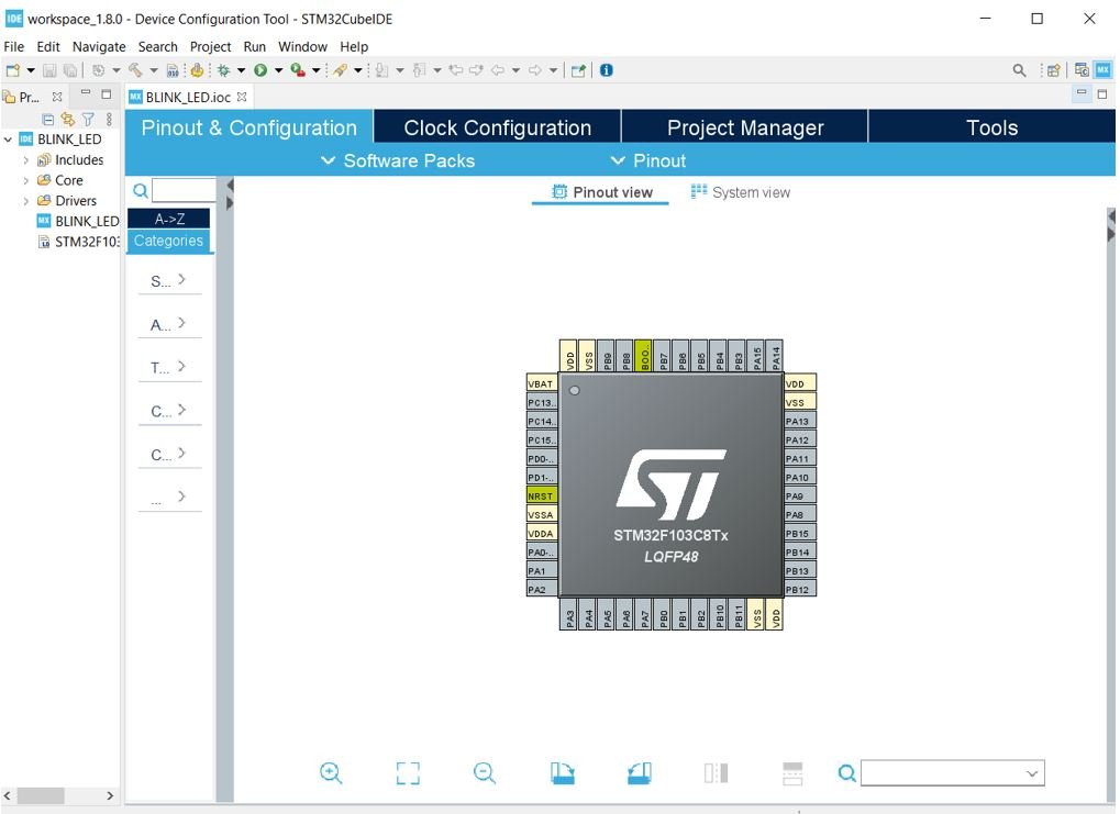
STM32 has an on-board LED connected at PC-13. Refer to the detailed pin out of the board above. Click on PC-13 pin on the Device configuration Tool.

A list of functions will appear associated with the pin. We will set this pin as a ‘GPIO Output.’
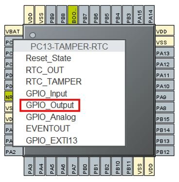
This is how it will look. Here you can see that we have attached GPIO_Output to PC-13.
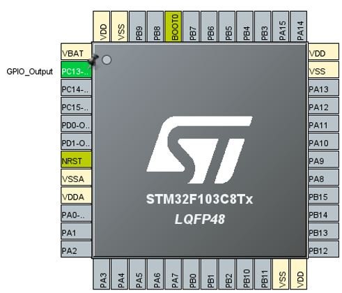
Additionally, we have more options for pins as well. Go to System Core > GPIO > PC-13 and the pin configuration for PC-13 will open up. Here we have given the pin a user label of ‘LED.’ You can see in Device Configuration Tool, that now PC-13 has been given the label ‘LED.’
Apart from the label, there are several other options to choose from including GPIO output level, mode, pull-up/pull-down state, etc.

Now we will save our file. Press Ctrl + S. The following window will appear. Click ‘Yes.’ This will generate a template code for you.

Another window will appear that will ask if you want to open the perspective. Click ‘Yes.’
Code
Now the following page opens. On the right side, you will be able to view the Outline of the code. This happened because we opened our code with perspective.
In the center, you can view the main.c file and on the left you can view the Project Explorer.
If you want to go to the Device Configuration Tool, then click the BLINK_LED.ioc tab.

STM32 Blue Pill LED Blinking Code
Now let us modify the main.c file for our BLINK_LED project. Our aim is to blink the on-board LED indefinitely after a delay.
First, inside the main() function go to while(1) and insert the following lines of code. These will be responsible to blink the onboard LED infinitely.
  while (1)
  {
    HAL_GPIO_WritePin(LED_GPIO_Port, LED_Pin, GPIO_PIN_RESET);
    delay(500000);
    HAL_GPIO_WritePin(LED_GPIO_Port, LED_Pin, GPIO_PIN_SET);
    delay(500000);
  }
Now what is happening is that the HAL_GPIO_WritePin() function takes in three parameters: the onboard LED port, the onboard LED pin, and the state of the pin. This function will be responsible for setting the onboard LED pin either HIGH or LOW.
Notice that we had labelled the onboard LED as ‘LED’ hence we have specified LABEL_GPIO_Port and LABEL_Pin : the first two parameters as LED_GPIO_Port and LED_Port. Remember to replace ‘LABEL’ with your own pin label.
The case where we are specifying the third parameter as GPIO_PIN_RESET, it sets the onboard LED pin to LOW whereas when we are specifying the third parameter as GPIO_PIN_SET, it sets the onboard LED pin to HIGH.
In between these two functions, we are calling the delay() function. It is not an in-built function therefore we will have to define it as well. Insert the following definition of the delay() function after Error_Handler().
void delay (int x)
{
  volatile int i,j;
  for (i=0 ; i < x ; i++)
  {
     j++;
  }
  return;
}
Additionally, add the prototype of the delay() function with the rest of the private function prototypes as shown below:
/* Private function prototypes -----------------------------------------------*/
void SystemClock_Config(void);
static void MX_GPIO_Init(void);
void delay (int x);
Save the main.c file after modifying it. Now we are ready to build our project.
Building Project STM32CubeIDE
To build our BLINK_LED project press Ctrl + B or go to Project > Build All.

Your project will start building. After a few moments, your project will be built if there are no errors.

Connecting ST-Link Programmer with STM32
Now as we have successfully built our BLINK_LED project let us move ahead and upload the code to our STM32 board. To do that, first we will have to connect our Blue Pill STM32 with a ST-Link programmer. We will be using ST-Link V2.

This will provide an interface between our computer and our STM32 board. It consists of 10 pins. We will be using pin2 SWDIO, pin6 SWCLK, pin4 GND, and pin8 3.3V to connect with our STM32 board. The SWDIO is the data input/output pin and the SWCLK is the clock pin. Follow the pin configuration given on the ST-LINK V2 to identify each pin.
Follow the table below to connect both devices correctly.
| STM32 Blue Pill | ST-LINK V2 |
|---|---|
| VCC 3.3V pin | pin8 3.3V |
| SWDIO pin | pin2 SWDIO |
| SWCLK pin | pin6 SWCLK |
| GND pin | pin4 GND |

Additionally move the BOOT jumper to the right to enable the microcontroller to go into programming mode.

Now connect your ST-LINK V2 with your computer via the USB port. Both the devices will power ON.

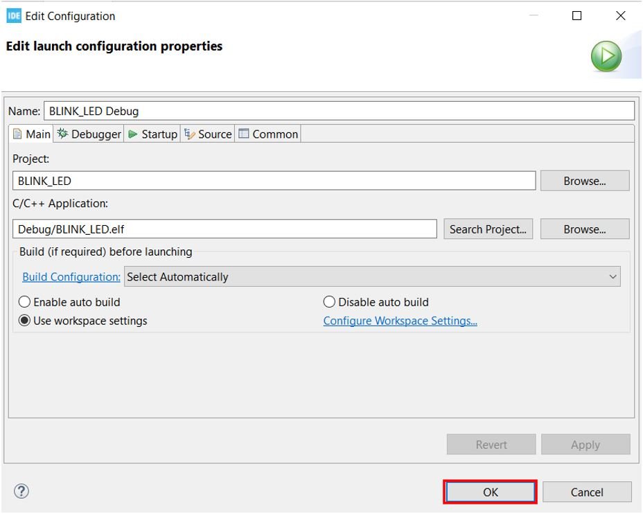
Next press the RUN button in the IDE. The following ‘Edit configuration’ window will open up. Click ‘OK’.
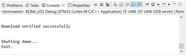
After a few moments, the code will be successfully sent to the STM32 board. You can view it in the Console terminal.
Otherwise, press the RESET button on your STM32 board.
Now to bring the Blue pill back to normal mode make sure you bring the BOOT jumper back at its place. After doing that press the RESET button on the board. Immediately, the onboard LED will start blinking.
Downloading STM32CubeIDE
In this article, we’ll delve into the process of installing an Integrated Development Environment (IDE) for streamlined coding and development. An IDE bundles all the essential tools required for code development, compilation, linking, and debugging. We will focus on the Eclipse-based STM32CubeIDE, tailored for STM32 ARM-based microcontrollers, developed by ST Microelectronics.
Installing an Integrated Development Environment(IDE)
- IDE is a software that contains all the essential tools to develop, compile, link, and debug your code.
- In some cases, you may have to integrate compiler and debugger tools to the IDE manually.
- Throughout this course we will be using Eclipse-based STM32CubeIDE which is developed by ST Microelectronics to write, compile, debug applications on STM32 ARM-based microcontrollers.
- STM32CubeIDE is an eclipse IDE with STM32 related customization.
How to download STM32CubeIDE?
Step 1: Access the Official Link
- Begin by searching for “STM32CubeIDE” and navigate to the official STM32CubeIDE link, as depicted in Figure 1.
Step 2: Logging In or Registration
- At this point, you’ll need to either Login or register an account to download the STM32CubeIDE software. Or you can do one thing, click on Get Software.
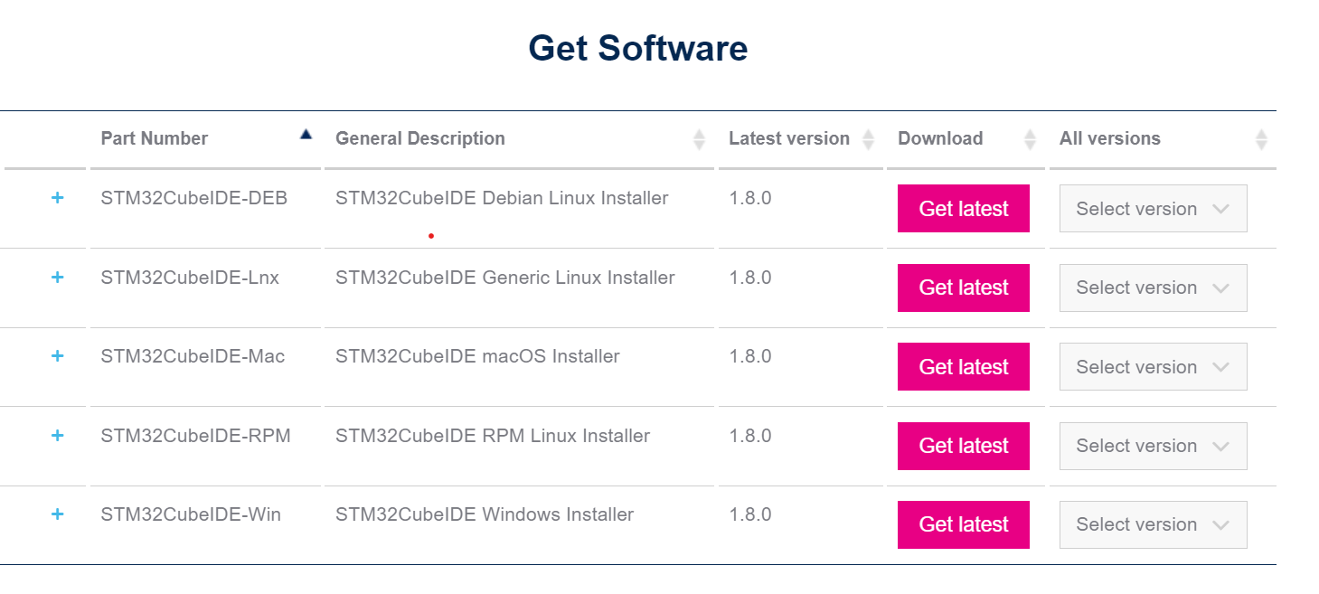
Step 3: Select Software Version
- Choose the appropriate software version based on your operating system. For instance, if you’re on Windows, select “STM32CubeIDE-Win.” The latest version is 1.8.0. Click on “Get Latest.”
Step 4: Accept the License Agreement
- Review and accept the license agreement to proceed.
Step 5: Providing Contact Information
- Here, you’ll need to either Login or register, or provide your email address. ST will send you a download link via email.
- Enter your email and click “Download.”
Step 6: Check Your Email
- Check your inbox for an email from ST.
- This email will contain the subject “Start your software download.” Click on the “Download now” link within the email.
Step 7: Initiating Software Download
- Once you’ve clicked the “Download now” link, you’ll be redirected to the download page.
- Click on “Get Software” to commence the download(Shown in Figure 8).
Step 8: Download Process
- As you can see in Figure 9, the download has started.
The download process is now underway. You’re well on your way to acquiring the STM32CubeIDE software. Follow these steps meticulously to ensure a seamless and successful installation of this powerful IDE.
FastBit Embedded Brain Academy Courses,
Click here: https://fastbitlab.com/course1
FastBitLab
The FastBit Embedded Brain Academy uses the power of internet to bring the online courses related to the field of embedded system programming, Real time operating system, Embedded Linux systems, etc at your finger tip with very low cost. Backed with strong experience of industry, we have produced lots of courses with the customer enrolment over 3000+ across 100+ countries.
In this post, we will be introducing the official development tools offered by ST Micro. It is called STM32CubeIDE and is based on Eclipse and the GNU/GCC toolchain. Eclipse is a very popular integrated development environment (IDE) among embedded developers.
STM32CubeIDE is pretty stable and supports multiple platforms (Windows, Mac and Linux). We will be walking through the setup of the Windows version (1.8.0).
Hardware Platform
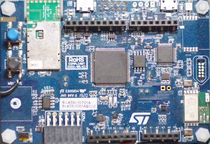
In this post, we will be using an STM32L475 IoT Discovery board (B-L475E-IOT01A) as an example. You may check out more details at its product website B-L475E-IOT01A.
If you need more Flash memory, SRAM and higher CPU speed, you may consider the newer STM32L4S5 IoT Discovery board (B-L4S5I-IOT01A), which comes with a generous 2MB Flash and 640KB SRAM (compared to 1MB Flash and 128KB SRAM of the STM32L475 variation).
Installation
- Download the installer from STM32 website: STM32CubeIDE – Integrated Development Environment for STM32 – STMicroelectronics.
Select version 1.8.0 for Windows.
- Review the license agreement. After accepting it, you will be asked to login to your STM32 account to start the download. Create an account if you have not done so already.
- Download should automatically start. If not, click the Download button again.
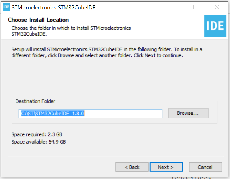
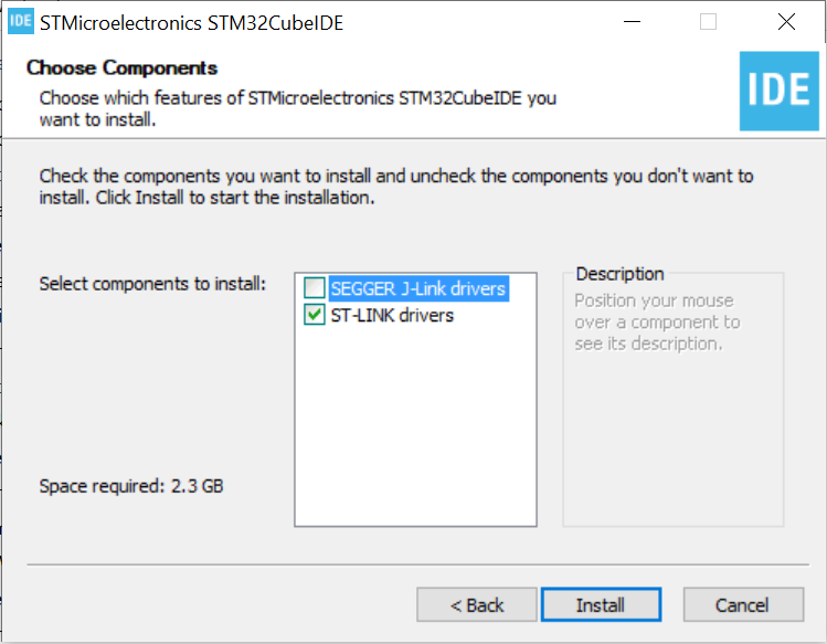
- Unzip the downloaded file and run the installation .exe program. Follow the on-screen instruction to complete the installation. It is suggested that you keep the default installation directory (C:\ST\STM32CubeIDE_1.8.0) as we may refer to it later on. Ensure the option for “ST-LINK drivers” is checked.
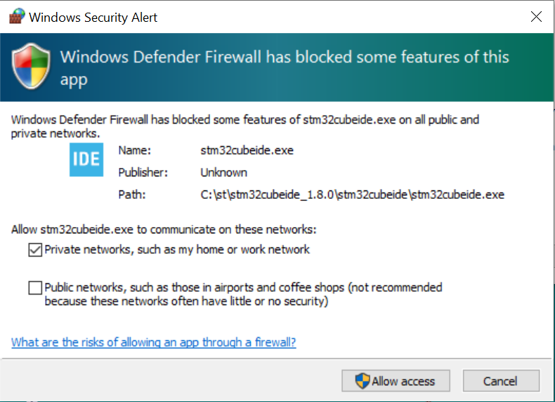
- The installed application is named STM32CubeIDE 1.8.0. On first run, your Windows firewall may prompt you to allow network access. The application requires a network port to communicate with the debugger (OpenOCD or ST-LINK GDB Server). The following screenshot shows enabling the option to allow private network access.
Workspace
- In Eclipse, a workspace is your working environment containing one or more projects. This allows you to configure global settings shared among multiple projects. You may also quickly change your environment by switching to a different workspace. Every time when Eclipse is launched, you will be asked to select your workspace directory. By default it is set to C:\Users\<username>\STM32CubeIDE\workspace_1.8.0. It is recommended that you leave it as default. After selecting your workspace directory, click the Launch button to launch the main application window.
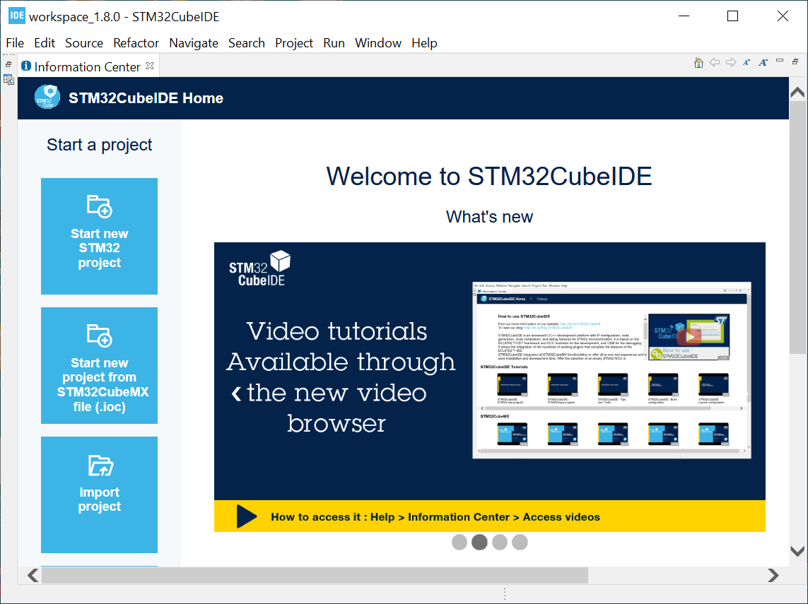
- When STM32CubeIDE is started for the first time, the main window shows the Information Center. It allows you to quickly create a new project or import an example project based on your hardware platform. In this post, we will start with a common baseline project which is already setup (available from github. See later). Go ahead to close the Information Center.
Import Project
- Download the baseline project from Gallium IO’s github link (https://github.com/galliumio/platform-stm32l475-disco-stm32ide.git). Here we use the STM32L475 IoT Discovery board as an example. You will find more platforms as they are added. We assume your local folder is named by default as platform-stm32l475-disco-stm32ide.
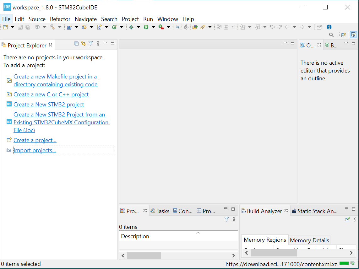
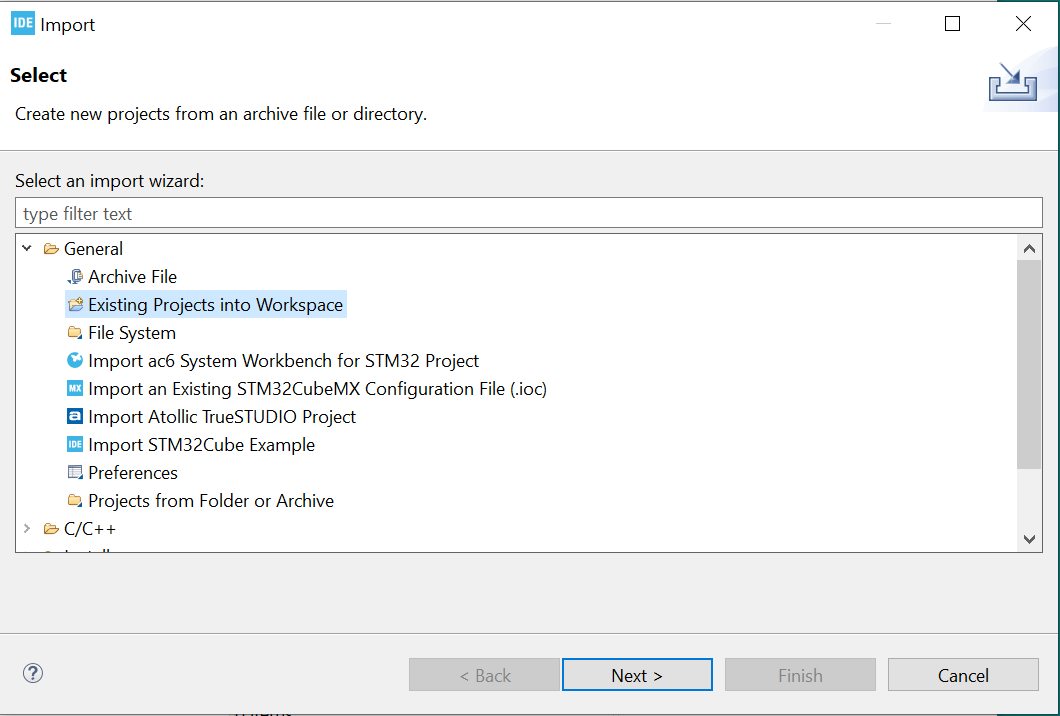
- Open Project Explorer by selecting from the top menu Window > Show View > Project Explorer. Click Import projects…
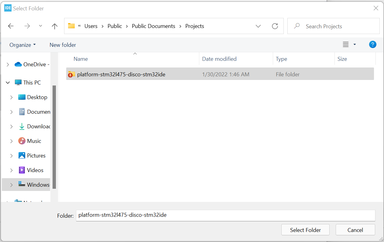
- Select General > Existing Projects into Workspace and click the Next button. Navigate to and select our example project folder (by default named as platform-stm32l475-disco-stm32ide). Click the Select Folder button.
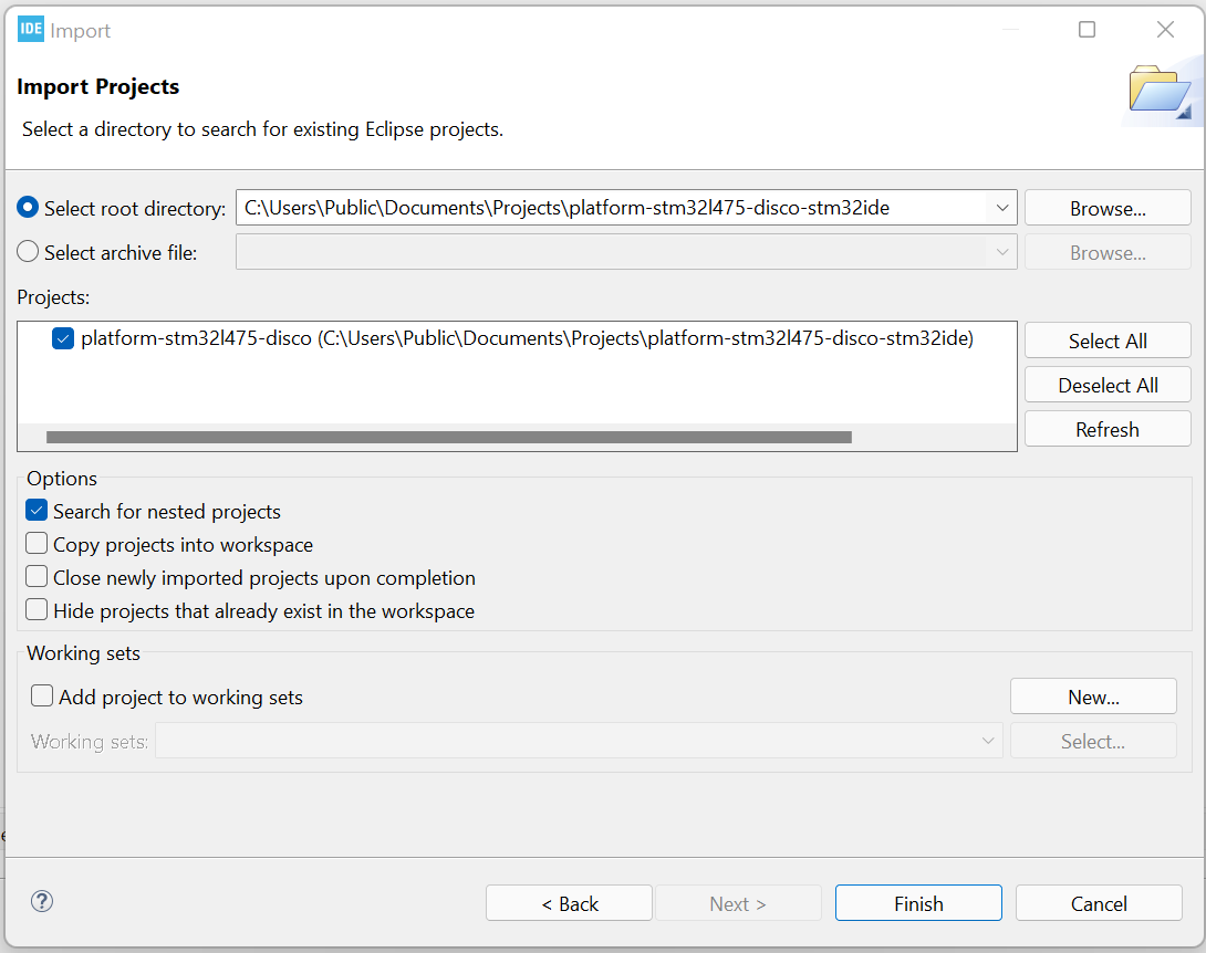
- Next, you will be presented the Import Projects window. You should see the project named platform-stm32l475-disco checked in the Projects box. Leave all options as default. In particular, DO NOT check the “Copy projects into workspace” option to keep the source in the original folder.
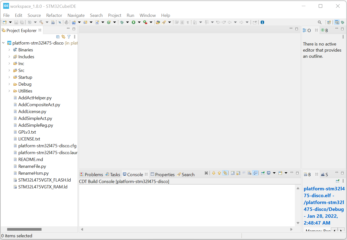
- Finally, the imported project platform-stm32l475-disco appears in the Project Explorer panel. Click the > icon next to the project name to expand the project folders.
Build Project
- Right-click on the project name in the Project Explorer to bring up the context menu. There are a few important items here:
- Build Project – To compile and link the source code to generate executable elf and bin files.
- Clean Project – To clean the project. You may run this before archiving your source folder, or to resolve any dependency issues.
- Properties – To configure project settings such as compiler and linker flags, environment variables, etc.
- Delete – To delete the project from the Project Explorer. Note: Make sure the option “Delete project contents on disk” is UNCHECKED if you want to keep the source folder on disk so that you can re-import the project later. This is useful when you need to switch between different source folders with the same project names.
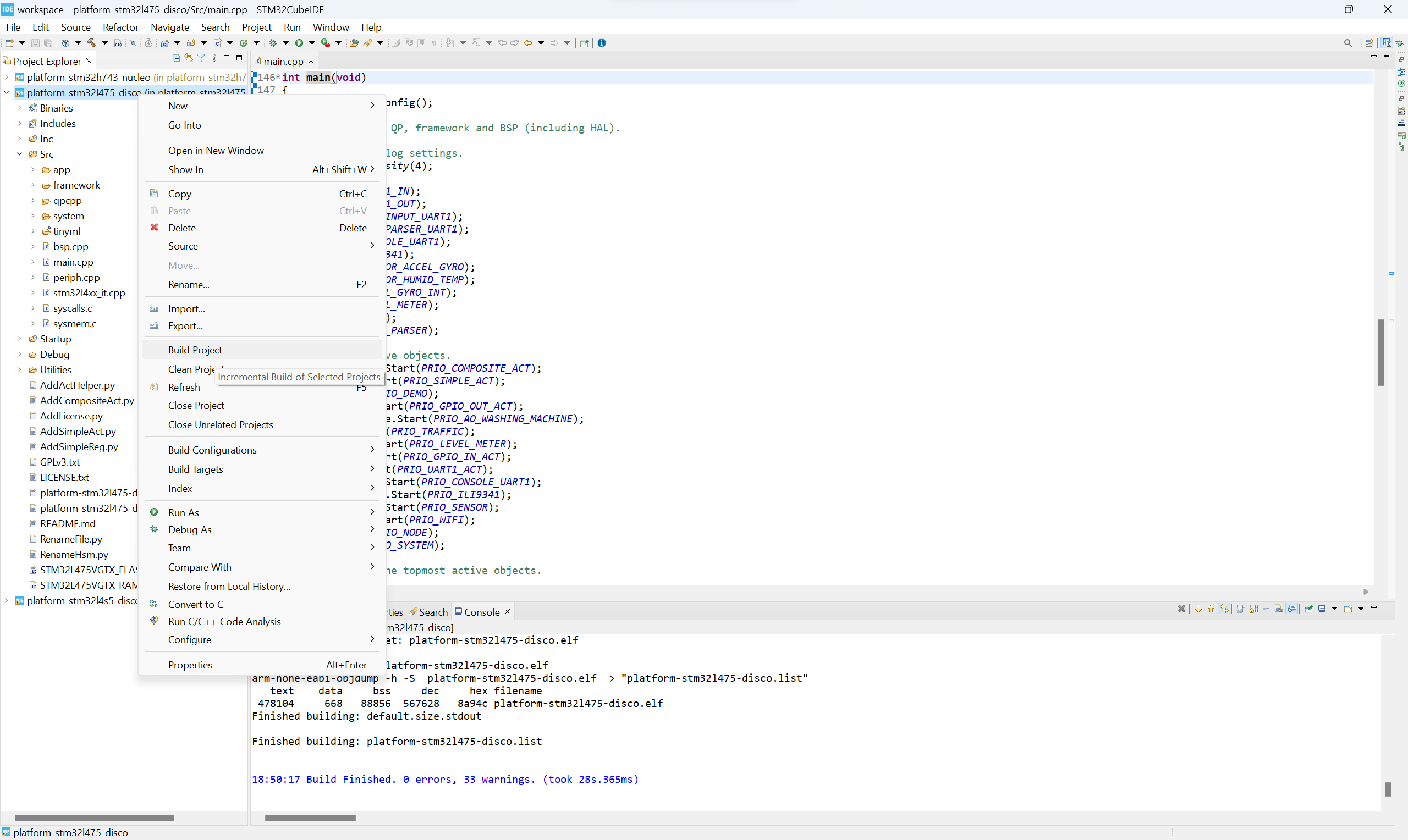
- Click Build Project and you should see a message similar to the following when it is built successfully:
arm-none-eabi-objcopy  -O binary  platform-stm32l475-disco.elf  "platform-stm32l475-disco.bin"
   text	   data	    bss	    dec	    hex	filename
 493916	    648	  81192	 575756	  8c90c	platform-stm32l475-disco.elf
Finished building: default.size.stdout
Finished building: platform-stm32l475-disco.bin
Finished building: platform-stm32l475-disco.list
15:25:20 Build Finished. 0 errors, 41 warnings. (took 21s.476ms)
It is OK to have warnings but there should be no errors. Most of the warnings are caused by 3rd party libraries. Now we have successfully built the firmware for our B-L475E-IOT01A discovery board. We are ready to move on to set up the debugger, download the firmware and run the program on the real hardware. Check out our next post at Debugging with STM32CubeIDE.
STM32CubeIDE is an all-in-one multi-OS development tool, which is part of the STM32Cube software ecosystem.

STM32CubeIDE is an advanced C/C++ development platform with IP configuration, code generation, code compilation, and debug features for STM32 microcontrollers. It is based on the ECLIPSE™/CDT framework and GCC toolchain for the development, and GDB for the debugging. It allows the integration of the hundreds of existing plugins that complete the features of the ECLIPSE™ IDE.
STM32CubeIDE integrates all STM32CubeMX functionalities to offer all-in-one tool experience and save installation and development time. After the selection of an empty STM32 MCU or preconfigured microcontroller from the selection of a board, the project is created and initialization code generated. At any time during the development, the user can return to the initialization and configuration of the IPs or middleware and regenerate the initialization code with no impact on the user code.
STM32CubeIDE includes build and stack analyzers that provide the user with useful information about project status and memory requirements.
STM32CubeIDE also includes standard and advanced debugging features including views of CPU core registers, memories, and peripheral registers, as well as live variable watch, Serial Wire Viewer interface, or fault analyzer.
Key Features
- Integration of STM32CubeMX that provides services for:
- STM32 microcontroller selection
- Pinout, clock, IP, and middleware configuration
- Project creation and generation of the initialization code
- Based on ECLIPSE™/CDT, with support of ECLIPSE™ add-ons, GNU C/C++ for Arm® toolchain and GDB debugger.
- Additional advanced debug features including:
- CPU core, IP register, and memory views
- Live variable watch view
- System analysis and real-time tracing (SWV)
- CPU fault analysis tool
- Support of ST-LINK (STMicroelectronics) and J-Link (SEGGER) debug probes
- Import project from Atollic® TrueSTUDIO® and AC6 System Workbench for STM32
- Multi-OS support: Windows®, Linux®, and macOS®
Installing STM32CubeIDE
For installing STM32CubeIDE in Linux, unzip the package and use the following command in same directory. For newer versions, replace the .sh file with new one.
sudo sh ./st-stm32cubeide_1.0.0_2872_20190423_2022_amd64.deb_bundle.sh
Connection bw ST-Link and Bluepill Board
Connect the Bluepill board and ST-Link as below


Connections
Vcc/3.3V of bluepill board – Pin 1 of ST-Link
SWDIO of bluepill board – Pin 7 of ST-Link
SWCLK of bluepill board – Pin 9 of ST-Link
Ground of bluepill board – Pin 4 of ST-Link

Create a Workspace
All your projects will be inside this workspace. So create a workspace.
Creating a new STM32 Project
We will now create a project for toggling an onboard led. For creating a new STM32 Project, select File ->STM32 Project

Select the MCU

Here I am using STM32F103C8 – Bluepill board

Give a name to your project

CubeMX window will open up. It is now integrated with the CubeIDE. Now we can configure the pins.

If there is a crystal on board, select RCC

RCC -> High speed Clock (HSE) -> Crystal/Ceramic Resonator. The RCC pins will turn Green.

I am using an ST-Link debug probe. So select SYS -> Debug -> Serial Wire. The Serial Wire Debug(SWD) pins will turn green.

Click on PC13.

Select GPIO Output and the pin will turn Green.

Click Clock Configuration. Here you can change the clock frequency if you want. The STM32F103 series has a maximum clock frequency of 72MHz. Also you can change the peripheral device clock frequencies also.

Here I am using the max clock frequency. Select HCLK and change it to 72MHz and click OK.

CubeMX will reconfigure the clock frequency.


Here I am ticking the Generate peripheral initialisations. The advantage is that separate .c/.h files will be generated for different peripherals instead of a single main.c file.
Then click on Device configuration Tool Code Generation. This will generate the HAL libraries for all the selected peripherals. Here we have included GPIO as output only. If you need other peripherals like UART, ADC etc in your project, configure them and HAL libraries will be generated for them as well.

The C/C++ perspective will open up. Here you can add/edit your code. If you add your code in the space provided for user code, it will be preserved when you regenerate the code.

I have added 2 lines of code for toggling the on board LED

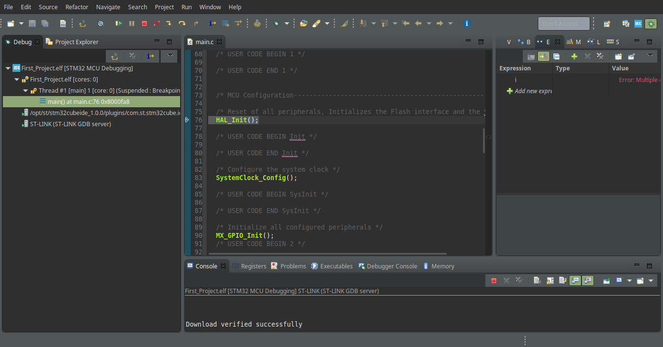
Highlight the project which you want to build. Here it is First_Project. Click on the Hammer icon. It will build your project. If there are no errors it will be as shown below.

For programming the MCU, click on the icon with the green bug -> Debug as

Select STM32MCU C/C++ Application

Click OK

And the Debug perspective will open up. Click on the Resume button and your code will start running. You can add break points, run step by step, add watch expressions for monitoring their value, monitor register values and lot more with ST-Link debug probe.
Sample projects available from here : https://github.com/jerryljames
You can buy it from here : https://www.elementzonline.com
Or you can mail us at : sales@elementzonline.com
Be sure to leave comments if you found this helpful 🙂
This article explains some of the basics of STM32CubeIDE support for STM32 MPU. STM32CubeIDE is an all-in-one multi-OS development tool, which is part of the STM32Cube ecosystem.
For more information about STM32CubeIDE, refer to its user guide.
Contents
- 1 STM32CubeIDE purpose
- 2 How to install STM32CubeIDE
- 3 How to get started with STM32CubeIDE
- 3.1 How to get started with STM32CubeIDE from scratch
- 3.2 How to migrate from SW4STM32 to STM32CubeIDE
- 4 Project structure
- 5 Arm® Cortex®-M debug on STM32 MPU device
- 5.1 Engineering mode
- 5.2 Production mode
- 5.3 ST-LINK sharing support
- 6 OpenSTLinux project support — Cortex®-A
- 6.1 How to install Yocto Project® SDK in STM32CubeIDE
- 6.2 How to manage OpenSTLinux projects
- 6.3 How to debug a user space application
- 6.4 How to debug a OP-TEE trusted application
- 7 Tips & tricks
1 STM32CubeIDE purpose[edit]
STM32CubeIDE is an advanced C/C++ development platform with peripheral configuration, code generation, code compilation, and debug features for STM32 microcontrollers and microprocessors. It is based on the Eclipse®/CDT framework, GCC toolchain for the development and GDB for the debugging.
It allows the integration of the hundreds of existing plugins that complete the features of the Eclipse® IDE. STM32CubeIDE integrates all STM32CubeMX functionalities to offer all-in-one tool experience, and save installation and development time.
With STM32CubeIDE, you can
- select the appropriate STM32 device corresponding to your needs
- configure the device using STM32CubeMX
- develop and debug applications on top of Arm® Cortex®-M
2 How to install STM32CubeIDE[edit]
STM32 MPU support, inside STM32CubeIDE, is available on Linux® and Windows® host PCs, but
it is NOT on macOS®.
| STM32CubeIDE for Linux® host PC | STM32CubeIDE for Windows® host PC | |
|---|---|---|
| Download |
Version 1.13.0
|
Version 1.13.0
|
| Installation guide |
|
|
| User manual |
|
|
| Detailed release note |
|
Minor releases may be available from the update site. Check chapter 10 in (UM2609) for more information on how to update STM32CubeIDE.
3 How to get started with STM32CubeIDE[edit]
This section links to two different how to articles depending on whether you are migrating from SW4STM32 to STM32CubeIDE or starting a new project with STM32CubeIDE.
3.1 How to get started with STM32CubeIDE from scratch[edit]
How to get started with STM32CubeIDE from scratch.
3.2 How to migrate from SW4STM32 to STM32CubeIDE[edit]
How to move from SW4STM32 to STM32CubeIDE.
4 Project structure[edit]
A hierarchical project structure is created together with the creation of an STM32 MPU project.
The project structure for single-core projects is flat.
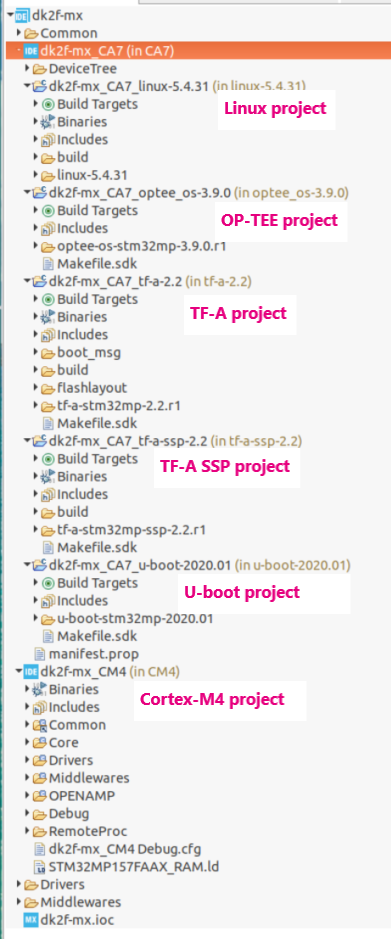
On the contrary, in a multi-core project, the hierarchical project structure is used. When the user creates or imports an STM32 MPU project, its structure is made of one root project together with sub-projects, referred to as STM32 MCU projects, for each core. A hierarchical structure example is shown below.
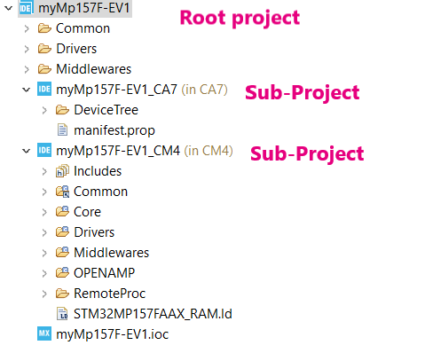
Hierarchical project structure
5 Arm® Cortex®-M debug on STM32 MPU device[edit]
Two modes are used to debug Arm® Cortex®-M firmware on STM32 MPU devices.
5.1 Engineering mode[edit]
Very powerful to debug preliminary Arm® Cortex®-M, the engineering mode implies a specific boot mode: the Engineering Boot Mode where only the Cortex®-M is started. Firmware is loaded via JTAG/SWD into its dedicated RAM.
This mode is not the default one. It must be set via the «Debug Configuration» menu, in the «Debugger» tab , with «through JTGA/SWD link (Engineering mode)» option selected.
| The initialization normally done in the Cortex®-A (such as clock tree setup or others) must be handled by the Arm® Cortex®-M. |
Debugging in engineering mode in an STM32 MPU device is very similar to a standard STM32 MCU debug in terms of functionality, except that in this case the Arm® Cortex®-M core has only one dedicated memory, no Flash memory type.
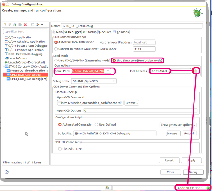
5.2 Production mode[edit]
Production mode targets a debug close to the final product.
It means to have an STM32 MPU board up and running on the Cortex®-A (Linux®) and a Cortex®-M firmware to debug (usually an STM32CubeIDE project).
The board, also named «target», is booted in the production mode from the Flash memory (the SD card); it is connected to the Host:
- via the Ethernet network, using an Ethernet cable or dedicated USB cable
- and via a USB cable to the ST-LINK probe, giving access to the JTAG/SWD and Linux® console
ST-LINK automatically brings support for Cortex®-A Linux® console via VCP (Virtual COM port). This enables the Target Status widget, visible on the bottom-right of STM32CubeIDE, allowing target IP address discovery. For production mode setup, it is recommended to get the target IP address discovered by the Target Status widget before creating the debug configuration.
This principle is depicted in the Debug Configuration screenshot below.
Network connection can be set up in two ways:
- Ethernet
- managed network: IP address attributed by DHCP server
- unmanaged network: IP address to be manually configured
- USB
- using the dedicated USB OTG connection for Ethernet point to point.
Debug is performed though the following workflow:
1. The firmware built binary is transferred to the target using the network (SSH protocol), more precisely to the Cortex®-A Linux® file system.
2. Firmware is loaded to Cortex®-M core using the “remoteproc” framework.
3. Finally the debug session is started via the JTAG/SWD connection
The production mode is the default one when you create a new debug configuration. It is automatically set via the «Debug Configuration» menu.
Debug configuration, production mode activated.
More information on how to use STM32CubeIDE target status are given in article How to use the Target Status widget in STM32CubeIDE.
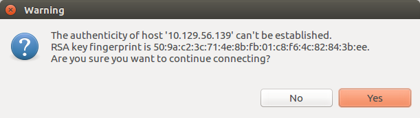
At debug launch, some specific pop-up appear:
- The SSH Password must be completed: the default one is root.
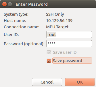
- The RSA key must be approved.
Defining an Arm® Cortex®-M project in an STM32 MPU context also means to define where are downloaded in the Arm® Cortex®-A Linux® file system:
- the Cortex®-M firmware: <ProjectName>.elf
- the load/unload script fw_cortex_m4.sh used by the STM32CubeIDE if present it can be customized
- and a README, informing a user having a direct connection onto the target.
This is the purpose of «Remote Path Setting» property which is linked to the project. Its default value at creation is /usr/local/project/<ProjectName>, but can also be changed using the Remote Settings properties item.
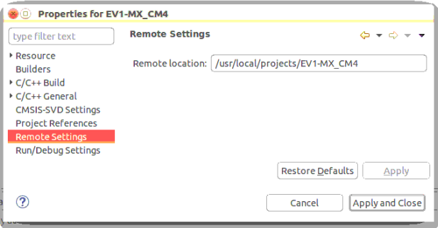
Inside project structure,directory «<ProjectName>_CM4/Core/RemoteProc/» defines the tree downloaded when debugging in the production mode.
5.3 ST-LINK sharing support[edit]
From STM32CubeIDE v1.2.0, it is possible to connect to an ST-LINK probe several applications, in parallel of openOCD. This support relies onto ‘ST-Link Server’.
It is enabled by checking Shared ST-Link inside «Debug Configuration > Debugger > ST-Link Client Setup».
6 OpenSTLinux project support — Cortex®-A[edit]
From release 1.4.0 on Linux® host ONLY, STM32CubeIDE supports OpenSTLinux projects and its associated Yocto Project® SDK.
Inside STM32CubeIDE, this support means two new Eclipse® plugins (SDK & Sources) to be installed, directly from the embedded CA7 project menu context:
- Setup OpenSTLinux
- Import an OpenSTLinux Project…
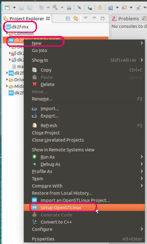
OpenSTLinux Contextual Menu
These Eclipse® plugins embed official packages from OpenSTLinux 2.0.
Note that a minimum disk space of 5 GBytes is needed under /tmp during the installation phase.
6.1 How to install Yocto Project® SDK in STM32CubeIDE[edit]
We focus in the article How to install the Yocto Project SDK in STM32CubeIDE on various ways to install the Yocto Project® SDK or point to an already existing SDK installation.
6.2 How to manage OpenSTLinux projects[edit]
All projects from OpenSTLinux can be imported inside STM32CubeIDE are available for compilation with Yocto Project® SDK.
Regarding project structure, these OpenSTLinux projects enrich the Cortex®-A part as depicted hereafter. Note that this support is starting from OpenSTLinux v2.0.
Hierarchical Project Structure with OpenSTLinux projects
6.3 How to debug a user space application[edit]
Release 1.6.0 provides support for creating, building and debugging projects aiming to run into the Linux® user space of STM32 MPUs. This includes executable, static and shared library.
6.4 How to debug a OP-TEE trusted application[edit]
Release 1.10.0 provides support for creating, building and debugging projects aiming to run into the Linux® user space of STM32 MPUs with support of secure service thanks to OP-TEE trusted application.
7 Tips & tricks[edit]
- How to use the Target Status widget in STM32CubeIDE
- How to set up proxy and P2P Ethernet connection with STM32CubeIDE
- How to setup target password in STM32CubeIDE
- How to copy and paste in the STM32CubeIDE console
- How to debug with Serial Wire Viewer tracing on STM32MP15