Несмотря на то, что эта модель позиционируется как “Карманный 3G роутер”, TL-MR3020 не включает в себя 3G-модем. Под обозначением 3G здесь подразумевается поддержка большинства USB 3G-модемов. OpenWrt, как и стандартная прошивка, поддерживает 3G-модемы. Роутер получает питание через разъём mini-USB(5V) и поставляется с сетевым USB-адаптером.
Роутер очень похож на TL-WR703N.
Входное напряжение: роутер функционирует корректно когда питается от напряжения выше чем 2.6V (определено экспериментально) вместо 5V. Следовательно, возможно питать устройство напрямую от Li-Ion батарей (3.7V) без использования внешнего адаптера 5V.
TL-MR3020 поддерживается стабильными версиями OpenWrt начиная с Attitude Adjusment.
Так же вы можете загрузить самый последний снэпшот или создать свой собственный из исходников.
![]() ВНИМАНИЕ: Тестовый trunk снэпшот может содержать не устраненные ошибки. Для обсуждения работы и получения информации касательно последних релизов обратитесь на форум.
ВНИМАНИЕ: Тестовый trunk снэпшот может содержать не устраненные ошибки. Для обсуждения работы и получения информации касательно последних релизов обратитесь на форум.
![]() ВНИМАНИЕ: Образ OpenWrt Chaos Calmer 15.05 уже содержит в себе LuCI (web-интерфейс). Из-за чего не остается свободного места для установки модулей, необходимых для организации extroot. Если Вы планируете использовать extroot для расширения внутренней памяти, Вам необходимо воспользоваться Image Builder для создания облегченного образа OpenWrt, с последующей доустановкой необходимых пакетов посредством opkg.
ВНИМАНИЕ: Образ OpenWrt Chaos Calmer 15.05 уже содержит в себе LuCI (web-интерфейс). Из-за чего не остается свободного места для установки модулей, необходимых для организации extroot. Если Вы планируете использовать extroot для расширения внутренней памяти, Вам необходимо воспользоваться Image Builder для создания облегченного образа OpenWrt, с последующей доустановкой необходимых пакетов посредством opkg.
Через Веб интерфейс (рекомендуется)
Подключите TL-MR3020 к компьютеру RJ-45 патч-кордом. В браузере пройдите по адресу http://192.168.0.254, введите имя и пароль (по умолчанию: admin / admin). Обновите прошивку стандартным методом указав файл openwrt-ar71xx-generic-tl-mr3020-v1-squashfs-factory.bin.
В процессе прошивки роутер перезагрузится и индикатор прогресса завершиться дважды. Дождитесь окончания,
и приступайте к базовой настройке как с любой свежеустановленной OpenWrt.
Прошивка через веб интерфейс успешно проверена на v1.0, v1.4 и v1.6 версиях tl-mr3020 и доступ через последовательный порт потребуется, только в случае если что-то пойдет не так.
Обратитесь на форум если у вас возникли проблемы.
Метод с использование Serial интерфейса и TFTP (для экспертов)
Для установки OpenWrt из консоли U-Boot вам потребуется установить TFTP сервер на ваш компьютер (tftp-hpa рекомендуется).
Затем загрузите образ прошивки в /srv/tftp (например), и запустите TFTP набрав tftpd -l -s /srv/tftp.
Соедините TL-MR3020 с компьютером используя serial интерфейс и подключите питание роутера.
После 1-2 секунд консоль покажет Autobooting in 1 seconds, когда вы увилите это введите tpl немедленно.
Using default environment

In:    serial
Out:   serial
Err:   serial
Net:   ag7240_enet_initialize...
No valid address in Flash. Using fixed address
No valid address in Flash. Using fixed address
: cfg1 0x5 cfg2 0x7114
eth0: 00:03:7f:09:0b:ad
ag7240_phy_setup
eth0 up
: cfg1 0xf cfg2 0x7214
eth1: 00:03:7f:09:0b:ad
athrs26_reg_init_lan
ATHRS26: resetting s26
ATHRS26: s26 reset done
ag7240_phy_setup
eth1 up
eth0, eth1
Autobooting in 1 seconds
[type tpl here]
Вы попадете в U-Boot-консоль, она отобразится строкой hornet> и будет ждать ввода. Вводите следующие команды:
hornet> setenv ipaddr <device-ip, eg. 192.168.1.111>
hornet> setenv serverip <server-ip, eg. 192.168.1.100>
hornet> tftpboot 0x80000000 openwrt-ar71xx-generic-tl-mr3020-v1-squashfs-factory.bin
eth1 link down
dup 1 speed 100
Using eth0 device
TFTP from server 192.168.1.100; our IP address is 192.168.1.111
Filename 'openwrt-ar71xx-generic-tl-mr3020-v1-squashfs-factory.bin'.
Load address: 0x80000000
Loading: #################################################################
         #################################################################
         #################################################################
         #################################################################
         #################################################################
         #################################################################
         #################################################################
         #################################################################
         #################################################################
         #################################################################
         #################################################################
         ######################################################
done
Bytes transferred = 3932160 (3c0000 hex)
hornet> erase 0x9f020000 +0x3c0000

First 0x2 last 0x3d sector size 0x10000                                                                                                        61
Erased 60 sectors
hornet> cp.b 0x80000000 0x9f020000 0x3c0000
Copy to Flash... write addr: 9f020000

done
hornet> bootm 9f020000
Автоматизация пошивки
Прошивать сотни роутеров через веб интерфейс может быть утомительным занятием. Вы можете использовать этот скрипт для автоматизации процесса:
#!/bin/bash

# Pass the firmware file to be flashed as the first parameter.
#
# The second curl call will time out, but it's expected. Once the
# script exits you can unplug the ethernet cable and proceed to the
# next router, but KEEP each router ON POWER until the new image is
# fully written! When flashing is done the router automatically
# reboots (as shown by all the leds flashing once).

curl \
  --user admin:admin \
  --user-agent 'Mozilla/5.0 (X11; Ubuntu; Linux i686; rv:12.0) Gecko/20100101 Firefox/12.0' \
  --referer 'http://192.168.0.254/userRpm/SoftwareUpgradeRpm.htm' \
  --form "Filename=@$1" -F 'Upgrade=Upgrade' \
  http://192.168.0.254/incoming/Firmware.htm > /dev/null

sleep 1

curl \
  --max-time 2 \
  --user admin:admin \
  --user-agent 'Mozilla/5.0 (X11; Ubuntu; Linux i686; rv:12.0) Gecko/20100101 Firefox/12.0' \
  --referer 'http://192.168.0.254/incoming/Firmware.htm' \
  http://192.168.0.254/userRpm/FirmwareUpdateTemp.htm >  /dev/null
![]() ВНИМАНИЕ:
ВНИМАНИЕ:
Для получения последней версии прошивки посетите страницу загрузок на сайте производителя, после чего замените ссылку из примера ниже на совместимую с вашей версией MR3020.
Последние прошивки на сайте идут со всроенным загрузчиком (в имени файла есть слово boot) и есть мнение, что заливка такой прошивки командой mtd убивает устройство. По моему опыту, необходим возврат именно на прошивку без загрузчика. Я залил версию прошивки без загрузчика (в имени файла нет слова boot) вот с таким именем mr3020nv1_en_3_14_2_up(120817).bin — и у меня всё заработало. Файл брал отсюда
Перед началом установите переключатель режимов работы роутеера в WISP. Без этого возможно будут проблемы с подключением после перезагрузки. Подключитесь через ssh/telnet/serial и используйте следующие команды:
# opkg update && opkg install unzip
# cd /tmp
# wget http://www.tp-link.com/Resources/software/TL-MR3020_V1.00_120817.zip
# unzip TL-MR3020*.zip
# mtd -r write mr3020*up*.bin firmware
через несколько секунд роутер перезагрузится. Откройте http://192.168.0.254/, введите имя и пароль admin / admin, и выполните сброс настроек в меню System Tools / Factory Defaults.
Первый запуск и настройка идентичны большинству других роутеров и детально описаны здесь.
Пожалуйста прочитайте раздел flash.layout для лучшего понимания строения памяти. Он содержит несколько разъяснений. Теперь давайте рассморим флеш память TL-MR3020:
| TP-Link MR3020 Flash Layout stock firmware | |||||
|---|---|---|---|---|---|
| Layer0 | spi0.0: 4096KiB | ||||
| Layer1 | mtd0 | mtd1 | mtd2 | mtd3 | mtd4 |
| Size in KiB | 128KiB | 1024KiB | 2816 KiB | 64KiB | 64KiB |
| Name | u-boot | kernel | rootfs | config | art |
| mountpoint | none | none | / | none | none |
| filesystem | none | none | SquashFS | none | none |
ART = Atheros Radio Test — раздел с RF-калибровочными данными wifi. Если он отсутствует или поврежден, wifi не будет работать.
Корпус состоит из двух частей: основная белая часть и серая крышка. Крышка держится на двух защелках, одна над входом питания mini-USB, другая на противоположной стороне на расстоянии 10 мм от лого “TP-LINK”. Крышка дополнительно приклеена к корпусу по всему периметру кроме мест где находятся защелки, вход RJ-45 и вход 3G. Начинать стоит от RJ-45 аккуратно поддевая крышку тонким, но прочным лезвием. Продвигайтесь в сторону 3G входа пока не достигните стороны с логотипом “TP-LINK”. Теперь у вас уже должно получиться заглянуть внутрь корпуса.
Оставшуюся сторону с индикаторами нужно отрывать с осторожностью, т. к. пластиковые проводники света хрупкие и уходят вглубь корпуса, до самых светодиодов на плате. Их легко согнуть и сломать, когда вы слишком усердно нажимаете на ваш инструмент. Лучше отрывать оставшуюся часть крышки легким раскачиванием. При аккуратном извлечении крышка должна без особых проблем встать на прежнее место после небольшой зачистки.


Распиновка
Pin 1 четко обозначен на плате.
Для надежного соединения возможно вам придется подключить подтягивающий 10k резистор между TX и VCC. Дело в том, что контакт TX соединен с делителем напряжения (2×5.6k) и между реальным контактом и TX пином помещен конденсатор. Некоторые serial адаптеры могут работать без подтягивающего резистора (например адаптер на базе ST3232), для работы других он безусловно нужен (например для FTDI FT232RL).
Если у вас нет serial адаптера, вы можете сделать его из кабеля CA-42 или DKU-5 от телефонов Nokia как описано здесь. Относительно дешевой, рабочей альтернативой будет использование решений от SparkFun: FTDI Basic Breakout 3.3V и FTDI Serial Cable 3.3V.
Параметры соединения с использованием serial интерфейса следующие:
Bits per second: 115200
Data bits: 8
Stop bits: 1
Parity: None
Flow control: None
Если вы используете OS Linux или Mac, то для доступа к serial интерфейсу проще всего использовать команду screen. Она по умолчанию включена в OS X, но для систем на базе Linux может потребоваться дополнительная ее установка. После установки наберите в терминале:
screen /dev/[device name] 115200
Где [device name] — это имя вашего serial адаптера (обычно tty.usbserial* для Mac и ttyUSB* для Linux). Для выхода из режима screen нажмите CTRL-a, затем CTRL-k, затем y.
Консоль загрузчика U-Boot
Пароль для входа в командный режим U-Boot tpl. Вам нужно ввести его очень быстро когда увидите на экране:
[...]
ag7240_phy_setup
eth1 up
eth0, eth1
Autobooting in 1 seconds
[type tpl here]
После входа в командный режим наберите help для получения списка доступных команд.
hornet> help
?       - alias for 'help'
bootm   - boot application image from memory
cp      - memory copy
erase   - erase FLASH memory
help    - print online help
md      - memory display
mm      - memory modify (auto-incrementing)
mtest   - simple RAM test
mw      - memory write (fill)
nm      - memory modify (constant address)
printenv- print environment variables
progmac - Set ethernet MAC addresses
reset   - Perform RESET of the CPU
setenv  - set environment variables
tftpboot- boot image via network using TFTP protocol
version - print monitor version
Консоль Linux
После того как оригинальная прошивка будет загружена вы можете нажать return чтобы залогиниться в систему.
Пароль для доступа к root шелу 5up:
TL-MR3020 mips #185 Fri Oct 21 16:26:50 CST 2011 (none)
TL-MR3020 login: root
password: 5up
→ port.gpio
The AR933x platform provides 30 GPIOs. Some of them are used by the router for status LEDs, buttons and other stuff. The table below shows the results of some investigation:
| Voltage level at GPIO in output-mode | gpioX/value in input-mode when GPIO is: | ||||||
|---|---|---|---|---|---|---|---|
| GPIO | Common Name | PCB Name | gpioX/value=1 | gpioX/value=0 | Floating | Pulled to GND | Pulled to Vcc |
| 0 | WLAN LED | LED4 | |||||
| 1 | unused Pulled to VCC | R2 and R5 | |||||
| 2 | |||||||
| 3 | |||||||
| 4 | |||||||
| 5 | |||||||
| 6 | R16 | ||||||
| 7 | unused Pulled to ground | R15 | |||||
| 8 | USB power(?) | R18 | |||||
| 9 | |||||||
| 10 | |||||||
| 11 | WPS button | ||||||
| 12 | |||||||
| 13 | |||||||
| 14 | |||||||
| 15 | |||||||
| 16 | |||||||
| 17 | Ethernet LED | LED5 | |||||
| 18 | Sliding Sw. | ||||||
| 19 | |||||||
| 20 | Sliding Sw. | ||||||
| 21 | |||||||
| 22 | |||||||
| 23 | |||||||
| 24 | |||||||
| 25 | |||||||
| 26 | WPS LED | LED2 | |||||
| 27 | Internet LED | LED3 | |||||
| 28 | |||||||
| 29 | unused Pulled to ground | R17 |
To make the GPIOs available via sysfs, the required ones have to be exported to userspace, as it is explained on a page of the Squidge-Project. Kernel modules occupying that resource need to be removed before (e.g. “leds-gpio” and “gpio-buttons”). In output-mode, voltage levels of the GPIOs were measured against GND, after the value 1 or 0 had been written to /sys/class/gpio/gpioX/value. In input-mode, the value of the file /sys/class/gpio/gpioX/value was read when the GPIO was floating (initial state), pulled to GND or pulled to Vcc.
The sliding switch has the following truth table:
| Mode Switch | GPIO18 | GPIO20 |
|---|---|---|
| 3G | 1 | 0 |
| WISP | 0 | 1 |
| AP | 1 | 1 |
How to configure LEDs in general, see the LED section in the led_configuration.
The TL-MR3020 has 5 LEDs:
| LED name | LED print | Internal name | Trigger |
|---|---|---|---|
| Power | Power symbol | N/A (fixed supply) | N/A |
| 3G | Internet symbol | tl-mr3020:green:3g | USB:1-1 |
| Wireless LAN | WLAN symbol | tl-mr3020:green:wlan | phy0tpt |
| LAN | LAN symbol | tl-mr3020:green:lan | netdev:eth0 |
| WPS | WPS | tl-mr3020:green:wps | User preference |
→ hardware.button
The TP-Link TL-MR3020 has one button and one sliding switch with three positions:
| BUTTON | Event |
|---|---|
| Sliding Switch | BTN_0 and BTN_1 |
| WPS Button | WPS |
The WPS button is located at the top (illuminated by the WPS LED) and can be easily pressed with a finger. The sliding switch is located at the side and has three positions: 3G, WISP, AP.


If you want to add an external antenna connector or would like to know more about the MR3020 power consumption in different op-states you can find more info Apollo-NG MR3020 External Antenna Hack
USB port and monitoring Serial Console via USB-Serial
The USB port on the TL-MR3020 is not compatible with USB1 devices (aka full speed) and only works properly with USB2 (aka high speed) devices. You can however plug a USB-Serial adapter as long as you plug that through a <$10 USB2. While you’re at it, use another USB port to plug in a USB key and write data there (like serial console logs) so as not to wear out the built in flash.
See this page for more tips and how to create a serial console server out of your TL-MR3020:
http://marc.merlins.org/perso/linux/post_2012-12-05_Serial-Console-With-WR703N.html
U-Boot 1.1.4 (Aug 17 2011 — 09:25:09)
AP121-2MB (ar9330) U-boot
DRAM: 32 MB
led turning on for 1s…
id read 0x100000ff
flash size 4194304, sector count = 64
Flash: 4 MB
Using default environment
In: serial
Out: serial
Err: serial
Net: ag7240_enet_initialize…
No valid address in Flash. Using fixed address
No valid address in Flash. Using fixed address
: cfg1 0x5 cfg2 0x7114
eth0: 00:03:7f:09:0b:ad
ag7240_phy_setup
eth0 up
: cfg1 0xf cfg2 0x7214
eth1: 00:03:7f:09:0b:ad
athrs26_reg_init_lan
ATHRS26: resetting s26
ATHRS26: s26 reset done
ag7240_phy_setup
eth1 up
eth0, eth1
Autobooting in 1 seconds
## Booting image at 9f020000 …
Uncompressing Kernel Image … OK
Starting kernel …
Booting AR9330(Hornet)…
Linux version 2.6.31—LSDK-9.2.0.312 (root@bogon) (gcc version 4.3.3 (GCC) ) #185 Fri Oct 21 16:26:50 CST 2011
flash_size passed from bootloader = 4
CPU revision is: 00019374 (MIPS 24Kc)
Determined physical RAM map:
memory: 02000000 @ 00000000 (usable)
User-defined physical RAM map:
memory: 02000000 @ 00000000 (usable)
Zone PFN ranges:
Normal 0x00000000 -> 0x00002000
Movable zone start PFN for each node
early_node_map[1] active PFN ranges
0: 0x00000000 -> 0x00002000
Built 1 zonelists in Zone order, mobility grouping on. Total pages: 8128
Kernel command line: console=ttyS0,115200 root=31:02 rootfstype=squashfs init=/sbin/init mtdparts=ar7240-nor0:128k(u-boot),1024k(kernel),2816(rootfs),64k(config),64k(ART) mem=32M
PID hash table entries: 128 (order: 7, 512 bytes)
Dentry cache hash table entries: 4096 (order: 2, 16384 bytes)
Inode-cache hash table entries: 2048 (order: 1, 8192 bytes)
Primary instruction cache 64kB, VIPT, 4-way, linesize 32 bytes.
Primary data cache 32kB, 4-way, VIPT, cache aliases, linesize 32 bytes
Writing ErrCtl register=00000000
Readback ErrCtl register=00000000
Memory: 29864k/32768k available (1889k kernel code, 2904k reserved, 524k data, 116k init, 0k highmem)
Hierarchical RCU implementation.
NR_IRQS:128
plat_time_init: plat time init done
Calibrating delay loop… 266.24 BogoMIPS (lpj=532480)
Mount-cache hash table entries: 512
NET: Registered protocol family 16
===== ar7240_platform_init: 0
Whoops! This kernel is for product mr3020 v1.0!
bio: create slab <bio-0> at 0
SCSI subsystem initialized
usbcore: registered new interface driver usbfs
usbcore: registered new interface driver hub
usbcore: registered new device driver usb
NET: Registered protocol family 2
IP route cache hash table entries: 1024 (order: 0, 4096 bytes)
TCP established hash table entries: 1024 (order: 1, 8192 bytes)
TCP bind hash table entries: 1024 (order: 0, 4096 bytes)
TCP: Hash tables configured (established 1024 bind 1024)
TCP reno registered
NET: Registered protocol family 1
AR7240 GPIOC major 0
squashfs: version 4.0 (2009/01/31) Phillip Lougher
NTFS driver 2.1.29 [Flags: R/O].
msgmni has been set to 58
alg: No test for lzma (lzma-generic)
alg: No test for stdrng (krng)
io scheduler noop registered
io scheduler anticipatory registered
io scheduler deadline registered
io scheduler cfq registered (default)
Serial: 8250/16550 driver, 1 ports, IRQ sharing disabled
ttyS0: detected caps 00000000 should be 00000100
serial8250.0: ttyS0 at MMIO 0xb8020000 (irq = 19) is a 16550A
console [ttyS0] enabled
PPP generic driver version 2.4.2
NET: Registered protocol family 24
cmdlinepart partition parsing not available
set partition boot
set partition kernel
set partition rootfs
set partition config
set partition art
set partition ÿ
Searching for RedBoot partition table
5 RedBoot partitions found on MTD device ar7240-nor0
Creating 5 MTD partitions on «ar7240-nor0»:
0x000000000000-0x000000020000 : «boot»
0x000000020000-0x000000120000 : «kernel»
0x000000120000-0x0000003e0000 : «rootfs»
0x0000003e0000-0x0000003f0000 : «config»
0x0000003f0000-0x000000400000 : «art»
->Oops: flash id 0x10215 .
ehci_hcd: USB 2.0 ‘Enhanced’ Host Controller (EHCI) Driver
Port Status 1c000004
ar7240-ehci ar7240-ehci.0: ATH EHCI
ar7240-ehci ar7240-ehci.0: new USB bus registered, assigned bus number 1
ehci_reset Intialize USB CONTROLLER in host mode: 3
ehci_reset Port Status 1c000000
ar7240-ehci ar7240-ehci.0: irq 3, io mem 0x1b000000
ehci_reset Intialize USB CONTROLLER in host mode: 3
ehci_reset Port Status 1c000000
ar7240-ehci ar7240-ehci.0: USB 2.0 started, EHCI 1.00
usb usb1: configuration #1 chosen from 1 choice
hub 1-0:1.0: USB hub found
hub 1-0:1.0: 1 port detected
TCP cubic registered
NET: Registered protocol family 17
802.1Q VLAN Support v1.8 Ben Greear <greearb@candelatech.com>
All bugs added by David S. Miller <davem@redhat.com>
ar7240wdt_init: Registering WDT success
VFS: Mounted root (squashfs filesystem) readonly on device 31:2.
Freeing unused kernel memory: 116k freed
init started: BusyBox v1.01 (2011.04.01-07:49+0000) multi-call binary
This Board use 2.6.31
xt_time: kernel timezone is -0000
nf_conntrack version 0.5.0 (512 buckets, 5120 max)
ip_tables: (C) 2000-2006 Netfilter Core Team
insmod: cannot open module `/lib/modules/2.6.31/kernel/iptable_raw.ko’: No such file or directory
insmod: cannot open module `/lib/modules/2.6.31/kernel/flashid.ko’: No such file or directory
PPPoL2TP kernel driver, V1.0
PPTP driver version 0.8.3
insmod: cannot open module `/lib/modules/2.6.31/kernel/harmony.ko’: No such file or directory
(none) mips #185 Now flash open!
Fri Oct 21 16:26:50 CST 2011 (none)
(none) login: Now flash open!
ATHR_GMAC: Length per segment 1536
ATHR_GMAC: fifo cfg 3 01f00140
ATHR_GMAC: Mac address for unit 1:bf1f0006
ATHR_GMAC: 6e:09:80:e4:67:1b
ATHR_GMAC: Max segments per packet : 1
ATHR_GMAC: Max tx descriptor count : 40
ATHR_GMAC: Max rx descriptor count : 96
ATHR_GMAC: Mac capability flags : 4D83
ATHR_GMAC: Mac address for unit 0:bf1f0000
ATHR_GMAC: 12:03:cb:60:38:f7
ATHR_GMAC: Max segments per packet : 1
ATHR_GMAC: Max tx descriptor count : 40
ATHR_GMAC: Max rx descriptor count : 252
ATHR_GMAC: Mac capability flags : 4403
athr_gmac_ring_alloc Allocated 640 at 0x81e79800
athr_gmac_ring_alloc Allocated 4032 at 0x81d63000
Setting Drop CRC Errors, Pause Frames and Length Error frames
Setting PHY…mac 0
athr_gmac_ring_alloc Allocated 640 at 0x81e79400
athr_gmac_ring_alloc Allocated 1536 at 0x81f22000
athr_gmac_mii_setup: MDC check failed
Setting Drop CRC Errors, Pause Frames and Length Error frames
ATHRS26: resetting s26
ATHRS26: s26 reset done
Setting PHY…mac 1
device eth0 entered promiscuous mode
Now flash open!
nf_conntrack_rtsp v0.6.21 loading
nf_nat_rtsp v0.6.21 loading
asf: module license ‘Proprietary’ taints kernel.
Disabling lock debugging due to kernel taint
ath_hal: 0.9.17.1 (AR9380, DEBUG, REGOPS_FUNC, WRITE_EEPROM, 11D)
ath_rate_atheros: Copyright (c) 2001-2005 Atheros Communications, Inc, All Rights Reserved
ath_dev: Copyright (c) 2001-2007 Atheros Communications, Inc, All Rights Reserved
ath_ahb: 9.2.0_U5.508 (Atheros/multi-bss)
Boostrap clock 25MHz
ar9300RadioAttach: Need analog access recipe!!
Restoring Cal data from Flash
ath_get_caps[4735] rx chainmask mismatch actual 1 sc_chainmak 0
ath_get_caps[4710] tx chainmask mismatch actual 1 sc_chainmak 0
wifi0: Atheros 9380: mem=0xb8100000, irq=2
wlan_vap_create : enter. devhandle=0x80c042c0, opmode=IEEE80211_M_HOSTAP, flags=0x1
wlan_vap_create : exit. devhandle=0x80c042c0, opmode=IEEE80211_M_HOSTAP, flags=0x1.
VAP device ath0 created
DES SSID SET=TP-LINK_POCKET_3020_3ABB7A
ieee80211_scan_unregister_event_handler: Failed to unregister evhandler=c0a048a0 arg=81e9e2c0
wlan_vap_delete : enter. vaphandle=0x81e9c000
wlan_vap_delete : exit. vaphandle=0x81e9c000
wlan_vap_create : enter. devhandle=0x80c042c0, opmode=IEEE80211_M_HOSTAP, flags=0x1
wlan_vap_create : exit. devhandle=0x80c042c0, opmode=IEEE80211_M_HOSTAP, flags=0x1.
VAP device ath0 created
DES SSID SET=TP-LINK_POCKET_3020_3ABB7A
ieee80211_ioctl_siwmode: imr.ifm_active=393856, new mode=3, valid=1
WARNING: Fragmentation with HT mode NOT ALLOWED!!
device ath0 entered promiscuous mode
br0: port 2(ath0) entering forwarding state
ieee80211_ioctl_siwmode: imr.ifm_active=1442432, new mode=3, valid=1
br0: port 2(ath0) entering disabled state
DES SSID SET=TP-LINK_POCKET_3020_3ABB7A
br0: port 2(ath0) entering forwarding state
gpio_tricolor_led_write 699
green_led_onoff = 1
TL-MR3020 mips #185 Fri Oct 21 16:26:50 CST 2011 (none)
TL-MR3020 login:
U-Boot 1.1.4 (Sep 21 2015 — 17:19:07)
AP121 (ar9330) U-boot
DRAM: 32 MB
led turning on for 1s…
id read 0x100000ff
flash size 4194304, sector count = 64
Flash: 4 MB
Using default environment
In: serial
Out: serial
Err: serial
Net: ag7240_enet_initialize…
No valid address in Flash. Using fixed address
No valid address in Flash. Using fixed address
: cfg1 0x5 cfg2 0x7114
eth0: 00:03:7f:09:0b:ad
ag7240_phy_setup
eth0 up
: cfg1 0xf cfg2 0x7214
eth1: 00:03:7f:09:0b:ad
athrs26_reg_init_lan
ATHRS26: resetting s26
ATHRS26: s26 reset done
ag7240_phy_setup
eth1 up
eth0, eth1
auto update firmware: is_auto_upload_firmware = 0!
Autobooting in 1 seconds
## Booting image at 9f020000 …
Uncompressing Kernel Image … OK
Starting kernel …
[ 0.000000] Linux version 4.14.171 (builder@buildhost) (gcc version 7.5.0 (OpenWrt GCC 7.5.0 r10947-65030d81f3)) #0 Thu Feb 270
[ 0.000000] bootconsole [early0] enabled
[ 0.000000] CPU0 revision is: 00019374 (MIPS 24Kc)
[ 0.000000] MIPS: machine is TP-Link TL-MR3020 V1
[ 0.000000] SoC: Atheros AR9330 rev 1
[ 0.000000] Determined physical RAM map:
[ 0.000000] memory: 02000000 @ 00000000 (usable)
[ 0.000000] Initrd not found or empty — disabling initrd
[ 0.000000] Primary instruction cache 64kB, VIPT, 4-way, linesize 32 bytes.
[ 0.000000] Primary data cache 32kB, 4-way, VIPT, cache aliases, linesize 32 bytes
[ 0.000000] Zone ranges:
[ 0.000000] Normal [mem 0x0000000000000000-0x0000000001ffffff]
[ 0.000000] Movable zone start for each node
[ 0.000000] Early memory node ranges
[ 0.000000] node 0: [mem 0x0000000000000000-0x0000000001ffffff]
[ 0.000000] Initmem setup node 0 [mem 0x0000000000000000-0x0000000001ffffff]
[ 0.000000] random: get_random_bytes called from 0x804776ec with crng_init=0
[ 0.000000] Built 1 zonelists, mobility grouping on. Total pages: 8128
[ 0.000000] Kernel command line: console=ttyATH0,115200 rootfstype=squashfs,jffs2
[ 0.000000] PID hash table entries: 128 (order: -3, 512 bytes)
[ 0.000000] Dentry cache hash table entries: 4096 (order: 2, 16384 bytes)
[ 0.000000] Inode-cache hash table entries: 2048 (order: 1, 8192 bytes)
[ 0.000000] Writing ErrCtl register=00000000
[ 0.000000] Readback ErrCtl register=00000000
[ 0.000000] Memory: 26436K/32768K available (3545K kernel code, 143K rwdata, 492K rodata, 1188K init, 203K bss, 6332K reserved)
[ 0.000000] SLUB: HWalign=32, Order=0-3, MinObjects=0, CPUs=1, Nodes=1
[ 0.000000] NR_IRQS: 51
[ 0.000000] CPU clock: 400.000 MHz
[ 0.000000] clocksource: MIPS: mask: 0xffffffff max_cycles: 0xffffffff, max_idle_ns: 9556302233 ns
[ 0.000014] sched_clock: 32 bits at 200MHz, resolution 5ns, wraps every 10737418237ns
[ 0.007579] Calibrating delay loop… 265.42 BogoMIPS (lpj=1327104)
[ 0.092176] pid_max: default: 32768 minimum: 301
[ 0.096903] Mount-cache hash table entries: 1024 (order: 0, 4096 bytes)
[ 0.102950] Mountpoint-cache hash table entries: 1024 (order: 0, 4096 bytes)
[ 0.115925] clocksource: jiffies: mask: 0xffffffff max_cycles: 0xffffffff, max_idle_ns: 19112604462750000 ns
[ 0.124017] futex hash table entries: 256 (order: -1, 3072 bytes)
[ 0.129909] pinctrl core: initialized pinctrl subsystem
[ 0.138275] NET: Registered protocol family 16
[ 0.174344] clocksource: Switched to clocksource MIPS
[ 0.179418] NET: Registered protocol family 2
[ 0.183551] TCP established hash table entries: 1024 (order: 0, 4096 bytes)
[ 0.188949] TCP bind hash table entries: 1024 (order: 0, 4096 bytes)
[ 0.195000] TCP: Hash tables configured (established 1024 bind 1024)
[ 0.201243] UDP hash table entries: 256 (order: 0, 4096 bytes)
[ 0.206675] UDP-Lite hash table entries: 256 (order: 0, 4096 bytes)
[ 0.212933] NET: Registered protocol family 1
[ 0.222552] Crashlog allocated RAM at address 0x1f00000
[ 0.228215] workingset: timestamp_bits=30 max_order=13 bucket_order=0
[ 0.241410] squashfs: version 4.0 (2009/01/31) Phillip Lougher
[ 0.245670] jffs2: version 2.2 (NAND) (SUMMARY) (LZMA) (RTIME) (CMODE_PRIORITY) (c) 2001-2006 Red Hat, Inc.
[ 0.269461] io scheduler noop registered
[ 0.271832] io scheduler deadline registered (default)
[ 0.277336] ar7200-usb-phy usb-phy: phy reset is missing
[ 0.282460] pinctrl-single 18040028.pinmux: 64 pins at pa b8040028 size 8
[ 0.289853] Serial: 8250/16550 driver, 16 ports, IRQ sharing enabled
[ 0.298538] 18020000.uart: ttyATH0 at MMIO 0x18020000 (irq = 9, base_baud = 1562500) is a AR933X UART
[ 0.306467] console [ttyATH0] enabled
[ 0.306467] console [ttyATH0] enabled
[ 0.313250] bootconsole [early0] disabled
[ 0.313250] bootconsole [early0] disabled
[ 0.333803] m25p80 spi0.0: s25sl032p (4096 Kbytes)
[ 0.337291] 4 fixed-partitions partitions found on MTD device spi0.0
[ 0.343484] Creating 4 MTD partitions on «spi0.0»:
[ 0.348296] 0x000000000000-0x000000020000 : «u-boot»
[ 0.354571] 0x000000020000-0x0000003e0000 : «firmware»
[ 0.359706] 2 tplink-fw partitions found on MTD device firmware
[ 0.364233] Creating 2 MTD partitions on «firmware»:
[ 0.369284] 0x000000000000-0x00000015bfb2 : «kernel»
[ 0.375296] 0x00000015bfb4-0x0000003c0000 : «rootfs»
[ 0.380153] mtd: device 3 (rootfs) set to be root filesystem
[ 0.384841] 1 squashfs-split partitions found on MTD device rootfs
[ 0.390907] 0x000000380000-0x0000003c0000 : «rootfs_data»
[ 0.397435] 0x0000003e0000-0x0000003f0000 : «config»
[ 0.402352] 0x0000003f0000-0x000000400000 : «art»
[ 0.408090] libphy: Fixed MDIO Bus: probed
[ 0.744824] libphy: ag71xx_mdio: probed
[ 0.748236] libphy: ar8xxx-mdio: probed
[ 0.753691] switch0: Atheros AR724X/AR933X built-in rev. 2 switch registered on mdio-bus.0
[ 1.136098] ag71xx 19000000.eth: connected to PHY at mdio-bus.0:1f:04 [uid=004dd041, driver=Generic PHY]
[ 1.145172] eth0: Atheros AG71xx at 0xb9000000, irq 4, mode: mii
[ 1.153525] NET: Registered protocol family 10
[ 1.163505] Segment Routing with IPv6
[ 1.165941] NET: Registered protocol family 17
[ 1.170234] bridge: filtering via arp/ip/ip6tables is no longer available by default. Update your scripts to load br_netfilter.
[ 1.183988] 8021q: 802.1Q VLAN Support v1.8
[ 1.191043] usb_vbus: disabling
[ 1.199804] VFS: Mounted root (squashfs filesystem) readonly on device 31:3.
[ 1.214564] Freeing unused kernel memory: 1188K
[ 1.217636] This architecture does not have kernel memory protection.
[ 2.554368] random: fast init done
[ 2.910873] init: Console is alive
[ 2.913163] init: — watchdog —
[ 4.779562] kmodloader: loading kernel modules from /etc/modules-boot.d/*
[ 5.119709] usbcore: registered new interface driver usbfs
[ 5.123854] usbcore: registered new interface driver hub
[ 5.129278] usbcore: registered new device driver usb
[ 5.145706] ehci_hcd: USB 2.0 ‘Enhanced’ Host Controller (EHCI) Driver
[ 5.159149] ci_hdrc ci_hdrc.0: EHCI Host Controller
[ 5.162652] ci_hdrc ci_hdrc.0: new USB bus registered, assigned bus number 1
[ 5.194364] ci_hdrc ci_hdrc.0: USB 2.0 started, EHCI 1.00
[ 5.199559] hub 1-0:1.0: USB hub found
[ 5.202656] hub 1-0:1.0: 1 port detected
[ 5.208421] kmodloader: done loading kernel modules from /etc/modules-boot.d/*
[ 5.224891] init: — preinit —
[ 7.762373] random: jshn: uninitialized urandom read (4 bytes read)
[ 8.213085] random: jshn: uninitialized urandom read (4 bytes read)
[ 8.283912] random: jshn: uninitialized urandom read (4 bytes read)
[ 8.616828] IPv6: ADDRCONF(NETDEV_UP): eth0: link is not ready
Press the [f] key and hit [enter] to enter failsafe mode
Press the [1], [2], [3] or [4] key and hit [enter] to select the debug level
[ 12.270601] jffs2: Too few erase blocks (4)
[ 12.273953] mount_root: failed to mount -t jffs2 /dev/mtdblock4 /tmp/overlay: Invalid argument
[ 12.282467] mount_root: overlay filesystem has not been fully initialized yet
[ 12.289623] mount_root: switching to jffs2 overlay
[ 12.294007] mount_root: switching to jffs2 failed — fallback to ramoverlay
[ 12.335584] urandom-seed: Seed file not found (/etc/urandom.seed)
[ 13.133199] procd: — early —
[ 13.134885] procd: — watchdog —
[ 13.756723] procd: — watchdog —
[ 13.758857] procd: — ubus —
[ 14.190831] urandom_read: 5 callbacks suppressed
[ 14.190844] random: ubusd: uninitialized urandom read (4 bytes read)
[ 14.202193] random: ubusd: uninitialized urandom read (4 bytes read)
[ 14.209264] procd: — init —
Please press Enter to activate this console.
[ 15.640541] kmodloader: loading kernel modules from /etc/modules.d/*
[ 15.668208] Loading modules backported from Linux version v4.19.98-0-gd183c8e2647a
[ 15.674412] Backport generated by backports.git v4.19.98-1-0-g8204eb99
[ 15.701962] nf_conntrack version 0.5.0 (1024 buckets, 4096 max)
[ 15.875660] xt_time: kernel timezone is -0000
[ 15.937320] ip_tables: (C) 2000-2006 Netfilter Core Team
[ 16.145438] ieee80211 phy0: Atheros AR9330 Rev:1 mem=0xb8100000, irq=2
[ 16.265011] kmodloader: done loading kernel modules from /etc/modules.d/*
[ 16.768009] urngd: v1.0.2 started.
[ 17.596458] random: crng init done
[ 39.967161] IPv6: ADDRCONF(NETDEV_UP): eth0: link is not ready
[ 39.991934] IPv6: ADDRCONF(NETDEV_UP): br-lan: link is not ready
[ 45.960722] IPv6: ADDRCONF(NETDEV_UP): wlan0: link is not ready
[ 45.971840] br-lan: port 1(wlan0) entered blocking state
[ 45.975829] br-lan: port 1(wlan0) entered disabled state
[ 45.981617] device wlan0 entered promiscuous mode
[ 47.172823] IPv6: ADDRCONF(NETDEV_CHANGE): wlan0: link becomes ready
[ 47.178149] br-lan: port 1(wlan0) entered blocking state
[ 47.183036] br-lan: port 1(wlan0) entered forwarding state
[ 47.218603] IPv6: ADDRCONF(NETDEV_CHANGE): br-lan: link becomes ready
OpenWrt dmesg Log and Info
A custom image with ipv6 support: radvd, wide-dhcpv6, 3g stick support, made for RCS-RDS Fiberlink dual stack PPPoE service,
but should be okay for static wan settings on other ISPs:
http://www.ip6.ro/firmware/mr3020/
This device is NOT RECOMMENDED for future use with OpenWrt due to low flash/ram.
DO NOT BUY DEVICES WITH 4MB FLASH / 32MB RAM if you intend to flash an up-to-date and secure OpenWrt version onto it! See 4/32 warning for details.
1) This device does not have sufficient resources (flash and/or RAM) to provide secure and reliable operation.
This means that even setting a password or changing simple network settings might not be possible any more, rendering the device effectively useless. See OpenWrt on 4/32 devices what you can do now.
2) OpenWrt support for this device has ended in 2022.
19.07.10 was the last official build for 4/32 devices.
See also TL-MR3040 and TL-WR703N or TP-Link TL-MR10U, TP-Link TL-MR11U, TP-Link TL-MR12U and TP-Link TL-MR13U.
Note: Many of these routers are marketed as a “3G travel router” but none actually include a 3G modem — the marketing term rather means that the OEM firmware supports a certain range of 3G/4G modems to be externally connected to USB because it contains drivers for those USB modems! Ignore that, because with OpenWrt ANY router with USB supports 3G/4G hardware … ![]()
The router is powered through a mini-USB socket stub (5V) and comes with a USB power adapter. hardware revision 3.20 is powered through micro-USB socket.

| Model Version | Launch Date | Supported since | Model Specific Notes |
|---|---|---|---|
| v1.0 | 2011-12 | r29651 | AR9331 chipset |
| v1.4 | 2012-01 | r29763, probably earlier | AR9331 chipset |
| v1.6 | 2012-03 | r30753, probably earlier | AR9331 chipset |
| v1.7 | 2012-05 | 12.09-RC1, r32786 | AR9331 chipset |
| v1.8 | ?? | 12.09-RC1 | AR9331-AL1A; internal serial port has no pins, only solder-pads (P1 clearly visible) |
| v1.9 | ?? | 14.07 | AR9331-AL3A OpenWrt 12.09 do not work at this Version ! |
| v3.0 | ?? | 18.06.1 snapshots, commit 6bbb2202551be394fead2efd99eb946f846fc63d | MT7628NN chipset,The serial console is on the pad TP1 and TP2. TP2 is TX (console output) and TP1 is RX (keyboard input). |
The current release
OEM source code available at: http://www.tp-link.com/resources/gpl/150Router.rar
Input voltage: The router will function correctly when powered with voltages as low as 3.3 Volts (determined experimentally) instead of 5V USB-Power. Thus, it can be powered directly from one single Li-Ion battery (which usually starts fully charged at 4.2V and has a nominal voltage of 3.7) without the need for an external 5V adapter.
This router is standardly powered via USB at 5V. The voltage regulators’ input voltage should be at least between 3.7V — 5.5V, but not over 5.5V. The device will get damaged at too high voltages*. Maximum current draw at 5V is 255mA (Active Download + LAN + WLAN + USBboot), average current draw with WiFi is 125mA, idle is 68mA. Hence the average router power consumption is 0.6W, which is incredibly low.
Power consumption will be higher if a USB device is attached to its USB port!
More information and a rough diagram here Interesting webpage with more data about power consumption and so on
Web GUI upload has been confirmed to work with v1.0, v1.4, v1.6, v1.7, v1.8 and 1.9 hardware revisions and requires no serial or TFTP access unless something goes wrong.
Log in to the router’s web GUI (default login/password: admin / admin) and flash with openwrt-ar71xx-generic-tl-mr3020-v1-squashfs-factory.bin firmware image like a regular firmware update.
Wait for the progress bar to finish twice (the device will reset itself in the process), and proceed with proceed with basic configuration as with any fresh OpenWrt install.
See forum if you encounter problems.
At least for model v3 it is possible to upload the OpenWrt image via TFTP without using the serial console. See the Bootloader Recovery for details.
For older models it may be necessary to use the manual TFTP upload method, which requires a serial console connection (see below).
Manual Method Using Serial Console and TFTP (Experts)
To install OpenWrt from the U-Boot console, you need to install a TFTP server on your computer (tftp-hpa is recommended).
Then download OpenWrt factory image to /srv/tftp (for example), and execute the TFTP server by typing tftpd -l -s /srv/tftp.
Connect the TL-MR3020 using a serial console and power up the TL-MR3020.
After a 1-2 seconds it shows Autobooting in 1 seconds, when displaying this enter tpl immediately.
Using default environment

In:    serial
Out:   serial
Err:   serial
Net:   ag7240_enet_initialize...
No valid address in Flash. Using fixed address
No valid address in Flash. Using fixed address
: cfg1 0x5 cfg2 0x7114
eth0: 00:03:7f:09:0b:ad
ag7240_phy_setup
eth0 up
: cfg1 0xf cfg2 0x7214
eth1: 00:03:7f:09:0b:ad
athrs26_reg_init_lan
ATHRS26: resetting s26
ATHRS26: s26 reset done
ag7240_phy_setup
eth1 up
eth0, eth1
Autobooting in 1 seconds
[type tpl here]
You will get a U-Boot-console, it shows as hornet>, and you must enter the following commands:
hornet> setenv ipaddr <device-ip, eg. 192.168.1.111>
hornet> setenv serverip <server-ip, eg. 192.168.1.100>
hornet> tftpboot 0x80000000 openwrt-ar71xx-generic-tl-mr3020-v1-squashfs-factory.bin
eth1 link down
dup 1 speed 100
Using eth0 device
TFTP from server 192.168.1.100; our IP address is 192.168.1.111
Filename 'openwrt-ar71xx-generic-tl-mr3020-v1-squashfs-factory.bin'.
Load address: 0x80000000
Loading: #################################################################
         #################################################################
         #################################################################
         #################################################################
         #################################################################
         #################################################################
         #################################################################
         #################################################################
         #################################################################
         #################################################################
         #################################################################
         ######################################################
done
Bytes transferred = 3932160 (3c0000 hex)
hornet> erase 0x9f020000 +0x3c0000

First 0x2 last 0x3d sector size 0x10000                                                                                                        61
Erased 60 sectors
hornet> cp.b 0x80000000 0x9f020000 0x3c0000
Copy to Flash... write addr: 9f020000

done
hornet> bootm 9f020000
Flashing hundreds of devices using the web interface can be a real pain. You can use this shell script to automate it:
#!/bin/bash

# Pass the firmware file to be flashed as the first parameter.
#
# The second curl call will time out, but it's expected. Once the
# script exits you can unplug the ethernet cable and proceed to the
# next router, but KEEP each router ON POWER until the new image is
# fully written! When flashing is done the router automatically
# reboots (as shown by all the leds flashing once).

curl \
  --user admin:admin \
  --user-agent 'Mozilla/5.0 (X11; Ubuntu; Linux i686; rv:12.0) Gecko/20100101 Firefox/12.0' \
  --referer 'http://192.168.0.254/userRpm/SoftwareUpgradeRpm.htm' \
  --form "Filename=@$1" -F 'Upgrade=Upgrade' \
  http://192.168.0.254/incoming/Firmware.htm  > ans.html
# > /dev/null

sleep 1

session_id=$(sed -n 's/var session_id = \"\(.*\)\".*/\1/p' ans.html)

curl \
  --max-time 2 \
  --user admin:admin \
  --user-agent 'Mozilla/5.0 (X11; Ubuntu; Linux i686; rv:12.0) Gecko/20100101 Firefox/12.0' \
  --referer 'http://192.168.0.254/incoming/Firmware.htm' \
  http://192.168.0.254/userRpm/FirmwareUpdateTemp.htm?session_id=$session_id  >  /dev/null
If you install openwrt from trunk, the firmware image doesn’t include LuCi. You need configure wireless network from telnet to install Luci. You will need already working internet access.
For this example:
Main router:
Ip:         '192.168.2.1'
Ssid:       'Example-network'
Bssid:      '11:11:11:11:11:11'
Encryption: 'WPA2 - PSK'
Key:        'PaSSworD'
Channel:    '9'
( You need fill these by your network properities )
Terminal program:
Putty
After install trunk image wait few minutes then recycle power router and set your computer ip address to:
ip:      192.168.1.2
subnet:  255.255.255.0
gateway: 192.168.1.1
Start your terminal and connect 192.168.1.1 via telnet ( port 23 ). Right now LAN INTERFACE include wireless too. We need to set wireless to WAN interface. Change wireless configuration below example.
vi /etc/config/wireless

config wifi-device  radio0
        option type     mac80211
        option channel  9
        option hwmode   11ng
        option path     'platform/ar933x_wmac'
        option htmode   HT20
        list ht_capab   SHORT-GI-20
        list ht_capab   SHORT-GI-40
        list ht_capab   RX-STBC1
        list ht_capab   DSSS_CCK-40
        option disabled 0
        option txpower 27

config wifi-iface
        option device      radio0
        option network     wan
        option mode        sta
        option ssid        Example-network
        option encryption  psk2
        option bssid       11:11:11:11:11:11
        option key         PaSSworD
Wireless setup completed now we need to get ip WAN interface via main router dhcp server. Set your network config like below example.
vi /etc/config/network

config interface 'loopback'
        option ifname 'lo'
        option proto 'static'
        option ipaddr '127.0.0.1'
        option netmask '255.0.0.0'

config globals 'globals'
        option ula_prefix 'fd48:931d:0f42::/48'

config interface 'lan'
        option ifname 'eth0'
        option type 'bridge'
        option proto 'static'
        option ipaddr '192.168.1.1'
        option netmask '255.255.255.0'
        option ip6assign '60'

config interface 'wan'
        option proto    'dhcp'
        option _orig_ifname radio0
        option _orig_bridge false
Reboot your router
reboot
Your terminal session will be closed. You need reconnect to router.
Test your router: If your router is properly connected to the internet you should get something like the below lines:
ping -c3 www.google.com
PING www.google.com (xxx.xxx.xxx.xxx): 56 data bytes
64 bytes from xxx.xxx.xxx.xxx: seq=0 ttl=52 time=88.295 ms
64 bytes from xxx.xxx.xxx.xxx: seq=1 ttl=52 time=87.783 ms
64 bytes from xxx.xxx.xxx.xxx: seq=2 ttl=52 time=87.503 ms

--- www.google.com ping statistics ---
3 packets transmitted, 3 packets received, 0% packet loss
round-trip min/avg/max = 87.503/87.860/88.295 ms
Now you can install Luci and enable it by below commands:
opkg update
opkg install luci
/etc/init.d/uhttpd enable
/etc/init.d/uhttpd start
Now you can access LuCi interface by 192.168.1.1 with your browser.
By default reset button won’t work , as it is only assigned for WPS(in present source code Chaos Calmer 15.0)
*method 1 :
You can enable that functionality , by manually write script in /etc/hotplog.d/button/buttons file, where you can check the $BUTTON type and according to that write action for reset.
*method 2 :
  change in
      file 1 :  openwrt/build_dir/target-mips_34kc_uClibc-0.9.33.2/linux-ar71xx_generic/linux-3.18.36/arch/mips/ath79/mach-tl-mr3020.c
         OR
      file 2 : openwrt/target/linux/ar71xx/files/arch/mips/ath79/mach-tl-mr3020.c

  change wps to reset
      #define TL_MR3020_GPIO_BTN_RESET        11
      static struct gpio_keys_button tl_mr3020_gpio_keys[] __initdata = {
      {
              .desc           = "Reset button",
              .type           = EV_KEY,
              .code           = KEY_RESTART,
              .debounce_interval = TL_MR3020_KEYS_DEBOUNCE_INTERVAL,
              .gpio           = TL_MR3020_GPIO_BTN_RESET,
              .active_low     = 0,
      },
TRAC ticket has been raised at https://dev.openwrt.org/ticket/22951 (will delete this line after changes are made in source code)
Follow further instructions at: failsafe
Downgraded wrong image ( jff2 instead of squashfs ) cause cant get ip or connect to luci. Failsafe mode still working but firstboot command wont work because it is already on working. You can upload correct firmware and write it with mtd command but failsafe mode can’t connect internet. You need to local tftp server to get firmware.
Set your pc ip 192.168.1.10/24 and gateway 192.168.1.1. Download mongoose http server and correct firmware same folder and start mongoose. It will host all files in his path ( if you start it from downloads folder it will host all files in downloads folder )
now we can get firmware via failsafe telnet:
wget http://192.168.1.10:8080/openwrt-ar71xx-generic-tl-mr3020-v1-squashfs-factory.bin
mtd -r write /tmp/openwrt-ar71xx-generic-tl-mr3020-v1-squashfs-factory.bin firmware
Writing from /tmp/openwrt-ar71xx-generic-tl-mr3020-v1-squashfs-factory.bin to firmware ...
Rebooting ...
/bin/sh: /sbin/reboot: Input/output error
DONT DO ANYTHING. Just wait and router reboot itself. wait few minutes and you will able to reach Luci via 192.168.1.1.
With the TL-MR3020 router, there is a catch: the stock firmware is obtained from the OEM: http://www.tplink.com/en/support/download/?model=TL-MR3020
An example of an image file with the word “boot” in it is mr3020nv1_en_3_17_2_up_boot(140408).bin.
Cut the first 0x20200 (that is 131,584 = 257*512) Bytes from original firmware:
dd if=orig.bin of=tplink.bin skip=257 bs=512
You should transfer the firmeware image to the /tmp folder and revert back to original firmware (if availlable you can flash the firmware via the webinterface as well):
Via the safer method using sysupgrade:
sysupgrade /tmp/tplink.bin
Or you use the mtd method:
mtd -r write /tmp/tplink.bin firmware
It is also possible to revert to the stock firmware using the method with tftp described in “Manual Method Using Serial Console and TFTP (Experts)”. (you still need the firmware images without the boot part).
OEM TP-Link firmware for the TL-MR3020 with the boot part removed to revert to the original OEM firmware:
This is confirmed working on a MR3020 v3.
You can grab a stock TP-Link that’s been snipped of its header, or grab an OpenWRT image with recovery in its name such as “openwrt-ramips-mt76x8-tplink_tl-mr3020-v3-squashfs-tftp-recovery.bin”
You’re back to stock !
Since this part is identical to the one recommended for generic devices, see Basic configuration.
Please read the article flash.layout for a better understanding. It contains a couple of explanations. Then let’s have a quick view at flash layout of this particular device:
| TP-Link MR3020 Flash Layout stock firmware | |||||
|---|---|---|---|---|---|
| Layer0 | spi0.0: 4096KiB | ||||
| Layer1 | mtd0 | mtd1 | mtd2 | mtd3 | mtd4 |
| Size in KiB | 128KiB | 1024KiB | 2816 KiB | 64KiB | 64KiB |
| Name | u-boot | kernel | rootfs | config | art |
| mountpoint | none | none | / | none | none |
| filesystem | none | none | SquashFS | none | none |
ART = Atheros Radio Test — it contains RF calibration data for the wifi. If it is missing or corrupt, wireless won’t come up anymore.
The case consists of two parts: a white base and a gray lid. The lid has two snap hinges, one right above the mini USB connector and one on the opposite side about 10 mm left of the “TP-LINK” logo. The lid is additionally glued in place on the underside on all four sides. You can try to pry it open with a thin but very stable blade tool. Start above the ethernet port where the case is not glued, and work your way around the glued corner towards the “3G USB” port (no glue there) until you reach the logo side. You should now be able to peek inside the case on the lose corner.
Next proceed along to the LED side, but beware of the fragile light conductors running straight down beneath the clear plastic. They easily bend or break when you push-in your tool too far. Once three sides are open, you can steadily lift the lid until the remaining side breaks lose and neatly frees the second hinge in the process. If you work carefully and manage not to break either one of the two hinges, the gray lid should snap neatly back into place after some manual cleaning with a cutter knife.
| |
Warning! Be careful not to scratch PCB traces if you use a flat screwdriver to open the case. Don’t apply downwards pressure on the PCB itself with the tip of the screwdriver. Always point the tip of the screwdriver upwards, practicing a pressure from bottom to top. I just managed to practically kill an MR3020 because I scratched the ethernet port trace! |


Pinout
Pin 1 is clearly marked on the board.

To get a reliable serial connection, you might have to connect a 10k pullup resistor between TX and VCC. This is because the TX pin is connected to a voltage divider (2×5.6k) and a capacitor is put between the real pin and the TX connector. Some serial adaptors might work without the pullup resistor (confirmed for one ST3232-based adaptor), but others definitely require it (confirmed for a FTDI FT232RL-based model).
If you need a serial adaptor, you can build a serial hack adapter (DKU-5, CA-42). Relatively cheap, off-the-shelf and known-to-work alternatives would be SparkFun’s FTDI Basic Breakout 3.3V and FTDI Serial Cable 3.3V (the resistor is not needed with this specific cable).
The right settings for accessing the serial console are as follows:
Bits per second: 115200
Data bits: 8
Stop bits: 1
Parity: None
Flow control: None
If you are using a Linux or Mac system, the easiest way to connect to the serial console would be the screen command. It comes pre-installed on OS X, but must usually be installed on Linux systems. When installed, just type in a terminal:
screen /dev/[device name] 115200
where [device name] is the name of your serial adaptor, usually tty.usbserial* on Mac and ttyUSB* on Linux. To quit screen, press CTRL-a, followed by CTRL-k, followed by y.
U-Boot Bootloader Console
The password to get the U-Boot prompt is tpl. You must type it quickly while the serial console is displaying:
[...]
ag7240_phy_setup
eth1 up
eth0, eth1
Autobooting in 1 seconds
[type tpl here]
U-Boot accepts several commands. Type help to display the list of available commands.
hornet> help
?       - alias for 'help'
bootm   - boot application image from memory
cp      - memory copy
erase   - erase FLASH memory
help    - print online help
md      - memory display
mm      - memory modify (auto-incrementing)
mtest   - simple RAM test
mw      - memory write (fill)
nm      - memory modify (constant address)
printenv- print environment variables
progmac - Set ethernet MAC addresses
reset   - Perform RESET of the CPU
setenv  - set environment variables
tftpboot- boot image via network using TFTP protocol
version - print monitor version
Linux Console
Once the original firmware has booted up completely, you can press return to activate the Linux login prompt.
The password to get a root Shell access is 5up:
TL-MR3020 mips #185 Fri Oct 21 16:26:50 CST 2011 (none)
TL-MR3020 login: root
password: 5up
→ port.gpio
The AR933x platform provides 30 GPIOs. Some of them are used by the router for status LEDs, buttons and other stuff. The table below shows the results of some investigation:
| Voltage level at GPIO in output-mode | gpioX/value in input-mode when GPIO is: | ||||||
|---|---|---|---|---|---|---|---|
| GPIO | Common Name | PCB Name | gpioX/value=1 | gpioX/value=0 | Floating | Pulled to GND | Pulled to Vcc |
| 0 | WLAN LED | LED4 | |||||
| 1 | unknown. pulled high | R2 | |||||
| 2 | |||||||
| 3 | |||||||
| 4 | |||||||
| 5 | |||||||
| 6 | USB Power | R107 | |||||
| 7 | unused Pulled to ground | R15 | |||||
| 8 | USB power | R112 | 2.8V | ||||
| 9 | |||||||
| 10 | |||||||
| 11 | WPS button | ||||||
| 12 | |||||||
| 13 | |||||||
| 14 | |||||||
| 15 | |||||||
| 16 | |||||||
| 17 | Ethernet LED | LED5 | |||||
| 18 | Sliding Sw. | ||||||
| 19 | |||||||
| 20 | Sliding Sw. | ||||||
| 21 | |||||||
| 22 | |||||||
| 23 | |||||||
| 24 | |||||||
| 25 | |||||||
| 26 | WPS LED | LED2 | |||||
| 27 | Internet LED | LED3 | |||||
| 28 | |||||||
| 29 | unused Pulled to ground | R17 |
To make the GPIOs available via sysfs, the required ones have to be exported to userspace, as it is explained on a page of the Squidge-Project. Kernel modules occupying that resource need to be removed before (e.g. “leds-gpio” and “gpio-buttons”). In output-mode, voltage levels of the GPIOs were measured against GND, after the value 1 or 0 had been written to /sys/class/gpio/gpioX/value. In input-mode, the value of the file /sys/class/gpio/gpioX/value was read when the GPIO was floating (initial state), pulled to GND or pulled to Vcc.
Example: Reset USB modem
#!/bin/sh
echo "Turning USB power off"
echo 0 > /sys/class/gpio/gpio6/value
echo "Wait 5 sec"
sleep 5
echo "Turning USB power on"
echo 1 > /sys/class/gpio/gpio6/value
The sliding switch has the following truth table:
| Mode Switch | GPIO18 | GPIO20 |
|---|---|---|
| 3G | 1 | 0 |
| WISP | 0 | 1 |
| AP | 1 | 1 |
How to configure LEDs in general, see the LED section in the led_configuration.
The TL-MR3020 has 5 LEDs:
| LED name | LED print | Internal name | Trigger |
|---|---|---|---|
| Power | Power symbol | N/A (fixed supply) | N/A |
| 3G | Internet symbol | tl-mr3020:green:3g | USB:1-1 |
| Wireless LAN | WLAN symbol | tl-mr3020:green:wlan | phy0tpt |
| LAN | LAN symbol | tl-mr3020:green:lan | netdev:eth0 |
| WPS | WPS | tl-mr3020:green:wps | User preference |
→ hardware.button
The TP-Link TL-MR3020 has one button and one sliding switch with three positions:
| BUTTON | Event |
|---|---|
| Sliding Switch | BTN_0 and BTN_1 |
| WPS Button | WPS |
The WPS button is located at the top (illuminated by the WPS LED) and can be easily pressed with a finger. The sliding switch is located at the side and has three positions: 3G, WISP, AP.
Sample scripts to read the sliding switch: on boot, on switch change, to change network configurations
Forum member pepe2k made a modification of U-Boot 1.1.4 for Qualcomm Atheros SoCs based devices (the project is still being developed, so new devices and SoCs will be supported in the future).
This modification started from wr703n-uboot-with-web-failsafe project, but supports more devices, all modern web browsers, has a lot of improvements and other modifications (like U-Boot NetConsole, custom commands, overclocking possibilities etc.).
More information:
Swedish FreiFunk community Pjodd have a tutorial for how to put MR3020 in a small metall bowl from IKEA and weather proofing it for outdoor use in order to give the router a directional gain of what seems to be about 5 dBi, allowing for two such installations to communicate with each other at a distance of perhaps 1 km.
http://wiki.pjodd.se/mediawiki/index.php/Blandtenna


If you want to add an external antenna connector or would like to know more about the MR3020 power consumption in different op-states you can find more info Apollo-NG MR3020 External Antenna Hack
TL;DR: The signal dBm and signal distortion level sweetspot is somewhere between txpower 1000 and 1200.
Using region SE iw reg set SE, a 20MHz wide signal on channel 9, I measured the following output power from one of my TL-MR3020 with external antenna:
| Signal dBm | Noise dB | txpower |
| -6 | >41 | 100 |
| -2 | >41 | 500 |
| 0 | >41 | 800 |
| 0.5 | >41 | 900 |
| 2 | 1000 | |
| 3 | 1200 | |
| 6 | 35 | 1500 |
| 7 | 1800 | |
| 7.5 | 28 | 2700 |
Where txpower was set using iw phy0 set txpower fixed n
and noise is the leaking distortion outside of the 20MHz signal bandwidth.
As a control I made a few measurements on a second TL-MR3020 with external antenna and got the following results:
| Signal dBm | Noise dB | txpower |
| -2 | >41 | 800 |
| 2 | 40 | 1200 |
| 4 | 36 | 1500 |
| 6 | 32 | 2600 |
The difference is rather small and probably due to soldering and possibly quality of analogue components on the PCB. Noise level is rather constant between the two tests though.
At the time of these tests the RP-SMA connectors was soldered on rather quick and dirty, and plenty of room was left between the connector and the PCB.

Image of not so well soldered connector
I’ve now cut the top side connector pins shorter and soldered the connector very close to the PCB instead, plus scratched up a bit more ground on the back side of the PCB, which I also soldered the back side connector ground pins to. Both for a better signal and to make it more sturdy. With some luck this can have increased the signal strength by 1dBm and lowered the signal distortion. Didn’t measure again though, just seen that it works better with less noise and greater connection speed.

Image of RP-SMA connector with cut pins

Image of RP-SMA with cut pins soldered close to PCB

Image of backside of PCB scratch to get more ground. Notice that I’ve only scratched for one pin on this image. In the end I scratched for both legs and soldered them on there, visible in the next image.

Image of RP-SMA soldered also to ground of backside of PCB
Is is very evident that the greater txpower, the greater amount of noise and distortion in the signal. The signal is very clear around txpower 800, while rather terrible when set to 1800 and more.

Image of analysis of the 20MHz signal at txpower 800

Image of analysis of the 20MHz signal at txpower 900

Image of analysis of the 20MHz signal at txpower 1200

Image of analysis of the 20MHz signal at txpower 1800

Image of analysis of the 20MHz signal at txpower 2700
Image of txpower 2700 is analyzed on a different rounter than the previous lower txpower images, mainly visible on the dBm and not the distortion.
Notice the amount of distortion outside of the 20MHz signal at 1800 compared to 1200 or 900. It is hard to say how much of this distortion is also available in the 20MHz signal, my guess is at least as much. This cripples the signal, making a greater txpower probably a worse signal with less speed than one without the distortion.
The txpower sweetspot is therefor estimated to be 1000-1200. This would equal a signal strength of 2-4dBm (1.5-2.5mW). To max that up to the common legal maximum of 100mW ERP you’ll need an 18-21dBi antenna. You’ll be much better of with a clean signal and a high gain antenna than attempting to crank up the signal strength to a level where it only cripple the signal with distortion.
Use GPIO 37 and 43. Remove Power and 3G LEDs.

Next add this to startup:
rmmod leds-gpio
insmod i2c-gpio-custom bus0=0,37,43


USB port and monitoring Serial Console via USB-Serial
The USB port on the TL-MR3020 is not compatible with USB devices that use low-speed (1.5Mbps) and only works properly with USB devices that use fast-speed (12Mbps) or high-speed (480Mbps). You can however plug a USB-Serial adapter as long as you plug that through a <$10 USB 2.0 hub that reports itself in dmesg as using high-speed (480Mbps); USB hubs that use fast-speed (even if they are marketed as USB 2.0) do not work in the TL-MR3020 when a low-speed device is connected in one of its ports. While you’re at it, use another port of the USB hub to plug in a USB thumb drive and write data there (like serial console logs) so as not to wear out the built-in flash.
You can check if your device is using low, fast or high speed with dmesg command.
See this page for more tips and how to create a serial console server out of your TL-MR3020:
http://marc.merlins.org/perso/linux/post_2012-12-05_Serial-Console-With-WR703N.html
See this forum thread for more info about why the USB port does not work with low speed devices:
https://forum.openwrt.org/viewtopic.php?id=39956
U-Boot 1.1.4 (Aug 17 2011 — 09:25:09)
AP121-2MB (ar9330) U-boot
DRAM: 32 MB
led turning on for 1s…
id read 0x100000ff
flash size 4194304, sector count = 64
Flash: 4 MB
Using default environment
In: serial
Out: serial
Err: serial
Net: ag7240_enet_initialize…
No valid address in Flash. Using fixed address
No valid address in Flash. Using fixed address
: cfg1 0x5 cfg2 0x7114
eth0: 00:03:7f:09:0b:ad
ag7240_phy_setup
eth0 up
: cfg1 0xf cfg2 0x7214
eth1: 00:03:7f:09:0b:ad
athrs26_reg_init_lan
ATHRS26: resetting s26
ATHRS26: s26 reset done
ag7240_phy_setup
eth1 up
eth0, eth1
Autobooting in 1 seconds
## Booting image at 9f020000 …
Uncompressing Kernel Image … OK
Starting kernel …
Booting AR9330(Hornet)…
Linux version 2.6.31—LSDK-9.2.0.312 (root@bogon) (gcc version 4.3.3 (GCC) ) #185 Fri Oct 21 16:26:50 CST 2011
flash_size passed from bootloader = 4
CPU revision is: 00019374 (MIPS 24Kc)
Determined physical RAM map:
memory: 02000000 @ 00000000 (usable)
User-defined physical RAM map:
memory: 02000000 @ 00000000 (usable)
Zone PFN ranges:
Normal 0x00000000 -> 0x00002000
Movable zone start PFN for each node
early_node_map[1] active PFN ranges
0: 0x00000000 -> 0x00002000
Built 1 zonelists in Zone order, mobility grouping on. Total pages: 8128
Kernel command line: console=ttyS0,115200 root=31:02 rootfstype=squashfs init=/sbin/init mtdparts=ar7240-nor0:128k(u-boot),1024k(kernel),2816(rootfs),64k(config),64k(ART) mem=32M
PID hash table entries: 128 (order: 7, 512 bytes)
Dentry cache hash table entries: 4096 (order: 2, 16384 bytes)
Inode-cache hash table entries: 2048 (order: 1, 8192 bytes)
Primary instruction cache 64kB, VIPT, 4-way, linesize 32 bytes.
Primary data cache 32kB, 4-way, VIPT, cache aliases, linesize 32 bytes
Writing ErrCtl register=00000000
Readback ErrCtl register=00000000
Memory: 29864k/32768k available (1889k kernel code, 2904k reserved, 524k data, 116k init, 0k highmem)
Hierarchical RCU implementation.
NR_IRQS:128
plat_time_init: plat time init done
Calibrating delay loop… 266.24 BogoMIPS (lpj=532480)
Mount-cache hash table entries: 512
NET: Registered protocol family 16
===== ar7240_platform_init: 0
Whoops! This kernel is for product mr3020 v1.0!
bio: create slab <bio-0> at 0
SCSI subsystem initialized
usbcore: registered new interface driver usbfs
usbcore: registered new interface driver hub
usbcore: registered new device driver usb
NET: Registered protocol family 2
IP route cache hash table entries: 1024 (order: 0, 4096 bytes)
TCP established hash table entries: 1024 (order: 1, 8192 bytes)
TCP bind hash table entries: 1024 (order: 0, 4096 bytes)
TCP: Hash tables configured (established 1024 bind 1024)
TCP reno registered
NET: Registered protocol family 1
AR7240 GPIOC major 0
squashfs: version 4.0 (2009/01/31) Phillip Lougher
NTFS driver 2.1.29 [F lags: R/O].
msgmni has been set to 58
alg: No test for lzma (lzma-generic)
alg: No test for stdrng (krng)
io scheduler noop registered
io scheduler anticipatory registered
io scheduler deadline registered
io scheduler cfq registered (default)
Serial: 8250/16550 driver, 1 ports, IRQ sharing disabled
ttyS0: detected caps 00000000 should be 00000100
serial8250.0: ttyS0 at MMIO 0xb8020000 (irq = 19) is a 16550A
console [ttyS0] enabled
PPP generic driver version 2.4.2
NET: Registered protocol family 24
cmdlinepart partition parsing not available
set partition boot
set partition kernel
set partition rootfs
set partition config
set partition art
set partition ÿ
Searching for RedBoot partition table
5 RedBoot partitions found on MTD device ar7240-nor0
Creating 5 MTD partitions on «ar7240-nor0»:
0x000000000000-0x000000020000 : «boot»
0x000000020000-0x000000120000 : «kernel»
0x000000120000-0x0000003e0000 : «rootfs»
0x0000003e0000-0x0000003f0000 : «config»
0x0000003f0000-0x000000400000 : «art»
->Oops: flash id 0x10215 .
ehci_hcd: USB 2.0 ‘Enhanced’ Host Controller (EHCI) Driver
Port Status 1c000004
ar7240-ehci ar7240-ehci.0: ATH EHCI
ar7240-ehci ar7240-ehci.0: new USB bus registered, assigned bus number 1
ehci_reset Intialize USB CONTROLLER in host mode: 3
ehci_reset Port Status 1c000000
ar7240-ehci ar7240-ehci.0: irq 3, io mem 0x1b000000
ehci_reset Intialize USB CONTROLLER in host mode: 3
ehci_reset Port Status 1c000000
ar7240-ehci ar7240-ehci.0: USB 2.0 started, EHCI 1.00
usb usb1: configuration #1 chosen from 1 choice
hub 1-0:1.0: USB hub found
hub 1-0:1.0: 1 port detected
TCP cubic registered
NET: Registered protocol family 17
802.1Q VLAN Support v1.8 Ben Greear <greearb@candelatech.com>
All bugs added by David S. Miller <davem@redhat.com>
ar7240wdt_init: Registering WDT success
VFS: Mounted root (squashfs filesystem) readonly on device 31:2.
Freeing unused kernel memory: 116k freed
init started: BusyBox v1.01 (2011.04.01-07:49+0000) multi-call binary
This Board use 2.6.31
xt_time: kernel timezone is -0000
nf_conntrack version 0.5.0 (512 buckets, 5120 max)
ip_tables: (C) 2000-2006 Netfilter Core Team
insmod: cannot open module `/lib/modules/2.6.31/kernel/iptable_raw.ko’: No such file or directory
insmod: cannot open module `/lib/modules/2.6.31/kernel/flashid.ko’: No such file or directory
PPPoL2TP kernel driver, V1.0
PPTP driver version 0.8.3
insmod: cannot open module `/lib/modules/2.6.31/kernel/harmony.ko’: No such file or directory
(none) mips #185 Now flash open!
Fri Oct 21 16:26:50 CST 2011 (none)
(none) login: Now flash open!
ATHR_GMAC: Length per segment 1536
ATHR_GMAC: fifo cfg 3 01f00140
ATHR_GMAC: Mac address for unit 1:bf1f0006
ATHR_GMAC: 6e:09:80:e4:67:1b
ATHR_GMAC: Max segments per packet : 1
ATHR_GMAC: Max tx descriptor count : 40
ATHR_GMAC: Max rx descriptor count : 96
ATHR_GMAC: Mac capability flags : 4D83
ATHR_GMAC: Mac address for unit 0:bf1f0000
ATHR_GMAC: 12:03:cb:60:38:f7
ATHR_GMAC: Max segments per packet : 1
ATHR_GMAC: Max tx descriptor count : 40
ATHR_GMAC: Max rx descriptor count : 252
ATHR_GMAC: Mac capability flags : 4403
athr_gmac_ring_alloc Allocated 640 at 0x81e79800
athr_gmac_ring_alloc Allocated 4032 at 0x81d63000
Setting Drop CRC Errors, Pause Frames and Length Error frames
Setting PHY…mac 0
athr_gmac_ring_alloc Allocated 640 at 0x81e79400
athr_gmac_ring_alloc Allocated 1536 at 0x81f22000
athr_gmac_mii_setup: MDC check failed
Setting Drop CRC Errors, Pause Frames and Length Error frames
ATHRS26: resetting s26
ATHRS26: s26 reset done
Setting PHY…mac 1
device eth0 entered promiscuous mode
Now flash open!
nf_conntrack_rtsp v0.6.21 loading
nf_nat_rtsp v0.6.21 loading
asf: module license ‘Proprietary’ taints kernel.
Disabling lock debugging due to kernel taint
ath_hal: 0.9.17.1 (AR9380, DEBUG, REGOPS_FUNC, WRITE_EEPROM, 11D)
ath_rate_atheros: Copyright (c) 2001-2005 Atheros Communications, Inc, All Rights Reserved
ath_dev: Copyright (c) 2001-2007 Atheros Communications, Inc, All Rights Reserved
ath_ahb: 9.2.0_U5.508 (Atheros/multi-bss)
Boostrap clock 25MHz
ar9300RadioAttach: Need analog access recipe!!
Restoring Cal data from Flash
ath_get_caps[4735] rx chainmask mismatch actual 1 sc_chainmak 0
ath_get_caps[4710] tx chainmask mismatch actual 1 sc_chainmak 0
wifi0: Atheros 9380: mem=0xb8100000, irq=2
wlan_vap_create : enter. devhandle=0x80c042c0, opmode=IEEE80211_M_HOSTAP, flags=0x1
wlan_vap_create : exit. devhandle=0x80c042c0, opmode=IEEE80211_M_HOSTAP, flags=0x1.
VAP device ath0 created
DES SSID SET=TP-LINK_POCKET_3020_3ABB7A
ieee80211_scan_unregister_event_handler: Failed to unregister evhandler=c0a048a0 arg=81e9e2c0
wlan_vap_delete : enter. vaphandle=0x81e9c000
wlan_vap_delete : exit. vaphandle=0x81e9c000
wlan_vap_create : enter. devhandle=0x80c042c0, opmode=IEEE80211_M_HOSTAP, flags=0x1
wlan_vap_create : exit. devhandle=0x80c042c0, opmode=IEEE80211_M_HOSTAP, flags=0x1.
VAP device ath0 created
DES SSID SET=TP-LINK_POCKET_3020_3ABB7A
ieee80211_ioctl_siwmode: imr.ifm_active=393856, new mode=3, valid=1
WARNING: Fragmentation with HT mode NOT ALLOWED!!
device ath0 entered promiscuous mode
br0: port 2(ath0) entering forwarding state
ieee80211_ioctl_siwmode: imr.ifm_active=1442432, new mode=3, valid=1
br0: port 2(ath0) entering disabled state
DES SSID SET=TP-LINK_POCKET_3020_3ABB7A
br0: port 2(ath0) entering forwarding state
gpio_tricolor_led_write 699
green_led_onoff = 1
TL-MR3020 mips #185 Fri Oct 21 16:26:50 CST 2011 (none)
TL-MR3020 login:
OpenWrt Boot Log and Info


Подробное описание установки и настройки
Во избежание трудностей, чётко следуйте инструкции.
Шаг первый — прошивка
Скачиваем прошивку (ATTITUDE ADJUSTMENT 12.09 r33482) на свой компьютер.
Файл называется «mr3020.bin», подходит к роутерам до версии v1.9.
Появились сообщения о том, что прошивка не встаёт на версиию v1.9. Это связано с тем, что драйвер не видит флешки. Вот тут и тут описаны проблемы.
У меня нет такого роутера, поэтому проверить не могу. Ставьте прошивку с официального сайта.
Так же пользователям Win, необходимо скачать программу Putty.
Подключаем роутер к компьютеру LAN-кабелем и включаем в розетку.

В адресной строке браузера вводим 192.168.0.254 (это адрес по-умолчанию, написан на корпусе), вводим логин/пароль admin/admin, попадаем в web-интерфейс и переходим в System Tools ->Firmware Upgrade

Выбираем скаченый файл (mr3020.bin) и нажимаем кнопку Upgrade.
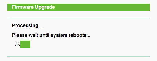
Ждём 5 минут…
Не трогайте и не отключайте роутер!
После этого роутер перезагрузится и адресом по умолчанию будет 192.168.1.1
Прошивка установлена.
Если уже стоит какая-то OpenWrt
Заходим на роутер и вводим следующие команды…
Переходим в папку /tmp:
cd /tmpСкачиваем прошивку:
wget http://istarik.ru/packages/mr3020.bin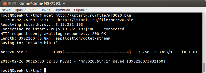
Прошиваем:
mtd -r write mr3020.bin firmwareНичего не трогаем
и ждём появления сообщения Rebooting …
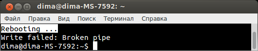
После этого ждём ещё минуту…
Прошивка установлена.
Шаг второй — установка пароля и подключение по SSH
По умолчанию в OpenWrt отключён защищённый протокол SSH и включён открытый протокол Telnet, это сделано из-за того, что не установлен пароль Администратора (root). Чтобы это изменить надо установить пароль.
Для пользователей Win
Пользователи Linux и Mac могут перейти ниже.
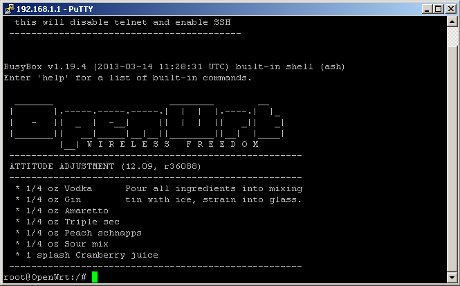
Запускаем ранее скачаную программу Putty:

Вводим адрес (192.168.1.1), выбираем протокол Telnet и нажимаем кнопку Open.
Появится консоль с приглашением ввода команд. Теперь мы «сидим на роутере».
1. Устанавливаем пароль администратора (root), для этого вводим команду passwd:
passwd
Нажимаем Enter.
Будет предложено ввести новый пароль для root, придумываем и записываем на бумажку!
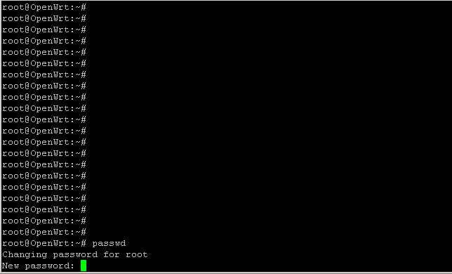
Вводим и нажимаем Enter. Внимание! Символы отображаться не будут!
Bad password:
Если Вы введёте слишком простой пароль, то роутер предупредит об этом:
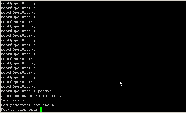
Если надёжность пароля не критична, то просто продолжайте, если критична, то нажмите два раза Enter, вернитесь к пункту 1 и придумайте пароль посложнее.
2. Роутер попросит повторить пароль:
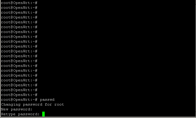
Вводим и нажимаем Enter. Внимание! Символы отображаться не будут!
Если всё прошло удачно, роутер ответит:
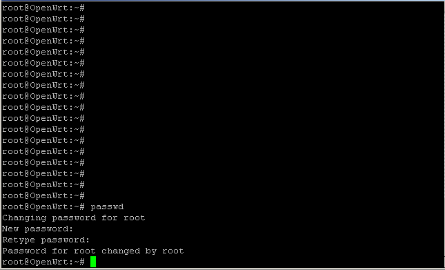
Перегрузите роутер командой reboot
rebootПосле этих манипуляций отключится протокол Telnet и заработает SSH.
Закрываем Putty и запускаем заново:
Вводим адрес (192.168.1.1), выбираем протокол SSH и нажимаем кнопку Open.
При первом соединении появится окно подтверждения соединения с незнакомым хостом.
Просто ответе Да.
Появится приглашение ввести логин:
Введите root и нажмите Enter.
Появится приглашение ввести пароль:
Введите пароль и нажмите Enter. Внимание! Символы отображаться не будут!
Получится вот так:
Всё, пароль установлен и ssh работает.
Для Linux и Mac
Открываем Терминал и пишем:
telnet 192.168.1.11. Вводим команду passwd:
passwdБудет предложено ввести новый пароль для root, придумываем и записываем на бумажку!
Changing password for root
New password:
Вводим и нажимаем Enter. Внимание! Символы отображаться не будут!
Bad password:
Если Вы ввёдёте слишком простой пароль, то роутер предупредит об этом:
Bad password: too weak
Если надёжность пароля не критична, то просто продолжайте, если нет, то нажмите два раза Enter, венитесь к пункту 1 и придумайте пароль посложнее.
2. Роутер попросит повторить пароль:
Retype password:Вводим и нажимаем Enter. Внимание! Символы отображаться не будут!
Если всё прошло удачно, роутер ответит:
Password for root changed by rootПерегрузите роутер командой reboot
rebootПосле этих манипуляций отключится протокол Telnet и заработает SSH.
Закройте Терминал и откройте новый.
Введите:
ssh root@192.168.1.1На вопрос «согласны ли Вы соединица с неизвестным хостом», напишите «yes» и нажмите Enter.
Введите пароль и нажмите Enter.
Всё, пароль установлен и ssh работает.
Шаг третий — настройка сети
Если MR3020 будет подключаться к другому (основному) роутеру, который подключён к интернету, тогда предполагается что он имеет адрес 192.168.1.1 и раздаёт адреса в диапазоне 192.168.1.2 — 254.
Если у Вас другая подсеть, то делайте всё что написано ниже, с учётом Вашего адресного пространства.
Действия одинаковы для всех операционных систем (Win, Linux, Mac).
Нужно отредактировать файл /etc/config/network
Заходим на роутер по ssh. (см. выше)
Вводим команду:
vi /etc/config/network
Текстовый редактор vi довольно-таки своеобразный инструмент.
Редактируем файл в соответствии с примером, для этого нажимаем символ «i» и вносим изменения:
config interface 'lan'
        option ifname 'eth0'
        option type 'bridge'
        option proto 'static'
        option netmask '255.255.255.0'
        option ipaddr '192.168.1.39'
        option dns '8.8.8.8'
        option gateway '192.168.1.1'
Нажимаем Esc.
Вводим последовательно символы :wq (: w-сохранить q-выйти)
Нажимаем Enter.
Файл отредактирован.
То же самое проделаем с файлом /etc/config/wireless
Вводим команду:
vi /etc/config/wireless
Вносим изменения «i«
config wifi-device 'radio0'
        option type 'mac80211'
        option channel '11'
        option macaddr '64:66:b3:94:0a:da' # оставьте свой
        list ht_capab 'SHORT-GI-20'
        list ht_capab 'SHORT-GI-40'
        list ht_capab 'RX-STBC1'
        list ht_capab 'DSSS_CCK-40'
        option txpower '27'
        option country 'US'

config wifi-iface
        option device 'radio0'
        option network 'lan'
        option mode 'ap'
        option ssid 'OpenWrt' #название точки
        option encryption 'psk2'
        option key '1234qwer' #пароль (не меньше 8-ми символов)
Esc > :wq > Enter
Перегружаемся:
rebootЕсли сеть строится через другой роутер, тогда выключаем MR3020 и переподключаем его и компьютер к основному роутеру.
Подключаемся вновь по ssh и вводим команду:
ping ya.ru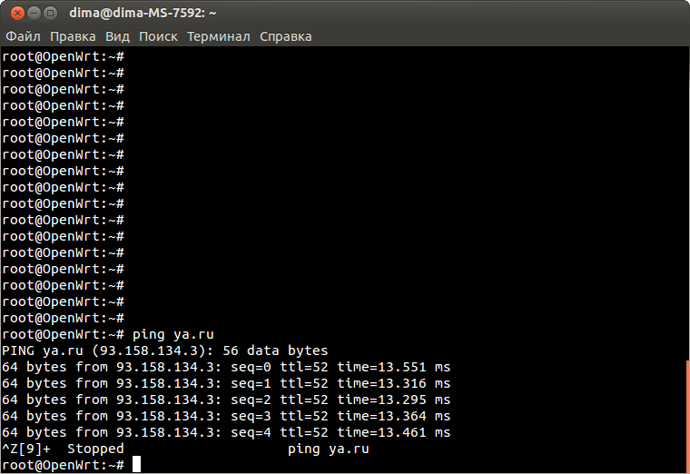
Если ping есть, то интернет настроен, нажмите Ctrl + z для выхода.
Если нет, то проверяем настройки файла /etc/config/network
Теперь надо поменять адрес репозитория в файле /etc/opkg.conf
vi /etc/opkg.confРедактируем в соответствии с примером:
src/gz attitude_adjustment http://istarik.ru/packages/mr3020/packages/
dest root /
dest ram /tmp
lists_dir ext /var/opkg-lists
option overlay_root /overlay
Первую строчку удалям и вместо неё вписываем указанную.
подсказка vi
Нажимаем символ «i«.
Вносим изменения.
Нажимаем Esc.
Вводим последовательно символы :wq (: w-сохранить q-выйти)
Нажимаем Enter.
Файл отредактирован.
Вводим команду для обновления репозитория:
opkg updateОтвет должен быть такой:
Downloading http://istarik.ru/packages/mr3020/packages/Packages.gz.
Updated list of available packages in /var/opkg-lists/...
Если вернётся ошибка, то проверьте файл /etc/opkg.conf
Шаг четвёртый — перенос системы на флешку
Утановим необходимые пакеты:
opkg updateopkg install kmod-usb-core kmod-usb-storage kmod-fs-ext4 kmod-scsi-core block-mount e2fsprogs fdisk kmod-usb-uhci kmod-usb-ohciПосле установки вводим по очереди две команды:
insmod uhciinsmod usb-ohciВставляем флешку.
Создадим на флешке раздел.
Вводим команду:
fdisk -lФлешка скорее всего определится как sda
Disk /dev/sda: 4009 MB, 4009754624 bytes
...
Вводим команду:
fdisk /dev/sda
Удаляем все разделы на флешке.
Жмём d и Enter пока не появится:
No partition is defined yet!
Создаем новый раздел.
Жмём n и Enter
Указываем его как первичный.
Жмём p и Enter
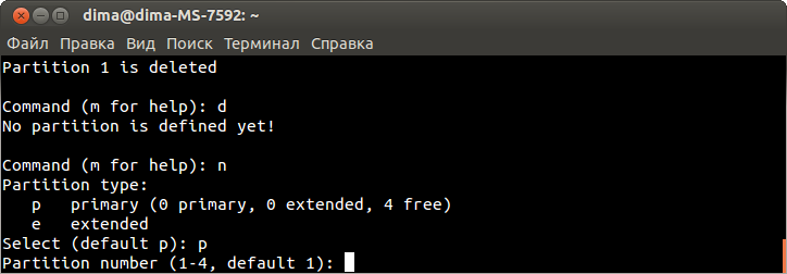
Жмём Enter
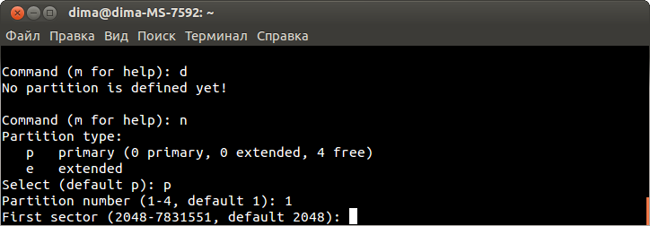
Жмём Enter
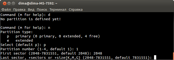
Жмём Enter
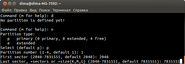
Готово
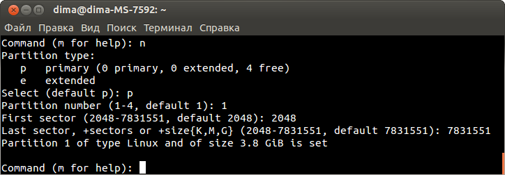
Сохраняем изменения:
Жмём w и Enter
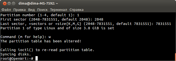
Всё окей…
Раздел создан и его надо отформатировать: Потребуется некоторое время.
mkfs.ext4 /dev/sda1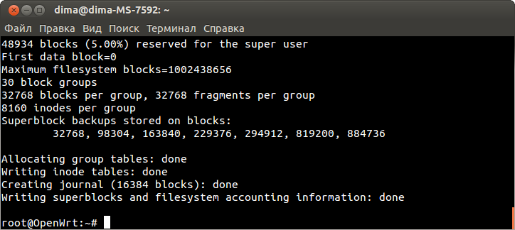
Готово.
Содаём папку /mnt/usb, монтируем туда флешку и переносим систему:
mkdir -p /mnt/usbmount -t ext4 /dev/sda1 /mnt/usb -o rw,synctar -C /overlay -cvf - . | tar -C /mnt/usb -xvf -Теперь нужно отредактировать файл /etc/config/fstab
vi /etc/config/fstabСекция mount
config 'mount'
option target /overlay
option device /dev/sda1
option fstype ext4
option options rw,sync
option enabled 1
option enabled_fsck 0
подсказка vi
Нажимаем символ «i«.
Вносим изменения.
Нажимаем Esc.
Вводим последовательно символы :wq (: w-сохранить q-выйти)
Нажимаем Enter.
Файл отредактирован.
Сохраняем изменения и перегружаем роутер.
rebootЗаходим и проверяем:
df -hВ ответ должно быть что-то типа:
/dev/sda1 3.7G 65.8M 3.6G 2% /overlay
overlayfs:/overlay 3.7G 65.8M 3.6G 2% /
Ну вот, теперь места у нас полно, можно ставить что угодно.
Установим кодировки и Midnight Commander:
opkg updateopkg install kmod-nls-cp1251 kmod-nls-koi8r kmod-nls-utf8 kmod-nls-cp866 kmod-nls-cp437 opkg install mc
Web-интерфейс LuCI:
opkg install luci luci-i18n-russian luci-proto-3g luci-proto-ppp ppp-mod-pptp ppp-mod-pppoaДобавляем Luci в автозагрузку и стартуем:
/etc/init.d/uhttpd enable/etc/init.d/uhttpd start192.168.1.39
На этом всё
Здесь описана установка сервера Lighttpd и PHP.

Статья про то как прошить и настроить роутер TP-Link MR3020[/URL] или TL-WR703N для использования его в своих проектах.
Популярный проект WiFi робот
Так же wr703n и MR3020 можно прошить прошивкой CyberWrt, данная прошивка понравится тем кто не хочет использовать дополнительный софт(PUTTY, WinCSP и др.)
В этой прошивке встроен веб интерфейс , к роутеру можно подключатся через любой веб браузер,
Доступны все возможные модули благодаря которым Вы в считанные секунды, можете превратить свой роутер в
Видеорегистратор, Веб радио, Часы, Робота, WiFi контроллер и пр. и при этом не почувствуете что работаете с линуксом
Цитата:
Уважаемые пользователи. на прошивке Attitude Adjustment 12.09 есть баг или фича (скорее конечно фича) — при монтировании разделов созданных в OS Windows — необходимо чтобы они были Primary. В противном случае, если раздел будет Logical (даже есть он ext2-3-4) при попытке монтирования ваша железка зависнет и перезагрузится.

Характеристики роутера TP-Link MR3020:
процессор Atheros AR7240 частотой 400 МГц
SoC: Atheros AR9330 Rev 1
32 Мб ram
4 Мб флэш-памяти
USB-2.0 Host
Wi-Fi 802.11 b/g/n 150Mbps
Ethernet-порт 100MBit
UART (на плате)
Питание осуществляется через мини-USB (+5В)
Максимальный ток с включенным Wi-Fi 150мА или 100мА без него.
Размер печатной платы: 5,7см х 5,7см
Размер роутера: 6,7см х 7.4cm х 2.2cm
1. Прошивка
Вместо заводской прошивки, зальем на него OpenWRT.
Сначала скачиваем новую прошивку от 21.09.12 (r33482) с этого форума. Подключаем роутер к компьютеру LAN кабелем (адрес по-умолчанию: 192.168.0.254), логин/пароль: admin/admin. Заходим через браузер в системные настройки, выбираем заранее скаченый файл прошивки, нажимаем кнопку обновить и ждем пока зальется. Во время прошивки не трогайте роутер и не отключайте его питание, иначе получите танцы с бубном или убитый роутер. После прошивки роутер уйдет автоматически в ребут. Теперь роутер получил адрес 192.168.1.1. Подключаемся к нему телнетом, я использовал Putty и получаем окно терминала
2. Начальная настройка сети
Открываем фаил network текстовом редакторе vi и пропишем в нем свои сетевые настройки:
root@OpenWrt:~# vi /etc/config/network
Настройки Секции config interface ‘lan’ должны выглядеть так:
Код:
config interface 'lan'
option ifname 'eth0'
option type 'bridge'
option proto 'static'
option ipaddr '192.168.1.99'    # новый IP роутера MR3020
option netmask '255.255.255.0'  # маска
option gateway '192.168.1.1'    # шлюз к которому будет подключаться mr3020
list dns '192.168.1.1'          # DNS1 сервер (головной роутер)
list dns '8.8.8.8'              # DNS2 сервер
Здесь подразумевается, что головной роутер имеет адрес: 192.168.1.1
Если у вас другая подсеть необходимо сменить сетевые адреса на вашу подсеть.
Для дальнейшей настройки роутера mr3020 необходимо его подключить по Ethernet к головному роутеру или ADSL модему получающему интернет.
Схема подключения
Еще нужно добавить строку в /etc/sysupgrade.conf для предотвращения перезаписи конфигов после ребута.
root@OpenWrt:~#echo «/etc/config/» >> /etc/sysupgrade.conf
Выполняем Reboot.
Ждем перезагрузки и проверяем подключение к Интернету:
root@OpenWrt:~#ping cyber-place.ru
Если пингуется:
PING cyber-place.ru (5.9.57.134): 56 data bytes
64 bytes from 5.9.57.134: seq=0 ttl=252 time=52.902 ms
64 bytes from 5.9.57.134: seq=1 ttl=252 time=52.017 ms
64 bytes from 5.9.57.134: seq=2 ttl=252 time=52.137 ms
64 bytes from 5.9.57.134: seq=3 ttl=252 time=52.376 ms
64 bytes from 5.9.57.134: seq=4 ttl=252 time=52.128 ms
64 bytes from 5.9.57.134: seq=5 ttl=252 time=52.166 ms
Прерываем выполнение нажатием клавиш Ctrl^C
Здесь нужно быть внимательным! т.к. использовалась прошивка от 21.09.2012 r33482 (с этого форума) для установки пакетов нужно поменять источник репозитория тоже на эту-же версию.
Правим файл /etc/opkg.conf
комментируем 1-ю строчку и добавляем свою
Код:
#src/gz attitude_adjustment http://downloads.openwrt.org/snapshots/trunk/ar71xx/packages
src/gz attitude_adjustment http://cyber-place.ru/download/packages/
dest root /
dest ram /tmp
lists_dir ext /var/opkg-lists
option overlay_root /overlay
3. Подклчение внешней флэшки.
Казалось бы на этом все, но в своем распоряжении вы имеете очень маленький объем Flash памяти, всего 1.4 Мб, из которых свободно всего около 300 Кб! Этого не хватит даже LuCI установить. Выход есть, нужно подключить внешнюю USB флешку.
Для этого придется выполнить все что я написал ниже.
Начинаем установку пакетов программ!
Обновляем список пакетов и устанавливаем нужные нам пакеты:
root@OpenWrt:~# opkg update
root@OpenWrt:~# opkg install kmod-usb2
root@OpenWrt:~# insmod ehci-hcd
root@OpenWrt:~# opkg install kmod-usb-core kmod-usb-storage kmod-fs-ext4 kmod-scsi-core block-mount e2fsprogs fdisk
Посмотреть список установленных пакетов:
root@OpenWrt:~# opkg list-installed
…
…
kmod-scsi-core — 3.3.8-1
kmod-usb-core — 3.3.8-1
kmod-usb-ohci — 3.3.8-1
kmod-usb-storage — 3.3.8-1
kmod-usb-uhci — 3.3.8-1
kmod-usb2 — 3.3.8-1
kmod-wdt-ath79 — 3.3.8-1
…
…
Смотрим как флешка определась системой:
root@OpenWrt:~# fdisk -l
у меня USB Flash-диск определился как sda
Disk /dev/sda: 1018 MB, 1018691584 bytes
9 heads, 56 sectors/track, 3947 cylinders, total 1989632 sectors
Units = sectors of 1 * 512 = 512 bytes
Sector size (logical/physical): 512 bytes / 512 bytes
I/O size (minimum/optimal): 512 bytes / 512 bytes
Disk identifier: 0x0004862f
Device Boot Start End Blocks Id System
/dev/sda1 2048 1989631 993792 83 Linux
Сначала создаем на USB Flash раздел:
root@OpenWrt:~# fdisk /dev/sda
Выполняем следующие команды:
Command (m for help): d
Partition number (1-4): 1
Command (m for help): d
Partition number (1-4): 2
Command (m for help): d
Partition number (1-4): 3
Command (m for help): d
No partition is defined yet!
Создаем раздел:
Command (m for help): n
Command action
e extended
p primary partition (1-4)
p
Partition number (1-4): 1
First cylinder (27-122, default 27):
Using default value 27
Last cylinder or +size or +sizeM or +sizeK (27-122, default 122):
Using default value 122
Смотрим, что получилось:
Command (m for help): p
Disk /dev/sda: 1018 MB, 1018691584 bytes
7 heads, 8 sectors/track, 35529 cylinders, total 1989632 sectors
Units = sectors of 1 * 512 = 512 bytes
Sector size (logical/physical): 512 bytes / 512 bytes
I/O size (minimum/optimal): 512 bytes / 512 bytes
Disk identifier: 0x0004862f
Device Boot Start End Blocks Id System
/dev/sda1 * 2048 1989631 993792 83 Linux
Command (m for help): a
Partition number (1-4): 1
Выходим:
Command (m for help): w
The partition table has been altered!
Calling ioctl() to re-read partition table.
Syncing disks.
Раздел создан, форматируем его:
root@OpenWrt:~# mkfs.ext4 /dev/sda1
mke2fs 1.42.4 (12-June-2012)
Filesystem label=
OS type: Linux
Block size=4096 (log=2)
Fragment size=4096 (log=2)
Stride=0 blocks, Stripe width=0 blocks
62208 inodes, 248448 blocks
12422 blocks (5.00%) reserved for the super user
First data block=0
Maximum filesystem blocks=255852544
8 block groups
32768 blocks per group, 32768 fragments per group
7776 inodes per group
Superblock backups stored on blocks:
32768, 98304, 163840, 229376
Allocating group tables: done
Writing inode tables: done
Creating journal (4096 blocks): done
Writing superblocks and filesystem accounting information: done
Монтируем новый диск и копируем на него все необходимое:
root@OpenWrt:~# mkdir -p /mnt/usb
root@OpenWrt:~# mount -t ext4 /dev/sda1 /mnt/usb -o rw,sync
root@OpenWrt:~# tar -C /overlay -cvf — . | tar -C /mnt/usb -xvf —
Правим фаил /etc/config/fstab:
root@OpenWrt:~# vi /etc/config/fstab
Нам нужно отредактировать секцию config ‘mount’:
config ‘mount’
option target /overlay
option device /dev/sda1
option fstype ext4
option options rw,sync
option enabled 1
option enabled_fsck 0
Сохраняем, перезагружаемся, проверяем:
root@OpenWrt:~# df -h
Filesystem Size Used Available Use% Mounted on
rootfs 968.0M 51.9M 867.6M 6% /
/dev/root 1.5M 1.5M 0 100% /rom
tmpfs 14.2M 72.0K 14.2M 0% /tmp
tmpfs 512.0K 0 512.0K 0% /dev
/dev/sda1 968.0M 51.9M 867.6M 6% /overlay
overlayfs:/overlay 968.0M 51.9M 867.6M 6% /
Отлично!!! У нас теперь много свободного пространства, для установки модулей и утилит.
4. Последние шрихи.
Устанавливаем поддержку кодировок
opkg update
opkg install kmod-nls-cp1251 kmod-nls-koi8r kmod-nls-utf8 kmod-nls-cp866 kmod-nls-cp437
Детальное описание всего что устанавливалось на роутер TP-LINK
Примечание
Так как при работе с роутером необходимо постоянно что-то редактировать и изменять, очень удобно (вместо встроенного vi) работать используя WinSCP — это графический клиент SFTP (SSH File Transfer Protocol) для Windows с открытым исходным кодом. Он также поддерживает протокол SCP (Secure Copy Protocol). Предназначен для защищённого копирования файлов между компьютером и серверами, поддерживающими эти протоколы. Программа имеет встроенный редактор (но можно подключить и внешний). Есть также руссификатор программы.
Для работы по защищенному протоколу SSH, SCP необходимо задать пароль для пользователя root. Для этого необходимо в консоле дать команду: passwd и ввести ваш новый пароль (ввод не видим), затем повторить еще раз.
Это также позволит работать с Putty используя SSH протокол (22 порт).
Более детально можно прочитать здесь
Search code, repositories, users, issues, pull requests…
Provide feedback
Saved searches
Use saved searches to filter your results more quickly
Sign up