Native VLAN — некоторое количество информации о данном виде VLAN. Что это такое, для чего нужна Native VLAN и откуда она взялась.
Все слышали краем уха про Native VLAN (далее NV), расскажу подробнее что это такое (на примере CISCO). Те кто знает про NV «от и до» — вам жму руку и обязуюсь выложить что-то интересненькое и для вас.
Что известно о Native VLAN?
В переводе с английского native — родной, естественный, встроенный:
- Это понятие привязано к транковому каналу передачи данных и без него не используется;
- Если взять коммутатор CISCO «из коробки», то на нём присутствует только одна VLAN — VLAN1 (всякая устаревшая экзотика типа VLANs 1002 — 1005 не в счёт), в этой же VLAN1 изначально находятся все порты;

- Далее, если настроить на коммутаторе ещё несколько VLANs и настроить транковые порты, то для всех транковых портов по умолчанию будет NV=VLAN1:
Switch(config)#vlan 10
Switch(config-vlan)#vlan 11
Switch(config-vlan)#vlan 12
Switch(config)#interface gigabitEthernet 0/0
Switch(config-if)#switchport trunk encapsulation dot1q
Switch(config-if)#switchport mode trunk
Switch(config-if)#end
Switch#show interfaces trunk

Port   Mode Encapsulation  Status     Native vlan
Gi0/0  on   802.1q         trunking   1
- На одном коммутаторе у разных транковых портов может быть разная NV. Это нормально и часто используется. Меняется NV для танкового порта командой:
Switch(config)#interface gigabitEthernet 0/0
Switch(config-if)#switchport trunk native vlan 12
- Любой кадр без тега, поступивший из транка на коммутатор, пересылается в NV;
- Для любого транкового порта VLAN без тега всегда одна;
Дополнительно: любой порт в режиме доступа принадлежит только одной VLAN. Тут есть исключение: Asymmetric VLAN. Эту технологию использует D-Link. Вещь специфическая, область применения — SOHO. Кто хочет сломать мозги, подробнее тут. Ради справедливости надо сказать, что CISCO тоже применяет понятие Asymmetric VLAN для коммутаторов. Только используется совсем в другом контексте. Подробный гайдлайн легко ищется через поисковик.
- NV с обоих сторон транка, то есть на разных коммутаторах, должна быть одинаковой, иначе в консоль выдаётся предупреждающее сообщение;
%CDP-4-NATIVE_VLAN_MISMATCH: Native VLAN mismatch discovered on GigabitEthernet1/1 (169), with S2 GigabitEthernet1/1 (1)
Почему одинаковой? Любой кадр без тега, поступивший из транка на коммутатор, пересылается в NV. Допустим 2 коммутатора S1 и S2, у S1 NV=VLAN1, у S2 NV=VLAN10. Тогда кадры из VLAN1 с коммутатора S1 будут попадать во VLAN10 на S2 и наоборот. Это ошибка в конфигурации и нарушение безопасности.
- Кадры, пересылаемые через транк для NV не тегируются;
Это можно изменить глобальной настройкой. Пользоваться этой настройкой крайне не рекомендуется. Да и честно даже не знаю в каком случае это может пригодиться. Возможно разве при траблшутинге подключения коммутатора CISCO к какому-то специфическому оборудованию.

- Если транковый порт получает тегированный кадр с таким же идентификатором как у NV, то он отбрасывает кадр;
If an 802.1Q trunk port receives a tagged frame with the VLAN ID the same as the native VLAN, it drops the frame.

CCNA R&S: Routing and Switching Essentials
Тут возникает вопрос: а как тогда вообще возможна атака с двойным тегированием? Подробнее далее.
Для чего же была придумана Native VLAN?
По идее через транк должен ходить только тегированный трафик, но что делать коммутатору, если из транка приходят кадры без тега? Тут два варианта:
- Отбросить такой трафик;
- Обработать такой трафик
Чтобы была возможность обрабатывать трафик без тега, поступающий из транкового канала и отсылать в транк трафик без тега, была придумана Native VLAN:
Native VLANs are defined in the IEEE 802.1Q specification to maintain backward compatibility with untagged traffic common to legacy LAN scenarios. A native VLAN serves as a common identifier on opposite ends of a trunk link.

CCNA R&S: Routing and Switching Essentials
Отсюда интересное явление: со стороны коммутатора транковый порт, к нему подключен PC. Трафик будет ходить? Будет:
- Приходит нетегированный (естественно) трафик от PC, коммутатор отправляет этот трафик в NV;
- Приходят данные со стороны коммутатора на порт для NV, данные будут переданы без тега и PC сможет их обработать.
На этом построено подключение компьютера через IP-телефон. К телефону от коммутатора прокинут транк с двумя VLANs, допустим, NV=VLAN3 и ещё VLAN5. Тогда телефон работает через VLAN5 с тегом, а PC через VLAN3 без тега (подробнее: //ciscomaster.ru/node/89).
Вот собственно и всё про данное понятие. Далее будут уже более специфичные особенности NV.
Несовпадение NV на концах транка
Что говорит по этому поводу сама CISCO:
Remember that the native VLAN must match on both sides of the trunk link for 802.1Q; otherwise the link will not work. If there is a native VLAN mismatch, Spanning Tree Protocol (STP) places the port in a port VLAN ID (PVID) inconsistent state and will not forward on the link.
Проверим эту ситуацию. Накидал лабу в EVE-NG:

Задал всем трём VPC адресацию 192.168.1.0/24. По идее если транк работоспособен, VPC1 должен пинговать VPC3, так как они в одной VLAN10. И VPC1 должен пинговать VPC2 через NV.
Проверяем: VPC1 пингует VPC2. Проверяем дальше: VPC1 не пингует VPC3. Немного подумав становится понятно, что при пинге VPC3, VPC1 отправит пакеты ARP и кадры содержащие эти пакты будут переданы без тега в транке, а кадры без тега на S2 перенаправляются в NV, то есть в VLAN20. И VPC2 эти ARP увидит, а VPC3 соответственно нет.
Что касается STP, попробовал все три режима MST, PVST+, Rapid PVST+ и каждый раз порты Gi0/0 были в режиме передачи (FWD) для всех VLANs.
Итого: при несовпадении NV транк работает, некорректно но работает. Вот такое расхождение с теорией. Хотя надо учитывать что пробовалось всё не на реальном железе, а на эмуляторе и возможно зависит от версии IOS.
NV на роутере
А может присутствовать NV на роутере? Конечно. Используется это в не очень хорошей схеме Router-on-a-Stick (роутер на палочке).
Схемы применения Router-on-a-Stick
Типовая, в этой схеме роутер связан с коммутатором транковым каналом, на роутере заводятся сабинтерфейсы (sub-interface) или есть русское слово подынтерфейс, но мне оно не нравится. Итак, один сабинтерфейс для одной VLAN. На каждом сабинтерфейсе настраивается IP адрес. Этот адрес используется как шлюз по умолчанию для данной VLAN. Таким образом достигается маршрутизация между VLANs посредством роутера. Недостатки такого метода:
- Слабая масштабируемость — максимум 50 VLANs для такого метода;
- При маршрутизации пакет проходит 2 раза по транковому каналу: первый раз от коммутатора к роутеру в составе кадра для исходной VLAN и второй раз от роутера к коммутатору в составе кадра для VLAN назначения. Таким образом, этот линк потенциальное узкое место при интенсивном трафике между VLANs.
А если данный линк 100 мегабитный, то это просто мрак. CISCO рекомендует настраивать маршрутизацию между VLANs на коммутаторе 3 уровня. В продакшене перевод схемы Router-on-a-Stick со 100Mbit линком в схему маршрутизации на коммутаторе, давал сокращение времени архивации сервера на сервер в другой VLAN в 3 с лишним раза.
Для VRF, когда между двумя роутерами один интерфейс и его надо поделить на несколько VRF, чтобы форвардить через каждый VRF свои VLANs. Это не совсем Router-on-a-Stick в привычном понимании, но принцип тот же (для R1 из рисунка):
interface GigabitEthernet0/0/0.1
  encapsulation dot1Q 10
  ip vrf forwarding Special-Users
  ip address 10.0.12.1 255.255.255.0
  ipv6 address 2001:db8:acad:12::1/64
  ipv6 address fe80::1:1 link-local
!
interface GigabitEthernet0/0/0.2
 encapsulation dot1Q 12
 ip vrf forwarding General-Users
 ip address 10.0.12.1 255.255.255.0
 ipv6 address 2001:db8:acad:12::1/64
 ipv6 address fe80::1:1 link-local

Экзотические, в интернете наткнулся на интересную схему Router-on-a-Stick. Можно так сделать? Можно, работать будет. А нужно? Нет, не нужно. У меня даже больше вопросы не по безопасности, хотя данная схема полностью противоречит архитектуре иерархической сети, а то что оба провайдера висят на одном линке. Логичнее было бы каждого провайдера подключить к отдельному интерфейсу роутера напрямую и тогда Router-on-a-Stick просто становится не нужен.
Когда такую схему подключения полезно было бы задействовать? В ситуации когда у роутера остался только 1 рабочий порт, нет другого роутера и нет модулей расширения HWIC. Как временное решение.
Настройка NV на роутере
Возвращаемся к настройке Router-on-a-Stick, создаём логические сабинтерфейсы на роутере для примера выше, когда на коммутаторе настраивались VLANs 10,11,12:
Router(config)#interface GigabitEthernet 0/0
Router(config-if)#no shutdown
Router(config-if)#interface GigabitEthernet 0/0.10
Router(config-subif)#encapsulation dot1Q 10
Router(config-subif)#ip address 192.168.10.1 255.255.255.0
Router(config-if)#interface GigabitEthernet 0/0.11
Router(config-subif)#encapsulation dot1Q 11
Router(config-subif)#ip address 192.168.11.1 255.255.255.0
Router(config-if)#interface GigabitEthernet 0/0.12
Router(config-subif)#encapsulation dot1Q 12
Router(config-subif)#ip address 192.168.12.1 255.255.255.0
Сабинтерфейсы включать не надо. Они будут включены автоматически, когда включён GigabitEthernet0/0. Теперь смотрим информацию о VLANs:
Router#show vlans

Virtual LAN ID: 1 (IEEE 802.1Q Encapsulation)

vLAN Trunk Interface: GigabitEthernet0/0

This is configured as native Vlan for the following interface(s) :
GigabitEthernet0/0 Native-vlan Tx-type: Untagged

...
По умолчанию NV всё та же VLAN1. Теперь сменим её:
Router(config-if)#interface GigabitEthernet 0/0.12
Router(config-subif)#encapsulation dot1Q 12 native
Снова смотрим информацию о VLANs:
Router#show vlans

Virtual LAN ID: 1 (IEEE 802.1Q Encapsulation)

vLAN Trunk Interface: GigabitEthernet0/0

...

Virtual LAN ID: 12 (IEEE 802.1Q Encapsulation)

vLAN Trunk Interface: GigabitEthernet0/0.12

This is configured as native Vlan for the following interface(s) :
GigabitEthernet0/0 Native-vlan Tx-type: Untagged
Что делать если роутер не CISCO?
Если устройство не CISCO и у него нет возможности явной настройки NV на сабинтерфейсе, то NV нужно размещать на основном интерфейсе.
Пример. На коммутаторе NV=VLAN1, на роутере сабинтерфейс для VLAN1 не создаём. Почему? Если его создать, то трафик со стороны роутера будет тегироваться, коммутатор откинет тегированный трафик для NV. То есть IP адрес для NV (VLAN1) должен висеть на самом interface GigabitEthernet 0/0 роутера для примера сверху. Немного странная схема, но она работает.
Проверено на Dionis NX, ASA 55X0 (ASA хоть и CISCO, но не роутер и многое тут по-другому).
Немного о теге
Для того чтобы прикладывать тег, размер кадра пришлось увеличивать на 4 байта. Размер нетегированного кадра от 64 до 1518 байт, тегированного от 68 до 1522.

- TPID — устанавливается значение 0x8100 для идентификации кадра в качестве кадра с разметкой IEEE 802.1Q;
- Priority — поле указывается уровень приоритетности кадра, который можно использовать для приоритизации трафика. Полем может задаваться 8 уровней (от 0 до 7);
- CFI — раньше был CFI, для отличия кадра FDDI, Token Ring от кадра Etnernet. Поскольку давно никаких FDDI нет, а поле пропадает, то оно было перепрофилировано в DEI. DEI указывает может ли кадр быть отброшен в случае затора на интерфейсе;
- VID — уникальным образом идентифицирует VLAN, которой принадлежит кадр. В этом поле могут содержаться значения от 0 до 4095.
Процесс тегирования
У меня с коллегой по работе один раз вышел спор: внутри коммутатора кадр перемещается с тегом или без? Однозначного ответа тут нет. Постараюсь пояснить почему.
Нет единого стандарта как делать коммутаторы. Логика работы и начинка коммутатора различается от вендора к вендору. Вспомнить хотя бы D-Link и его Asymmetric VLAN.
Стандартом является только транк 802.1Q: внутри транка кадры передаются с тегом, кроме кадров NV. Это обеспечивает совместимость между коммутаторами разных вендоров.
Если брать коммутаторы CISCO, то по приходу кадра на порт коммутатора, управляющий портом ASIC (Application Specific Integrated Circuit) навесит на кадр дополнительный служебный заголовок. Этот заголовок называется shim header и существует только внутри коммутатора. В этом заголовке точно есть информация о VLAN, так коммутатор различает кадры из разных VLANs.
А что насчёт тега 802.1Q? Если размышлять в рамках CCNA R&S, то:
The standard Ethernet frame header does not contain information about the VLAN to which the frame belongs; thus, when Ethernet frames are placed on a trunk, information about the VLANs to which they belong must be added. This process, called tagging, is accomplished by using the IEEE 802.1Q header, specified in the IEEE 802.1Q standard.

CCNA R&S: Routing and Switching Essentials
Поэтому обобщённо-упрощённая рабочая версия процесса тегирования при отсутствии CoS и сабинтерфейсов такая:
- Кадр приходит на порт доступа коммутатора, поверх к нему цепляется служебный заголовок, определяющий в том числе к какой VLAN кадр принадлежит;
- Затем кадр попадает на транковый порт для передачи, внутрь его заголовка L2 помещается тег 802.1Q, а служебный заголовок снимается;
- По приходу кадра на транковый порт принимающего коммутатора тег 802.1Q отрывается и снова навешивается служебный заголовок.
Если же используется CoS (маркировка трафика на втором уровне, при этом инфа записывается в поле Pri, соответственно без тега не обойтись) или сабинтерфейсы то, тег 802.1Q вставляется в заголовок уже по приходу кадра на порт доступа.
Если я не прав — поправьте, вопрос открытый.
Рекомендации CISCO
Что рекомендует CISCO:
- Менять NV с дефолтного VLAN1;
- Не использовать NV для передачи пользовательского трафика.
Естественно все забивают забывают про эти рекомендации. Если NV транков используется где-то для пользовательского трафика, то может проводиться атака с двойным тегированием.
Атака с двойным тегированием
Суть этой атаки, как объясняет сама CISCO:
Допустим у нас для транков NV = VLAN10. И эта же VLAN10 используется для пользовательских компьютеров. А VLAN20 используется для серверов.
- С помощью специального софта зловред отправляет кадр с двумя тегами:

- Первый (внешний) тег для VLAN10, второй (внутренний) тег для VLAN20;
- Когда кадр придёт на коммутатор он срежет внешний тег. Наличие других тегов коммутатор не проверяет;
- После этого коммутатор разошлёт кадр через VLAN10, так кадр попадёт на транк между коммутаторами;
- Поскольку NV = VLAN10, то при отправке кадра через транк коммутатор не будет навешивать новый тег;
- Кадр поступает на второй коммутатор, там тег для VLAN20 срезается и кадр рассылается через VLAN20.
Предлагаю самостоятельно найти несостыковки с теорией. И возможно объяснить их. Пытался много раз, так и не смог объяснить.
Кроме этого есть специальная технология двойного тегирования Q-in-Q (или dot1q tunneling ). С ней работать не приходилось, поэтому подробнее не расскажу. Но надо знать что двойной тег в общем-то возможен, хотя конечно зависит от реализации вендором.
Когда удобно менять Native VLAN
Хоть NV и не рекомендуется использовать для пользовательского трафика, иногда это бывает весьма удобно.
Пример. Коллега из серверного отдела попросил меня настроить коммутатор. На коммутаторе будут только севера. Все сервера находятся в серверной VLAN. Однако неизвестно в какие порты будут подключены серверы виртуализации. Подключать будет сотрудник первой линии, максимум чего можно ждать, что он привинтит коммутатор, подаст питание, подключит патч-корды. A нужно чтобы 100% всё заработало сразу.
Делаем все «пользовательские» порты коммутатора транками. В качестве NV выбираем серверную VLAN:
- Обычные сервера с акцесными портами нормально заработают (описано выше почему);
- У серверов виртуализации настроен транк. Сам сервер виртуализации будет работать через NV транка без тега, а его виртуальные машины из разных VLANs через транк с тегом. Профит.
Никого не призываю так делать и возможно потом вылезут проблемы (так и получилось), но когда лимит времени и нужен результат сразу, очень даже хорошо.
Проблема из продакшена
Чтобы не ограничиваться сухой теорий, небольшой пример из продакшена. Он заставил меня поломать голову. Пример лишь косвенно связан с Native VLAN. С другой стороны роскошь, что хоть такой пример удалось подобрать.
Итак, есть 10 коммутаторов CISCO, 4 коммутатора Qtech и 1 D-Link, подключённых по топологии звезда. «Звезда смерти»: если посмотреть Иерархическую модель сети CISCO, то никакой звезды в продакшене быть не должно.
У каждого периферийного свича 1 транк до центрального CISCO 3750X. Конфигурации однотипные, центральный свич настроен корневым мостом STP. На CISCO используется Rapid PVST+ (1 дерево RSTP на каждую VLAN), на остальных RSTP (1 дерево RSTP на все VLANs).
При этом 4 периферийных Qtech также считают себя корневыми. Поскольку топология звезда, то для возникновения петли надо очень постараться и долгое время всё это так работало.
Самым правильным было бы изменить для всех коммутаторов протокол на MSTP. Но с другой стороны Rapid PVST+ и RSTP совместимы? Совместимы. Значит должно работать.
Разбираемся
Настройка приоритета STP и другие потуги именно с STP ничего не дают. Перекидываем аплинки к центральному коммутатору между одним из проблемных Qtech и нормально работающим D-Link, Qtech начинает «видеть» в разрезе STP корневой свич, D-Link перестаёт. Поэтому проблема, очевидно, не в марке Qtech.
Дальнейшее изучение показывает: проблемные свичи Qtech/D-Link не получают кадров BPDU. Далее обнаруживается, что для всех транков со стороны центрального свича не разрешена явным образом VLAN1. Она же является NV для всех транков. Добавление VLAN1 в список разрешённых сразу решает проблему.
При этом для периферийных коммутаторов CISCO никакой проблемы не было и нет.
Логика человека настраивавшего коммутаторы понятна. Нарезали VLANs, перевели туда все порты, во VLAN1 портов нет? Нет. Стало быть, зачем её разрешать на транке?
Постановка вопроса
Теперь нужно выяснить для D-Link и Qtech:
- Проблема в Native VLAN и Native VLAN должна быть разрешена в явном виде;
- Проблема во VLAN1 и VLAN1 должна быть разрешёна в явном виде.
Проверка №1
Начнём с D-Link:

Всё нормально, Root Port, Root Bridge. Убираем на центральном коммутаторе для транка на D-Link VLAN1 из списка разрешённых и ждём 20 секунд:

Коммутатор D-Link считает себя корневым.
Проверка №2
Теперь повторяем всё тоже самое с Qtech. Сначала VLAN1 разрешена в явном виде:

Всё гуд. Точно так же убираем на центральном свиче с транка на Qtech VLAN1 из разрешенных:

Количество полученных BPDU не меняется с этого момента. И коммутатор Qtech, рассчитав STP, считает себя корневым. Проблема актуальна.
Проверка №3
Теперь создаём VLAN 99, меняем NV с 1 на 99 с обоих сторон транка, удаляем VLAN 99 из разрешённых, а VLAN 1 наоборот добавляем в разрешённые и ещё раз проверяем. Если ситуация повторится, то данные STP для D-Link/Qtech привязаны к Native VLAN, нет — привязаны к VLAN 1.
Моя ставка была на Native VLAN, так как именно через неё должна передаваться служебная информация в случает CST, но я ошибся. Как оказалось после проверки — данные привязаны к VLAN1 и от NV не зависят. Скорее всего это особенности реализации технологии совместимости Rapid PVST+ и RSTP данными вендорами на данных моделях коммутаторов.
Откуда я вообще взял что именно через NV должна передаваться служебная информация? Для этого конкретного случая инфу нашёл:
Only a single instance of STP is used for all VLANs. If there are 500 VLANs, only 1 instance of STP will be running. This is called the Common Spanning Tree (CST) and operates over the trunk’s native VLAN.

CCNP Routing and Switching SWITCH 300-115 Official Cert Guide
Заключение
Первый вывод простой и очевидный: для лучшей совместимости не стоит делать «солянку» из коммутаторов разных вендоров. А если такая солянка уже есть, то не нужно использовать проприетарные протоколы на группе коммутаторов одного вендора. Наоборот, необходимо использовать открытые протоколы IEEE на всех коммутаторах сразу.
Вывод второй: работа Native Vlan, тегирование 802.1Q — не такие уж простые вещи, как может показаться на первый взгляд.
Материал из Xgu.ru
Перейти к: навигация, поиск
- Короткий URL: vlan/cisco
- Автор: Наташа Самойленко
< VLAN
На этой странице рассматривается процедура настройки VLAN в Cisco.
На странице VLAN в Cisco/Lab находятся лабораторные, которые можно сделать для того чтобы на практике попробовать настройки, которые описываются на этой странице. Лабораторные подготовлены в Packet Tracer, но аналогично могут быть выполнены и на реальном оборудовании.
Содержание
- 1 Настройка VLAN на коммутаторах Cisco под управлением IOS
- 1.1 Настройка access портов
- 1.2 Настройка транка (trunk)
- 1.2.1 Настройка статического транка
- 1.2.2 Динамическое создание транков (DTP)
- 1.2.3 Разрешённые VLAN’ы
- 1.2.4 Native VLAN
- 1.3 Настройка маршрутизации между VLAN
- 1.4 Перевод интерфейса в режим 3го уровня
- 1.5 Просмотр информации
- 1.6 Диапазоны VLAN
- 1.7 Пример настройки
- 1.7.1 Пример базовой настройки VLAN, без настройки маршрутизации
- 1.7.2 Пример конфигураций с настройкой маршрутизации между VLAN
- 2 Настройка VLAN на маршрутизаторах Cisco
- 2.1 Пример настройки
- 2.2 Настройка native VLAN
- 3 Примечания
[править] Настройка VLAN на коммутаторах Cisco под управлением IOS

![]()
Сеть с VLANами на коммутаторах Cisco
Терминология Cisco:
- access port — порт принадлежащий одному VLAN’у и передающий нетегированный трафик
- trunk port — порт передающий тегированный трафик одного или нескольких VLAN’ов
Коммутаторы Cisco ранее поддерживали два протокола 802.1Q и ISL. ISL — проприетарный протокол использующийся в оборудовании Cisco. ISL полностью инкапсулирует фрейм для передачи информации о принадлежности к VLAN’у.
В современных моделях коммутаторов Cisco ISL не поддерживается.
Создание VLAN’а с идентификатором 2 и задание имени для него:
sw1(config)# vlan 2
sw1(config-vlan)# name test
Удаление VLAN’а с идентификатором 2:
sw1(config)# no vlan 2
[править] Настройка access портов
Назначение порта коммутатора в VLAN:
sw1(config)# interface fa0/1
sw1(config-if)# switchport mode access
sw1(config-if)# switchport access vlan 2
Назначение диапазона портов с fa0/4 до fa0/5 в vlan 10:
sw1(config)# interface range fa0/4 - 5
sw1(config-if-range)# switchport mode access
sw1(config-if-range)# switchport access vlan 10
Просмотр информации о VLAN’ах:
sw1# show vlan brief
VLAN Name                             Status    Ports

---- -------------------------------- --------- -------------------------------

1    default                          active    Fa0/6, Fa0/7, Fa0/8, Fa0/9,
                                                Fa0/10, Fa0/11, Fa0/12, Fa0/13,
                                                Fa0/14, Fa0/15, Fa0/16, Fa0/17,
                                                Fa0/18, Fa0/19, Fa0/20, Fa0/21,
                                                Fa0/22, Fa0/23, Fa0/24

2    test                             active    Fa0/1, Fa0/2

10   VLAN0010                         active    Fa0/4, Fa0/5

15   VLAN0015                         active    Fa0/3
[править] Настройка транка (trunk)
Для того чтобы передать через порт трафик нескольких VLAN, порт переводится в режим транка.
Режимы интерфейса (режим по умолчанию зависит от модели коммутатора):
- auto — Порт находится в автоматическом режиме и будет переведён в состояние trunk, только если порт на другом конце находится в режиме on или desirable. Т.е. если порты на обоих концах находятся в режиме «auto», то trunk применяться не будет.
- desirable — Порт находится в режиме «готов перейти в состояние trunk»; периодически передает DTP-кадры порту на другом конце, запрашивая удаленный порт перейти в состояние trunk (состояние trunk будет установлено, если порт на другом конце находится в режиме on, desirable, или auto).
- trunk — Порт постоянно находится в состоянии trunk, даже если порт на другом конце не поддерживает этот режим.
- nonegotiate — Порт готов перейти в режим trunk, но при этом не передает DTP-кадры порту на другом конце. Этот режим используется для предотвращения конфликтов с другим «не-cisco» оборудованием. В этом случае коммутатор на другом конце должен быть вручную настроен на использование trunk’а.
По умолчанию в транке разрешены все VLAN. Для того чтобы через соответствующий VLAN в транке передавались данные, как минимум, необходимо чтобы VLAN был активным.
Активным VLAN становится тогда, когда он создан на коммутаторе и в нём есть хотя бы один порт в состоянии up/up.
VLAN можно создать на коммутаторе с помощью команды vlan.
Кроме того, VLAN автоматически создается на коммутаторе в момент добавления в него интерфейсов в режиме access.
В схеме, которая используется для демонстрации настроек, на коммутаторах sw1 и sw2, нужные VLAN будут созданы в момент добавления access-портов в соответствующие VLAN:
sw1(config)# interface fa0/3
sw1(config-if)# switchport mode access
sw1(config-if)# switchport access vlan 15
% Access VLAN does not exist. Creating vlan 15
На коммутаторе sw3 access-портов нет. Поэтому необходимо явно создать все необходимые VLAN:
sw3(config)# vlan 2,10,15
Для автоматического создания VLAN на коммутаторах, может использоваться протокол VTP.
[править] Настройка статического транка
Создание статического транка:
sw1(config)# interface fa0/22
sw1(config-if)# switchport mode trunk
На некоторых моделях коммутаторов (на которых поддерживается ISL) после попытки перевести интерфейс в режим статического транка, может появится такая ошибка:
sw1(config-if)# switchport mode trunk
Command rejected: An interface whose trunk encapsulation is “Auto” can not be configured to “trunk” mode.
Это происходит из-за того, что динамическое определение инкапсуляции (ISL или 802.1Q) работает только с динамическими режимами транка. И для того, чтобы настроить статический транк, необходимо инкапсуляцию также настроить статически.
Для таких коммутаторов необходимо явно указать тип инкапсуляции для интерфейса:
sw1(config-if)# switchport trunk encapsulation dot1q
И после этого снова повторить команду настройки статического транка (switchport mode trunk).
[править] Динамическое создание транков (DTP)
Dynamic Trunk Protocol (DTP) — проприетарный протокол Cisco, который позволяет коммутаторам динамически распознавать настроен ли соседний коммутатор для поднятия транка и какой протокол использовать (802.1Q или ISL). Включен по умолчанию.
Режимы DTP на интерфейсе:
- auto — Порт находится в автоматическом режиме и будет переведён в состояние trunk, только если порт на другом конце находится в режиме on или desirable. Т.е. если порты на обоих концах находятся в режиме «auto», то trunk применяться не будет.
- desirable — Порт находится в режиме «готов перейти в состояние trunk»; периодически передает DTP-кадры порту на другом конце, запрашивая удаленный порт перейти в состояние trunk (состояние trunk будет установлено, если порт на другом конце находится в режиме on, desirable, или auto).
- nonegotiate — Порт готов перейти в режим trunk, но при этом не передает DTP-кадры порту на другом конце. Этот режим используется для предотвращения конфликтов с другим «не-cisco» оборудованием. В этом случае коммутатор на другом конце должен быть вручную настроен на использование trunk’а.
Перевести интерфейс в режим auto:
sw1(config-if)# switchport mode dynamic auto
Перевести интерфейс в режим desirable:
sw1(config-if)# switchport mode dynamic desirable
Перевести интерфейс в режим nonegotiate:
sw1(config-if)# switchport nonegotiate
Проверить текущий режим DTP:
sw# show dtp interface
[править] Разрешённые VLAN’ы
По умолчанию в транке разрешены все VLAN.
Можно ограничить перечень VLAN, которые могут передаваться через конкретный транк.
Указать перечень разрешенных VLAN для транкового порта fa0/22:
sw1(config)# interface fa0/22
sw1(config-if)# switchport trunk allowed vlan 1-2,10,15
Добавление ещё одного разрешенного VLAN:
sw1(config)# interface fa0/22
sw1(config-if)# switchport trunk allowed vlan add 160
Удаление VLAN из списка разрешенных:
sw1(config)# interface fa0/22
sw1(config-if)# switchport trunk allowed vlan remove 160
[править] Native VLAN
В стандарте 802.1Q существует понятие native VLAN. Трафик этого VLAN передается нетегированным.
По умолчанию это VLAN 1. Однако можно изменить это и указать другой VLAN как native.
Настройка VLAN 5 как native:
sw1(config-if)# switchport trunk native vlan 5
Теперь весь трафик принадлежащий VLAN’у 5 будет передаваться через транковый интерфейс нетегированным, а весь пришедший на транковый интерфейс нетегированный трафик будет промаркирован как принадлежащий VLAN’у 5 (по умолчанию VLAN 1).
[править] Настройка маршрутизации между VLAN

![]()
Передача трафика между VLANами с помощью коммутатора Cisco
Все настройки по назначению портов в VLAN, сделанные ранее для sw1, sw2 и sw3, сохраняются.
Дальнейшие настройки подразумевают использование sw3 как коммутатора 3 уровня.
При такой схеме работы никаких дополнительных настроек на маршрутизаторе не требуется. Коммутатор осуществляет маршрутизацию между сетями разных VLAN, а на маршрутизатор отправляет трафик предназначенный в другие сети.
Настройки на коммутаторе sw3:
| VLAN / интерфейс 3го уровня | IP-адрес |
|---|---|
| VLAN 2 | 10.0.2.1 /24 |
| VLAN 10 | 10.0.10.1 /24 |
| VLAN 15 | 10.0.15.1 /24 |
| Fa 0/10 | 192.168.1.2 /24 |
Включение маршрутизации на коммутаторе:
sw3(config)# ip routing
Задание адреса в VLAN. Этот адрес будет маршрутом по умолчанию для компьютеров в VLAN 2:
sw3(config)# interface Vlan2
sw3(config-if)# ip address 10.0.2.1 255.255.255.0
sw3(config-if)# no shutdown
Задание адреса в VLAN 10:
sw3(config)# interface Vlan10
sw3(config-if)# ip address 10.0.10.1 255.255.255.0
sw3(config-if)# no shutdown
[править] Перевод интерфейса в режим 3го уровня
Интерфейс fa0/10 соединен с маршрутизатором. Этот интерфейс можно перевести в режим 3 уровня.
Перевод fa0/10 в режим интерфейса 3 уровня и задание IP-адреса:
sw3(config)#interface FastEthernet 0/10
sw3(config-if)# no switchport
sw3(config-if)# ip address 192.168.1.2 255.255.255.0
sw3(config-if)# no shutdown
R1 используется как шлюз по умолчанию для рассматриваемой сети. Трафик не предназначенный сетям VLAN’ов будет передаваться на R1.
Настройка маршрута по умолчанию:
sw3(config) ip route 0.0.0.0 0.0.0.0 192.168.1.1
[править] Просмотр информации
Просмотр информации о транке:
sw1# show interface fa0/22 trunk

Port                Mode         Encapsulation  Status        Native vlan
Fa0/22              on           802.1q         trunking      1

Port                Vlans allowed on trunk
Fa0/22              1-2,10,15

Port                Vlans allowed and active in management domain
Fa0/22              1-2,10,15

Port                Vlans in spanning tree forwarding state and not pruned
Fa0/22              1-2,10,15
Просмотр информации о настройках интерфейса (о транке):
sw1# show interface fa0/22 switchport
Name: Fa0/22
Switchport: Enabled
Administrative Mode: trunk
Operational Mode: trunk
Administrative Trunking Encapsulation: dot1q
Operational Trunking Encapsulation: dot1q
Operational Dot1q Ethertype:  0x8100
Negotiation of Trunking: On
Access Mode VLAN: 1 (default)
Trunking Native Mode VLAN: 1 (VLAN_1)
Administrative Native VLAN tagging: enabled
Operational Native VLAN tagging: disabled
Voice VLAN: none
Administrative private-vlan host-association: none
Administrative private-vlan mapping: none
Operational private-vlan: none
Trunking VLANs Enabled: ALL
Pruning VLANs Enabled: 2-1001
Capture Mode Disabled
Capture VLANs Allowed: ALL
Просмотр информации о настройках интерфейса (об access-интерфейсе):
sw1# show interface fa0/3 switchport
Name: Fa0/3
Switchport: Enabled
Administrative Mode: static access
Operational Mode: static access
Administrative Trunking Encapsulation: negotiate
Operational Trunking Encapsulation: native
Operational Dot1q Ethertype:  0x8100
Negotiation of Trunking: Off
Access Mode VLAN: 15 (VLAN0015)
Trunking Native Mode VLAN: 1 (default)
Administrative Native VLAN tagging: enabled
Operational Native VLAN tagging: disabled
Voice VLAN: none
Administrative private-vlan host-association: none
Administrative private-vlan mapping: none
Operational private-vlan: none
Trunking VLANs Enabled: ALL
Pruning VLANs Enabled: 2-1001
Capture Mode Disabled
Capture VLANs Allowed: ALL
Просмотр информации о VLAN’ах:
sw1# show vlan brief
VLAN Name                             Status    Ports

---- -------------------------------- --------- -------------------------------

1    default                          active    Fa0/6, Fa0/7, Fa0/8, Fa0/9,
                                                Fa0/10, Fa0/11, Fa0/12, Fa0/13,
                                                Fa0/14, Fa0/15, Fa0/16, Fa0/17,
                                                Fa0/18, Fa0/19, Fa0/20, Fa0/21,
                                                Fa0/22, Fa0/23, Fa0/24

2    test                             active    Fa0/1, Fa0/2

10   VLAN0010                         active    Fa0/4, Fa0/5

15   VLAN0015                         active    Fa0/3
[править] Диапазоны VLAN
| VLANs | Диапазон | Использование | Передается VTP |
|---|---|---|---|
| 0, 4095 | Reserved | Только для системного использования. | — |
| 1 | Normal | VLAN по умолчанию. Можно использовать, но нельзя удалить. | Да |
| 2-1001 | Normal | Для VLANов Ethernet. Можно создавать, удалять и использовать. | Да |
| 1002-1005 | Normal | Для FDDI и Token Ring. Нельзя удалить. | Да |
| 1006-4094 | Extended | Только для VLANов Ethernet. | Версия 1 и 2 нет, версия 3 да |
[править] Пример настройки
[править] Пример базовой настройки VLAN, без настройки маршрутизации
В этом разделе приведены конфигурационные файлы коммутаторов для изображенной схемы.
На коммутаторе sw3 не настроена маршрутизация между VLAN, поэтому в данной схеме хосты могут общаться только в пределах одного VLAN.
Например, хосты на коммутаторе sw1 в VLAN 2 могут взаимодействовать между собой и с хостами в VLAN 2 на коммутаторе sw2. Однако, они не могут взаимодействовать с хостами в других VLAN на коммутаторах sw1 и sw2.
Не все настройки являются обязательными. Например, перечисление разрешенных VLAN в транке не является обязательным для работы транка, однако, рекомендуется настраивать разрешенные VLAN явно.
Настройки транка на sw1 и sw2 немного отличаются от sw3. На sw3 не задается инкапсуляция для транка (команда switchport trunk encapsulation dot1q), так как в используемой модели коммутатора поддерживается только режим 802.1Q.
Конфигурация sw1:
!
interface FastEthernet0/1
 switchport mode access
 switchport access vlan 2
!
interface FastEthernet0/2
 switchport mode access
 switchport access vlan 2
!
interface FastEthernet0/3
 switchport mode access
 switchport access vlan 15
!
interface FastEthernet0/4
 switchport mode access
 switchport access vlan 10
!
interface FastEthernet0/5
 switchport mode access
 switchport access vlan 10
!
interface FastEthernet0/22
 switchport trunk encapsulation dot1q
 switchport mode trunk
 switchport trunk allowed vlan 1,2,10,15
!
Конфигурация sw2:
!
interface FastEthernet0/1
 switchport mode access
 switchport access vlan 10
!
interface FastEthernet0/2
 switchport mode access
 switchport access vlan 2
!
interface FastEthernet0/3
 switchport mode access
 switchport access vlan 2
!
interface FastEthernet0/22
 switchport trunk encapsulation dot1q
 switchport mode trunk
 switchport trunk allowed vlan 1,2,10
!
Конфигурация sw3:
!
vlan 2,10,15
!
interface FastEthernet0/1
 switchport mode trunk
 switchport trunk allowed vlan 1,2,10,15
!
interface FastEthernet0/2
 switchport mode trunk
 switchport trunk allowed vlan 1,2,10
!
[править] Пример конфигураций с настройкой маршрутизации между VLAN
В этом разделе приведены конфигурационные файлы коммутаторов для изображенной схемы.
На коммутаторе sw3 настроена маршрутизация между VLAN, поэтому в данной схеме хосты могут общаться как в пределах одного VLAN, так и между различными VLAN.
Например, хосты на коммутаторе sw1 в VLAN 2 могут взаимодействовать между собой и с хостами в VLAN 2 на коммутаторе sw2. Кроме того, они могут взаимодействовать с хостами в других VLAN на коммутаторах sw1 и sw2.
Настройки коммутаторов sw1 и sw2 остались точно такими же, как и в предыдущем разделе.
Добавились дополнительные настройки только на коммутаторе sw3.
Конфигурация sw1:
!
interface FastEthernet0/1
 switchport mode access
 switchport access vlan 2
!
interface FastEthernet0/2
 switchport mode access
 switchport access vlan 2
!
interface FastEthernet0/3
 switchport mode access
 switchport access vlan 15
!
interface FastEthernet0/4
 switchport mode access
 switchport access vlan 10
!
interface FastEthernet0/5
 switchport mode access
 switchport access vlan 10
!
interface FastEthernet0/22
 switchport trunk encapsulation dot1q
 switchport mode trunk
 switchport trunk allowed vlan 1,2,10,15
!
Конфигурация sw2:
!
interface FastEthernet0/1
 switchport mode access
 switchport access vlan 10
!
interface FastEthernet0/2
 switchport mode access
 switchport access vlan 2
!
interface FastEthernet0/3
 switchport mode access
 switchport access vlan 2
!
interface FastEthernet0/22
 switchport trunk encapsulation dot1q
 switchport mode trunk
 switchport trunk allowed vlan 1,2,10
!
Конфигурация sw3:
!
ip routing
!
vlan 2,10,15
!
interface FastEthernet0/1
 switchport mode trunk
 switchport trunk allowed vlan 1,2,10,15
!
interface FastEthernet0/2
 switchport mode trunk
 switchport trunk allowed vlan 1,2,10
!
!
interface FastEthernet0/10
 no switchport
 ip address 192.168.1.2 255.255.255.0
!
!
interface Vlan2
 ip address 10.0.2.1 255.255.255.0
!
interface Vlan10
 ip address 10.0.10.1 255.255.255.0
!
interface Vlan15
 ip address 10.0.15.1 255.255.255.0
!
!
ip route 0.0.0.0 0.0.0.0 192.168.1.1
!
[править] Настройка VLAN на маршрутизаторах Cisco

![]()
Передача трафика между VLANами с помощью маршрутизатора
Передача трафика между VLAN может осуществляться с помощью маршрутизатора. Для того чтобы маршрутизатор мог передавать трафик из одного VLAN в другой (из одной сети в другую), необходимо, чтобы в каждой сети у него был интерфейс. Для того чтобы не выделять под сеть каждого VLAN отдельный физический интерфейс, создаются логические подынтерфейсы[1] на физическом интерфейсе для каждого VLAN.
На коммутаторе порт, ведущий к маршрутизатору, должен быть настроен как тегированный порт (в терминах Cisco — транк).
Изображенная схема, в которой маршрутизация между VLAN выполняется на маршрутизаторе, часто называется router on a stick.
IP-адреса шлюза по умолчанию для VLAN (эти адреса назначаются на подынтерфейсах маршрутизатора R1):
| VLAN | IP-адрес |
|---|---|
| VLAN 2 | 10.0.2.1 /24 |
| VLAN 10 | 10.0.10.1 /24 |
| VLAN 15 | 10.0.15.1 /24 |
Для логических подынтерфейсов[1] необходимо указывать то, что интерфейс будет получать тегированный трафик и указывать номер VLAN соответствующий этому интерфейсу. Это задается командой в режиме настройки подынтерфейса:
R1(config-if)# encapsulation dot1q <vlan-id>
Создание логического подынтерфейса для VLAN 2:
R1(config)# interface fa0/0.2
R1(config-subif)# encapsulation dot1q 2
R1(config-subif)# ip address 10.0.2.1 255.255.255.0
Создание логического подынтерфейса для VLAN 10:
R1(config)# interface fa0/0.10
R1(config-subif)# encapsulation dot1q 10
R1(config-subif)# ip address 10.0.10.1 255.255.255.0
|
|
Соответствие номера подынтерфейса и номера VLAN не является обязательным условием. Однако обычно номера подынтерфейсов задаются именно таким образом, чтобы упростить администрирование. |
На коммутаторе порт, ведущий к маршрутизатору, должен быть настроен как статический транк:
interface FastEthernet0/20
 switchport trunk encapsulation dot1q
 switchport mode trunk
[править] Пример настройки
Конфигурационные файлы устройств для схемы изображенной в начале раздела.
Конфигурация sw1:
!
interface FastEthernet0/1
 switchport mode access
 switchport access vlan 2
!
interface FastEthernet0/2
 switchport mode access
 switchport access vlan 2
!
interface FastEthernet0/3
 switchport mode access
 switchport access vlan 15
!
interface FastEthernet0/4
 switchport mode access
 switchport access vlan 10
!
interface FastEthernet0/5
 switchport mode access
 switchport access vlan 10
!
interface FastEthernet0/20
 switchport trunk encapsulation dot1q
 switchport mode trunk
 switchport trunk allowed vlan 2,10,15
!
Конфигурация R1:
!
interface fa0/0.2
 encapsulation dot1q 2
 ip address 10.0.2.1 255.255.255.0
!
interface fa0/0.10
 encapsulation dot1q 10
 ip address 10.0.10.1 255.255.255.0
!
interface fa0/0.15
 encapsulation dot1q 15
 ip address 10.0.15.1 255.255.255.0
!
[править] Настройка native VLAN
По умолчанию трафик VLAN’а 1 передается не тегированым (то есть, VLAN 1 используется как native), поэтому на физическом интерфейсе маршрутизатора задается адрес из сети VLAN 1.
Задание адреса на физическом интерфейсе:
R1(config)# interface fa0/0
R1(config-if)# ip address 10.0.1.1 255.255.255.0
Если необходимо создать подынтерфейс для передачи не тегированного трафика, то в этом подынтерфейсе явно указывается, что он принадлежит native VLAN. Например, если native VLAN 99:
R1(config)# interface fa0/0.99
R1(config-subif)# encapsulation dot1q 99 native
R1(config-subif)# ip address 10.0.99.1 255.255.255.0
[править] Примечания
- ↑ 1,0 1,1 Хотя глазу приятнее видеть написание слова как подинтерфейс, правильное написание всё же через букву ы; подробнее: [1]. Именно по этой причине правильно — субинтерфейс. Иностранному слову — ностранную приставку.
| |
|
|---|---|
| Устройства | Cisco 871 • Cisco Router • Cisco Switch • Сisco Сatalyst • Cisco IPS • Cisco ASA • PIX • Dynamips |
| Безопасность (коммутаторы и маршрутизаторы) |
Cisco Security • Port security • DHCP snooping • Dynamic ARP Protection • IP Source Guard • Аутентификация при доступе к сети • 802.1X в Cisco • Zone-Based Policy Firewall • Cisco NAT • NAT в Cisco • Cisco SSH |
| Cisco ASA | Cisco ASA/NAT • Cisco ASA/Troubleshooting • Cisco ASA/IPS • Cisco ASA failover • Cisco ASA/Transparent firewall • Cisco ASA/Site-to-Site_VPN • Cisco ASA/Easy_VPN • Cisco ASA/WebVPN • Объединение OSPF-сетей туннелем между двумя системами ASA (без GRE) • Центр сертификатов на Cisco ASA |
| VPN | IPsec в Cisco • Cisco IOS Site-to-Site VPN • DMVPN • Cisco Easy VPN • Cisco Web VPN • Cisco ipsec preshared |
| Канальный уровень | CDP • VLAN в Cisco • ISL • VTP • STP в Cisco • Cisco Express Forwarding • Агрегирование каналов • Зеркалирование трафика • QinQ • Frame Relay |
| Сетевой уровень | Маршрутизация в Cisco • RIP • EIGRP • IS-IS • OSPF • BGP • PIM • Multicast • GLBP • VRRP • HSRP • DHCP • IPv6 • IPv6 vs IPv4 • Резервирование Интернет-каналов без использования BGP • Использование BGP для резервирования Интернет-каналов |
| Разное | Режим ROMMON в Cisco • Опция 82 DHCP • 802.1X и RADIUS • SNMP в Cisco • QoS в Cisco • EEM • Troubleshooting • Автоматизация работы устройств Cisco • Cisco NTP • Cisco IP SLA • Cisco Enhanced Object Tracking |
| |
|
|---|---|
| Стандарты, протоколы и основные понятия | 802.1Q • VLAN ID • ISL • VTP • GVRP • Native VLAN |
| В операционных системах |
|
| В сетевом оборудовании |
|
| Разное | man vconfig • Безопасность VLAN • 802.1X и RADIUS • Cisco Private VLAN |
Contents
Introduction
This document provides a sample configuration to use virtual LANs (VLANs) with Cisco Aironet wireless equipment.
Prerequisites
Requirements
Ensure that you meet these requirements before you attempt this configuration:
-
Familiarity with Cisco Aironet wireless equipment
-
Familiarity with LAN switching concepts of VLANs and VLAN trunking
Components Used
The information in this document is based on these software and hardware versions:
-
Cisco Aironet Access Points and Wireless Bridges
-
Cisco Catalyst Switches
The information in this document was created from the devices in a specific lab environment. All of the devices used in this document started with a cleared (default) configuration. If your network is live, make sure that you understand the potential impact of any command.
Related Products
You can use the switch side of this configuration with any of these hardware or software:
-
Catalyst 6×00/5×00/4×00 that runs CatOS or IOS
-
Catalyst 35×0/37×0/29xx that runs IOS
-
Catalyst 2900XL/3500XL that runs IOS
Conventions
Refer to Cisco Technical Tips Conventions for more information on document conventions.
VLANs
A VLAN is a switched network that is logically segmented by functions, project teams, or applications rather than on a physical or geographical basis. For example, all workstations and servers used by a particular workgroup team can be connected to the same VLAN, regardless of their physical connections to the network or the fact that they can be intermingled with other teams. Use VLANs to reconfigure the network through software rather than physically unplug or move the devices or wires.
A VLAN can be thought of as a broadcast domain that exists within a defined set of switches. A VLAN consists of a number of end systems, either hosts or network equipment (such as bridges and routers), connected by a single bridging domain. The bridging domain is supported on various pieces of network equipment, such as LAN switches, that operate bridging protocols between them with a separate group for each VLAN.
When you connect a device to a Cisco Catalyst switch, the port where the device is connected is a member of VLAN 1. The MAC address of that device is a part of VLAN 1. You can define multiple VLANs on a single switch, and you can configure a switch port on most Catalyst models as a member of multiple VLANs.
When the number of ports in a network exceeds the port capacity of the switch, you must cross-connect multiple switch chassis, which defines a trunk. The trunk is not a member of any VLAN, but a conduit over which traffic passes for one or more VLANs.
In fundamental terms, the key in the configuration of an access point to connect to a specific VLAN is to configure its SSID to recognize that VLAN. Because VLANs are identified by a VLAN ID or name, it follows that, if the SSID on an access point is configured to recognize a specific VLAN ID or name, a connection to the VLAN is established. When this connection is made, associated wireless client devices that have the same SSID can access the VLAN through the access point. The VLAN processes data to and from the clients the same way that it processes data to and from wired connections. You can configure up to 16 SSIDs on your access point, so you can support up to 16 VLANs. You can assign only one SSID to a VLAN.
You extend VLANs into a wireless LAN when you add IEEE 802.11Q tag awareness to the access point. Frames destined for different VLANs are transmitted by the access point wirelessly on different SSIDs with different WEP keys. Only the clients associated with that VLAN receive those packets. Conversely, packets that come from a client associated with a certain VLAN are 802.11Q tagged before they are forwarded onto the wired network.
For example, employees and guests can access the wireless network of a company at the same time and be administratively separate. A VLAN maps to an SSID, and the wireless client attaches to the appropriate SSID. In networks with wireless bridges, you can pass multiple VLANs across the wireless link in order to provide connectivity to a VLAN from separate locations.
If 802.1q is configured on the FastEthernet interface of an access point, the access point always sends keepalives on VLAN1 even if VLAN 1 is not defined on the access point. As a result, the Ethernet switch connects to the access point and generates a warning message. There is no loss of function on either the access point or the switch, but the switch log contains meaningless messages that can cause more important messages to be wrapped and not seen.
This behavior creates a problem when all SSIDs on an access point are associated to mobility networks. If all SSIDs are associated to mobility networks, the Ethernet switch port to which the access point is connected can be configured as an access port. The access port is normally assigned to the native VLAN of the access point, which is not necessarily VLAN1. This causes the Ethernet switch to generate warning messages noting that traffic with an 802.1q tag is sent from the access point.
You can eliminate the excessive messages on the switch if you disable the keepalive function.
If you ignore minor points in these concepts when you deploy VLANs with Cisco Aironet wireless equipment, you can experience unexpected performance, for example:
-
The failure to limit allowed VLANs on the trunk to those defined on the wireless device
If VLANs 1, 10, 20, 30 and 40 are defined on the switch, but only VLANs 1, 10 and 30 are defined on the wireless equipment, you must remove the others from the trunk switchport.
-
Misuse of the designation of infrastructure SSID
When you install access points, only assign the infrastructure SSID when you use an SSID on:
-
workgroup bridge devices
-
repeater access points
-
non-root bridges
It is a misconfiguration to designate the infrastructure SSID for an SSID with only wireless laptop computers for clients, and causes unpredictable results.
In bridge installations, you can only have one infrastructure SSID. The infrastructure SSID must be the SSID that correlates to the Native VLAN.
-
-
Misuse or incorrect design of guest mode SSID designation
When you define multiple SSIDs/VLANs on Cisco Aironet wireless equipment, one (1) SSID can be assigned as guest mode SSID with the SSID broadcast in 802.11 radio beacons. The other SSIDs are not broadcast. The client devices must indicate which SSID to connect.
-
Failure to recognize that multiple VLANs and SSIDs indicate multiple OSI Model Layer 3 subnets
Deprecated versions of Cisco Aironet software permit binding multiple SSIDs to one VLAN. Current versions do not.
-
OSI Model Layer 3 routing failures or incorrect designs
Each SSID and its linked VLAN must have a routing device and some source to address clients, for example a DHCP server or the scope on a DHCP server.
-
Misunderstand or incorrectly configure Native VLAN
The routers and switches that make up the physical infrastructure of a network are managed in a different method than the client PCs that attach to that physical infrastructure. The VLAN these router and switch interfaces are members of is called the Native VLAN (by default, VLAN 1). Client PCs are members of a different VLAN, just as IP telephones are members of yet another VLAN. The administrative interface of the access point or bridge (interface BVI1) are considered and numbered a part of the Native VLAN regardless of what VLANs or SSIDs pass through that wireless device.
Significance of Native VLAN
When you use an IEEE 802.1Q trunk port, all frames are tagged except those on the VLAN configured as the «native VLAN» for the port. Frames on the native VLAN are always transmitted untagged and are normally received untagged. Therefore, when an AP is connected to the switchport, the native VLAN configured on the AP must match the native VLAN configured on the switchport.
Note: If there is a mismatch in the native VLANs, the frames are dropped.
This scenario is better explained with an example. If the native VLAN on the switchport is configured as VLAN 12 and on the AP, the native VLAN is configured as VLAN 1, then when the AP sends a frame on its native VLAN to the switch, the switch considers the frame as belonging to VLAN 12 since the frames from the native VLAN of the AP are untagged. This causes confusion in the network and results in connectivity problems. The same happens when the switchport forwards a frame from its native VLAN to the AP.
The configuration of native VLAN becomes even more important when you have a Repeater AP setup in your wireless network. You cannot configure multiple VLANs on the Repeater APs. Repeater APs support only the native VLAN. Therefore, the native VLAN configuration on the root AP, the switch port to which the AP is connected, and the Repeater AP, must be the same. Otherwise traffic through the switch does not pass to and from the Repeater AP.
An example for the scenario where the mismatch in the Repeater AP’s native VLAN configuration can create problems is when there is a DHCP server behind the switch to which the root AP is connected. In this case the clients associated with the Repeater AP do not receive an IP address from the DHCP server because the frames (DHCP requests in our case) from the Repeater AP’s native VLAN (which is not the same as root AP and the switch) are dropped.
Also, when you configure the switch port, ensure that all the VLANs that are configured on the APs are allowed on the switchport. For example, if VLANs 6, 7, and 8 exist on the AP (Wireless Network) the VLANs have to be allowed on the switchport. This can be done using this command in the switch:
switchport trunk allowed vlan add 6,7,8
By default, a switchport configured as a trunk allows all VLANs to pass through the trunk port. Refer to Interaction with Related Switches for more information on how to configure the switchport.
Note: Allowing all VLANs on the AP can also become a problem in some cases, specifically if it is a large network. This can result in high CPU utilization on the APs. Prune the VLANs at the switch so that only the VLAN traffic that the AP is interested in passes through the AP to avoid high CPU.
VLANs on Access Points
In this section, you are presented with the information to configure the features described in this document.
Note: In order to find additional information on the commands used in this document, use the Command Lookup Tool (registered customers only) .
Concepts with Access Points
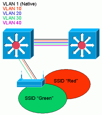
This section discusses concepts about how to deploy VLANs on access points and refers to this network diagram.
In this sample network, VLAN 1 is the Native VLAN, and VLANs 10, 20, 30 and 40 exist, and are trunked to another switch chassis. Only VLANs 10 and 30 are extended into the wireless domain. The Native VLAN is required to provide management capability and client authentications.
Access Point Configuration
In order to configure the access point for VLANs, complete these steps:
-
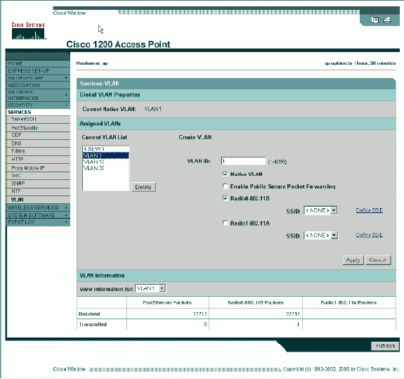
From the AP GUI, click Services > VLAN to navigate to the Services: VLAN page .
-
The first step is to configure the native VLAN. From the Current VLAN List, select New.
-
Enter the VLAN number of the Native VLAN in the VLAN ID box. The VLAN number must match the Native VLAN configured on the switch.
-
Because interface BVI 1 is associated to the subinterface of the Native VLAN, the IP address assigned to interface BVI 1 must be in the same IP subnet as other infrastructure devices on the network (that is, the interface SC0 on a Catalyst switch that runs CatOS.)
-
Select the checkbox for the Native VLAN.
-
Select check boxes for the radio interface or interfaces where this VLAN applies.
-
Click Apply.

Or, from the CLI, issue these commands:
AP# configure terminal
Enter configuration commands, one per line.  End with CNTL/Z.
AP(config)# interface Dot11Radio0.1
AP(config-subif)# encapsulation dot1Q 1 native
AP(config-subif)# interface FastEthernet0.1
AP(config-subif)# encapsulation dot1Q 1 native
AP(config-subif)# end
AP# write memory
-
-
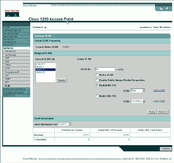
In order to configure other VLANs, follow these steps:
-
From the Current VLAN List, select New.
-
Enter the VLAN number of the desired VLAN in the VLAN ID box. The VLAN number must match a VLAN configured on the switch.
-
Select check boxes for the radio interface or interfaces where this VLAN applies.
-
Click Apply.
Or, from the CLI, issue these commands:
AP# configure terminal
Enter configuration commands, one per line.  End with CNTL/Z.
AP(config)# interface Dot11Radio0.10
AP(config-subif)# encapsulation dot1Q 10
AP(config-subif)# interface FastEthernet0.10
AP(config-subif)# encapsulation dot1Q 10
AP(config-subif)# end
AP# write memory
-
Repeat steps 2a through 2d for each VLAN desired or enter these commands from the CLI with appropriate changes to the subinterface and VLAN numbers:
AP# configure terminal
Enter configuration commands, one per line.  End with CNTL/Z.
AP(config)# interface Dot11Radio0.30

AP(config-subif)# encapsulation dot1Q 30

AP(config-subif)# interface FastEthernet0.30

AP(config-subif)# encapsulation dot1Q 30

AP(config-subif)# end
AP# write memory
-
-
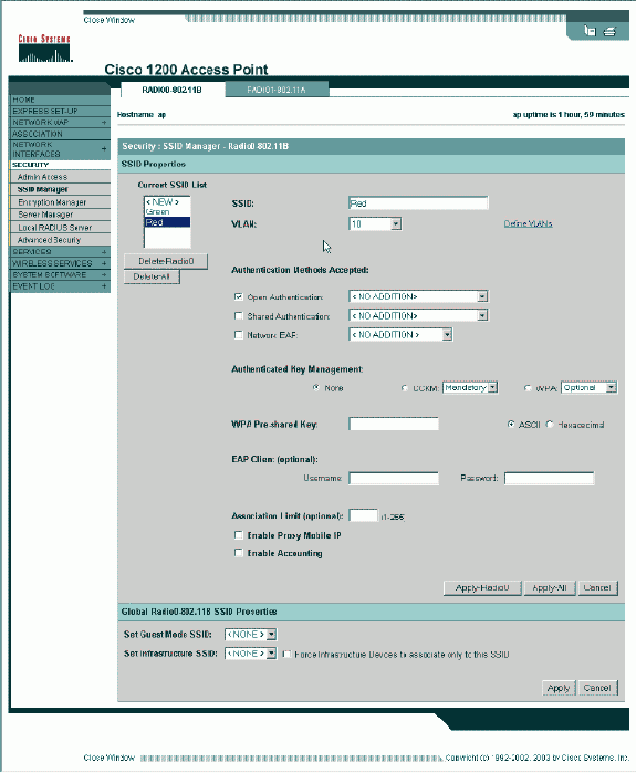
The next step is to associate the configured VLANs to the SSIDs. In order to do this, click Security > SSID Manager.
Note: You do not need to associate every VLAN defined on the access point with an SSID. For example, for security reasons, most access point installations do not associate an SSID with the Native VLAN.
-
In order to create a new SSID, choose New.
-
Enter the desired SSID (case-sensitive) in the SSID box.
-
Select the desired VLAN number to associate this SSID with from the dropdown list.
Note: In order to keep this document within its intended scope, security for an SSID is not addressed.
-
Click Apply-RadioX to create the SSID on the selected radio, or Apply-all to create it on all radios.
Or from the CLI, issue these commands:
AP# configure terminal
Enter configuration commands, one per line.  End with CNTL/Z.
AP(config)# interface Dot11Radio0
AP(config-if)# ssid Red
AP(config-if-ssid)# vlan 10
AP(config-if-ssid)# end
AP# write memory
-
-
Repeat steps 3a through 3d for each SSID desired or enter these commands from the CLI with appropriate changes to the SSID.
AP# configure terminal
Enter configuration commands, one per line.  End with CNTL/Z.
AP(config)# interface Dot11Radio0
AP(config-if)# ssid Green
AP(config-if-ssid)# vlan 30
AP(config-if-ssid)# end
AP# write memory
Note: These examples do not include authentication. Some form of authentication (Open, Network-EAP) is required for clients to associate.
VLANs on Bridges
Concepts on Bridges
This section discusses concepts related to how to deploy VLANs on bridges and refers to this network diagram.
In this sample network, VLAN 1 is the Native VLAN, and VLANs 10, 20, 30 and 40 exist. Only VLANs 10 and 30 are extended to the other side of the link. The wireless link is encrypted.
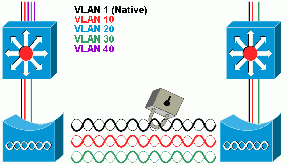
In order to encrypt data that passes over the radio link, apply encryption to only the SSID of the Native VLAN. That encryption applies to all other VLANs. When you bridge, there is no need to associate a separate SSID with each VLAN. VLAN configurations is the same on both the root and non-root bridges.
Bridge Configuration
In order to configure the bridge for VLANs, like the sample network diagram, complete these steps:
-
From the AP GUI, click Services > VLAN to navigate to the Services: VLAN page.
-
The first step is to configure the Native VLAN. In order to do this, choose <New> from the Current VLAN List.
-
Enter the VLAN number of the Native VLAN in the VLAN ID box. This must match the Native VLAN configured on the switch.
-
Because interface BVI 1 is associated to the subinterface of the Native VLAN, the IP address assigned to interface BVI 1 must be in the same IP subnet as other infrastructure devices on the network (i.e. interface SC0 on a Catalyst switch that runs CatOS.)
-
Select the checkbox for the Native VLAN.
-
Click Apply.
Or, from the CLI, issue these commands:
bridge# configure terminal
Enter configuration commands, one per line.  End with CNTL/Z.
bridge(config)# interface Dot11Radio0.1
bridge(config-subif)# encapsulation dot1Q 1 native
bridge(config-subif)# interface FastEthernet0.1
bridge(config-subif)# encapsulation dot1Q 1 native
bridge(config-subif)# end
bridge# write memory
-
-
In order to configure other VLANs, follow these steps:
-
From the Current VLAN List, select New.
-
Enter the VLAN number of the desired VLAN in the VLAN ID box. The VLAN number must match a VLAN configured on the switch.
-
Click Apply.
Or, from the CLI, issue these commands:
bridge# configure terminal
Enter configuration commands, one per line.  End with CNTL/Z.
bridge(config)# interface Dot11Radio0.10
bridge(config-subif)# encapsulation dot1Q 10
bridge(config-subif)# interface FastEthernet0.10
bridge(config-subif)# encapsulation dot1Q 10
bridge(config-subif)# end
bridge# write memory
-
Repeat steps 2a through 2c for each VLAN desired or enter the commands from the CLI with appropriate changes to the subinterface and VLAN numbers.
AP# configure terminal
Enter configuration commands, one per line.  End with CNTL/Z.
bridge(config)# interface Dot11Radio0.30

bridge(config-subif)# encapsulation dot1Q 30

bridge(config-subif)# interface FastEthernet0.30

bridge(config-subif)# encapsulation dot1Q 30

bridge(config-subif)# end
bridge# write memory
-
-
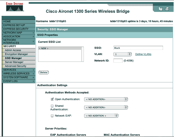
From the SSID Manager (under the Security > SSID Manager menu item,) associate the Native VLAN with an SSID.
Note: When you bridge, the only SSID that you must associate with a VLAN is the one that correlates to the Native VLAN. You must designate this SSID as the Infrastructure SSID.
-
From the Current SSID List, select New.
-
Enter the desired SSID (case-sensitive) in the SSID box.
-
Select the VLAN number that correlates to the Native VLAN from the dropdown list.
Note: In order to keep this document within its intended scope, security for an SSID is not addressed.
-
Click Apply to create the SSID on the radio and associate it to the Native VLAN.
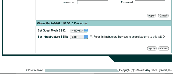
-
Scroll back down to the bottom of the page, and under Global Radio0-802.11G SSID Properties select the SSID from the Set Infrastructure SSID dropdown list. Click Apply.
Or from the CLI, issue these commands:AP# configure terminal Enter configuration commands, one per line. End with CNTL/Z. AP(config)# interface Dot11Radio0 AP(config-if)# ssid Black AP(config-if-ssid)# vlan 1 AP(config-if-ssid)# infrastructure-ssid AP(config-if-ssid)# end AP# write memory
Note: When VLANs are in use, SSIDs are configured under the physical Dot11Radio interface, not under any logical subinterface.
Note: This example does not include authentication. The root and non-root bridges require some form of authentication (Open, Network-EAP, etc.) in order to associate.
-
 Or from the CLI, issue these commands:
Use a RADIUS Server to Assign Users to VLANs
You can configure your RADIUS authentication server to assign users or groups of users to a specific VLAN when they authenticate to the network. For information on this feature, refer to the section Using a RADIUS Server to Assign Users to VLANs of the document Cisco IOS Software Configuration Guide for Cisco Aironet Access Points, 12.4(3g)JA & 12.3(8)JEB.
Use a RADIUS Server for Dynamic Mobility Group Assignment
You can also configure a RADIUS server to dynamically assign mobility groups to users or user groups. This eliminates the need to configure multiple SSIDs on the access point. Instead, you need to configure only one SSID per access point. For information on this feature, refer to the section Using a RADIUS Server for Dynamic Mobility Group Assignment of the document Cisco IOS Software Configuration Guide for Cisco Aironet Access Points, 12.4(3g)JA & 12.3(8)JEB.
Bridge Group Configuration on Access Points and Bridges
In general, bridge groups create segmented switching domains. Traffic is confined to hosts within each bridge group, but not between the bridge groups. The switch forwards traffic only among the hosts that make up the bridge group, which restricts broadcast and multicast traffic (flooding) to only those hosts. Bridge groups relieve network congestion and provide additional network security when they segment traffic to certain areas of the network.
Refer to Bridging Overview for detailed information.
In a wireless network, bridge groups are configured on the wireless access points and bridges in order for the data traffic of a VLAN to be transmitted from wireless media to the wired side and vice versa.
Perform this step from the AP CLI in order to enable bridge groups globally on the access point/bridge.
This example uses the bridge-group number 1.
Ap(configure)#bridge 1
Note: You can number your bridge groups from 1 to 255.
Configure the radio interface and the Fast Ethernet interface of the wireless device to be in the same bridge group. This creates a path between these two different interfaces, and they are in the same VLAN for tagging purposes. As a result, the data transmitted from the wireless side through the radio interface is transmitted to the Ethernet interface to which the wired network is connected and vice versa. In other words, radio and Ethernet interfaces that belong to the same bridge group actually bridge the data between them.
In an access point/bridge, you need to have one bridge group per VLAN so that traffic can pass from the wire to the wireless and vice versa. The more VLAN you have that need to pass traffic across the wireless, the more bridge groups that are needed.
For example, if you have only one VLAN to pass traffic across the wireless to wired side of your network, configure only one bridge group from the CLI of the AP/bridge. If you have multiple VLANs to pass traffic from the wireless to wired side and vice versa, configure bridge groups for each VLAN at the radio sub-interface, as well as the Fast Ethernet sub-interface.
-
Configure the bridge group in the wireless interface with the bridge group dot11radio interface command.
This is an example.
AP# configure terminal
Enter configuration commands, one per line.  End with CNTL/Z.
AP(config)# interface Dot11Radio0.1
Ap(config-subif)# encapsulation dot1q 1 native
Ap(config-subif)# bridge group 1
 !--- Here "1" represents the bridge group number.

ap(config-subif)# exit
-
Configure the bridge group with the same bridge group number («1» in this example) in the Fast Ethernet interface so that VLAN 1 traffic is passed across the wireless interface to this wired side and vice versa.
Ap(config)# interface fastEthernet0.1
Ap(config-subif)# encapsulation dot1q 1 native
Ap(config-subif)# bridge group 1
 !--- Here "1" represents the bridge group number.

Ap(config-subif)# exit
Note: When you configure a bridge group on the radio interface, these commands are set automatically.
-
bridge-group 1 subscriber-loop-control
-
bridge-group 1 block-unknown-source
-
no bridge-group 1 source-learning
-
no bridge-group 1 unicast-flooding
-
bridge-group 1 spanning-disabled
Note: When you configure a bridge group on the Fast Ethernet interface, these commands are set automatically.
-
no bridge-group 1 source-learning
-
bridge-group 1 spanning-disabled
-
Integrated Routing and Bridging (IRB)
Integrated routing and bridging makes it possible to route a specific protocol between routed interfaces and bridge groups, or route a specific protocol between bridge groups. Local or unroutable traffic can be bridged among the bridged interfaces in the same bridge group, while routable traffic can be routed to other routed interfaces or bridge groups
With integrated routing and bridging, you can do this:
-
Switch packets from a bridged interface to a routed interface
-
Switch packets from a routed interface to a bridged interface
-
Switch packets within the same bridge group
Enable IRB on the wireless access points and bridges in order to route your traffic between bridge groups or between routed interfaces and bridge groups. You need an external router or a Layer 3 switch in order to route between bridge groups or between bridge groups and routed interfaces.
Issue this command in order to enable IRB in the AP/bridge.
AP(configure)#bridge irb
Integrated routing and bridging uses the concept of a Bridge-Group Virtual Interface (BVI) in order to route traffic between routed interfaces and bridge groups or between bridge groups.
A BVI is a virtual interface within the Layer 3 switch router that acts like a normal routed interface. A BVI does not support bridging but actually represents the correspondent bridge group to routed interfaces within the Layer 3 switch router. It has all the network layer attributes (such as a network layer address and filters) that apply to the correspondent bridge group. The interface number assigned to this virtual interface corresponds to the bridge group that this virtual interface represents. This number is the link between the virtual interface and the bridge group.
Perform these steps in order to configure the BVI on access points and bridges.
-
Configure the BVI and assign the correspondent number of the bridge group to the BVI. This example assigns bridge group number 1 to the BVI.
Ap(configure)#interface BVI 1
AP(config-if)#ip address 10.1.1.1 255.255.0.0
 !--- Assign an IP address to the BVI.

Ap(config-if)#no shut
-
Enable a BVI to accept and route routable packets received from its correspondent bridge group.
Ap(config)# bridge 1 route ip!---

!--- This example enables the BVI to accept and route the IP packet.
It is important to understand that you only need a BVI for the management/native VLAN in which the AP is located (in this example, VLAN 1). You do not need a BVI for any other subinterface, irrespective of how many VLANs and bridge groups you configure on your AP/bridge. This is because you tag the traffic in all other VLANs (except the native VLAN) and send it out to the switch though a dot1q trunked interface onto the wired side. For example, if you have 2 VLANs on your network, you need two bridge groups, but only one BVI correspondent to the management VLAN is sufficient in your wireless network.
When you enable routing for a given protocol on the bridge group virtual interface, packets that come from a routed interface, but are destined for a host in a bridged domain, are routed to the bridge group virtual interface and are forwarded to the correspondent bridged interface.
All traffic that is routed to the bridge group virtual interface is forwarded to the correspondent bridge group as bridged traffic. All routable traffic received on a bridged interface is routed to other routed interfaces as if it comes directly from the bridge group virtual interface.
Refer to Configure Bridging for more detailed information on bridging and IRB.
Interaction with Related Switches
In this section, you are presented with the information to configure, or verify the configuration of the Cisco switches that connect to Cisco Aironet wireless equipment.
Note: In order to find additional information on the commands used in this document, use the Command Lookup Tool (registered customers only) .
Switch Configuration—Catalyst OS
In order to configure a switch that runs Catalyst OS to trunk VLANs to an access point, the command syntax is set trunk <module #/port #> on dot1q and set trunk <module #/port #> <vlan list>.
An example from to the sample network diagram, is:
set trunk 2/1 on dot1q
set trunk 2/1 1,10,30
Switch Configuration—IOS Based Catalyst Switches
From interface configuration mode, enter these commands, if you want to:
-
Configure the switchport to trunk VLANs to an access point
-
On a Catalyst switch that runs IOS
-
The CatIOS includes but is not limited to:
-
6×00
-
4×00
-
35×0
-
295x
-
switchport mode trunk
switchport trunk encapsulation dot1q
switchport nonegotiate
switchport trunk native vlan 1
switchport trunk allowed vlan add 1,10,30
Note: IOS based Cisco Aironet wireless equipment does not support Dynamic Trunking Protocol (DTP), so the switch must not try to negotiate it.
Switch Configuration—Catalyst 2900XL/3500XL
From interface configuration mode, enter these commands, if you want to configure the switchport to trunk VLANs to an access point on a Catalyst 2900XL or 3500XL switch that runs IOS:
switchport mode trunk
switchport trunk encapsulation dot1q
switchport trunk native vlan 1
switchport trunk allowed vlan 1,10,30
Verify
Use this section to confirm that your configuration works properly.
Verify the Wireless Equipment
-
show vlan—displays all VLANs currently configured on the access point, and their status
ap#show vlan Virtual LAN ID: 1 (IEEE 802.1Q Encapsulation) vLAN Trunk Interfaces: FastEthernet0.1 Dot11Radio0.1 Virtual-Dot11Radio0.1 This is configured as native Vlan for the following interface(s) : FastEthernet0 Dot11Radio0 Virtual-Dot11Radio0 Protocols Configured: Address: Received: Transmitted: Bridging Bridge Group 1 36954 0 Bridging Bridge Group 1 36954 0 Virtual LAN ID: 10 (IEEE 802.1Q Encapsulation) vLAN Trunk Interfaces: FastEthernet0.10 Dot11Radio0.10 Virtual-Dot11Radio0.10 Protocols Configured: Address: Received: Transmitted: Bridging Bridge Group 10 5297 0 Bridging Bridge Group 10 5297 0 Bridging Bridge Group 10 5297 0 Virtual LAN ID: 30 (IEEE 802.1Q Encapsulation) vLAN Trunk Interfaces: FastEthernet0.30 Dot11Radio0.30 Virtual-Dot11Radio0.30 Protocols Configured: Address: Received: Transmitted: Bridging Bridge Group 30 5290 0 Bridging Bridge Group 30 5290 0 Bridging Bridge Group 30 5290 0 ap# -
show dot11 associations—displays information about associated clients, per SSID/VLAN
ap#show dot11 associations

802.11 Client Stations on Dot11Radio0:

SSID [Green] :

SSID [Red] :

Others:  (not related to any ssid)

ap#
Verify the Switch
-
On a Catalyst OS based switch, show trunk <module #/port #>—displays the status of a trunk on a given port
Console> (enable) show trunk 2/1
* - indicates vtp domain mismatch
Port      Mode         Encapsulation  Status        Native vlan
--------  -----------  -------------  ------------  -----------
 2/1      on           dot1q          trunking      1

Port      Vlans allowed on trunk
--------  ----------------------------------------------------------------
 2/1      1,10,30

Port      Vlans allowed and active in management domain
--------  ----------------------------------------------------------------
 2/1      1,10,30

Port      Vlans in spanning tree forwarding state and not pruned
--------  ----------------------------------------------------------------
 2/1      1,10,30
Console> (enable)
-
On a IOS based switch, show interface fastethernet <module #/port #> trunk —displays the status of a trunk on a given interface
2950g#show interface fastEthernet 0/22 trunk

Port        Mode         Encapsulation  Status        Native vlan
Fa0/22      on           802.1q         trunking      1

Port        Vlans allowed on trunk
Fa0/22      1,10,30

Port        Vlans allowed and active in management domain
Fa0/22      1,10,30

Port        Vlans in spanning tree forwarding state and not pruned
Fa0/22      1,10,30
2950gA#
-
On a Catalyst 2900XL/3500XL switch, show interface fastethernet <module #/port #> switchport —displays the status of a trunk on a given interface
cat3524xl#show interface fastEthernet 0/22 switchport
Name: Fa0/22
Switchport: Enabled
Administrative mode: trunk
Operational Mode: trunk
Administrative Trunking Encapsulation: dot1q
Operational Trunking Encapsulation: dot1q
Negotiation of Trunking: Disabled
Access Mode VLAN: 0 ((Inactive))
Trunking Native Mode VLAN: 1 (default)
Trunking VLANs Enabled: 1,10,30,1002-1005
Trunking VLANs Active: 1,10,30
Pruning VLANs Enabled: 2-1001

Priority for untagged frames: 0
Override vlan tag priority: FALSE
Voice VLAN: none
Appliance trust: none
Self Loopback: No
wlan-cat3524xl-a#
Troubleshoot
There is currently no specific troubleshooting information available for this configuration.
Related Information
- Configuring VLANs (Access Point Configuration Guide)
- Configuring VLANs (Bridge Configuration Guide)
- Trunking Technical Support
- Interaction with Related Switches
- System Requirements to Implement Trunking
- Overview of Bridging
- Wireless Authentication Types on a Fixed ISR Configuration Example
- Wireless Authentication Types on Fixed ISR Through SDM Configuration Example
- Wireless LAN Connectivity Using an ISR with WEP Encryption and LEAP Authentication Configuration Example
- Basic Wireless LAN Connection Configuration Example
- Technical Support & Documentation — Cisco Systems
Подборка инструкций по настройке VLAN на оборудовании Cisco. Примеры конфигурирования, описания возможных проблем, настройки и параметры.
Введение в виртуальные локальные сети VLAN
Если вы совсем новичок в теме, начните с этого видео,
посвященного технологии VLAN/
Пожалуй самое доступное объяснение:
Настройка VLAN в Cisco Packet Tracer
В данном уроке мы познакомимся с технологией VLAN, научимся
создавать их на коммутаторах, настраивать access и trunk порты.
Одно из лучших объяснений работы VLAN на оборудовании Cisco.
У кого бесконечный «Translating….» нажмите Ctrl + Shift +
6
Добавлять VLAN в транк только «switchport trunk allowed vlan add», чтобы
остальные не потерялись.
Учтите, что вы не пробросите VLAN без транка.
у коммутаторов есть два режима порта, это access, используется как правило для
конечных устройств (компы, принтеры, телефоны) и trunk — настраивается между
свичами. Access порт тегирует входящий трафик в коммутатор и растегирует
исходящий. Trunk порт не занимается тегированием, он просто прокидывает пакеты
основываясь на метках влана (тегах).
Настройка VLAN+NAT+DHCP
в Cisco Packet
Tracer
Еще одно подробное руководство по настройке VLAN на
оборудовании Cisco.
Маршрутизация между Cisco VLAN. Три варианта дизайна
В этом видео рассказывается о том, как работает
маршрутизация между виртуальными сетями Virtual LAN или Vlan, которая также
называется Inter vlan routing. Подробно
на уровне CCNA рассказывается какой дизайн сети выбрать, в чем преимущества и
недостатки каждого варианта дизайна.
Более чем подходит для подготовке к сертификационному тесту
CCNA Routing and Switching. Вам нужно разделить сеть на Vlan? Нужно настроить
взаимодействие. В видео рассматриваются три варианта построения маршрутизации
между Vlan. Обсуждаются плюсы и минусы каждого, а также применимость на
практике.
Как настроить VLAN
на коммутаторах Cisco Catalyst
2960
В этом видео показано на практике, как создать VLAN на
коммутаторе Cisco 2960, переключить порты в определенный VLAN, а также
передавать трафик между несколькими коммутаторами.
Настройка Native Vlan на Cisco
Native VLAN — это понятие в стандарте 802.1Q, которое
обозначает VLAN на коммутаторе, где все кадры идут без тэга, т.е. трафик
передается нетегированным. По умолчанию это VLAN 1. В некоторых моделях коммутаторов Сisco это можно изменить,
указав другой VLAN как native.
Если коммутатор получает нетегированные кадры на транковом
порту, он автоматически причисляет их к Native VLAN. И точно так же кадры,
генерируемые с не распределенных портов, при попадании в транк-порт
причисляются к Native VLAN.
Трафик, который принадлежит другим VLANам, тегируется с
указанием соответствующего VLAN ID внутри тега.
Пример настройки VLAN 5 как native на коммутаторе Cisco
sw1(config)# interface f0/10
sw1(config-if)# switchport trunk native vlan 5
Теперь весь трафик, принадлежащий VLAN 5 будет передаваться
через транковый интерфейс нетегированным, а весь пришедший на транковый
интерфейс нетегированный трафик будет промаркирован как принадлежащий VLAN’у 5
(по умолчанию VLAN 1).
Из соображений безопасности (например, для защиты от VLAN
Hopping) рекомендуется в транке выполнять тегирование даже для native VLAN.
Включить тегирование фреймов для native VLAN глобально можно с помощью команды
vlan dot1q tag native, просмотреть текущий статус тегирования можно используя
команду show vlan dot1q tag native.
Switch(config)#no vlan dot1q tag native
Switch#sho vlan dot1q tag native
dot1q native vlan tagging is disabled
Настройка Voice VLAN на Cisco
Большинство IP — телефонов, включая Cisco, имеют маленький
коммутатор на 3 порта внутри IP — телефона. Телефон подключается «в разрыв».
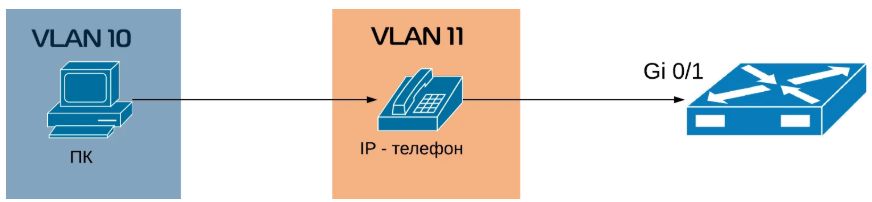
- Первый порт подключается к коммутатору;
- Второй порт подключается к компьютеру;
- Внутренний порт подключает сам телефон;
Как это все работает? Между коммутатором и телефоном у нас
есть так называемый «транк». Порт на телефоне, который подключается к
компьютеру, является портом доступа. Телефона передает весь трафик с компьютера
на коммутатор без каких — либо меток, непомеченным. Трафик с самого телефона
всегда будет помечаться, и в транке будут разрешены только два вышеупомянутых
VLANа.
Если вы уже знакомы с настройкой VLANов, то создание
голосового VLANа не составит для вас вообще никакого труда. Давайте настроим
порт на коммутаторе, где мы будем использовать VLANы 10 и 11.
Сначала мы создаем данные VLANы:
MERION-SW1(config)#vlan 10
MERION-SW1(config-vlan)#name DATA
MERION-SW1(config-vlan)#exit
MERION-SW1(config)#vlan 11
MERION-SW1(config-vlan)#name VOICE
MERION-SW1(config-vlan)#exit
Теперь настроим интерфейс:
MERION-SW1(config)#interface GigabitEthernet
0/1
MERION-SW1(config-if)#switchport mode access
MERION-SW1(config-if)#switchport access vlan 10
MERION-SW1(config-if)#switchport voice vlan 11
MERION-SW1(config-if)#exit
Мы переключили данный порт в режим доступа и настраиваем его
для VLAN 10. Команда switchport voice vlan сообщает коммутатору, чтобы он
использовал VLAN 11 как голосовой VLAN.
Для того, чтобы телефон понял, какой VLAN нужно
использовать, используются два протокола — Cisco Discovery Protocol (CDP) для
телефонов Cisco и Link Layer Discovery Protocol (LLDP) для телефонов от других
вендоров.
Справочная информация
Номера VLAN (VLAN ID)
Номера VLAN
(VLAN ID) могут быть в диапазоне от
1 до 4094:
-
1 — 1005
базовый диапазон (normal-range) - 1002 — 1005 зарезервированы для Token Ring и FDDI VLAN
-
1006
— 4094 расширенный диапазон (extended-range)
Параметры VLAN
При создании или изменении VLAN можно задать следующие параметры:
-
VLAN
ID — Номер VLAN -
VLAN
name (name) — Имя VLAN -
VLAN
type (media) — Тип VLAN (Ethernet, Fiber
Distributed Data Interface [FDDI], FDDI network entity title [NET], TrBRF, или
TrCRF, Token Ring, Token Ring-Net) -
VLAN
state (state) — Состояние VLAN (active или suspended) -
VLAN MTU
(mtu) — Максимальный
размер блока данных, который может быть передан на канальном уровне -
SAID
(said) — Security Association Identifier — идентификатор ассоциации безопасности (стандарт IEEE 802.10) -
Remote SPAN
(remote-span) — Создание VLAN для удаленного
мониторинга трафика (В дальнейшем в такой VLAN можно зеркалировать трафик с какого-нибудь порта, и передать
его через транк на другой коммутатор, в котором из этого VLAN трафик отправить на нужный порт с
подключенным снифером) -
Bridge
identification number для TrBRF VLAN (bridge) — Идентификатор номера моста для
функции TrBRF (Token Ring Bridge Relay Function). Цель функции — создание моста
из колец. -
Ring
number для FDDI и TrCRF VLAN (ring) — Номер кольца для типов VLAN FDDI и TrCRF
(Token Ring concentrator relay functions). TrCRF называют кольца, которые
включены в мост. -
Parent
VLAN number для TrCRF VLAN (parent) — Номер родительского VLAN для типа VLAN
FDDI или Token Ring -
Spanning
Tree Protocol (STP) type для TrCRF VLAN (stp type) — Тип протокола связующего
дерева (STP) для VLAN типа TrCRF -
Translational VLAN number
1 (tb-vlan1) — Номер VLAN для первичного преобразования
одного типа VLAN в
другой -
Translational VLAN number
2 (tb-vlan2) — Номер VLAN для вторичного преобразования
одного типа VLAN в
другой
Значения по умолчанию
| VLAN ID | 1 |
| VLAN name | VLANxxxx, где xxxx четыре цифры номера VLAN (Например: VLAN0003, VLAN0200 и т.д.) |
| SAID | 100000 плюс VLAN ID (Например: 100001 для VLAN 1, 100200 для VLAN 200 и т.д.) |
| VLAN MTU | 1500 |
| Translational VLAN number 1 | 0 |
| Translational VLAN number 2 | 0 |
| VLAN state | active |
| Remote SPAN | disabled |
This section describes How to Configure Vlan On Cisco Router and
VLAN trunks. In post is specifically related to configuration of VLAN, if you
want to learn about what is the VLAN you can
visit the previous post.
Table of Contents
- VLAN ranges on Catalyst switches
- Creation of a VLAN
- Assignment of ports to VLAN networks
- How to Delete a VLan
- Verification of VLAN information
- VLAN Trunks Configuration
- VLAN Troubleshooting
- Troubleshooting trunks configurations
How many VLANs you can configure on Cisco Switch
Different Cisco Catalyst switches support various amounts of VLAN.
The amount of VLANs they support is sufficient to meet the needs of most
organizations. For example, the Catalyst 2960 and 3560 series switches support
more than 4000 VLANs. The normal range VLANs on these switches are numbered
from 1 to 1005, and the extended range VLANs are numbered from 1006 to 4094.
The following illustration shows the available VLANs on a Catalyst 2960 switch
running Cisco IOS, version 15.x.

Normal Range
VLAN
·
It is used in networks of small
and medium businesses and companies.
·
It is identified by a VLAN ID
between 1 and 1005.
·
IDs from 1002 to 1005 are reserved
for Token Ring VLANs and fiber optic distributed data interface (FDDI).
·
IDs 1 and 1002 to 1005 are created
automatically and cannot be deleted.
·
The settings are stored in a VLAN
database file, called vlan.dat. The vlan.dat file is located in the flash
memory of the switch.
·
The VLAN trunk link protocol
(VTP), which allows you to manage VLAN settings between switches, can only
discover and store VLAN networks of normal range.
Extended VLAN
Range
·
It enables service providers to
expand their infrastructure to a larger number of customers. Some global
companies may be large enough to need the IDs of extended range VLANs.
·
They are identified by a VLAN ID
between 1006 and 4094.
·
The settings are not written to
the vlan.dat file.
·
They support fewer VLAN features
than normal range VLANs.
·
They are saved, by default, in the
running configuration file.
·
VTP does not learn extended range
VLANs.
How to create VLAN on Cisco Switch
When
configuring VLAN networks of normal range, the configuration details are stored
in the flash memory of the switch in a file called vlan.dat. The flash memory
is persistent and does not require the copy running-config startup-config command.
However, because other details are usually configured on Cisco switches at the
same time that VLANs are created, it is advisable to save the changes to the
running configuration in the startup configuration. The following table shows
the syntax of the Cisco IOS command that is used to add a VLAN to a switch and
assign it a name. It is recommended to name each VLAN in the configuration of a
switch.
|
Description |
Command |
|
Enter global |
S1 # configure terminal |
|
Create a VLAN with a |
S1 (config) #vlan id-vlan |
|
Specify a unique name to |
S1 (config-vlan) #name |
|
Return to privileged EXEC |
S1 (config-vlan) # end |
|
Table of Commands for Creating a VLAN. |
VLAN Configuration Example
In following figure, it is
shown how VLAN is configured for students (VLAN 20) on switch S1. In the
topology example, the student’s computer (PC2) has not yet been associated with
any VLAN, but has the IP address 172.17.20.22.

S1# configure terminal
S1(config)# vlan 20
S1(config-vlan)# name student
S1(config-vlan)# end

The switchport
access vlan command forces the creation of a VLAN if
it does not already exist on the switch. For example, VLAN 30 is not
present in the result of the show vlan brief command of
the switch. If the switchport access vlan 30 command is
entered on any interface without prior configuration, the
switch displays the following:
% Access VLAN does not exist. Creating vlan 30
How change the membership
of Port of VLAN
There are several ways to
change the membership of ports in a VLAN. The following table shows the
syntax for changing the membership of a switch port of VLAN 1 with
the no switchport access vlan command of the interface configuration
mode.
|
Description |
Command |
|
Enter global |
S1 # configure terminal |
|
Remove the VLAN |
S1 (config-if) # no |
|
Return to privileged |
S1 (config-if) # end |
|
VLAN |
CONFIGURATION
EXAMPLE

The F0 / 18 interface
was previously assigned to VLAN 20. The no switchport access vlan command for
the F0 / 18 interface is entered. Examine the result of the show vlan brief
command that follows immediately, as
shown in the previous result. The show vlan brief command shows the type of VLAN assignment and
membership for all switch ports. The show vlan brief command shows a line for each VLAN. The result for
each VLAN includes the name, status and switch ports of the VLAN.
VERIFICATION
EXAMPLE
VLAN 20 is
still active, even if it has no ports assigned. The following scheme shows that
the result of the show interfaces f0 / 18 switchport command verifies that the access VLAN for interface
F0 / 18 has been reset to VLAN 1.

ASSIGNING A
PORT TO A VLAN
The VLAN
membership of a port can be easily changed. It is not necessary to first remove
a port from a VLAN to change its VLAN membership. When the VLAN membership of
an access port is reassigned to another existing VLAN, the new VLAN membership
simply replaces the previous VLAN membership. Next, port F0 / 11 was assigned
to VLAN 20.
S1 # config t
S1 (config) # interface F0 / 11
S1 (config-if) # switchport mode access
S1 (config-if) # switchport access vlan 20
S1 (config-if) # end
How to delete
a VLAN
In the
illustration, the global configuration mode command no vlan id-vlan
is used to remove VLAN 20 from the switch. Switch S1 had a minimal
configuration with all ports in VLAN 1 and an unused VLAN 20 in the VLAN
database. The show vlan brief command
verifies that VLAN 20 is no longer present in the vlan.dat file after
using the no vlan 20 command.
S1 # conf t
S1 (config) # no vlan 20
S1 (config) # end
Caution: Before deleting a VLAN, reassign all member ports to a different
VLAN. Ports that do not transfer to an active VLAN cannot communicate with
other hosts once the VLAN is removed and until they are assigned to an active
VLAN.
Alternatively,
the entire vlan.dat file can be deleted with the delete flash command: vlan.dat
in the privileged EXEC mode. The abbreviated version of the command (delete vlan.dat)
can be used if the vlan.dat file was not moved from its default location. After
issuing this command and reloading the switch, the previously configured VLANs
are no longer present. This returns the switch to the factory default condition
with respect to the VLAN configuration.
VERIFICATION
OF VLAN INFORMATION
Once a VLAN
is configured, the configuration can be validated with the Cisco IOS show
commands.
show vlan [ brief | id id-vlan | name vlan-name | summary ]
The
following table shows the options for the show vlan and show interfaces commands .
|
Description |
Command |
|
Show a line for each VLAN with its name, |
brief |
|
Show information about a single VLAN |
id id-vlan |
|
Show information about a single VLAN |
name vlan-name |
|
Show the summary of VLAN information. |
summary |
|
Show vlan command table |
USE THE SHOW
VLAN COMMAND
In the
following example, the show vlan name student command produces a result that is not easily
interpreted. The show vlan summary command
shows the count of all configured VLANs. The result shows seven VLANs.

USE THE SHOW
INTERFACES VLAN COMMAND
The show
interfaces vlan id-vlan command
shows details that exceed the scope of this course. The important
information appears on the second line of the following scheme, which indicates
that VLAN 20 is active.

VLAN TRUNKS
CONFIGURATION
A VLAN trunk
link is a layer 2 link of the OSI model between two switches that carries
traffic for all VLANs (unless the list of allowed VLANs is restricted manually
or dynamically). To enable trunk links, configure the ports at either end of
the physical link with parallel command sets. To configure a switch port at one
end of a trunk link, use the switchport mode trunk command. With this command,
the interface switches to permanent trunk mode. The port establishes a dynamic
trunk link protocol (DTP) negotiation to convert the link into a trunk link,
even if the interface connected to it does not accept the change. In this
course, the switchport mode trunk command
is the only method that is implemented for trunking configuration.
The following
table shows the syntax of the Cisco IOS command to specify a native VLAN (other
than VLAN 1). In the example, VLAN 99 is configured as a native VLAN with the
switchport trunk native vlan 99 command.
| Description | Command |
|
Enter global configuration mode. |
S1 # configure terminal |
|
Enter the interface configuration mode. |
S1 (config) # interface interface_id |
|
Make the link a trunk link. |
S1 (config-if) # switchport mode trunk |
|
Specify a native VLAN for frames without labels. |
S1 (config-if) # switchport trunk native vlan id_vlan |
|
Specify the list of VLANs that will be allowed on the trunk link. |
S1 (config-if) # switchport trunk allowed vlan vlan-list |
|
Return to privileged EXEC mode. |
S1 (config-if) # end |
|
Trunk Link Configuration Table |
Use the switchport
trunk allowed vlan Cisco IOS
list-vlan command to specify the list of
VLANs that will be allowed on the trunk link.
VLAN TOPOLOGY EXAMPLE
In following
image, VLANs 10, 20 and 30 support the Teaching, Student and Guest computers
(PC1, PC2 and PC3). Port F0 / 1 of switch S1 was configured as a trunk link
port and forwards traffic for VLANs 10, 20 and 30. VLAN 99 was configured as a
native VLAN.

VLAN 10 — Faculty / Staff — 172.17.10.0/24
VLAN 20 — Students — 172.17.20.0/24
VLAN 30 — Guest — 172.17.30.0/24
VLAN 99 — Native — 172.17.99.0/24
The following
shows the configuration of port F0 / 1 of switch S1 as a trunk link port. The
native VLAN is changed to VLAN 99 and the list of allowed VLANs is restricted
to 10, 20, 30 and 99.
S1 (config) # interface FastEthernet0 / 1
S1 (config-if) # switchport mode trunk
S1 (config-if) # switchport trunk native vlan 99
S1 (config-if) # switchport trunk allowed vlan
10,20,30,99
S1 (config-if) # end
RESET THE
TRUNK LINK TO THE DEFAULT STATE
The following
table shows the commands to remove the allowed VLANs and restore the native
VLAN from the trunk. When it is restored to the default state, the trunk
link allows all VLANs and uses VLAN 1 as a native VLAN.
| Description | Command |
|
Enter global configuration mode. |
S1 # configure terminal |
|
Enter the interface configuration mode. |
S1 (config) # interface interface_id |
|
Establish the trunk link to allow all VLANs. |
S1 (config-if) # no switchport trunk allowed vlan |
|
Reset the native VLAN to the default value. |
S1 (config-if) # no switchport trunk native vlan |
|
Return to privileged EXEC mode. |
S1 (config-if) # end |
|
Reset table of values configured in trunks |
The commands
used to reset all trunk link features of a trunk interface to the default
settings are now displayed. The show interfaces f0 / 1 switchport command reveals
that the trunk link was reconfigured in a default state.

Finally, the
example result shows the commands used to remove the trunk link feature of port
F0 / 1 of switch S1. The show interfaces f0 / 1 switchport command reveals that
the F0 / 1 interface is now in static access mode.

TRUNK LINK
CONFIGURATION VERIFICATION
The following
result shows the configuration of port F0 / 1 of switch S1. The configuration
is verified with the command show interfaces id-switchport interface.

In the
highlighted upper area, it is shown that the administrative mode of port F0 / 1
was set to trunk. The port is in trunk mode. In the next highlighted area, it
is verified that the native VLAN is VLAN 99. Further down in the result, in the
highlighted lower area, it is shown that all VLANs are enabled on the trunk
link.
VLAN
TROUBLESHOOTING
Each VLAN
must correspond to a single IP subnet . If two devices on the same VLAN have
different subnet addresses, they cannot communicate. This is a frequent problem
and is easily solved by identifying the incorrect configuration and changing
the subnet address to a correct address.
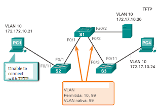
In above
image, PC1 cannot connect to the Web / TFTP server shown.
The
verification of the IPv4 configuration options of PC1, which is shown in the
following result, reveals the most frequent error in the configuration of VLAN
networks: a badly configured IPv4 address. PC1 was configured with IPv4 address
172.172.10.21, but should have been configured with address 172.17.10.21.

PC1>
ipconfig
IP
Address ……………….: 172.172.10.21
Subnet
Mask ………………: 255.255.0.0
Default Gateway …………..:
0.0.0.0
The PC1 Fast
Ethernet configuration dialog box shows the updated IPv4 address, 172.17.10.21.
The result shown at the bottom indicates that PC1 regained connectivity to the
Web / TFTP server located at IPv4 address 172.17.10.30.
PC1> ping 172.17.10.30
Pinging 172.17.10.30 with 32
bytes of data:
Reply from 172.17.10.30: Bytes
= 32 Time = 147ms TTL = 128
How to Troubleshoot
MISSING VLANS
If there is
still no connection between the devices in a VLAN but the IP addressing
problems have been ruled out.
Step 1 : Use
the show vlan command to verify if the
port belongs to the expected VLAN. If the port was assigned to an incorrect
VLAN, use the switchport access vlan command
to correct VLAN membership. Use the show mac address-table command to review which addresses were obtained on a
particular port on the switch and to which VLAN that port was assigned, as
shown below:

Step 2 : If
the VLAN to which the port was assigned is removed, the port becomes inactive.
The ports of a deleted VLAN will not be indicated in the result of the show
vlan command . Use the show interfaces
switchport command to verify that the
inactive VLAN is assigned to the port, as shown:

In the
previous result, the MAC addresses that were obtained in the F0 / 1 interface
are shown. It can be seen that the MAC address 000c.296a.a21c was obtained at
interface F0 / 1 of VLAN 10. If this is not the expected VLAN number, change
the VLAN port membership with the switchport access vlan command. Each port of
a switch belongs to a VLAN. If the VLAN to which the port belongs is deleted,
it becomes inactive. None of the ports belonging to the VLAN that was deleted
can communicate with the rest of the network. Use the show interface f0 / 1
switchport command to verify if the
port is inactive. If the port is inactive, it does not work until the VLAN is
created with the global configuration command vlan id-vlan
or the VLAN is removed from the port with the no switchport access
vlan id-vlan command .
TROUBLESHOOTING
TRUNKS
One of the
common tasks of network administrators is to solve problems of trunk or port
link formation that behaves incorrectly as trunk ports. Occasionally, a switch
port may behave as a trunk link port, even if it was not configured as such.
For example, an access port can accept frames from VLAN networks other than the
VLAN to which it was assigned. This is known as «VLAN filtration.»
TROUBLESHOOTING
COMMANDS
To solve
problems of trunk links that are not formed or VLAN filtering, proceed as
follows:
·
Step 1 : Use the show interfaces
trunk command to verify if there is a
match between the local native VLAN and the peers. If the native VLAN does not
match at both ends, there is a VLAN leak.
·
Step 2 : Use the show interfaces
trunk command to verify if a trunk link
was established between the switches. Staticly configure trunks whenever
possible. Cisco Catalyst switch ports use DTP by default and attempt to
negotiate a trunk.
To show the
status of the trunk link and the native VLAN used in it, and verify the
establishment of that link, use the show interfaces trunk command . Next, it is shown that the native VLAN at
one end of the trunk link was changed to VLAN 2. If one end of the trunk link
is configured as native VLAN 99 and the other end as native VLAN 2, the frames
that are sent from the trunk VLAN 99 on one end are received on VLAN 2 on the other
end. VLAN 99 is filtered in segment VLAN 2.
SW1 # show interfaces f0 / 1 trunk
Port Mode Encapsulation Status Native vlan
Fa0 / 1 car 802.1q
trunking 2
CDP displays
a native VLAN incompatibility warning on a trunk link with this message:
* Mar 1 06: 45: 26.232:% CDP-4-NATIVE_VLAN_MISMATCH:
Native VLAN mismatch discovered on FastEthernet0 / 1 (2), with S2 FastEthernet0
/ 1 (99).
If there is a
native VLAN incompatibility, connectivity problems occur on the network. Data
traffic for VLANs other than the two native VLANs configured is correctly
propagated through the trunk link, but data related to any of the native VLANs
is not propagated correctly through the trunk link.
As shown
above, the incompatibility problems of the native VLAN do not prevent the trunk
link from forming. To resolve a native VLAN incompatibility, configure the
native VLAN to be the same VLAN on both sides of the link.
COMMON ISSUES
WITH TRUNKS
In general,
trunk link problems are due to incorrect configuration. When configuring VLANs
and trunks in a switched infrastructure, the most frequent configuration errors
are as follows:
·
Incompatibility of native
VLAN: Trunk link ports were configured
with different native VLANs. This configuration error generates console notifications
and can cause routing problems between VLANs, among other inconveniences. This
represents a security risk.
For example,
one port is defined as VLAN 99 and the other as VLAN 100.
·
Incompatibilities of trunk
mode: A trunk port is configured in a
mode that is not compatible for trunk links on the corresponding peer port.
These configuration errors cause the trunk link to stop working. Ensure that
both sides of the trunk link are configured with the switchport mode trunk
command . The other trunk link
configuration commands exceed the scope of this course.
For example,
one side of the trunk link is configured as an access port.
VLANs allowed
on trunk links: The list of VLANs
allowed on a trunk link with the current VLAN trunk requirements was not
updated. In this case, unexpected traffic or no traffic is sent to the trunk
link.
The list of
allowed VLANs does not support the current VLAN trunk requirements.
If a problem
with a trunk link is detected and the cause is unknown, start troubleshooting
with a review of the trunk links to determine if there is a native VLAN
incompatibility. If that is not the cause, check if there is a trunk link mode
incompatibility and, finally, check the list of VLANs allowed on the trunk
link. On the next two pages, we discuss how to troubleshoot frequent trunk
links.
WRONG PORT
MODE
Typically,
trunk links are statically configured with the switchport mode trunk
command . The trunk link ports of Cisco
Catalyst switches use DTP to negotiate link status. When a port on a trunk link
is configured with a trunk link mode that is not compatible with the
neighboring trunk link port, a trunk link cannot be formed between the two
switches.
INCORRECT
VLAN LIST
For a VLAN
traffic to be transmitted through a trunk link, it must be allowed on that
link. To do this, use the switchport trunk allowed vlan command id-vlan .