Huawei uses machine translation combined with human proofreading to translate this document to different languages in order to help you better understand the content of this document.
Note: Even the most advanced machine translation cannot match the quality of professional translators.
Huawei shall not bear any responsibility for translation accuracy and it is recommended that you refer to the English document (a link for which has been provided).
QoS
- Example for Configuring a Traffic Policy to Limit the Rate of High-Bandwidth Traffic
- Example for Configuring a Traffic Policy to Block Traffic
- Example for Configuring IP-based Complex Traffic Classification
- Example for Configuring Redirection on Dual Outbound Interfaces
- Example for Configuring Congestion Management and Congestion Avoidance
Example for Configuring a Traffic Policy to Limit the Rate of High-Bandwidth Traffic
This section provides an example for configuring a traffic policy to limit the rate of high-bandwidth traffic to protect the bandwidth of key services on the network.
Applicable Products and Versions
- This configuration example applies to NE40E, ME60 and NE20E series products running V800R010C00 or later.
- This configuration example applies to NetEngine 8000 X and NetEngine 8000 M series products running V800R012C00 or later.
Networking Requirements
In Figure 1-104, the traffic rate of Eth-Trunk 1, which connects the edge router PE1 of a WAN to LAN X, exceeds the limit. According to fault locating results, a host with the IP address 10.1.1.1/32 on LAN X is downloading many files from a remote server with the IP address 10.2.1.1/32, causing excessive bandwidth consumption. You can limit the traffic rate to protect the bandwidth of key services on the network.
Figure 1-104 Configuring a traffic policy to limit the rate of high-bandwidth traffic
Configuration Roadmap
-
Configure an advanced ACL to match traffic with the source address 10.1.1.1/32 and destination address 10.2.1.1/32.
-
Configure a traffic classifier and specify the ACL in the traffic classifier.
-
Configure a traffic behavior and set its action to CAR.
-
Configure a traffic policy, and associate the traffic classifier with the traffic behavior in this policy.
-
Apply the traffic policy to the inbound interface.
Procedure
- Configure an advanced ACL on PE1 to match high-bandwidth traffic.
#
acl name flow-limit advance                                    //Configure an advanced ACL named flow-limit to match high-bandwidth traffic.
 rule 5 permit ip source 10.1.1.1 0 destination 10.2.1.1 0     //Match traffic with the source IP address of 10.2.1.1 and the destination IP address of 10.1.1.1
#
- Configure a traffic classifier.
#
traffic classifier flow-limit operator or                  //Configure a traffic classifier named flow-limit.
 if-match acl name flow-limit                              //Specify the ACL named flow-limit.
#
- Configure a traffic behavior.
#
traffic behavior flow-limit                                 //Configure a traffic behavior named flow-limit.
 car cir 10 pir 10 green pass yellow discard red discard    //Limit the traffic rate. In this example, the values of CIR and PIR are 10 kbit/s. Set these values according to your actual situation.
#
- Configure a traffic policy.
#
traffic-policy flow-limit                                   //Configure a traffic policy named flow-limit.
 classifier flow-limit behavior flow-limit                  //Associate the traffic classifier with the traffic behavior in the traffic policy.
#
- Apply the traffic policy.
#
interface Eth-trunk 1                                      //Enter the view of the inbound interface of high-bandwidth traffic. In this example, the inbound interface is Eth-Trunk 1. Specify an interface according to your actual situation.
 traffic-policy flow-limit outbound                        //Apply the traffic policy to the interface.
#
- Verify the configuration.
Run the display interface [ interface-type [ interface-number ] ] command to view traffic information of the specified interface.
Example for Configuring a Traffic Policy to Block Traffic
This section provides an example for configuring a traffic policy to block traffic to prevent multicast protocol packets from affecting the MAN.
Applicable Products and Versions
- This configuration example applies to NE40E, ME60 and NE20E series products running V800R010C00 or later.
- This configuration example applies to NetEngine 8000 X and NetEngine 8000 M series products running V800R012C00 or later.
Networking Requirements
In Figure 1-105, a MAN carries multicast services, and multicast replication points are located on the MAN edge router. To prevent multicast protocol packets from affecting the MAN, the multicast protocol packets sent by the downstream devices must be blocked on the edge devices of the MAN.
Figure 1-105 Configuring a traffic policy to block traffic
Configuration Roadmap
-
Configure an advanced ACL to match multicast protocol packets such as those of PIM and IGMP.
-
Configure a traffic classifier and specify the ACL in the traffic classifier.
-
Configure a traffic behavior and set its action to deny.
-
Configure a traffic policy and associate the traffic classifier with the traffic behavior in this policy.
-
Apply the traffic policy to all network-side interfaces.
Procedure
- Configure an advanced ACL to match multicast protocol packets such as those of PIM and IGMP.
#
acl number 3001                                           //Configure an ACL.
 rule 10 permit 103 destination 224.0.0.13 0
 rule 20 permit igmp destination 224.0.0.1 0
 rule 30 permit ip source 10.89.8.0 0.0.0.255
 rule 40 permit ip source 10.222.8.0 0.0.0.255
#
#
- Configure a traffic classifier.
#
traffic classifier 3001 operator or                     //Configure a traffic classifier.
 if-match acl 3001
#
- Configure a traffic behavior.
#
traffic behavior 3001                                   //Configure a traffic behavior.
 deny
#
- Configure a traffic policy.
#
traffic policy LOOP_AVOID                             //Configure a traffic policy.
 share-mode
 statistics enable
 classifier 3001 behavior 3001
#
- Apply the traffic policy.
#
interface Eth-Trunk1
 traffic-policy LOOP_AVOID outbound                  //Apply the traffic policy.
 trust upstream default
#
- Verify the configuration.
Run the display interface [ interface-type [ interface-number ] ] command to view traffic information of the specified interface.
Example for Configuring IP-based Complex Traffic Classification
This section provides an example of how to configure IP-based complex traffic classification.
Applicable Products and Versions
- This configuration example applies to NE40E, ME60 and NE20E series products running V800R010C00 or later.
- This configuration example applies to NetEngine 8000 X and NetEngine 8000 M series products running V800R012C00 or later.
Networking Requirements
As shown in Figure 1-106, MF classification is configured on Device C to implement access control between Device A and Device B. In addition, traffic statistics can be collected to verify packet sending and receiving.
Interfaces 1 and 2 in this example are GE 0/1/0 and GE 0/2/0, respectively.
Figure 1-106 Configuring a traffic policy based on MF classification
Configuration Roadmap
The configuration roadmap is as follows:
-
Configure an ACL rule.
-
Configure a traffic classifier.
-
Configure a traffic behavior.
-
Configure a traffic policy.
-
Apply the traffic policy.
Data Preparation
To complete the configuration, you need the following data:
-
ACL number
-
Names of the traffic classifier, traffic behavior, and traffic policy, and number of the interface to which the traffic policy is applied
Procedure
- Configure an ACL rule.
<HUAWEI> system-view
[~HUAWEI] sysname DeviceC[*HUAWEI] commit[~DeviceC] acl number 3333[*DeviceC-acl-adv-3333] rule 5 permit ip source 1.1.1.1 0 destination 2.2.2.2 0[*DeviceC-acl-adv-3333] rule 10 permit ip source 2.2.2.2 0 destination 1.1.1.1 0[*DeviceC-acl-adv-3333] commit[~DeviceC-acl-adv-3333] quit - Configure a traffic classifier.
[~DeviceC] traffic classifier c1[*DeviceC-classifier-c1] if-match acl 3333[*DeviceC-classifier-c1] commit[~DeviceC-classifier-c1] quit - Configure a traffic behavior.
[~DeviceC] traffic behavior b1[*DeviceC-behavior-b1] permit[*DeviceC-behavior-b1] commit[~DeviceC-behavior-b1] quit - Configure a traffic policy.
[~DeviceC] traffic policy p1[*DeviceC-trafficpolicy-p1] classifier c1 behavior b1[*DeviceC-trafficpolicy-p1] share-mode[*DeviceC-trafficpolicy-p1] statistic enable[*DeviceC-trafficpolicy-p1] commit[~DeviceC-trafficpolicy-p1] quit - Apply the traffic policy.
[~DeviceC] interface gigabitethernet 0/1/0
[~DeviceC-GigabitEthernet0/1/0] traffic-policy p1 inbound
[*DeviceC-GigabitEthernet0/1/0] traffic-policy p1 outbound
[*DeviceC-GigabitEthernet0/1/0] commit
[~DeviceC-GigabitEthernet0/1/0] quit
[~DeviceC] interface gigabitethernet 0/2/0
[~DeviceC-GigabitEthernet0/2/0] traffic-policy p1 inbound
[*DeviceC-GigabitEthernet0/2/0] traffic-policy p1 outbound
[*DeviceC-GigabitEthernet0/2/0] commit
[~DeviceC-GigabitEthernet0/2/0] quit
- Verify the configuration.
After completing the configurations, run the ping 2.2.2.2 command on Device A to ping Device B, and run the display traffic policy statistics command on Device C to view statistics about traffic exchanged between Device A and Device B.
[~DeviceC] display traffic policy statistics interface gigabitethernet 0/1/0 inbound
Info: The statistics is shared because the policy is shared.
Interface: GigabitEthernet0/1/0
Traffic policy inbound: p1
Traffic policy applied at 2017-08-30 18:30:20
Statistics enabled at 2017-08-30 18:30:20
Statistics last cleared: Never
Rule number: 1 IPv4, 0 IPv6
Current status: OK!
Item                             Packets                      Bytes
-------------------------------------------------------------------
Matched                                5                       500
  +--Passed                            4                       400
  +--Dropped                           1                       100

Last 30 seconds rate
Item                                 pps                        bps
-------------------------------------------------------------------
Matched                                5                       500
  +--Passed                            4                       400
  +--Dropped                           1                       100
Configuration File on Device C
#
sysname DeviceC
#
acl number 3333
 rule 5 permit ip source 1.1.1.1 0 destination 2.2.2.2 0
 rule 10 permit ip source 2.2.2.2 0 destination 1.1.1.1 0
#
traffic classifier c1
 if-match acl 3333
#
traffic behavior b1
 permit
#
traffic policy p1
 share-mode
 statistic enable
 classifier c1 behavior b1
#
interface GigabitEthernet0/1/0
 traffic-policy p1 inbound
 traffic-policy p1 outbound
#
interface GigabitEthernet0/2/0
 traffic-policy p1 inbound
 traffic-policy p1 outbound
#
return
Example for Configuring Redirection on Dual Outbound Interfaces
This section provides an example for configuring redirection on dual outbound interfaces.
Applicable Products and Versions
- This configuration example applies to NE40E, ME60 and NE20E series products running V800R010C00 or later.
- This configuration example applies to NetEngine 8000 X and NetEngine 8000 M series products running V800R012C00 or later.
Networking Requirements
As shown in Figure 1-107, Device A connects to the intranet through interface 1 and connects to the public network through interface 2 and interface 3. By default, traffic from the intranet is transmitted to the public network through interface 3. To enable traffic from the server to be transmitted to the public network through interface 2 and other traffic to the public network through interface 3, configure a traffic policy on Device A.
Interfaces 1 through 3 are GE 0/1/0, GE 0/2/0, and GE 0/3/0, respectively.
Figure 1-107 Configuring redirection on dual outbound interfaces
Configuration Roadmap
The configuration roadmap is as follows:
-
Configure a default route.
-
Configure an ACL rule.
-
Configure traffic classifiers.
-
Configure traffic behaviors.
-
Configure a traffic policy.
-
Apply the traffic policy.
Data Preparation
To complete the configuration, you need the following data:
-
ACL number
-
Names of the traffic classifier, traffic behavior, and traffic policy, and number of the interface to which the traffic policy is applied
Procedure
- Configure the default route so that intranet traffic is transmitted to the public network through interface 3 by default and interface 2 is used as the backup outbound interface.
<HUAWEI> system-view
[~HUAWEI] ip route-static 0.0.0.0 0.0.0.0 10.1.99.1[*HUAWEI] ip route-static 0.0.0.0 0.0.0.0 10.1.99.5 pre 70[*HUAWEI] commit - Configure an ACL rule.
# Configure rule 3001 to match the traffic from the server to other devices on the intranet.
[~HUAWEI] acl 3001[*HUAWEI-acl-adv-3001] rule permit ip source 10.1.40.0 0.0.0.255 destination 10.1.40.0 0.0.0.255[*HUAWEI-acl-adv-3001] rule permit ip source 10.1.40.0 0.0.0.255 destination 10.1.41.0 0.0.0.255[*HUAWEI-acl-adv-3001] rule permit ip source 10.1.40.0 0.0.0.255 destination 10.1.42.0 0.0.0.255[*HUAWEI-acl-adv-3001] commit[~HUAWEI-acl-adv-3001] quit# Configure rule 3002 to match the traffic with the source address being the IP address of the server.
[~HUAWEI] acl 3002[*HUAWEI-acl-adv-3002] rule permit ip source 10.1.40.0 0.0.0.255[*HUAWEI-acl-adv-3002] commit[~HUAWEI-acl-adv-3002] quit - Configure traffic classifiers.
# Configure a traffic classifier named c1.
[~HUAWEI] traffic classifier c1[*HUAWEI-classifier-c1] if-match acl 3001[*HUAWEI-classifier-c1] commit[~HUAWEI-classifier-c1] quit# Configure a traffic classifier named c2.
[~HUAWEI] traffic classifier c2[*HUAWEI-classifier-c2] if-match acl 3002[*HUAWEI-classifier-c2] commit[~HUAWEI-classifier-c2] quit - Configure traffic behaviors.
# Configure a traffic behavior named b1.
[~HUAWEI]traffic behavior b1[*HUAWEI-behavior-b1] permit[*HUAWEI-behavior-b1] commit[~HUAWEI-behavior-b1] quit# Configure a traffic behavior b2.
[~HUAWEI] traffic behavior b2[*HUAWEI-behavior-b2] redirect ip-nexthop 10.1.99.5[*HUAWEI-behavior-b2] commit[~HUAWEI-behavior-b2] quit - Configure a traffic policy.
[~HUAWEI] traffic policy p1[*HUAWEI-trafficpolicy-p1] classifier c1 behavior b1[*HUAWEI-trafficpolicy-p1] classifier c2 behavior b2[*HUAWEI-trafficpolicy-p1] commit[~HUAWEI-trafficpolicy-p1] quit - Apply the traffic policy.
[~HUAWEI] interface gigabitethernet 0/1/0
[~HUAWEI-GigabitEthernet0/1/0] traffic-policy p1 inbound
[*HUAWEI-GigabitEthernet0/1/0] commit
[~HUAWEI-GigabitEthernet0/1/0] quit
- Verify the configuration.
After completing the configurations, run the display traffic policy command on Device A to view the configurations of the traffic policy, traffic classifier, and traffic behavior.
[~HUAWEI] display traffic policy user-defined p1
  User Defined Traffic Policy Information:
    Policy: p1
      Total: 5120  Used: 3  Free: 5117
      Description:
      Step: 1
      Share-mode
      Classifier: c1 Precedence: 1
        Behavior: b1
        -none-

      Classifier: c2 Precedence: 2
        Behavior: b2
        Redirecting:
          redirect ip-nexthop 10.1.99.5

      Classifier: default-class Precedence: 65535
        Behavior: be
        -none-
Configuration Files
#
ip route-static 0.0.0.0 0.0.0.0 10.1.99.1
ip route-static 0.0.0.0 0.0.0.0 10.1.99.5 pre 70
#
acl 3001
 rule permit ip source 10.1.40.0 0.0.0.255 destination 10.1.40.0 0.0.0.255
 rule permit ip source 10.1.40.0 0.0.0.255 destination 10.1.41.0 0.0.0.255
 rule permit ip source 10.1.40.0 0.0.0.255 destination 10.1.42.0 0.0.0.255
acl 3002
 rule permit ip source 10.1.40.0 0.0.0.255
#
traffic classifier c1
 if-match acl 3001
traffic classifier c2
 if-match acl 3002
#
traffic behavior b1
 permit
traffic behavior b2
 redirect ip-nexthop 10.1.99.5
#
traffic policy p1
 classifier c1 behavior b1
 classifier c2 behavior b2
#
interface gigabitethernet0/1/0
 traffic-policy p1 inbound
#
return
Example for Configuring Congestion Management and Congestion Avoidance
This section provides an example of how to configure congestion management and congestion avoidance. A device on which congestion avoidance is configured checks the use of network resources and starts to discard packets when it determines that congestion is intensifying.
Applicable Products and Versions
- This configuration example applies to NE40E, ME60 and NE20E series products running V800R010C00 or later.
- This configuration example applies to NetEngine 8000 X and NetEngine 8000 M series products running V800R012C00 or later.
Networking Requirements
As shown in Figure 1-108, Server sends mission-critical data, Telephone sends voice data, and PC1 and PC2 send non-mission-critical data to the network through Device A. On Device A, the rate of the inbound interface GE 0/1/0 is greater than that of the outbound interface GE 0/2/0. Therefore, congestion may occur on GE 0/2/0 and may be intensifying.
In the case of network congestion, the service data from the server and the telephone must be preferentially sent. In addition, the telephone requires 5 Mbit/s bandwidth, and the server requires 4 Mbit/s bandwidth. As PC1 and PC2 are VIP users, bandwidth must be assured for the data that PC1 and PC2 send. The delay must be as low as possible. If congestion intensifies on the network, packets are dropped according to priority.
In this scenario, WFQ and WRED need to be configured on Device A.
Interfaces 1 through 2 in this example are GE 0/1/0, GE 0/2/0.
Figure 1-108 Networking diagram for configuring congestion management and congestion avoidance
Configuration Roadmap
The configuration roadmap is as follows:
- Mark the service priorities of different flows on the inbound interface GE 0/1/0 of Device A.
-
Configure a WRED profile and set the lower drop threshold, upper drop threshold, and drop probability for packets.
-
On the outbound interface GE 0/2/0 of Device A, configure a different scheduling policy for class queues of each service level and apply a configured WRED object to the scheduling policy.
Data Preparation
To complete the configuration, you need the following data:
- ACL numbers, traffic classifier names, traffic behavior names, re-marked service priorities, and traffic policy names
-
WRED profile name, lower and upper drop thresholds, drop probability, and packet color in each queue
-
Interfaces and class queues to which WRED drop policies are applied
Procedure
- Configure ACL rules for packets from Server, Telephone, PC1, and PC2.
<*DeviceA> system-view
[~DeviceA] acl number 2001
[*DeviceA-acl4-basic-2001] rule permit source 10.1.1.3 0.0.0.0
[*DeviceA-acl4-basic-2001] commit
[~DeviceA-acl4-basic-2001] quit
[~DeviceA] acl number 2002
[*DeviceA-acl4-basic-2002] rule permit source 10.1.1.2 0.0.0.0
[*DeviceA-acl4-basic-2002] commit
[~DeviceA-acl4-basic-2002] quit
[~DeviceA] acl number 2003
[*DeviceA-acl4-basic-2003] rule permit source 10.1.1.4 0.0.0.0
[*DeviceA-acl4-basic-2003] commit
[~DeviceA-acl4-basic-2003] quit
[~DeviceA] acl number 2004
[*DeviceA-acl4-basic-2004] rule permit source 10.1.1.5 0.0.0.0
[*DeviceA-acl4-basic-2004] commit
[~DeviceA-acl4-basic-2004] quit
- On GE 0/1/0 of Device A, configure complex traffic classification and mark the service priority of each flow.
[~DeviceA] traffic classifier aa
[*DeviceA-classifier-aa] if-match acl 2001
[*DeviceA-classifier-aa] commit
[~DeviceA-classifier-aa] quit
[~DeviceA] traffic classifier bb
[*DeviceA-classifier-bb] if-match acl 2002
[*DeviceA-classifier-bb] commit
[~DeviceA-classifier-bb] quit
[~DeviceA] traffic classifier cc
[*DeviceA-classifier-cc] if-match acl 2003
[*DeviceA-classifier-cc] commit
[~DeviceA-classifier-cc] quit
[~DeviceA] traffic classifier dd
[*DeviceA-classifier-dd] if-match acl 2004
[*DeviceA-classifier-dd] commit
[~DeviceA-classifier-dd] quit
[~DeviceA] traffic behavior aa
[*DeviceA-behavior-aa] remark ip-precedence 5
[*DeviceA-behavior-aa] car cir 5000
[*DeviceA-behavior-aa] commit
[~DeviceA-behavior-aa] quit
[~DeviceA] traffic behavior bb
[*DeviceA-behavior-bb] remark ip-precedence 4
[*DeviceA-behavior-bb] car cir 4000
[*DeviceA-behavior-bb] commit
[~DeviceA-behavior-bb] quit
[~DeviceA] traffic behavior cc
[*DeviceA-behavior-cc] remark ip-precedence 3
[*DeviceA-behavior-cc] commit
[~DeviceA-behavior-cc] quit
[~DeviceA] traffic behavior dd
[*DeviceA-behavior-dd] remark ip-precedence 2
[*DeviceA-behavior-dd] commit
[~DeviceA-behavior-dd] quit
[~DeviceA] traffic policy ee
[*DeviceA-trafficpolicy-ee] classifier aa behavior aa
[*DeviceA-trafficpolicy-ee] classifier bb behavior bb
[*DeviceA-trafficpolicy-ee] classifier cc behavior cc
[*DeviceA-trafficpolicy-ee] classifier dd behavior dd
[*DeviceA-trafficpolicy-ee] commit
[~DeviceA-trafficpolicy-ee] quit
[~DeviceA] interface gigabiethernet0/1/0
[~DeviceA-GigabitEthernet0/1/0] undo shutdown
[*DeviceA-GigabitEthernet0/1/0] traffic-policy ee inbound
[*DeviceA-GigabitEthernet0/1/0] commit
[~DeviceA-GigabitEthernet0/1/0] quit
The priorities of queues with specific service classes are calculated based on scheduling algorithms.
- If PQ scheduling is configured for all queues with the eight service classes, the priorities of the queues are placed in descending order as follows: CS7 > CS6 > EF > AF4 > AF3 > AF2 > AF1 > BE.
- If PQ scheduling is configured for the BE queue (not applied in most cases) and WFQ scheduling is configured for the queues with the other service classes, the priority of the BE queue is higher than that of the other queues.
- If WFQ scheduling is configured for all queues with the eight service classes, all the queues have the same priority.
- Configure a WRED profile on Device A.
[~DeviceA] port-wred pw
[*DeviceA-port-wred-pw] color green low-limit 70 high-limit 100 discard-percentage 100
[*DeviceA-port-wred-pw] color yellow low-limit 60 high-limit 90 discard-percentage 100
[*DeviceA-port-wred-pw] color red low-limit 50 high-limit 80 discard-percentage 100
[*DeviceA-port-wred-pw] commit
[~DeviceA-port-wred-pw] quit
After you complete the preceding configuration, run the display port-wred configuration verbose command to check the WRED profile parameters.
[~DeviceA] display port-wred configuration verbose
Port wred name : pw --------------------------------------------------- Color Low-limit High-limit Discard-percent --------------------------------------------------- green 70 100 100 yellow 60 90 100 red 50 80 100 Queue Depth : 8000 Reference relationships : NULL - On GE 0/2/0 of Device A, configure class queues and apply the configured WRED object pw to the class queues.
[~DeviceA] interface gigabitethernet0/2/0
[~DeviceA-GigabitEthernet0/2/0] undo shutdown
[*DeviceA-GigabitEthernet0/2/0] port-queue ef pq port-wred pw outbound
[*DeviceA-GigabitEthernet0/2/0] port-queue af4 wfq weight 15 shaping 100 port-wred pw outbound
[*DeviceA-GigabitEthernet0/2/0] port-queue af3 wfq weight 10 shaping 50 port-wred pw outbound
[*DeviceA-GigabitEthernet0/2/0] port-queue af2 wfq weight 10 shaping 50 port-wred pw outbound
[*DeviceA-GigabitEthernet0/2/0] commit
[~DeviceA-GigabitEthernet0/2/0] return
After you complete the preceding configuration, run the display port-queue configuration interface command to view detailed configurations of the class queues.
[~DeviceA] display port-queue configuration interface gigabitethernet 0/2/0 outbound
GigabitEthernet0/2/0 be current configuration: Arithmetic: wfq weight: 10 tm weight: 3 fact weight: 10 shaping(mbps): NA port-wred name: NA af1 current configuration: Arithmetic: wfq weight: 10 tm weight: 3 fact weight: 10 shaping(mbps): NA port-wred name: NA af2 current configuration: Arithmetic: wfq weight: 10 tm weight: 3 fact weight: 10 shaping(mbps): 50 port-wred name: pw af3 current configuration: Arithmetic: wfq weight: 10 tm weight: 3 fact weight: 10 shaping(mbps): 50 port-wred name: pw af4 current configuration: Arithmetic: wfq weight: 15 tm weight: 3 fact weight: 10 shaping(mbps): 100 port-wred name: pw ef current configuration: Arithmetic: pq weight: NA tm weight: NA fact weight: NA shaping(mbps): NA port-wred name: pw cs6 current configuration: Arithmetic: pq weight: NA tm weight: NA fact weight: NA shaping(mbps): NA port-wred name: NA cs7 current configuration: Arithmetic: pq weight: NA tm weight: NA fact weight: NA shaping(mbps): NA port-wred name: NA - Verify the configuration.
When the network has traffic, run the display port-queue statistics [ slot slot-id | interface { interface-type interface-number | interface-name } ] [ cos-value ] outbound command on Device A. The command output shows that the traffic volumes of varying service levels increase rapidly. With the rapid increase in traffic volumes, the volume of discarded traffic also increases rapidly according to the configured WRED drop parameters.
Configuration Files
-
Configuration file of Device A
#
sysname DeviceA#
acl number 2001
rule permit source 10.1.1.3 0
#
acl number 2002
rule permit source 10.1.1.2 0
#
acl number 2003
rule permit source 10.1.1.4 0
#
acl number 2004
rule permit source 10.1.1.5 0
#
traffic classifier cc operator or
if-match acl 2003
traffic classifier dd operator or
if-match acl 2004
traffic classifier aa operator or
if-match acl 2001
traffic classifier bb operator or
if-match acl 2002
#
traffic behavior cc
remark ip-precedence 3
traffic behavior dd
remark ip-precedence 2
traffic behavior aa
car cir 5000
remark ip-precedence 5
traffic behavior bb
car cir 4000
remark ip-precedence 4
#
traffic policy ee
classifier aa behavior aa
classifier bb behavior bb
classifier cc behavior cc
classifier dd behavior dd
#
port-wred pw
color green low-limit 70 high-limit 100 discard-percentage 100
color yellow low-limit 60 high-limit 90 discard-percentage 100
color red low-limit 50 high-limit 80 discard-percentage 100
#
interface GigabitEthernet0/1/0undo shutdown
ip address 10.1.1.1 255.255.255.0
traffic-policy ee inbound
#
interface GigabitEthernet0/2/0undo shutdown
ip address 10.10.1.1 255.255.255.0
port-queue af2 wfq weight 10 shaping 50 port-wred pw outbound
port-queue af3 wfq weight 10 shaping 50 port-wred pw outbound
port-queue af4 wfq weight 15 shaping 100 port-wred pw outbound
port-queue ef pq port-wred pw outbound
#
return
- Example for Configuring a Traffic Policy to Limit the Rate of High-Bandwidth Traffic
- Example for Configuring a Traffic Policy to Block Traffic
- Example for Configuring IP-based Complex Traffic Classification
- Example for Configuring Redirection on Dual Outbound Interfaces
- Example for Configuring Congestion Management and Congestion Avoidance
S2720, S5700, and S6700 V200R019C10 Configuration Guide — QoS
This document describes the configurations of QoS functions, including MQC, priority mapping, traffic policing, traffic shaping, interface-based rate limiting, congestion avoidance, congestion management, packet filtering, redirection, traffic statistics, ACL-based simplified traffic policy, HQoS, and SAC.
Чтобы помочь вам лучше понять содержимое этого документа, компания Huawei перевела его на разные языки, используя машинный перевод, отредактированный людьми.
Примечание: даже самые передовые программы машинного перевода не могут обеспечить качество на уровне перевода, выполненного профессиональным переводчиком.
Компания Huawei не несет ответственность за точность перевода и рекомендует ознакомиться с документом на английском языке (по ссылке, которая была предоставлена ранее).
Traffic Policing, Traffic Shaping, and Interface-based Rate Limiting Configuration
- Overview of Traffic Policing, Traffic Shaping, and Interface-based Rate Limiting
- Understanding Traffic Policing, Traffic Shaping, and Interface-based Rate Limiting
- Application Scenarios for Traffic Policing, Traffic Shaping, and Interface-based Rate Limiting
- Licensing Requirements and Limitations for Traffic Policing, Traffic Shaping, and Interface-based Rate Limiting
- Default Settings for Traffic Policing, Traffic Shaping, and Interface-based Rate Limiting
- Configuring Traffic Policing
- Configuring Traffic Shaping
- Configuring Interface-based Rate Limiting
- Maintaining Traffic Policing, Traffic Shaping, and Interface-based Rate Limiting
- Configuration Examples for Traffic Policing, Traffic Shaping, and Interface-based Rate Limiting
- FAQ About Traffic Policing, Traffic Shaping, and Interface-based Rate Limiting
Updated: 2023-03-02
№ документа:EDOC1100127060
Просмотры:147315
Загрузки: 667
Average rating:
This Document Applies to these Products
Digital Signature File
Reprinted source: Huawei router exchange QOS configuration: https://mp.weixin.qq.com/s/ZjUkOk3weIXd5jAObdGsVQ
session 1 QOS basic concept
QoS: Quality of service Quality of service refers to the data packet control technology that allows user services to obtain the expected service level in terms of packet loss rate, delay, jitter, and bandwidth in network communications. Its goals are:
1. Avoid network congestion
2. Reduce packet loss rate
3. Prevent data packet jitter, that is, regulate the flow rate at both ends of the network to be smooth and transmit at the same rate, and there will be no inconsistent transmission time between data packets and data packets
4. Provide dedicated bandwidth for specific users or services
5. Support implementation business on the network
Three models of IP QOS:
1. Best-Effort model, do your best, the main technology is the default FIFO queue technology in the queue technology
2. IntServ model, resource channels are reserved on all devices along the traffic to ensure the service of the traffic, the waste is more serious, and the devices along the way need to support this function.
3. DiffServ model, differentiated service model. Differentiate different traffic to carry out different policy control, and only need to configure on the local device or interface. It is effective locally and only acts on the forwarding of the local device. There is no need to reserve resources for the equipment along the way. It can be done wherever it is needed. Configuration, currently the most commonly used and practical QOS model.
The following is the QOS diagram of the service model:

DiffServ model

The basic elements of session 2 QoS
1. Traffic classification and marking
Classification of traffic:
Use ACL to distinguish traffic
Traffic tag:
Use the following
1. 802.1p, the first 3 bits of the field of the vlan header in L2, a total of 8 categories, used to mark the Qos traffic of the L2 switch, can be divided into 8 queues (2 to the 3rd power, because one bit can only Is 0 or 1)

2. IP-precedence, the ip priority of the first 3 bits in the tos field of the ip message, a total of 8 categories, used for the qos of the L3 router, so there are also 8 The queue has a one-to-one correspondence with 802.1p.

3. dscp, the dscp priority of the first 6 bits of the tos field in the ip message, a total of 64 categories, used for the qos of the L3 router. dscp also uses 6 bits of TOS, the first 3 bits are the same as ip-percedence, the last 2 bits are used to control the drop probability (called dd), and the last 1 bit is fixed at 0, so dscp uses 6 bits to define the queue. It is 2 to the 6th power = 64 queues.

4. mpls_exp, the last 2 bits of the 8 bits of the ip message, specifically used for the qos of mpls, and used for the qos of the L2.5 router

The classifications and markings in QoS are used to define the objects that perform prescribed actions (dorp, forward, etc.) on data traffic, depending on the specific strategy used, depending on whether to use classification or use Mark to distinguish different traffic. However, all manufacturers’ devices in the network have default tag forwarding strategies, that is to say, the classification and tagging can be customized by the administrator, but only the tag has a default strategy, such as in the tag technology ipp, dscp, and 802.1p. In mpls_exp, different tag codes (numbers or codes) represent different forwarding priorities. The comparison table with default tags and strategies can be compared to the table below, so the administrator only needs to mark the traffic as the corresponding number or code. You can use the default forwarding strategy of the device to perform qos forwarding. Of course, some traffic in these strategies is also marked by default. For example, the routing protocol BGP, OSPF and other traffic are marked as CS type traffic in DSCP, and optimal forwarding is performed. Strategy, and voice voice, video and other traffic are marked as EF and AF4 for fast forwarding by default in dscp (the priority is second only to CS). The default correspondence is shown in the figure:

The above picture is the default priority forwarding table (also corresponding to 8 queues), but they are all 8 types of 802.1p and ipp, and the classification of DSCP has the default, but it is more detailed , As shown in the following table:
<0-63>   Differentiated services codepoint value
af11     Match packets with AF11 dscp (001010) #Compare the above table dscp to refine AF1 to af11-af13 more categories, decreasing packet loss rate
af12     Match packets with AF12 dscp (001100)
af13     Match packets with AF13 dscp (001110)
af21     Match packets with AF21 dscp (010010)  #Compare the above table dscp to refine AF1 to af11-af13 more categories, decreasing packet loss rate
af22     Match packets with AF22 dscp (010100)
af23     Match packets with AF23 dscp (010110)
af31     Match packets with AF31 dscp (011010)  #Compare the above table dscp to refine AF1 to af11-af13 more categories, decreasing packet loss rate
af32     Match packets with AF32 dscp (011100)
af33     Match packets with AF33 dscp (011110)
af41     Match packets with AF41 dscp (100010)  #Compare the above table dscp to refine AF1 to af11-af13 more categories, decreasing packet loss rate
af42     Match packets with AF42 dscp (100100)
af43     Match packets with AF43 dscp (100110)
cs1      Match packets with CS1(precedence 1) dscp (001000)
cs2      Match packets with CS2(precedence 2) dscp (010000)
cs3      Match packets with CS3(precedence 3) dscp (011000)
cs4      Match packets with CS4(precedence 4) dscp (100000)
cs5      Match packets with CS5(precedence 5) dscp (101000)
cs6      Match packets with CS6(precedence 6) dscp (110000)
cs7      Match packets with CS7(precedence 7) dscp (111000)  #Compared with the above table, CS is also divided into CS-CS6, packet loss is decreasing
default  Match packets with default dscp (000000)  #The default corresponds to the BE in the above table, with the highest packet loss
ef       Match packets with EF dscp (101110)  #Corresponding to the EF in the above table
But the total packet loss is still consistent with ipp and 802.1p. The packet loss rate from low to high is: cs<ef<af<be. As for the corresponding numerical relationship, can it not matter? It is not very useful, just remember the corresponding The packet loss relationship is fine.
It is emphasized that the PHB (per hop behavior) in DSCP is an action performed on classified or marked packets (such as forward, drop, re-marking, etc.), which requires configuration behavior.
Several services recommended by Cisco use DSCP values:
- Routing protocol CS6
- Interactive Voice EF
- Interactive video AF41
- Streaming video CS4
- Telephone signaling AF31 or CS3
- Network Management CS2
- Bulk data AF11
- Best service 0
Simple example configuration for traffic classification and marking
1. Use flow classification to classify traffic
[Huawei]traffic classifierboss operator and    //Defines a traffic classification named boss, and the parameter indicates that it will take effect only when it exactly matches the acl defined in the classification

[Huawei-classifier-boss]if-match acl 3999      //This category matches the data packet defined in acl 3999

[Huawei-classifier-yuangong]quit

[Huawei]traffic classifieryuangong operator and      //A flow classification named yuangong is defined, and the classification takes effect only when it exactly matches acl3998

[Huawei-classifier-yuangong]if-match acl 3998        //This category matches the data packet defined in acl 3998

[Huawei-classifier-yuangong]quit
Two traffic classifications are defined above, namely boss and employee. In acl3999 and acl3998, the ip addresses of boss and employee can be matched to distinguish traffic.
2. Use traffic behavior to mark data packets (or actions)
[Huawei]traffic behaviorboss                                       //Create a traffic behavior named boss

[Huawei-behavior-boss]remark dscp af43                    //Mark the traffic of the boss as dscp important priority af43

[Huawei-behavior-boss]quit

[Huawei]traffic behavioryuangong                           //Create a traffic behavior named yuangong

[Huawei-behavior-yuangong]remark dscp default     //Mark the employee's traffic as the default priority BE

[Huawei-behavior-yuangong]quit
3. Associate flow classification with traffic behavior in the flow strategy
[Huawei]traffic policyboss-prority                                                                  //Create a flow strategy named boss-prority

[Huawei-trafficpolicy-boss-prority]classifierboss behaviorboss                       //Associate the traffic classification and traffic behavior of the boss

[Huawei-trafficpolicy-boss-prority]classifieryuangong behavioryuangong     //Associate Yuangong's traffic classification and traffic behavior

[Huawei-trafficpolicy-boss-prority]quit
The above three steps have completed the traffic mark bit af43 of the boss, and the traffic of the employees is marked with the default be, so as to achieve the purpose of giving priority to the traffic of the boss.
Supplement: Finally, if you want to use the default priority policy, you need to configure the corresponding interface (outgoing, incoming) of the device to trust the corresponding qos protocol (802.1p, ipp, dscp, etc.)
4. Finally, you can apply the flow strategy on the interface of the device
[Huawei-Serial4/0/0]traffic-policyboss-prority outbound      //Apply the flow policy boss-prority to the outbound direction of the uplink interface

[Huawei-Serial4/0/0]quit
The direction can be defined by yourself according to the upstream and downstream interfaces, as long as the effect of traffic management can be achieved. Finally, you can use:
[Huawei-Serial4/0/0]display traffic? Command to see if the configuration is correct

  behavior    Traffic behavior configuration information
  classifier  Traffic classifier configuration information
  policy      <Group> policy command group
2. Traffic control (supervision) and shaping
Control (car), that is, rate limiting technology, is accomplished by the concept of token buckets. Roughly, before the traffic enters the device interface and is ready for forwarding, how much (amount) of traffic can get from the token bucket in a certain period of time (usually 1s) to allow forwarding tokens (the number of tokens is based on the token The capacity of the bucket is placed), the traffic that can get the token is forwarded, and the traffic that does not get the token is discarded, or re-marked or forwarded (you can set it according to your needs. How the traffic is handled). There are at most 2 token buckets in the control. The first bucket is called the cbs bucket, and the second is called the pbs bucket. (As for the three colors, they are configured according to their needs. The default is green to take The traffic to the tokens in the first token bucket cbs, the yellow one only gets the tokens in the second token bucket pbs, and the red one does not get the traffic in any token bucket, that is Generally speaking, the traffic that exceeds the regulations is discarded by default, but it can be modified by yourself
Example configuration of traffic control
1. Configure traffic control under the interface
[Huawei]interface s4/0/0

[Huawei-Serial4/0/0]qos car outbound acl 3999 cir 8000 pir 10000 cbs 1000000 pbs 1250000 green  pass  yellow  pass  red  discard

[Huawei-Serial4/0/0]quit
Traffic control (speed limit) is configured in the outgoing direction of the s4/0/0 interface. The traffic matching acl3999 will perform car speed limit management. The guaranteed rate is cir=8000kbps=8Mbps/s, and the maximum allowed rate is pir=10Mbps/s, cbs Bucket size=1000000byte=8000kbit (corresponding to cir’s 8Mbps/s=cbs/1s=8Mkbit/1s=8Mkbps/s), the second token bucket pbs bucket size=1250000byte=10kbit (also corresponds to pir’s 10Mbps/s ), the following three colors of green, yellow, and red respectively correspond to actions such as allowing traffic smaller than the cbs bucket, traffic larger than cbs<pbs bucket being allowed, and traffic larger than the pbs bucket being discarded. These colors can also be customized Action (whether to discard, remark, etc.).
View interface configuration commands:
[Huawei]display current-configuration interface s4/0/0
[V200R003C00]
#
interface Serial4/0/0
 link-protocol ppp
 qos car outbound acl 3999 cir 8000 pir 10000 cbs 1000000 pbs 1250000 green pass yellow pass red discard
#
return
[Huawei]
The above is the configuration example of directly configuring the control on the interface, using the configuration of dual token buckets (the size of cbs and pbs can be configured without configuration, and the system will automatically calculate according to the defined cir and pir values. For example, the above command is equivalent to qos car outbound acl 3999 cir 8000 pir 10000), if you want to use the strict control configuration of a single token bucket, then remove the pir peak rate parameter and only configure the cir guaranteed rate, and it will strictly match the rate in the cir. There is no longer a maximum allowed value. The specific configuration can be changed to:
[Huawei-Serial4/0/1]qos car outbound cir 8000 //Only define the guaranteed rate cir=8Mbps/s.
2. Configure traffic control using the method of global flow configuration interface application (the same as the configuration steps of traffic classification and marking)
2.1. Use flow classification to match the flow of interest
[Huawei]traffic classifier car operator and create a traffic class named car

[Huawei-classifier-car]if-match acl 3999

[Huawei-classifier-car]quit
2.2. Use traffic behavior to control data traffic
[Huawei]Create traffic behavior car named car

[Huawei-behavior-car]car cir 8000 pir 10000

[Huawei-behavior-car]quit
2.3. Use flow strategy to associate flow classification and traffic behavior
[Huawei]traffic policy car Create a traffic policy named car

[Huawei-trafficpolicy-car]classifier car behavior car Associate traffic classification and traffic behavior in the traffic policy
[Huawei-trafficpolicy-car]quit
2.4, apply flow strategy on the interface
[Huawei]interface s4/0/1

[Huawei-Serial4/0/1]traffic-policy car outbound Invokes the flow policy in the outbound direction of the interface
[Huawei-Serial4/0/1]quit
Check the configuration of the flow policy, you can see the flow classification and traffic behavior associated with the flow policy:
[Huawei]display traffic policy user-defined car
  User Defined Traffic Policy Information:
  Policy: car
   Classifier: car
    Operator: AND
     Behavior: car
      Committed Access Rate:
        CIR 8000 (Kbps), PIR 10000 (Kbps), CBS 1000000 (byte), PBS 1250000 (byte
)
        Color Mode: color Blind
        Conform Action: pass
        Yellow  Action: pass
        Exceed  Action: discard
[Huawei]
Traffic shaping is divided into GTS (Generic traffic shaping) general traffic shaping and LR (Line Rate) physical interface rate limiting. It is used to balance the rates of the devices at both ends of the traffic, make the rates consistent, and make the rate of traffic more stable. , To prevent the jitter of data packets, traffic shaping is usually done using interface buffers or queues and token buckets. When the rate of packets flowing out of a certain network is too fast, the outgoing packets are put into the buffer of the outgoing interface Or the queue is cached, and these cached packets are sent uniformly under the control of the token bucket. Therefore, shaping is only used to adjust the network rate to achieve a consistent rate, not to focus on the discarding of excess packets, and can only be used for interface output. Direction, these are the two biggest differences from control.
Configuration examples of traffic shaping:
1. Interface-based traffic shaping (the specific commands on routers and switches are different)
1.1. Configure interface-based traffic shaping on the switch
[Huawei]interface g0/0/2

[Huawei-GigabitEthernet0/0/2]qos lr outbound cir 8000 cbs 1000000      Configure the total rate of the interface as8Mbps/s, the token bucket size is1Mbyte

[Huawei]quit
1.2. Traffic shaping configuration based on interface queues on the switch
[Huawei]interface g0/0/2

[Huawei-GigabitEthernet0/0/3]qos queue 6 shaping cir 8000 pir 10000    Configure queue6The rate of shaping is8Mbps/s, barrel1Mbyte

[Huawei-GigabitEthernet0/0/3]quit
1.3. Configure interface-based traffic shaping on the router
[Huawei]interface g0/0/1
[Huawei-GigabitEthernet0/0/1]qos gts cir 8000                    Configure the sending data rate of the interface as8Mbps/s
[Huawei-GigabitEthernet0/0/1]quit
1.4. Configure queue-based traffic shaping on the router
[Huawei]qos queue-profile gts creates a queue template named gts

[Huawei-qos-queue-profile-gts]queue 5 to 6 gts cir 5000                      Configure queue5To6Use gts shaping, the rate is5Mbps/s

[Huawei-qos-queue-profile-gts]quit

[Huawei]interface g0/0/1                                                           Incoming traffic outbound interface

[Huawei-GigabitEthernet0/0/1]qos queue-profile gts The queue shaping strategy should be gts used on the outgoing interface

[Huawei-GigabitEthernet0/0/1]quit
2. Configuration example of queue traffic shaping, switch.
Networking requirements
The Switch is connected to the router through the interface GE0/0/2. The services from the Internet include voice, video, data, and
The 802.1p priorities are 6, 5, and 2, respectively. These services can reach users via routers and switches, as shown in Figure 3-4.
shown. Since the traffic rate from the network side is greater than the rate of the LSW interface, banding may occur at the outgoing interface GE0/0/1
Wide jitter. In order to reduce bandwidth jitter and ensure bandwidth requirements for various services, the requirements are as follows:
l The guaranteed bandwidth of the port is 10000kbit/s.
l The guaranteed voice bandwidth is 3000kbit/s, and the peak bandwidth is 5000kbit/s.
l The guaranteed video bandwidth is 5000kbit/s, and the peak bandwidth is 8000kbit/s.
l The guaranteed data bandwidth is 2000kbit/s, and the peak bandwidth is 3000kbit/s.

Configuration ideas
(The legend and configuration idea can also be used for the traffic control above, but the configuration of the control is more modular, very easy to configure, and the matching is very flexible. The legend is not provided)
Use the following ideas to configure traffic shaping:
Create a VLAN and configure each interface so that users can access the network through the Switch.
Configure the interface to trust the 802.1p priority of packets.
Configure port shaping function to limit port bandwidth.
Configure port queue shaping function to limit the bandwidth of voice, video, and data services.
Steps
Step 1 Create VLAN and configure each interface
Create VLAN 10.
<HUAWEI> system-view
[HUAWEI] sysname Switch
[Switch] vlan batch 10
Configure the access types of GE0/0/1 and GE0/0/2 to trunk respectively, and add GE0/0/1 and GE0/0/2 to VLAN 10 respectively.
[Switch] interface gigabitethernet 0/0/1
[Switch-GigabitEthernet0/0/1] port link-type trunk
[Switch-GigabitEthernet0/0/1] port trunk allow-pass vlan 10
[Switch-GigabitEthernet0/0/1] quit
[Switch] interface gigabitethernet 0/0/2
[Switch-GigabitEthernet0/0/2] port link-type trunk
[Switch-GigabitEthernet0/0/2] port trunk allow-pass vlan 10
[Switch-GigabitEthernet0/0/2] quit
 Create VLANIF10 and configure the network segment address10.10.10.1/24。
[Switch] interface vlanif 10
[Switch-Vlanif10] ip address 10.10.10.1 255.255.255.0
[Switch-Vlanif10] quit
Note Please configure the IP address 10.10.10.2/24 on the interface that connects to the Switch on the Router.
Step 2 Configure the interface trust packet type
Configure the interface to trust the 802.1p priority of packets.
[Switch] interface gigabitethernet 0/0/2
[Switch-GigabitEthernet0/0/2] trust 8021p inner Configure interface trust802.1p inner priority (outer vlan is the outer parameter, used for the outer vlan priority of QinQ)
[Switch-GigabitEthernet0/0/2] quit
Step 3 Configure port shaping
Configure port shaping on the Switch to limit the port rate to 10000kbit/s.
[Switch] interface gigabitethernet 0/0/1
[Switch-GigabitEthernet0/0/1] qos lr outbound cir 10000
Step 4 Configure port queue shaping
Configure port queue shaping on the Switch so that the guaranteed bandwidths for voice, video, and data services are 3000 kbit/s, 5000 kbit/s, and 2000 kbit/s, and the peak bandwidths are 5000 kbit/s, 8000 kbit/s, and 3000 kbit/s.
[Switch-GigabitEthernet0/0/1] qos queue 6 shaping cir 3000 pir 5000                          Shape voice traffic into3Mbps/s
[Switch-GigabitEthernet0/0/1] qos queue 5 shaping cir 5000 pir 8000                          Shape the video traffic into8Mbps/s
[Switch-GigabitEthernet0/0/1] qos queue 2 shaping cir 2000 pir 3000                          Shape data service traffic into2Mbps/s
[Switch-GigabitEthernet0/0/1] quit
Step 5 Verify the configuration result
After the configuration is successful, the guaranteed rate of packets sent from the interface GE0/0/1 is 10000kbit/s; the guaranteed rate of voice services is 3000kbit/s, not exceeding 5000kbit/s; the guaranteed rate of video services is 5000kbit/s, not exceeding 8000kbit/ s; The data service guarantee rate is 2000kbit/s, not exceeding 3000kbit/s.
3. Congestion avoidance and congestion management of traffic
The environment used for traffic congestion avoidance and congestion management is because the bandwidth of the network outlet is limited, and the traffic is too large, causing important business data packets to be discarded. The following figure shows two environments that cause congestion:
In the following figure, the traffic of the inbound and outbound interfaces of the enterprise border router CE is inconsistent, which will cause congestion on the outbound interface:

In the following figure, the sum of the inbound traffic of the border router is greater than the outbound bandwidth, which does not cause network congestion on the outbound interface:

Traffic congestion avoidance is a technology for discarding traffic data packets, which is used to control how data packets are discarded. There are generally four discarding strategies for data packets, namely:
1. Tail-drop is drop. The default drop strategy of the interface is used to tail drop the traffic exceeding the bandwidth rate of the interface without distinction.
2. RED (Random Early Detection) random early detection, by setting the minimum and maximum thresholds of the queue to control discarding, traffic exceeding the maximum threshold will be randomly discarded.
3. SRED (simple RED) simple random early detection
4. WRED (weight RED) weighted random early detection, by setting the minimum and maximum thresholds of the queue to control discarding. Traffic exceeding the maximum threshold will be randomly discarded according to the weight. The smaller the weight, the more packets will be discarded by the queue
Congestion management of traffic is queuing technology, which is used to put traffic into different queues to implement different forwarding strategies. There are many types of queuing technologies, which can be divided into the following queuing technologies in the order of technological development:
1. fifo, the default FIFO queue technology of LAN network interface
2. rr, polling queue technology, each queue sends data in turns in a fair manner.
3. wrr, weighted round-robin queue technology, for the rr queue has the characteristics of priority forwarding of the queue, the greater the weight, the higher the probability of data being forwarded in the queue.
4. drr, the difference polling queue technology, is similar to wrr, but it really realizes the scheduling of traffic according to the size of the message, which is slightly better than the characteristics of the priority small message of wrr. It is an improved version of wrr.
5. PQ, priority queuing technology, forwards strictly according to the priority of the queue. Only when there is no data in the high priority queue will the low priority queue be forwarded, which will cause the low priority queue to be unable to forward, and PQ It is also not possible to manually configure the priority of the queue, it follows the priority of the system default 8 queues, 0-7 queue priority from high to low.
6. CQ, customized queue, an upgraded version of PQ, can customize the priority of the queue when it is better than PQ (PQ can only use the system default 7 queue priorities), and CQ has 17 queues, of which queue 0 The priority is fixed for the system routing protocol, etc. The remaining 16 queues can be user-defined priority, and then the priority + polling method is used for queue management.
7. WFQ, weighted fair queue, allocates bandwidth according to the weight of the queue, not the forwarding probability. Compared with wrr and drr, the fairness is better, so that the traffic of multiple queues is forwarded more fairly, preventing the data of a certain type of traffic (heavy weight) from monopolizing the bandwidth of the entire link, supporting up to 4096 queues, WFQ queues It is divided into 5-tuples and cannot be configured manually. wfq is also the default queue strategy for WAN network interfaces.
Note: Congestion management and congestion avoidance of traffic are complementary to each other. They are used together. They cannot be used individually. Because you have set a queue forwarding strategy (congestion management), then you must define what happens when the queue is full. Packet loss strategy (congestion avoidance), otherwise the interface cannot work normally.
Configuration examples of congestion avoidance and congestion management:
1. Configuration examples on the switch:
The switch SW is connected to the intranet and the Internet respectively. The traffic from the Internet includes voice, video, and user data traffic, and carries the 802.1p default priority 6, 5, and 2, and the corresponding queue is 6, 5, and 2 (by default, the priority and The correspondence between queues is one-to-one, priority 0-7 corresponds to queue 0-7), these services reach users through sw, in order to reduce the impact of network congestion, to ensure that users have high priority, low latency services Service requirements, need to configure congestion avoidance and congestion management functions on sw, the configuration is as follows:

The first step is to configure to trust the traffic with qos priority from the internet on the g0/0/3 interface of sw (the switch does not trust any qos traffic by default and needs to be enabled accordingly) In this example, because the wred discard mechanism is used (now the switch seems to only support this discard mechanism, other RED and SRED are eliminated), the wred configuration requires the coloring of traffic, and the switch must be required to support dscp (and 8021p mapping), so the priority mapping from 802.1p to dscp must be performed and the queues must be marked with colors. Therefore, the switch needs to create and trust a mapping relationship between 802.1p and dscp in the DiffServ domain.
[Huawei]diffserv domain 8021p-dscp creates the mapping domain of the differentiated services model, named8021p-dscp

[Huawei-dsdomain-8021p-dscp]8021p-inbound 6  phb ef green will enter802.1p priority6Mapped to the priority ef of dscp and marked as green

[Huawei-dsdomain-8021p-dscp]8021p-inbound 5phb af4 yellow will enter802.1p priority5Mapped to dscp priority af4, marked in yellow

[Huawei-dsdomain-8021p-dscp]8021p-inbound 2  phb af2 red will enter802.1p priority2Mapped to the priority af2 of dscp, marked in red

[Huawei-dsdomain-8021p-dscp]quit

[Huawei]interface g0/0/3                                                                                                                            Enter the interface that receives internet traffic
[Huawei-GigabitEthernet0/0/3]trust upstream 8021p-dscp configures the priority of the mapping and the color of the mark in the interface trust mapping domain
[Huawei-GigabitEthernet0/0/3]quit
The second step is to configure the congestion management queue, and configure the queue control strategy on the downstream inbound interface
[Huawei]port-group 1                                                                                                                                      Create port group1

[Huawei-port-group-1]group-member g0/0/1 to g0/0/2                              G0/0/1And g0/0/2Join port group1For batch configuration

[Huawei-port-group-1]qos drr on downstream port g0/0/1And g0/0/2Enable drr queue technology to realize congestion management
[Huawei-port-group-1]qos queue 6 drr weight 100                                          Designated queue6(The priority is also6) The weight in drr queue scheduling is100

[Huawei-port-group-1]qos queue 5 drr weight 80                                              Designated queue5(The priority is also6) The weight in drr queue scheduling is80

[Huawei-port-group-1]qos queue 2 drr weight 50                                              Designated queue2(The priority is also6) The weight in drr queue scheduling is50

[Huawei-port-group-1]quit
The third step is to configure the congestion avoidance packet loss strategy for the corresponding queue, and set the lowest threshold and the highest threshold drop threshold and packet loss rate according to different colors
[Huawei]drop-profile wred_drop Create a packet loss policy template named wred_drop

[Huawei-drop-queue6] color green low-limit 80 high-limit 100 discard-percentage 10

 Configure the queue marked green (the queue marked by the previous mapping6Traffic) The minimum packet loss threshold is80, The highest threshold is100, The discard rate is10%, Reach here80But not more than100Packet loss, packet loss rate10%, But exceeded the threshold100If so, the tail is discarded. The same goes for the following.

[Huawei-drop-queue6] color yellow low-limit 60 high-limit 80 discard-percentage 20

[Huawei-drop-queue6] color red low-limit 40 high-limit 60 discard-percentage 40

[Huawei-drop-queue6] quit
The fourth step is to apply the corresponding drop strategy to the corresponding queue on the downstream traffic ingress interface
[Huawei]port-group 1
[Huawei-port-group-1]group-member g0/0/1 to g0/0/2                                Batch configuration interface g0/0/1And g0/0/2

[Huawei-port-group-1]  qos wred wred_drop Configure the congestion avoidance packet loss policy used by the interface as wred, and associate the configured packet loss policy

[Huawei-port-group-1] qos queue 6  wred wred_drop designated queue6Use the policy configured in the drop template wred_drop to drop packets

[Huawei-port-group-1] qos queue 5  wred wred_drop designated queue5Use the policy configured in the drop template wred_drop to drop packets

[Huawei-port-group-1] qos queue 2  wred wred_drop designated queue2Use the policy configured in the drop template wred_drop to drop packets

[Huawei-port-group-1] quit
Finally check the command:
[Huawei]display diffserv domain name 8021p-dscp Check whether the mapping of the differentiated service domain is correct

diffserv domain name:8021p-dscp
 8021p-inbound 0 phb be green
 8021p-inbound 1 phb af1 green
 8021p-inbound 2 phb af1 red
 8021p-inbound 3 phb af3 green
 8021p-inbound 4 phb af4 green
 8021p-inbound 5 phb af4 yellow
 8021p-inbound 6 phb ef green
 8021p-inbound 7 phb cs7 green
 8021p-outbound be green map 0
 8021p-outbound be yellow map 0
 8021p-outbound be red map 0
 8021p-outbound af1 green map

。。。。。。

[Huawei]display drop-profile name wred_drop View the configuration of the packet loss policy
Drop-profile[1]: queue6
Color     Low-limit   High-limit  Discard-percentage
- - - - - - - - - - - - - - - - - - - - - - - - - - - - - - - - -
Green     80          100         10
Yellow    60          80          20
Red       40          60          40
Non-tcp   100         100         100
-----------------------------------------------------------------
[Huawei]
2. Configuration examples on the router
Take the above figure as an example, replace SW with AR router, and configure as follows:
The first step is to configure the discard strategy for congestion avoidance and use the discard template
[Huawei]drop-profile voice creates a packet loss policy template named voice

[Huawei-drop-profile-voice]wred ip-precedence specifies that the discard strategy will be used for ip-percedence priority queue

[Huawei-drop-profile-voice] ip-precedence 6  low-limit 80 high-limit 100 discard-percentage 10

//Configure the drop threshold of queue 6 with the ip priority of 6 to 80-100. If it exceeds 80 but does not exceed 100, the packet loss probability is 10%, and if it exceeds 100, tail drop is performed.

[Huawei-drop-profile-voice] ip-precedence 5  low-limit 70 high-limit 90 discard-percentage 20

[Huawei-drop-profile-voice] ip-precedence 0 to 4 low-limit 60 high-limit 80 discard-percentage 40

[Huawei-drop-profile-voice] quit
Step 2: Configure congestion management queue strategy and use queue template
[Huawei] qos queue-profile voice creates a queue template named voice

[Huawei-qos-queue-profile-voice] schedule wfq 0 to 7                                  Configure all queues to use wfq queue scheduling technology

[Huawei-qos-queue-profile-voice] queue 6 weight 100                                  Configure queue6The weight is100

[Huawei-qos-queue-profile-voice] queue 5 weight 80                                      Configure queue5The weight is80

[Huawei-qos-queue-profile-voice] queue 0 to 7 drop-profile voice configures all queues to use drop template voice
Step 3: Apply the queue template on the outbound interface G0/0/3 where congestion occurs
[Huawei]interface g0/0/1

[Huawei-GigabitEthernet0/0/1]qos queue-profile voice applies the queue template configuration to the outgoing interface

[Huawei-GigabitEthernet0/0/1]quit
Check the configuration command:
[Huawei]display drop-profile voice View drop profile configuration
Drop-profile[1]: voice
IP-Precedence      Low-limit   High-limit  Discard-percentage
-----------------------------------------------------------------
0(routine)         60          80          40
1(priority)        60          80          40
2(immediate)       60          80          40
3(flash)           60          80          40
4(flash-override)  60          80          40
5(critical)        70          90          20
6(internet)        80          100         10
7(network)         30          100         10
-----------------------------------------------------------------
[Huawei]

[Huawei]display qos queue-profile voice View the configuration of the queue template
Queue-profile: voice
Queue  Schedule  Weight  Length(Bytes/Packets) GTS(CIR/CBS)
-----------------------------------------------------------------
0      WFQ       10                 -/-              -/-
1      WFQ       10                 -/-              -/-
2      WFQ       10                 -/-              -/-
3      WFQ       10                 -/-              -/-
4      WFQ       10                 -/-              -/-
5      WFQ       80                 -/-              -/-
6      WFQ       100                -/-              -/-
7      WFQ       10                 -/-              -/-
[Huawei]
Finally, as for the queue technology set above to match those traffic, the default device should be queue 6 for voice traffic, queue 5 for video traffic, and queue 0-4 for normal data traffic. If you have custom requirements or want to change the traffic corresponding to The default priority and queue, then you can use the traffic classification in the policing at the downstream interface of the device to capture custom traffic, re-mark these traffic as a custom priority and queue with the traffic behavior, and associate the traffic with the flow policy Classification and traffic behavior, and finally use the flow strategy on the downstream two interfaces, so that the traffic will be re-marked as a custom priority and queue (queue and priority are one-to-one correspondence), and then can be based on G0/ The congestion management and congestion avoidance policies configured on the 0/3 outgoing interface are forwarding traffic.
оглавление
- 1 Концепция Qos
- 1.1 Как различать данные
- 1.2 Три режима Qos
- 1.3 Процесс настройки Qos
- 1.4 Три модели обслуживания QoS
- 2 Конфигурация эксперимента со списком доступа
- 2.1 Экспериментальная среда и схема топологии
- 2.2 Настройка OSPF на маршрутизаторах R1, R2 и R3
- 2.3 Настройка контроля доступа к трафику
- 3 Token bucket и конфигурация Qos
- 3.1 конфигурация трафика
- 3.2 Конфигурация Qos
1 Концепция Qos
QoS (качество обслуживания) относится к способности сети использовать различные базовые технологии для обеспечения лучших возможностей обслуживания для определенных сетевых коммуникаций.Это механизм безопасности для сети, который используется для решения таких проблем, как задержка в сети и перегрузка. Технология. В обычных условиях, если сеть используется только для определенных прикладных систем без ограничения по времени, QoS не требуется, например, веб-приложений или настроек электронной почты. Но это очень необходимо для ключевых приложений и мультимедийных приложений. Когда сеть перегружена или перегружена, QoS может гарантировать, что важные услуги не будут отложены или отклонены, обеспечивая при этом эффективную работу сети.
1.1 Как различать данные
- IP-пакеты, включая приоритет IP (всего 8 типов), дифференцированные услуги, определенные в заголовке IP-пакета; приоритет dscp
- Рама Mac: 802.1p
1.2 Три режима Qos
- Сервис Best-Effort (модель обслуживания Best-Effort)
- Интегрированное обслуживание (Integrated Service Model, Int-Serv для краткости)
- Дифференцированное обслуживание (модель дифференцированного обслуживания, сокращенно Diff-Serv) (обычно используется)
1.3 Процесс настройки Qos
- Классификация трафика (сначала используйте ACL для разделения правил, а затем перейдите к настройке следующего шага)
- Настройка поведения трафика
- Разработайте стратегию Qos и свяжите ранее определенные классы и поведения вместе
- Стратегия приложения (стратегия приложения на основе интерфейса или ПВХ, стратегия приложения на основе онлайн-пользователей, стратегия приложения на основе Vlan)
1.4 Три модели обслуживания QoS
1. Услуга Best-Effort (модель обслуживания Best-Effort, именуемаяBest-Effort)
Модель обслуживания Best-Effort — это модель единого обслуживания и простейшая модель обслуживания. Для модели обслуживания Best-Effort сеть делает все возможное, чтобы отправлять сообщения. Однако не дается никаких гарантий таких характеристик, как задержка и надежность.
Модель обслуживания Best-Effort — это модель обслуживания сети по умолчанию, которая реализуется через очередь FIFO (первым пришел — первым обслужен). Он подходит для большинства сетевых приложений, таких как FTP, электронная почта и т. Д.
2. Интегрированное обслуживание (интегрированная модель обслуживания, именуемаяInt-Serv)
Модель обслуживания Int-Serv Int-Serv — это комплексная модель обслуживания, которая может удовлетворять различным требованиям QoS. Эта модель использует протокол резервирования ресурсов (RSVP). RSVP работает на каждом устройстве от источника до места назначения и может отслеживать каждый поток, чтобы предотвратить потребление слишком большого количества ресурсов. Эта система может четко различать и гарантировать качество обслуживания каждого бизнес-потока, а также обеспечивать сеть с высочайшим качеством обслуживания.
Однако модель Inter-Serv предъявляет очень высокие требования к оборудованию. Когда количество потоков данных в сети велико, возможности оборудования для хранения и обработки данных будут испытывать большие трудности. Модель Inter-Serv имеет плохую масштабируемость и ее трудно реализовать в базовой сети Интернет.
3. Дифференцированное обслуживание (модель дифференцированного обслуживания, именуемаяDiff-Serv)
Модель обслуживания Diff-Serv Diff-Serv — это мультисервисная модель, которая может отвечать различным требованиям QoS. В отличие от Int-Serv, ему не нужно информировать сеть о резервировании ресурсов для каждой службы. Дифференцированные сервисы просты в реализации и обладают хорошей масштабируемостью.
2 Конфигурация эксперимента со списком доступа
2.1 Экспериментальная среда и схема топологии
окружение:
Версия программного обеспечения: eNSP 1.2.00.510
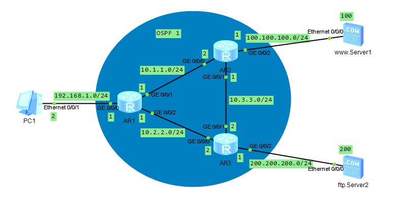
IP-адреса следующие:
PC1:
Ethernet 0/0/1:192.168.1.2/24
AR1:
GE 0/0/0:192.168.1.1/24(Заявлен ospf)
GE 0/0/1:10.1.1.1/24(Заявлен ospf)
GE 0/0/2:10.2.2.1/24(Заявлен ospf)
AR2:
GE 0/0/0:10.1.1.2/24(Заявлен ospf)
GE 0/0/1:10.3.3.1/24(Заявлен ospf)
GE 0/0/2:100.100.100.1/24(Заявлен ospf)
AR3:
GE 0/0/0:10.2.2.2/24(Заявлен ospf)
GE 0/0/1:10.3.3.2/24(Заявлен ospf)
GE 0/0/2:200.200.200.1/24(Заявлен ospf)
www.Server1:
Ethernet 0/0/0:100.100.100.100/24
ftp.Server2:
Ethernet 0/0/0:200.200.200.200/24Топология

2.2 Настройка OSPF на маршрутизаторах R1, R2 и R3
AR1:
<R2>un t m
Info: Current terminal monitor is off.
<R2>sy
Enter system view, return user view with Ctrl+Z.
[R1]ospf
[R1-ospf-1]area 0
[R1-ospf-1-area-0.0.0.0]network 192.168.1.0 0.0.0.255
[R1-ospf-1-area-0.0.0.0]network 10.1.1.0 0.0.0.255
[R1-ospf-1-area-0.0.0.0]network 10.2.2.0 0.0.0.25
[R1-ospf-1-area-0.0.0.0]dis th
[V200R003C00]
#
 area 0.0.0.0
  network 10.1.1.0 0.0.0.255
  network 10.2.2.0 0.0.0.255
  network 192.168.0.0 0.0.0.255
#
return

AR2:
<R2>un t m
Info: Current terminal monitor is off.
<R2>sy
Enter system view, return user view with Ctrl+Z.
[R2]ospf
[R2-ospf-1]area 0
[R2-ospf-1-area-0.0.0.0]network 10.1.1.0 0.0.0.255
[R2-ospf-1-area-0.0.0.0]network 10.3.3.0 0.0.0.255
[R2-ospf-1-area-0.0.0.0]network 100.100.100.0 0.0.0.255
[R2-ospf-1-area-0.0.0.0]dis th
[V200R003C00]
#
 area 0.0.0.0
  network 10.1.1.0 0.0.0.255
  network 10.3.3.0 0.0.0.255
  network 100.100.100.0 0.0.0.255
#
return

AR3:
<R3>un t m
Info: Current terminal monitor is off.
<R3>sy
Enter system view, return user view with Ctrl+Z.
[R3]ospf
[R3-ospf-1]area 0
[R3-ospf-1-area-0.0.0.0]network 10.2.2.0 0.0.0.255
[R3-ospf-1-area-0.0.0.0]network 10.3.3.0 0.0.0.255
[R3-ospf-1-area-0.0.0.0]network 200.200.200.0 0.0.0.255
[R3-ospf-1-area-0.0.0.0]dis th
[V200R003C00]
#
 area 0.0.0.0
  network 10.2.2.0 0.0.0.255
  network 10.3.3.0 0.0.0.255
  network 200.200.200.0 0.0.0.255
#
return
Проверьте, совместима ли вся сеть
2.3 Настройка контроля доступа к трафику
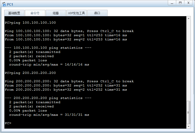
Следуйте по маршруту от ПК1 до www.Server1

Проследите путь от ПК2 до ftp.Server2
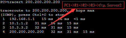
Запрос:
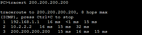
Маршрут от ПК1 к ftp.Server2 изначально был PC1-> R1-> R2-> R3-> ftp.Server2 изменен на PC1-> R1-> R3-> ftp.Server2
Конфигурация следующая:
# Только нужно настроить политику на R1
# Расширенная конфигурация политики acl
[R1]acl 3000
[R1-acl-adv-3000]rule permit ip destination 200.200.200.200 0
[R1-acl-adv-3000]dis th
[V200R003C00]
#
acl number 3000
 rule 5 permit ip destination 200.200.200.200 0
#
return
[R1-acl-adv-3000]qu

# Конфигурация классификации потока
[R1]traffic classifier c1
[R1-classifier-c1]if-match acl 3000
[R1-classifier-c1]dis th
[V200R003C00]
#
traffic classifier c1 operator or
 if-match acl 3000
#
return
[R1-classifier-c1]qu

# Конфигурация поведения трафика
[R1]traffic behavior b1
[R1-behavior-b1]redirect ip-nexthop 10.2.2.2  # Перенаправить на
[R1-behavior-b1]qu

# Разработайте стратегию движения
[R1]traffic policy p1
[R1-trafficpolicy-p1]classifier c1 behavior b1
[R1-trafficpolicy-p1]qu

# Стратегия применения
[R1]int g0/0/0
[R1-GigabitEthernet0/0/0]traffic-policy p1 inbound  # Необходимо установить направление импорта
[R1-GigabitEthernet0/0/0]qu
[R1]dis traffic policy user-defined
  User Defined Traffic Policy Information:
  Policy: p1
   Classifier: c1
    Operator: OR
     Behavior: b1
      Redirect:
        Redirect ip-nexthop 10.2.2.2

[R1]
контрольная работа
3 Token bucket и конфигурация Qos
Алгоритм token bucket — это наиболее часто используемый алгоритм для формирования сетевого трафика (Traffic Shaping) и ограничения скорости (Rate Limiting). Обычно алгоритм token bucket используется для управления объемом данных, отправляемых в сеть, и позволяет отправлять пакетные данные. Это можно сравнить с выпуском карт (жетонов) для автомагистралей. Чем больше выпущено карт, тем более загружено шоссе. Следовательно, необходимо ввести некоторые ограничения скорости, то есть выдавать меньше карт (жетонов).
Необходимо понимать следующие понятия существительных:
CIR: (Подтвержденная скорость передачи информации, подтвержденная скорость передачи информации). Единица измерения — кбит / с (в битах), скорость передачи в секунду. Например, установите 500 Кбит / с. Каждые 8 бит = 1 байт 1 кбит / с = 1024 бит
PIR(Пиковая информационная скорость, пиковая информационная скорость): максимальная скорость, разрешенная для передачи или пересылки пакетов; единица измерения — бит
CBS: (Committed Burst Size): подтвержденный размер пакета. Размер пакета, емкость сегмента маркера, является максимальным размером трафика, разрешенным для каждого пакета. Установленный размер пакета должен быть больше максимальной длины сообщения. Единица измерения — байт (байт).
PBS: (Максимальный размер пакета): максимальный размер пакета
EBS: (Превышение размера пакета, превышающее размер пакета): то есть избыточный пакетный трафик, который может быть передан мгновенно.
Параметры PIR и PBS доступны только в коммутаторе.
зеленый (успешно прошел) <CIR <желтый (ожидание очереди) <PIR <красный (сбросить)
3.1 конфигурация трафика
Требуемый предел скорости: 10M для CIR, 2000000 для CBS, 4000000 для PBS.
Здесь следует отметить, что только одна стратегия может быть настроена для одного интерфейса устройства, то есть только одна стратегия может быть зарезервирована для интерфейса GE0 / 0/0 маршрутизатора R1, поэтому вам необходимо отменить предыдущую стратегию.
# Расширенная конфигурация политики acl
[R1]acl 3001
[R1-acl-adv-3001]rule permit ip destination 100.100.100.100 0
[R1-acl-adv-3001]qu

# Конфигурация классификации потока
[R1]traffic classifier c2
[R1-classifier-c2]if-match acl 3001
[R1-classifier-c2]qu

# Конфигурация поведения трафика
[R1]traffic behavior b2
[R1-behavior-b2]car cir 10000 cbs 2000000 pbs 4000000 green pass yellow pass remark-dscp 20 red discard   # автомобиль - ограничение скорости
[R1-behavior-b2]qu

# Разработайте стратегию движения
[R1]traffic policy p2
[R1-trafficpolicy-p2]classifier c2 behavior b2
[R1-trafficpolicy-p2]qu

# Стратегия применения
[R1]int g0/0/0
[R1-GigabitEthernet0/0/0]dis th
[V200R003C00]
#
interface GigabitEthernet0/0/0
 ip address 192.168.1.1 255.255.255.0
 traffic-policy p1 inbound
#
return
[R1-GigabitEthernet0/0/0]undo traffic-policy inbound   # Отключить предыдущую стратегию
[R1-GigabitEthernet0/0/0]traffic-policy p2 inbound
[R1-GigabitEthernet0/0/0]qu
[R1]dis traffic policy user-defined
  User Defined Traffic Policy Information:
  Policy: p2
   Classifier: c2
    Operator: OR
     Behavior: b2
      Committed Access Rate:
        CIR 10000 (Kbps), PIR 0 (Kbps), CBS 2000000 (byte), PBS 4000000 (byte)
        Color Mode: color Blind
        Conform Action: pass
        Yellow  Action: remark dscp 20 and pass
        Exceed  Action: discard

  Policy: p1
   Classifier: c1
    Operator: OR
     Behavior: b1
      Redirect:
        Redirect ip-nexthop 10.2.2.2

[R1]
3.2 Конфигурация Qos
# qos относительно прост, всего одна команда
[R1-GigabitEthernet0/0/0]qos car inbound acl 3001 cir 10000 cbs 2000000 pbs 4000000 green pass yellow pass remark-dscp 20 red discard
[R1-GigabitEthernet0/0/0]dis th
[V200R003C00]
#
interface GigabitEthernet0/0/0
 ip address 192.168.1.1 255.255.255.0
 qos car inbound acl 3001 cir 10000 cbs 2000000 pbs 4000000 green pass yellow pa
ss remark-dscp af22 red discard
 traffic-policy p2 inbound
#
return
[R1-GigabitEthernet0/0/0]Команды вводим из system view:
qos pq
traffic classifier dscp-be operator and
if-match ip-precedence 0 1
traffic classifier dscp-af2 operator and
if-match ip-precedence 2
traffic classifier dscp-af3 operator and
if-match ip-precedence 3
traffic classifier dscp-af4 operator and
if-match ip-precedence 4
traffic classifier dscp-ef operator and
if-match ip-precedence 5
traffic classifier dscp-cs6 operator and
if-match ip-precedence 6 7
traffic behavior dscp-be
remark 8021p 0
traffic behavior dscp-af2
remark 8021p 2
traffic behavior dscp-af3
remark 8021p 3
traffic behavior dscp-af4
remark 8021p 4
traffic behavior dscp-ef
remark 8021p 5
traffic behavior dscp-cs6
remark 8021p 6
traffic policy dscp-cos
classifier dscp-be behavior dscp-be
classifier dscp-af2 behavior dscp-af2
classifier dscp-af3 behavior dscp-af3
classifier dscp-af4 behavior dscp-af4
classifier dscp-ef behavior dscp-ef
classifier dscp-cs6 behavior dscp-cs6
На аплинках прописываем:
traffic-policy dscp-cos inbound
trust 8021p
Запись опубликована в рубрике Без рубрики. Добавьте в закладки постоянную ссылку.