In this DHCP Cisco Packet Tracer router example, we will focus on DHCP Configuration in Cisco Packet Tracer. In other words, we will see how to configure a DHCP Server with Packet Tracer Router. Before start up I want to give some basic information about DHCP.
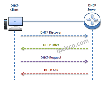
As you know DHCP uses UDP 67 and UDP 68 ports. It has a messaging system for the communication between DHCP Server and DHCP Client. These messaging system’s messages and their types are mentined below:
- DHCP Discover (broadcast)
- DHCP Offer(broadcast)
- DHCP Request (broadcast)
- DHCP Ack (broadcast)
- DHCP Nak (unicast)
- DHCP Release (unicast)
- DHCP Decline (unicast)
- DHCP Inform (unicast)
 DHCP Messages
You can Reach All Cisco Packet Tracer Labs and DOWNLOAD the Packet Tracer Examples with .pkt format.
You can DOWNLOAD this lessons Packet Tracer Example with .pkt format HERE.
- Firstly, a client sends a broadcast “DHCP Discovery” message that mentions that it need an ip address.
- Then, the DHCP servers reply with configuration offers to the client by “DHCP Offer” unicast message
- After that DHCP client sends a broadcast “DHCP Request” message to the network with the “Transaction ID” of the first DHCP Server that send Offer. The other servers understand that client wants to use the server that has the related “Transaction ID”.
- Lastly, the Server sends a unicast “Acknowledgement” message to the client that mentions the ip assignment is successfully done or it send a refuse messaged named “DHCP-NACK”.
To configure a Packet Tracer Router ’s DHCP, we must follow some basic steps. For this configuration the important point is broadcast domains. If we have only one broadcast domain in our topology, our work is simpler, else we must get help from “ip-helper address” command.
What is ip helper address command? Ip helper address command is the command that helps us to convince the router and make it pass the broadcast packets.
Now, let’s go to our two different configuration topology and see how to configure a server in packet tracer for DHCP, how to configure a DHCP Server in packet tracer.
Table of Contents
DHCP Packet Tracer Config For One Broadcast Domain
Our one broadcast domain topology is like below. There is a router that will carry our DHCP server role beside its routing functionalities. And there is a switch for PCs.
 DHCP Example Topology (One Broadcast Domain)
Firstly, let’s see How to Configure a DHCP Server on a Packet Tracer Router for One Broadcast Domain. For this first case of our DHCP Cisco packet tracer example, the One Broadcast Domain topology that we will use, is like below. There is a router that will carry out Server role beside its routing functionalities. And there is a switch for PCs.
On routerA, firstly we will give an ip address to the router interface that is connected to the switch.Secondly that we will create a DHCP pool named IPD. In this pool we will mention ip addresses that will be given to the DHCP clients. After that we will assign the router’s interface address as a default-router address for clients. And in the last part, we will exclude some addresses with “ip dhcp excluded address” command, that we don’t want to use during this dynamic ip assignments. With “ip dhcp excluded address” command, the mentined addresses will not used in the pool.
RouterA# config terminal
RouterA(config)# interface fastEthernet 1/0
RouterA(config-if)# ip address 192.168.10.1 255.255.255.0
RouterA(config-if)# no shut

%LINK-5-CHANGED: Interface FastEthernet1/0, changed state to up
%LINEPROTO-5-UPDOWN: Line protocol on Interface FastEthernet1/0, changed state to up<
RouterA(config-if)# exit
RouterA(config)# ip dhcp pool IPD
RouterA(dhcp-config)# network 192.168.10.0 255.255.255.0
RouterA(dhcp-config)# default-router 192.168.10.1
RouterA(dhcp-config)# exit
RouterA(config)# ip dhcp excluded-address 192.168.10.1 192.168.10.10
RouterA(config)# ip dhcp excluded-address 192.168.10.12 192.168.10.14
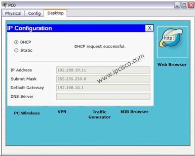
After this configuration, when we check the ip address of PC0, we will see the ip address 192.168.10.11 . Because it is the first available address in DHCP pool.
 We can also check the pool information with Cisco “show ip dhcp pool” command.
Packet Tracer DHCP Config For Multiple Broadcast Domains
Our second case is how to enable DHCP on router for multiple broadcast domains. In our second Cisco packet tracer example, we will use ip helper, cisco command “ip helper-address“. So, what is ip helper address?
Many CCNAs learn that routers do not pass broadcasts. But progress in CCIE, network engineers learn that it is not true. Because you can pass broadcast traffic for many protocols as DHCP by “ip-helper address” command. Here we will refer only the broadcast of DHCP requests. We can use a router as a DHCP Server again, but I use a separate DHCP Server instead of router in this topology.
") DHCP Example Topology (Multiple Broadcast Domains)
DHCP Example Topology (Multiple Broadcast Domains)
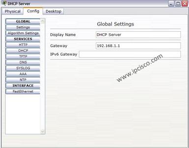
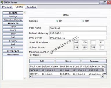
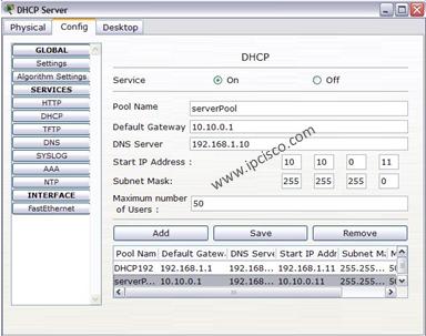
In the first place we will configure the DHCP Server for its DHCP pools and its ip configuration. The ip address is 192.168.1.10 and the default gateway will be the routers interface’s ip address that is face to DHCP server.
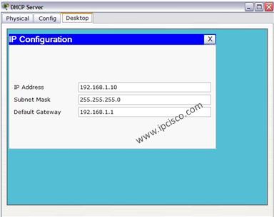
For the subnets 192.168.1.0 and 10.10.0.0 there must be two DHCP pool.The below screenshot is showing how these assignments will be done in DHCP Server.
In the Packet Tracer router the following configuration will be done for two different subnet DHCP achivement:
RouterC # config terminal
RouterC(config)# interface fa0/0
RouterC(config-if)# ip address 10.10.0.1 255.255.255.0
RouterC(config-if)# ip helper-address 192.168.1.10
RouterC(config-if)# no shutdown
RouterC(config-if)# exit
RouterC(config)# interface fa1/0
RouterC(config-if)# ip address 192.168.1.1 255.255.255.0
RouterC(config-if)# ip helper-address 192.168.1.10
RouterC(config-if)# no shutdown
RouterC(config-if)# end
RouterC# copy run start
After this configuration, we can try dynamic ip assignment on PC by selecting the dynamic option on ip configuration screen like below.
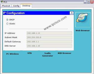
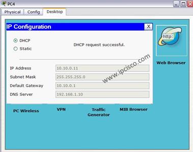
As you can seee, our PCs get their IP configuration from DHCP Server. The IP assignment is done automatically.

DHCP Messages
Packet Tracer Router Configuration Basics
Here, I would like to give you some information about how to configure a Cisco router on Packet Tracer basically. This is not a part of DHCP Configuration, but they are essentials for router configuration. So, here, we will learn how to set our laptop to connect a router, how to change a router’s name, how to set passwords on the Cisco routers, how to set console Access and basic static routing configuration step by step.
Laptop Configuration to Connect a Router
In Cisco Packet Tracer, you can directly click routers and connect them. But if you would like to do this via Console connection with a laptop with console cable as in real world, you can do it with a laptop and router. To do this, you need to set laptop terminal software setting and then a console cable to connect laptop and router.
When you click laptop on cisco packet tracer, you will see some tabs. In the desktop tab, there is a terminal configuration. When you click it, you will see the terminal settings. If you would like to connect to a router, you should set the settings as below:
Bits Per Second: 9600
Data Bits: 8
Parity : None
Stop Bits : 1
Flow Control : None
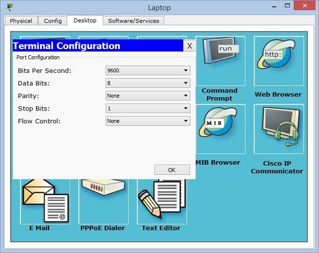
After setting these configurations, you will be ready to connect your router in packet tracer.
How to start configuration on a Cisco router?
In all routers, there are special configuration commands to start the router configuration. In Cisco routers this is also a standard. To start to configure a router on packet tracer, we should use firstly “enable” command. This will give us an administrator privilege and then we will use “configure terminal” to start our packet tracer router configuration. You can use this long version or you can use even “conf t” to do this.
Router> enable

Router# configure terminal
Enter configuration commands, one per line.  End with CNTL/Z.

Router(config) #
How to Configure Router Name?
All routers have a default name. But generally, this name is changed to have more meaningful router names. These router names can show the location of a router, its level, importance etc. With one or more word, we can give a special name to the routers on packet tracer.
To give a router name to a Cisco router on packet tracer, we use “hostname” commands. We can use this command in configuration mode of Cisco routers. Here, we can set our router’s name as XYZ
Router(config)# hostname XYZ
How to Configure Enable Secret Password?
To secure our router, firstly we should give a password to this router. There are different passwords used in Cisco routers. One of the basic passwords used in routers is “enable password”. This is the password that keeps the password as clear text. But there is also another password called “enable secret password”. This password keeps passwords with MD5 and it is more secure. You can see the value of enable password clearly in configuration, but you can not see enable secret password in configuration.
Here, let’s configure our enable secret password as abc123.
XYZ (config)# enable secret password abc123
By the way the command to encrypt passwords is “service password-encryption”. We will use this command to encrypt our passwords.
XYZ (config)# service password-encryption
How to Configure Console Access on Cisco Routers?
Console connection is need to be done before your connection. It is the basic router configuration that is required to connect to the router with a laptop.
We use “line console 0” command to access console configuration. We will determine a password, let’s do it as abcdef. After that we will use “login” keyword.
XYZ (config)# line console 0

XYZ (config-line) # password abcdef

XYZ (config-line) # login
Beside this basic console configuration, there are also some other configuration steps under this console access that will help you during our packet tracer router configuration a lot. These commands are:
- logging synchronous
- exec-timeout
- history size
With logging synchronous, we can set console synchronization to avoid command corruption. If we do not use this command, router can print some outputs during we are entering the commands and after a while this can be annoying.
XYZ (config-line) # logging synchronous
Exec timeout is the command that is used to adjust router timeout. This can be set with minutes and seconds. If you do not want any timeout, you can use 0 with this command. Here, we will use 3 minutes 30 seconds. After this period, if there is no action, router will go to the timeout. By the way the default timeout time is 10 minutes for Cisco routers.
XYZ (config-line) # exec-timeout 3 30
The last command is related with the command history. We can set the last remembered commands with history command. Here, we will set is as 20 commands.
XYZ (config-line) # history 20
How to Set Interface IP Addresses on Cisco Routers?
One of the most important and mostly done configuration is interface configurations on the routers. So, how to give an ip address and activate an interface of a Cisco router? We will use “ip address” command with the name of the interface on the routers. Here, let’s configure GigabitEthernet 0/0 of the router with the ip address 192.168.0.5/24.
XYZ (config) # interface GigabitEthernet 0/0
XYZ (config-if) # ip address 192.168.0.5 255.255.255.0
XYZ (config-if) # no shutdown
All the interfaces of the routers are shutdown by default. So, to open these ports, we should use “no shutdown” command.
After this configuration, our port can be up or down according to the other end. If there is no problem at the other end and there is configuration, then our port will be up.
How to Configure Static Routing on Cisco Routers?
Static Routing is the simplest and most used routing type on routers. Sometimes we need to use static routing in packet tracer router configurations. So, here, we will see how to configure static routing basically.
For static routing we will use “ip route” command with the destination network, subnet mask and the gateway that we will go firstly to access this network. Think about that, we should access 10.0.0.0/24 network and our gateway to access this network is 172.16.0.1. So, our static routing configuration will be like below:
XYZ (configf) # ip route 10.0.0.0 255.255.255.0 172.16.0.1
Basic Packet Tracer Router Verification Commands
After basic configurations, you can check your configurations with basic router verification commands. Some of these commands are given below:
- show startup-config
- show running-config
- show interfaces
- show ip route
show startup-config shows the beginning configuration that is stored in NVRAM.
show running-config shows current configuration. It is stored in RAM.
With show interfaces command, you can check the status and the configurations of the interfaces.
With show ip route command, you can see the routing information both static routing and dynamic routing.
There are many other show commands used in routers. You will be familiar with all of these with more practice on Cisco Packet Tracer. In the following lessons, we will see all these commands one by one.

Hello and welcome! This tutorial will guide you on how to configure a DHCP server both on a router and on a generic server in Cisco Packet Tracer. In both cases, configuration is simple as long as you have a basic knowledge of IP addressing. On to it then!
Configuring DHCP server on a Router.
- Build the network topology:

2. On the router, configure interface fa0/0 to act as the default gateway for our LAN.
Router>enable
Router#config terminal
Router(config)#int fa0/0
Router(config-if)#ip add 192.168.1.1 255.255.255.0
Router(config-if)#no shutdown
Router(config-if)#exit
3. Configure DHCP server on the Router. In the server we will define a DHCP pool of IP addresses to be assigned to hosts, a Default gateway for the LAN and a DNS Server.
Router(config)#
Router(config)#ip dhcp pool MY_LAN
Router(dhcp-config)#network 192.168.1.0 255.255.255.0
Router(dhcp-config)#default-router 192.168.1.1
Router(dhcp-config)#dns-server 192.168.1.10
We can add ip dhcp excluded-address command to our configuration so as to configure the router to exclude addresses 192.168.1.1 through 192.168.1.10 when assigning addresses to clients. The ip dhcp excluded-address command may be used to reserve addresses that are statically assigned to key hosts.
So add the above command under the global configuration mode.
Router(config)#ip dhcp excluded-address 192.168.1.1 192.168.1.10
4. Now go to every PC and on their IP configuration tabs, enable DHCP. Every PC should be able to obtain an IP address, default gateway and DNS server, as defined in step 2.
For example, to enable DHCP on PC1:
Click PC1->Desktop->IP configuration. Then enable DHCP:

Do this for the other PCs.
You can test the configuration by pinging PC2 from PC1. Ping should succeed.
It’s that simple!
Now let’s do the same thing using a Generic server in place of a router:
Configuring DHCP service on a generic server in Packet Tracer.
1. Build the network topology in packet tracer

2. Configure static IP address on the server (192.168.1.2/24).
3. Now configure DHCP service on the generic server.
To do this, click on the server, then click on Services tab. You will pick DHCP on the menu. Then proceed to define the DHCP network parameters as follows:
Pool name: MY_LAN
Default Gateway: 192.168.1.1
DNS Server: 192.168.1.2
Start IP Address: 192.168.1.0
Subnet Mask: 255.255.255.0
Maximum Number of users: 256
Click on add then Save.The DHCP entry is included in the list.
Here are the configurations on the server:

Once you’ve configured everything, turn ON the DHCP service.
4. Finally, enable DHCP configuration on each PC. The three PCs should get automatically configured.
As an example, here is the DHCP configuration on PC1:

Addendum: You can define a DHCP server on one broadcast domain to serve hosts in a different broadcast domain. If you want to do this, then you should consider using ip helper-address command. To learn more about this, you can read my article on IP helper address configuration.
Success! Success!
Hope you found this post helpful. Comment to help improve it.
You may also like to read:
- Configuring DHCPv6 (both stateless and stateful) in Packet Tracer.
- Basic IPv6 configuration in Packet Tracer.
- DNS server configuration in Packet Tracer.
- HTTP server configuration in Packet Tracer.
- Mail server configuration in Packet Tracer.
Pre-requisite : Dynamic Host Configuration Protocol (DHCP), Basics of Wi-Fi.
DHCP is based on a client-server model, based on discovers, offers, requests, and ACKs. The DHCP port number for the server is 67 and for the client is 68. This is a client/server protocol using UDP services. IP addresses are assigned from a pool of addresses. In DHCP, clients and servers exchange four main DHCP messages to establish a connection. Also called the DORA process, there are eight DHCP messages in the process.
Configure DHCP on Wireless Router:
Step 1: Create the topology in CPT as shown in the image below :

- From the bottom toolbar, click on ‘End Devices’ and select ‘PC’ and then drag it to the workspace.

- Now select ‘Laptop’ and drag it to the workspace.
- From the bottom toolbar, click on ‘Network Devices’ and under ‘Wireless Devices’, select “Home Router” and drag it to the workspace.

Step 2: Configure DHCP on Home-Router-PT-AC :
- Click on the Home Router device.
- A dialogue box will appear then click on “Config” tab.
- From the side menu bar, click on “LAN” and configure LAN settings as shown in the image below :Cl

- Click on “GUI” tab and configure the basic setup as shown in the image below :

Step 3: Click on the PC and under physical tab, change the module of the PC as follows :
- Turn off the PC.
- Change the default module with the WMP300N module which is a 2.4 GHz wireless interface for connecting to wireless network.

Step 4: Click on Laptop and under physical tab, change the module of the Laptop as follows :
- Turn off the Laptop.
- Change the default module with the WPC300N module which is a 2.4 GHz wireless interface for connecting to wireless network.

Step 5: After completing the above steps, the end devices (PC and Laptop) will automatically connect to the wireless network configured on the Home router device and request for the IPv4 address and the topology will look like this :

Step 6: Verify IP configuration and connectivity throughout the topology :
- Click on the PC and under the “Desktop” tab click on “Command Prompt” and check IP configuration with the command :
C:\>ipconfig

- Now, check the connectivity with other devices in the topology by pinging them :
C:\>ping 192.168.1.1
C:\>ping 192.168.1.101

Simulation Result:

- Click on the Laptop and under the “Desktop” tab click on “Command Prompt” and check IP configuration with the command :
C:\>ipconfig

C:\>ping 192.168.1.1
C:\>ping 192.168.1.100

Simulation Result:

Last Updated :
13 Nov, 2022
Like Article
Save Article
Протокол DHCP позволяет производить автоматическую настройку сетевых устройств. Настройка DHCP сервера на маршрутизаторе выгодна тем, что позволяет по максимум задействовать работающий маршрутизатор, повесив на него максимальное количество функционала (интернет, NAT, DHCP и т.п.). DCHP позволит маршрутизатору автоматически настраивать на клиентах следующие основные параметры:
- IP адрес
- Основной шлюз
- Маска подсети
- DNS сервера
- Имя домена
Ниже мы приводим для вас сразу несколько разных инструкций по настройке DHCP на оборудовании Cisco.
СОДЕРЖАНИЕ:
- Видеоурок по работе с Cisco Packet Tracer. Курс молодого бойца по настройке DHCP
- Настройка централизованного DHCP сервера с помощью Cisco Packet Tracer
- Листинг команд настройки маршрутизатора R1, на котором «поднят» DHCP сервер
- Настройка DHCP сервера на маршрутизаторе Cisco, возможные причины неработоспособности сети
- Полезные команды настройке DHCP Cisco
Видеоурок по работе с Cisco Packet Tracer. Курс молодого бойца по настройке DHCP
Настройка централизованного DHCP сервера с помощью Cisco Packet Tracer
В этой видео инструкции рассматривается процесс настройки централизованного DHCP сервера в программе Cisco Packet Tracer.
Показано:
- как настроить пулы динамических IP адресов для различных сегментов локальной сети,
- как настроить рабочую станцию на получение динамического IP адреса,
- как проверить наличие получения динамического IP адреса рабочей станцией.
Новые команды для настройки маршрутизатора для получения пула динамических IP адресов у централизованного DHCP сервера.
Для примера рассматривается роутер R1
Настройки производятся в режиме глобальной конфигурации:
R1(config)#interface fastEthernet 0/1 — заходим в настройки интерфейса к которому подключен компьютер получающий динамический IP адрес
R1(config-if)#ip helper-address 192.168.30.11 указывается IP адрес централизованного DHCP сервера.
R1(config-if)#do wr
Building configuration…
Листинг команд настройки маршрутизатора R1, на котором «поднят» DHCP сервер, следующий:
R1#conf t
R1(config)#interface Ethernet 0/1/0
R1(config-if)#ip address 172.33.56.1 255.255.255.0
R1(config-if)#no sh
R1(config-if)#exit
R1(config)#ip dhcp excluded-address 172.33.56.1
R1(config)#ip dhcp excluded-address 172.33.56.254
R1(config)#ip dhcp pool R1SW6
R1(dhcp-config)#default-router 172.33.56.1
R1(dhcp-config)#network 172.33.56.0 255.255.255.0
R1(dhcp-config)#dns-server 192.168.40.11
R1(dhcp-config)#do wr
Building configuration…
[OK]
R1(dhcp-config)#exit
R1(config)#do sh ip prot
Routing Protocol is «bgp 1»
Outgoing update filter list for all interfaces is not set
Incoming update filter list for all interfaces is not set
R1(config)#router bgp 1
R1(config-router)#do sh ip route
(фрагмент ответа)
172.33.0.0/24 is subnetted, 1 subnets
C 172.33.56.0 is directly connected, Ethernet0/1/0
R1(config-router)#network 172.33.56.0 mask 255.255.255.0
R1(config-router)#do wr
Настройка DHCP сервера на маршрутизаторе Cisco, возможные причины неработоспособности сети
Рассматривается настройка DHCP сервера на маршрутизаторе Cisco, показаны возможные причины неработоспособности сети, связанные с работой протоколов маршрутизации и варианты устранения данных неполадок.
Полезные команды настройке DHCP Cisco
- Исключим из раздачи адрес 192.168.1.254 и адреса с 192.168.1.1 по 192.168.1.9
Router(config)# ip dhcp excluded-address 192.168.1.254
Router(config)# ip dhcp excluded-address 192.168.1.1 192.168.1.9
- Настройка DHCP пула
Настройка DHCP сервера включает в себя определение пула адресов, которые будут раздаваться. Для создания пула используется команда ip dhcp pool [название_пула]. После этого необходимо ввести две обязательные команды – network [адрес_сети][маска/длина_префикса] для указания сети из которой будут раздаваться адреса и default-router[адрес_default_gateway] для указания шлюза по умолчанию (можно ввести до 8 адресов).
- команда show ip dhcp binding показывает список всех IP адресов и сопоставленных с ними MAC адресов, которые были выданы DHCP сервером.
- команда show ip dhcp server statistics покажет статистику DHCP сервера, включая информацию об отправленных и полученных DHCP сообщениях
- Ретрансляция DHCP (DHCP RELAY)
Команда ip helper-address [адрес_DHCP-сервера] на маршрутизаторе в режиме конфигурации интерфейса укажет ему перенаправлять broadcast сообщения от DHCP клиентов уже в виде unicast к DHCP серверу, находящемуся в другой сети.
- Настройка роутера DHCP клиента
Иногда роутер сам должен получить IP адрес по DHCP, например от интернет-провайдера. Для этого нужно в режиме конфигурации интерфейса ввести команду ip address dhcp, после чего интерфейс будет пытаться получить адрес от DHCP сервера.
Introduction: How to Configure DHCP in Cisco Packet Tracer
In this tutorial we will configure IP addresses dynamically, for this will be done two examples configuring DHCP. The first configuration is through the router and the second is through a server.
I use 2 language for this instructable, the English and the Spanish.
Step 1:
Step 1: First configure the DHCP service on the router, so
we will first enable the two interfaces and place their respective IP addresses with their Subnet Mask.
To do this, the following commands will be written in global configuration for the R1 router:
Int Fa0/0
Ip address 172.16.0.1 255.255.255.0
No shutdown
Int Fa0/1
Ip address 172.16.1.1 255.255.255.0
No shutdown
Do write memory
Paso 1: De primero configuraremos el servicio DHCP en el router, para ello de primero habilitaremos las dos interfaces y le colocaremos sus respectivas direcciones IP con sus Subnet Mask.
Para ello se escribirán los siguientes comandos en configuración global para el router R1:
Int Fa0/0
Ip address 172.16.0.1 255.255.255.0
No shutdown
Int Fa0/1
Ip address 172.16.1.1 255.255.255.0
No shutdown
Do write memory
Step 2:
Step 2: Now you will proceed to enable a logical interface inside the router, this type of interfaces are very useful since these are always on if the router is on too. But it is good practice to always make sure that the logical interface is turned on.
To do this we will place the following commands in the global configuration:
Int loopback 1
Ip address 1.1.1.1 255.255.255.255
No shutdown
Paso 2: Ahora se procederá a habilitar una interfaz lógica dentro del router, este tipo de interfaces son muy útiles ya que estas siempre están encendidas media vez el router este encendido. Pero es una buena práctica siempre asegurarnos de que la interfaz lógica esta encendida. Para ello colocaremos los siguientes comandos en la configuración global:
Int loopback 1
Ip address 1.1.1.1 255.255.255.255
No shutdown
Step 3:
Step 3: To configure the DHCP you must know which network address we want to provide, which is the Subnet Mask and which is the Default Gateway on the network. As optional we can also exclude certain IP addresses to reserve them or simply because we do not want to use them and we can also configure a DNS service where we will place an address that we want, it is worth repeating that these last two configurations are optional since the DHCP service can Work perfectly well without these.
The commands to use are as follows:
Ip dhcp excluded-address 172.16.0.1 172.16.0.10
Ip dhcp pool NET1
Network 172.16.0.0 255.255.255.0
Default-router 1.1.1.1
Dns-server 8.8.8.8
Exit
Ip dhcp excluded-address 172.16.1.1 172.16.1.10
Ip dhcp pool NET2
Network 172.16.1.0 255.255.255.0
Default-router 1.1.1.1
Dns-server 8.8.8.8
Exit
Note that for the Default Gateway we will use the loopback address 1, we could also have put any address of the physical interfaces of the router R1 but for ease we will place in default-router 1.1.1.1. It should also be mentioned that the address 8.8.8.8 that was put in the DNS service is like a demonstrative purpose.
Paso 3: Para la configuración del DHCP se debe de tomar en cuenta cual es la dirección de red que queremos proporcionar, cual es la Subnet Mask y cuál es la Gateway de la red. Como opcional también podemos excluir ciertas direcciones IP para reservarlas o simplemente porque no las queremos usar y también podemos configurar un servicio DNS en donde colocaremos una dirección que nosotros deseemos, cabe repetir de que estas dos últimas configuraciones son opcionales ya que el servicio de DHCP puede funcionar perfectamente bien sin estas. Los comandos a utilizar son los siguientes:
Ip dhcp excluded-address 172.16.0.1 172.16.0.10
Ip dhcp pool NET1
Network 172.16.0.0 255.255.255.0
Default-router 1.1.1.1
Dns-server 8.8.8.8
Exit
Ip dhcp excluded-address 172.16.1.1 172.16.1.10
Ip dhcp pool NET2
Network 172.16.1.0 255.255.255.0
Default-router 1.1.1.1
Dns-server 8.8.8.8
Exit
Hay que tomar en consideración que para el Default Gateway usaremos la dirección de loopback 1, también se pudo haber puesto cualquier dirección de las interfaces físicas del router R1 pero por facilidad colocaremos en default-router 1.1.1.1. También hay que mencionar que la dirección 8.8.8.8 que se puso en el servicio DNS es como un fin demostrativo.
Step 4:
Step 4: We now need to require DCHP services on the respective physical interfaces of the router. We must be very careful that we are requiring the DHCP service in the correct interface, for this we must note that the address of the interface matches the address of the DHCP together with the subnet mask, to require the service we must use the address of the Default-router.
To prevent confusions in this step we will only configure the DHCP request on the Fa0/0 interface. The commands are:
Int Fa0/0
Ip helper-address 1.1.1.1
Paso 4: Ahora debemos de requerir los servicios de DCHP en las respectivas interfaces físicas del router. Debemos de ser muy precavidos de que estamos requiriendo el servicio DHCP en la interfaz correcta, para ello debemos de notar que la dirección de la interfaz coincida con la dirección del DHCP junto con la subnet mask, para requerir el servicio debemos de usar la dirección del default-router. Para evitar confusiones en este paso solo configuraremos la petición de DHCP en la interfaz Fa0/0. Los comandos son:
Int Fa0/0
Ip helper-address 1.1.1.1
Step 5:
Step 5: Now proceed to verify that if the IP addresses have been automatically distributed for the final devices that are connected to the Fa0/0 interface.
To do this we go to a laptop and select the IP Configuration option, then we have to click the DHCP option. It may take some time to give the address automatically but if we are sure that our configuration is fine we will not have to worry, there is a possibility that it will be late to give the address automatically, for that we can select the Static option and then DHCP again to get the IP address.
Paso 5: Ahora procederemos a verificar que si se hayan repartido automáticamente las direcciones IP para los dispositivos finales que estén conectados a la interfaz Fa0/0. Para ello entramos a una laptop y seleccionamos la opción IP Configuration, luego tenemos que darle click a la opción de DHCP. Puede tardar un cierto tiempo en dar la dirección automáticamente pero si estamos seguros de que nuestra configuración está bien no tendremos de que preocuparnos, hay una posibilidad de que se tarde para dar la dirección automáticamente, para eso podemos seleccionar la opción de Static y luego DHCP de nuevo para obtener la dirección IP.
Step 6:
Step 6: In this part we will configure the DHCP service for the Fa0/1 interface as it was done in Step 4, the commands we will use are:
Int Fa0/1
Ip helper-address 1.1.1.1
Do write memory
Paso 6: En esta parte configuraremos el servicio DHCP para la interfaz Fa0/1 así como se hizo en el Paso 4, los comandos que utilizaremos son:
Int Fa0/1
Ip helper-address 1.1.1.1
Do write memory
Step 7:
Step 7: We need to select the DHCP option on the laptops that are connected to the Fa0/1 interface as was done in Step 5.
Paso 7: Tenemos que seleccionar la opción de DHCP en las laptop que están conectadas a la interfaz Fa0/1 así como se hizo en el Paso 5.
Step 8:
Step 8: Now proceed to configure the DHCP service of the second form, in this method we have to configure it on a Server.
Paso 8: Ahora procederemos a configurar el servicio DHCP de la segunda forma, en este método tenemos que configurarlo en un Server.
Step 9:
Step 9: In this step we will configure the IP addresses for the physical interfaces. The programming will be done in the global configuration with the following commands:
Int fa0/0
Ip address 10.10.10.1 255.255.255.252
No shutdow
Int fa0/1
Ip address 172.32.0.1 255.255.255.0
No shutdow
Do write memory
Paso 9: En este paso configuraremos las direcciones IP para las interfaces físicas. La programación se hará en la configuración global con los siguientes comandos:
Int fa0/0
Ip address 10.10.10.1 255.255.255.252
No shutdow
Int fa0/1
Ip address 172.32.0.1 255.255.255.0
No shutdow
Do write memory
Step 10:
Step 10: In this step, select the server by selecting and clicking the Desktop option, then selecting IP Configuration to place an IP address together with the Subnet Mask and its default Gateway that matches the physical interface of the Router that is connected.
Paso 10: En este paso seleccionaremos el Server, para ello lo seleccionamos y le damos click a la opción de Desktop, luego seleccionamos IP Configuration para colocarle una dirección IP junto con su Subnet Mask y su Default Gateway que coincida con la interfaz física del router al que esta conectado.
Step 11:
Step 11: Now select the Services option and then the DHCP service.
Paso 11: Ahora seleccionamos la opción de Services y luego el servicio de DHCP.
Step 12:
Step 12: At this moment we have to select the option On to start the service and proceed to configure it, just like the DHCP programming on the router, it must match the network address we want to give you the service Ip addresses automatically.
We must take into account that the Default Gateway must be the Ip address of the interface where we will request the service, when we have everything configured we will click the Add button and then the Save button.
Paso 12: En este momento tenemos que seleccionar la opción On para poner en operación el servicio y procederemos a configurarlo, al igual que la programación de DHCP en el router, este debe de coincidir con la dirección de red que queremos brindarle el servicio de dar direcciones Ip de forma automática.
Hay que tomar muy en cuenta que la Default Gateway debe de ser la dirección Ip de la interfaz donde nos solicitarán el servicio, cuando tengamos todo configurado daremos click al botón de Add y luego al botón de Save.
Step 13:
Step 13: Then we will return to the configuration of the router to require the DHCP service of the Server, for this we must note that the service will be requested based on the IP address of the Server. The commands to be used will be programmed in the global configuration.
Int Fa0/1
Ip helper-address 10.10.10.2
Do write memory
Paso 13: Luego regresaremos a la configuración del router para requerir el servicio de DHCP del Server, para ello debemos de notar que se solicitará el servicio en base a la dirección IP del Server. Los comandos a utilizar se programarán en la configuración global.
Int Fa0/1
Ip helper-address 10.10.10.2
Do write memory
Step 14:
Step 14: Finally on a laptop select the option of Desktop and Ip Configuration, then select the DHCP option to receive the IP address automatically.
It should be remembered that if you do not give the address automatically you can implement the recommendations in Step 5.
Paso 14: Por último entraremos a un dispositivo final para seleccionaremos la opción de Desktop y Ip Configuration, luego seleccionaremos la opción de DHCP para recibir la dirección Ip de manera automática.
Se debe de recordar que si no da al principio la dirección de manera automática puede implementar las recomendaciones del Paso 5.