Базовая настройка маршрутизатора для CCNA и ICND. Назначение IP-адресов на интерфейсы маршрутизатора.
Предположим, что после деления сети 192.168.0.0/24 на 3 подсети A, B и C (по 100, 50, 2 хоста соответственно) мы получили такие подсети: A — 192.168.0.0/25, B — 192.168.0.128/26, C — 192.168.0.192/30.
Первый адрес подсети A надо назначить на интерфейс маршрутизатора fastethernet 0/0.
Первый адрес подсети B надо назначить на интерфейс маршрутизатора fastethernet 0/1.
Первый адрес подсети C надо назначить на интерфейс маршрутизатора serial 0/0/0. Причем на один конец кабеля (DCE) для интерфейса serial необходимо назначить clock rate (задать время для синхронизации сигнала), а для другого (DTE) этого делать не надо.
// Так я буду обозначать комментарии.
-
Устанавливаем консольное соединение через гипертерминал со следующими настройками:
- Скорость: 9600; Биты данных: 8; Четность: Нет; Стоповые биты: 1; Управление потоком: Нет;
- Router>enable//Входим в привилегированный режим.
- Router#
- Router#erase startup-config//Очищаем маршрутизатор от предыдущих настроек.
- Router#reload//Перезагружаем маршрутизатор.
- Would you like to enter the initial configuration dialog? [yes/no]: no//После перезагрузки маршрутизатора IOS спросит, надо ли настраивать маршрутизатор в режиме диалога. Откажитесь.
- Router>enable//Снова входим в привилегированный режим.
- Router#
- Router#configure terminal//входим в режим глобальной конфигурации
- Router(config)#hostname R1//даём имя маршрутизатору, в данном случае R1
- R1(config)#no ip domain-lookup//выключаем поиск DNS
- R1(config)#enable secret class//включаем пароль на вход привилегированного режима
- R1(config)#banner motd #//Настраиваем сообщение дня (message of the day). Между знаками «#» пишем сообщение.
!!!ACCESS DENIED!!!
# - R1(config)#line console 0//Входим в режим настройки консоли.
- R1(config-line)#password cisco//Назначаем пароль на вход.
- R1(config-line)#login//Включаем запрос пароля перед входом в консоль.
- R1(config-line)#exit
- R1(config)#line vty 0 4//Входим в режим настройки телнета.
- R1(config-line)#password cisco//Назначаем пароль на вход.
- R1(config-line)#login//Включаем запрос пароля перед входом с помощью телнета.
- R1(config-line)#end
- R1#show running-config//Проверяем введенные данные.
- R1#copy running-config startup-config//Сохраняем произведенную настройку в энерго-независимую память. Сейвы помогают не только геймерам
 Были случаи когда ПакетТрейсер вис и приходилось всё делать заново.
 - R1#configure terminal//снова заходим в режим глобальной конфигурации
- R1(config)#interface fastethernet 0/0//заходим в режим конфигурации интерфейса
- R1(config-if)#ip address 192.168.0.1 255.255.255.128//назначаем IP-адрес интерфейсу и маску 255.255.255.128 (эта маска является расшифровкой префикса /25)
- R1(config-if)#des Subnet A//краткое описание интерфейса
- R1(config-if)#no shutdown//включаем интерфейс
- R1(config)#interface fastethernet 0/1//заходим в режим конфигурации интерфейса
- R1(config-if)#ip address 192.168.0.129 255.255.255.192//назначаем IP-адрес интерфейсу и маску 255.255.255.128 (эта маска является расшифровкой префикса /25)
- R1(config-if)#des Subnet B//краткое описание интерфейса
- R1(config-if)#no shutdown//включаем интерфейс
- R1(config)#interface serial 0/0/0//заходим в режим конфигурации интерфейса
- R1(config-if)#ip address 192.168.0.193 255.255.255.252//назначаем IP-адрес интерфейсу и маску 255.255.255.128 (эта маска является расшифровкой префикса /25)
- R1(config-if)#des Link to R2//краткое описание интерфейса
- R1(config-if)#clock rate 64000//задаем время сигнала для синхронизации со вторым роутером. На втором роутере этого делать не надо!
- R1(config-if)#no shutdown//включаем интерфейс
- R1(config-line)#end//выходим в привилегированный режим EXEC Mode
- R1#show running-config//Проверяем введенные данные.
- R1#copy running-config startup-config//Сохраняем произведенную настройку в энерго-независимую память.

Скачать выполненное задание настройки роутера
Предлагаю скачать файл с выполненным заданием для программы эмулятора PacketTracer, открыть его и посмотреть на реализацию (пароль на консольный вход — cisco, на привилегированный режим — class).
Заметьте, что компьютер PC1 может нормально пинговать компьютер PC2, но не может пинговать PC3. Это происходит из-за не настроенной маршрутизации. А настроим мы её в следующей шпаргалке 
Настройка роутера копированием конфигурации
-
Для автоматической базовой настройки (всё, что выше) маршрутизатора выполните следующие действия:
- 1. Скопируйте текст ниже в буфер обмена: выделите всё, кликните правой кнопкой по выделенному и выберите «Копировать».
- 2. При необходимости очистите роутер от всех настроек и перезагрузите его.
- 3. Войдите в режим глобальной конфигурации и вызовите меню Гипер Терминала «Правка», а в нём «Передать главному компьютеру».
- 4. Обязательно проверьте настройки с помощью команды
show running-config - 5. При необходимости включите интерфейсы командой no shutdown из режима каждого интерфейса
qaa-engineer.ru > Cisco > Как разделить сеть на подсети с помощью маршрутизатора Cisco?
Чтобы разделить сеть на подсети с помощью маршрутизатора Cisco, следуйте следующим шагам:
1. Определите сеть, которую вы хотели бы разделить на подсети. Например, это может быть 192.168.0.0/24.
2. Определите требуемое количество подсетей, которые необходимо создать. Например, вы можете захотеть разбить сеть 192.168.0.0/24 на 4 подсети.
3. Выберите размер подсетей, которые вы создадите. Например, если вы хотите создать 4 подсети, каждая должна содержать 64 IP-адреса (это соответствует маске подсети /26).
4. Создайте подсети на маршрутизаторе Cisco, используя команду «ip address». Например, чтобы создать первую подсеть 192.168.0.0/26, выполните следующую команду:
Router(config)# interface GigabitEthernet0/0
Router(config-if)# ip address 192.168.0.1 255.255.255.192
5. Повторите шаг 4 для каждой подсети, которую вы создаете.
6. Настройте адрес шлюза по умолчанию для каждой подсети, используя команду «ip default-gateway». Например, для первой подсети 192.168.0.0/26 вы можете выполнить следующую команду:
Router(config)# ip default-gateway 192.168.0.1
7. Настройте маршрутизацию между подсетями в маршрутизаторе Cisco с помощью протокола маршрутизации или статических маршрутов. Например, вы можете добавить статический маршрут для подсети 192.168.0.64/26, чтобы доставлять трафик с этой подсети:
Router(config)# ip route 192.168.0.64 255.255.255.192 192.168.0.1
8. Проверьте настройки маршрутизатора, чтобы убедиться, что подсети настроены правильно и что трафик между подсетями проходит корректно.
Configuring IPv4 Addresses
This chapter contains information about, and instructions for configuring IPv4 addresses on interfaces that are part of a
networking device.

Note |
All further references to IPv4 addresses in this document use only IP in the text, not IPv4. |
Reference the Chapter Map here
Information About IP Addresses
Binary Numbering
IP addresses are 32 bits long. The 32 bits are divided into four octets (8-bits). A basic understanding of binary numbering
is very helpful if you are going to manage IP addresses in a network because changes in the values of the 32 bits indicate
either a different IP network address or IP host address.
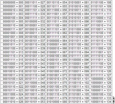
A value in binary is represented by the number (0 or 1) in each position multiplied by the number 2 to the power of the position
of the number in sequence, starting with 0 and increasing to 7, working right to left. The figure below is an example of an
8-digit binary number.

The figure below provides binary to decimal number conversion for 0 through 134.
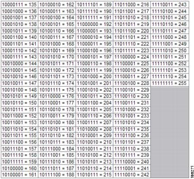
The figure below provides binary to decimal number conversion for 135 through 255.
IP Address Structure
An IP host address identifies a device to which IP packets can be sent. An IP network address identifies a specific network
segment to which one or more hosts can be connected. The following are characteristics of IP addresses:
-
IP addresses are 32 bits long
-
IP addresses are divided into four sections of one byte (octet) each
-
IP addresses are typically written in a format known as dotted decimal
The table below shows some examples of IP addresses.
|
IP Addresses in Dotted Decimal |
IP Addresses in Binary |
|---|---|
|
10.34.216.75 |
00001010.00100010.11011000.01001011 |
|
172.16.89.34 |
10101100.00010000.01011001.00100010 |
|
192.168.100.4 |
11000000.10101000.01100100.00000100 |
|
Note |
The IP addresses in the table above are from RFC 1918, |
IP addresses are further subdivided into two sections known as network and host. The division is accomplished by arbitrarily
ranges of IP addresses to classes. For more information see RFC 791 Internet Protocol at
http://www.ietf.org/rfc/rfc0791.txt .
IP Address Classes
In order to provide some structure to the way IP addresses are assigned, IP addresses are grouped into classes. Each class
has a range of IP addresses. The range of IP addresses in each class is determined by the number of bits allocated to the
network section of the 32-bit IP address. The number of bits allocated to the network section is represented by a mask written
in dotted decimal or with the abbreviation /n where
n = the numbers of bits in the mask.
The table below lists ranges of IP addresses by class and the masks associated with each class. The digits in bold indicate
the network section of the IP address for each class. The remaining digits are available for host IP addresses. For example,
IP address 10.90.45.1 with a mask of 255.0.0.0 is broken down into a network IP address of 10.0.0.0 and a host IP address
of 0.90.45.1.
|
Class |
Range |
|---|---|
|
A (range/mask in dotted decimal) |
|
|
A (range in binary) |
|
|
A (mask in binary) |
11111111.00000000.00000000.00000000/8 |
|
B (range/mask in dotted decimal) |
|
|
B (range in binary) |
|
|
B (mask in binary) |
|
|
C (range/mask in dotted decimal) |
|
|
C (range in binary) |
|
|
C (mask in binary) |
11111111.11111111.11111111.0000000/24 |
|
D1 (range/mask in dotted decimal) |
|
|
D (range in binary) |
|
|
D (mask in binary) |
11111111.11111111.11111111.11111111/32 |
|
E2 (range/mask in dotted decimal) |
|
|
E (range in binary) |
|
|
E (mask in binary) |
11111111.11111111.11111111.11111111/32 |
|
Note |
Some IP addresses in these ranges are reserved for special uses. For more information refer to RFC 3330, |
When a digit that falls within the network mask changes from 1 to 0 or 0 to 1 the network address is changed. For example,
if you change 10101100.00010000.01011001.00100010/16 to 10101100.00110000.01011001.00100010/16 you have changed the network
address from 172.16.89.34/16 to 172.48.89.34/16.
When a digit that falls outside the network mask changes from 1 to 0 or 0 to 1 the host address is changed. For example,
if you change 10101100.00010000.01011001.00100010/16 to 10101100.00010000.01011001.00100011/16 you have changed the host address
from 172.16.89.34/16 to 172.16.89.35/16.
Each class of IP address supports a specific range of IP network addresses and IP host addresses. The range of IP network
addresses available for each class is determined with the formula 2 to the power of the number of available bits. In the case
of class A addresses, the value of the first bit in the 1st octet (as shown in the table above) is fixed at 0. This leaves
7 bits for creating additional network addresses. Therefore there are 128 IP network addresses available for class A (27 =
128).
The number of IP host addresses available for an IP address class is determined by the formula 2 to the power of the number
of available bits minus 2. There are 24 bits available in a class A addresses for IP host addresses. Therefore there are 16,777,214
IP hosts addresses available for class A ((224) — 2 = 16,777,214)).
|
Note |
The 2 is subtracted because there are 2 IP addresses that cannot be used for a host. The all 0’s host address cannot be used |
The table below shows the network and host addresses available for each class of IP address.
|
Class |
Network Addresses |
Host Addresses |
|---|---|---|
|
A |
128 |
16,777,214 |
|
B |
16,3843 |
65534 |
|
C |
2,097,1524 |
254 |
.
IP Network Subnetting
The arbitrary subdivision of network and host bits in IP address classes resulted in an inefficient allocation of IP space.
For example, if your network has 16 separate physical segments you will need 16 IP network addresses. If you use 16 class
B IP network addresses, you would be able to support 65,534 hosts on each of the physical segments. Your total number of supported
host IP addresses is 1,048,544 (16 * 65,534 = 1,048,544). Very few network technologies can scale to having 65,534 hosts on
a single network segment. Very few companies need 1,048,544 IP host addresses. This problem required the development of a
new strategy that permitted the subdivision of IP network addresses into smaller groupings of IP subnetwork addresses. This
strategy is known as subnetting.
If your network has 16 separate physical segments you will need 16 IP subnetwork addresses. This can be accomplished with
one class B IP address. For example, start with the class B IP address of 172.16.0.0 you can reserve 4 bits from the third
octet as subnet bits. This gives you 16 subnet IP addresses 24 = 16. The table below shows the IP subnets for 172.16.0.0/20.
|
Number |
IP Subnet Addresses in Dotted Decimal |
IP Subnet Addresses in Binary |
|---|---|---|
|
05 |
172.16.0.0 |
10101100.00010000.00000000.00000000 |
|
1 |
172.16.16.0 |
10101100.00010000.00010000.00000000 |
|
2 |
172.16.32.0 |
10101100.00010000.00100000.00000000 |
|
3 |
172.16.48.0 |
10101100.00010000.00110000.00000000 |
|
4 |
172.16.64.0 |
10101100.00010000.01000000.00000000 |
|
5 |
172.16.80.0 |
10101100.00010000.01010000.00000000 |
|
6 |
172.16.96.0 |
10101100.00010000.01100000.00000000 |
|
7 |
172.16.112.0 |
10101100.00010000.01110000.00000000 |
|
8 |
172.16.128.0 |
10101100.00010000.10000000.00000000 |
|
9 |
172.16.144.0 |
10101100.00010000.10010000.00000000 |
|
10 |
172.16.160.0 |
10101100.00010000.10100000.00000000 |
|
11 |
172.16.176.0 |
10101100.00010000.10110000.00000000 |
|
12 |
172.16.192.0 |
10101100.00010000.11000000.00000000 |
|
13 |
172.16.208.0 |
10101100.00010000.11010000.00000000 |
|
14 |
172.16.224.0 |
10101100.00010000.11100000.00000000 |
|
15 |
172.16.240.0 |
10101100.00010000.11110000.00000000 |
address and must be used carefully.
When a digit that falls within the subnetwork (subnet) mask changes from 1 to 0 or 0 to 1 the subnetwork address is changed.
For example, if you change 10101100.00010000.01011001.00100010/20 to 10101100.00010000.01111001.00100010/20 you have changed
the network address from 172.16.89.34/20 to 172.16.121.34/20.
When a digit that falls outside the subnet mask changes from 1 to 0 or 0 to 1 the host address is changed. For example, if
you change 10101100.00010000.01011001.00100010/20 to 10101100.00010000.01011001.00100011/20 you have changed the host address
from 172.16.89.34/20 to 172.16.89.35/20.

Timesaver |
To avoid having to do manual IP network, subnetwork, and host calculations, use one of the free IP subnet calculators available |
Some people get confused about the terms network address and subnet or subnetwork addresses and when to use them. In the
most general sense the term network address means “the IP address that routers use to route traffic to a specific network
segment so that the intended destination IP host on that segment can receive it”. Therefore the term network address can apply
to both non-subnetted and subnetted IP network addresses. When you are troubleshooting problems with forwarding traffic from
a router to a specific IP network address that is actually a subnetted network address, it can help to be more specific by
referring to the destination network address as a subnet network address because some routing protocols handle advertising
subnet network routes differently from network routes. For example, the default behavior for RIP v2 is to automatically summarize
the subnet network addresses that it is connected to their non-subnetted network addresses (172.16.32.0/24 is advertised by
RIP v2 as 172.16.0.0/16) when sending routing updates to other routers. Therefore the other routers might have knowledge of
the IP network addresses in the network, but not the subnetted network addresses of the IP network addresses.

Tip |
The term IP address space is sometimes used to refer to a range of IP addresses. For example, “We have to allocate a new |
IP Network Address Assignments
Routers keep track of IP network addresses to understand the network IP topology (layer 3 of the OSI reference model) of
the network to ensure that IP traffic can be routed properly. In order for the routers to understand the network layer (IP)
topology, every individual physical network segment that is separated from any other physical network segment by a router
must have a unique IP network address.
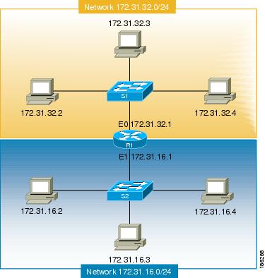
The figure below shows an example of a simple network with correctly configured IP network addresses. The routing table in
R1 looks like the table below.
|
Interface Ethernet 0 |
Interface Ethernet 1 |
|---|---|
|
172.31.32.0/24 (Connected) |
172.31.16.0/24 (Connected) |
The figure below shows an example of a simple network with incorrectly configured IP network addresses. The routing table
in R1 looks like the table below. If the PC with IP address 172.31.32.3 attempts to send IP traffic to the PC with IP address
172.31.32.54, router R1 cannot determine which interface that the PC with IP address 172.31.32.54 is connected to.
|
Ethernet 0 |
Ethernet 1 |
|---|---|
|
172.31.32.0/24 (Connected) |
172.31.32.0/24 (Connected) |
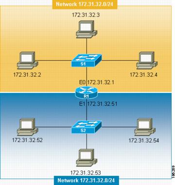
To help prevent mistakes as shown in the figure above, Cisco IOS-based networking devices will not allow you to configure
the same IP network address on two or more interfaces in the router when IP routing is enabled.
The only way to prevent the mistake shown in the figure below, where 172.16.31.0/24 is used in R2 and R3, is to have very
accurate network documentation that shows where you have assigned IP network addresses.
|
Ethernet 0 |
Serial 0 |
Serial 1 |
|---|---|---|
|
172.16.32.0/24 (Connected) |
192.168.100.4/29 (Connected) 172.16.31.0/24 RIP |
192.168.100.8/29 (Connected) 172.16.31.0/24 RIP |

For a more thorough explanation of IP routing, see the «Related Documents» section for a list of documents related to IP
routing.
Classless Inter-Domain Routing
Due to the continuing increase in internet use and the limitations on how IP addresses can be assigned using the class structure
shown in the table above, a more flexible method for allocating IP addresses was required. The new method is documented in
RFC 1519
Classless Inter-Domain Routing (CIDR): an Address Assignment and Aggregation Strategy. CIDR allows network administrators to apply arbitrary masks to IP addresses to create an IP addressing plan that meets the
requirements of the networks that they administrate.
For more information on CIDR, refer to RFC 1519 at
http://www.ietf.org/rfc/rfc1519.txt.
Prefixes
The term prefix is often used to refer to the number of bits of an IP network address that are of importance for building
routing tables. If you are using only classful (strict adherence to A, B, and C network address boundaries) IP addresses,
the prefixes are the same as the masks for the classes of addresses. For example, using classful IP addressing, a class C
IP network address such as 192.168.10.0 uses a 24-bit mask (/24 or 255.255.255.0) and can also be said to have a 24-bit prefix.
If you are using CIDR, the prefixes are arbitrarily assigned to IP network addresses based on how you want to populate the
routing tables in your network. For example, a group of class C IP addresses such as 192.168.10.0, 192.168.11.0, 192.168.12.0,
192.168.13.0 can be advertised as a single route to 192.168.0.0 with a 16-bit prefix (192.168.0.0/16). This results in a 4:1
reduction in the number of routes that the routers in your network need to manage.
How to Configure IP Addresses
Establishing IP Connectivity to a Network by Assigning an IP Address to an Interface
Perform this task to configure an IP address on an interface.
SUMMARY STEPS
-
enable
-
configure
terminal
-
interface
type
number
-
no
shutdown
-
ip
address
ip-address
mask
-
end
DETAILED STEPS
| Command or Action | Purpose | |
|---|---|---|
|
Step 1 |
Example: |
Enables privileged EXEC mode.
|
|
Step 2 |
Example: |
Enters global configuration mode. |
|
Step 3 |
Example: |
Specifies an interface and enters interface configuration mode. |
|
Step 4 |
Example: |
Enables the interface. |
|
Step 5 |
Example: |
Configures the IP address on the interface. |
|
Step 6 |
Example: |
Exits the current configuration mode and returns to privileged EXEC mode. |
Troubleshooting Tips
The following commands can help troubleshoot IP addressing:
-
show
ip
interface
—Displays the IP parameters for the interface. -
show
ip
route
connected
—Displays the IP networks the networking device is connected to.
Increasing the Number of IP Hosts that Are Supported on a Network by Using Secondary IP Addresses
If you have a situation in which you need to connect more IP hosts to
a network segment and you have used all of the available IP host addresses for
the subnet to which you have assigned the segment, you can avoid having to
readdress all of the hosts with a different subnet by adding a second IP
network address to the network segment.
Perform this task to configure a secondary IP address on an
interface.
SUMMARY STEPS
-
enable
-
configure
terminal
-
interface
type
number
-
no
shutdown
-
ip
address
ip-address
mask
-
ip
address
ip-address
mask
secondary
-
end
DETAILED STEPS
| Command or Action | Purpose | |
|---|---|---|
|
Step 1 |
Example: |
Enables privileged EXEC mode.
|
|
Step 2 |
Example: |
Enters global configuration mode. |
|
Step 3 |
Example: |
Specifies an interface and enters interface configuration mode. |
|
Step 4 |
Example: |
Enables the interface. |
|
Step 5 |
Example: |
Configures the IP address on the interface. |
|
Step 6 |
Example: |
Configures the secondary IP address on the interface. |
|
Step 7 |
Example: |
Exits the current configuration mode and returns to privileged |
Troubleshooting Tips
The following commands can help troubleshoot IP addressing:
-
show
ip
interface
—Displays the IP parameters for the interface. -
show
ip
route
connected
—Displays the IP networks the networking device is connected to.
What to Do Next
If your network has two or more routers and you have already configured a routing protocol, make certain that the other routers
can reach the new IP network that you assigned. You might need to modify the configuration for the routing protocol on the
router so that it advertises the new network. Consult the
Cisco IOS IP Routing: Protocol-Independent Configuration Guide for information on configuring routing protocols.
Maximizing the Number of Available IP Subnets by Allowing the Use of IP Subnet Zero
If you using subnetting in your network and you are running out of network addresses, you can configure your networking device
to allow the configuration of subnet zero. This adds one more usable network address for every subnet in your IP addressing
scheme. The table above shows the IP subnets (including subnet 0) for 172.16.0.0/20.
Perform this task to enable the use of IP subnet zero on your networking device.
SUMMARY STEPS
-
enable
-
configure
terminal
-
ip
subnet-zero
-
interface
type
number
-
no
shutdown
-
ip
address
ip-address
mask
-
end
DETAILED STEPS
| Command or Action | Purpose | |
|---|---|---|
|
Step 1 |
Example: |
Enables privileged EXEC mode.
|
|
Step 2 |
Example: |
Enters global configuration mode. |
|
Step 3 |
Example: |
Enables the use of IP subnet zero. |
|
Step 4 |
Example: |
Specifies an interface and enters interface configuration mode. |
|
Step 5 |
Example: |
Enables the interface. |
|
Step 6 |
Example: |
Configures the subnet zero IP address on the interface. |
|
Step 7 |
Example: |
Exits the current configuration mode and returns to privileged EXEC mode. |
Troubleshooting Tips
The following commands can help troubleshoot IP addressing:
-
show
ip
interface
—Displays the IP parameters for the interface. -
show
ip
route
connected
—Displays the IP networks the networking device is connected to.
Specifying the Format of Network Masks
By default,
show commands display an IP address and then its netmask in dotted decimal notation. For example, a subnet would be displayed
as 131.108.11.55 255.255.255.0.
You might find it more convenient to display the network mask in hexadecimal format or bit count format instead. The hexadecimal
format is commonly used on UNIX systems. The previous example would be displayed as 131.108.11.55 0XFFFFFF00.
The bit count format for displaying network masks is to append a slash (/) and the total number of bits in the netmask to
the address itself. The previous example would be displayed as 131.108.11.55/24.
Specifying the Format in Which Netmasks Appear for the Current Session
Perform this task to specify the format in which netmasks appear for the current session.
SUMMARY STEPS
-
enable
-
term
ip
netmask-format
{bitcount | decimal | hexadecimal }
DETAILED STEPS
| Command or Action | Purpose | |
|---|---|---|
|
Step 1 |
Example: |
Enables privileged EXEC mode.
|
|
Step 2 |
Example: |
Specifies the format the router uses to display network masks. |
Specifying the Format in Which Netmasks Appear for an Individual Line
Perform this task to specify the format in which netmasks appear for an individual line.
SUMMARY STEPS
-
enable
-
configure
terminal
-
line
vty
first
last
-
term
ip
netmask-format
{bitcount | decimal | hexadecimal } -
end
DETAILED STEPS
| Command or Action | Purpose | |
|---|---|---|
|
Step 1 |
Example: |
Enables privileged EXEC mode.
|
|
Step 2 |
Example: |
Enters global configuration mode. |
|
Step 3 |
Example: |
Enters line configuration mode for the range of lines specified by the first and last arguments. |
|
Step 4 |
Example: |
Specifies the format the router uses to display the network mask for an individual line. |
|
Step 5 |
Example: |
Exits the current configuration mode and returns to privileged EXEC mode. |
Using IP Unnumbered
Interfaces on Point-to-Point WAN Interfaces to Limit Number of IP Addresses
Required
If you have a limited
number of IP network or subnet addresses and you have point-to-point WANs in
your network, you can use the IP Unnumbered Interfaces feature to enable IP
connectivity on the point-to-point WAN interfaces without actually assigning an
IP address to them.
Perform this task to
configure the IP Unnumbered Interfaces feature on a point-to-point WAN
interface.
IP Unnumbered Feature
The IP Unnumbered Interfaces feature enables IP processing on a
point-to-point WAN interface without assigning it an explicit IP address. The
IP unnumbered point-to-point WAN interface uses the IP address of another
interface to enable IP connectivity, which conserves network addresses.
|
Note |
The following restrictions apply to the IP Unnumbered Interfaces
|
SUMMARY STEPS
-
enable
-
configure
terminal
-
interface
type
number
-
no
shutdown
-
ip
address
ip-address
mask
-
interface
type
number
-
no
shutdown
-
ip
unnumbered
type
number
-
end
DETAILED STEPS
| Command or Action | Purpose | |
|---|---|---|
|
Step 1 |
Example: |
Enables privileged EXEC mode.
|
|
Step 2 |
Example: |
Enters global configuration mode. |
|
Step 3 |
Example: |
Specifies an interface and enters interface configuration mode. |
|
Step 4 |
Example: |
Enables the interface. |
|
Step 5 |
Example: |
Configures the IP address on the interface. |
|
Step 6 |
Example: |
Specifies a point-to-point WAN interface and enters interface |
|
Step 7 |
Example: |
Enables the point-to-point WAN interface. |
|
Step 8 |
Example: |
Enables the IP unnumbered feature on the point-to-point WAN In this example the point-to-point WAN interface uses IP address |
|
Step 9 |
Example: |
Exits the current configuration mode and returns to privileged |
Troubleshooting Tips
The following commands can help troubleshoot IP addressing:
-
show
ip
interface
—Displays the IP parameters for the interface. -
show
ip
route
connected
—Displays the IP networks the networking device is connected to.
Using IP addresses with 31-Bit Prefixes on Point-to-Point WAN Interfaces to Limit Number of IP Addresses Required
You can reduce the number of IP subnets used by networking devices to establish IP connectivity to point-to-point WANs that
they are connected to by using IP Addresses with 31-bit Prefixes as defined in RFC 3021.
Perform this task to configure an IP address with a 31-bit prefix on a point-to-point WAN interface.
RFC 3021
Prior to RFC 3021,
Using 31-bit Prefixes on IPv4 Point-to-Point Links , many network administrators assigned IP address with a 30-bit subnet mask (255.255.255.252) to point-to-point interfaces
to conserve IP address space. Although this practice does conserve IP address space compared to assigning IP addresses with
shorter subnet masks such as 255.255.255.240, IP addresses with a 30-bit subnet mask still require four addresses per link:
two host addresses (one for each host interface on the link), one all-zeros network address, and one all-ones broadcast network
address.
The table below shows an example of the four IP addresses that are created when a 30-bit (otherwise known as 255.255.255.252
or /30) subnet mask is applied to the IP address 192.168.100.4. The bits that are used to specify the host IP addresses in
bold.
|
Address |
Description |
Binary |
|---|---|---|
|
192.168.100.4/30 |
All-zeros IP address |
11000000.10101000.01100100.00000100 |
|
192.168.100.5/30 |
First host addresses |
11000000.10101000.01100100.00000101 |
|
192.168.100.6/30 |
Second host address |
11000000.10101000.01100100.00000110 |
|
192.168.100.7/30 |
All-ones broadcast address |
11000000.10101000.01100100.00000111 |
Point-to-point links only have two endpoints (hosts) and do not require broadcast support because any packet that is transmitted
by one host is always received by the other host. Therefore the all-ones broadcast IP address is not required for a point-to-point
interface.
The simplest way to explain RFC 3021 is to say that the use of a 31-bit prefix (created by applying a 31-bit subnet mask
to an IP address) allows the all-zeros and all-ones IP addresses to be assigned as host addresses on point-to-point networks.
Prior to RFC 3021 the longest prefix in common use on point-to-point links was 30-bits, which meant that the all-zeros and
all-ones IP addresses were wasted.
The table below shows an example of the two IP addresses that are created when a 31-bit (otherwise known as 255.255.255.254
or /31) subnet mask is applied to the IP address 192.168.100.4. The bit that is used to specify the host IP addresses in bold
|
Address |
Description |
Binary |
|---|---|---|
|
192.168.100.4/31 |
First host address |
11000000.10101000.01100100.00000100 |
|
192.168.100.5/31 |
Second host address |
11000000.10101000.01100100.00000101 |
The complete text for RFC 3021 is available at
http://www.ietf.org/rfc/rfc3021.txt .
Before you begin
You must have classless IP addressing configured on your networking device before you configure an IP address with a 31-bit
prefix on a point-to-point interface. Classless IP addressing is enabled by default in many versions of Cisco IOS software.
If you are not certain that your networking device has IP classless addressing configured, enter the
ip
classless command in global configuration mode to enable it.
|
Note |
This task can only be performed on point-to-point (nonmultiaccess) WAN interfaces. |
SUMMARY STEPS
-
enable
-
configure
terminal
-
ip
classless
-
interface
type
number
-
no
shutdown
-
ip
address
ip-address
mask
-
end
DETAILED STEPS
| Command or Action | Purpose | |||
|---|---|---|---|---|
|
Step 1 |
Example: |
Enables privileged EXEC mode.
|
||
|
Step 2 |
Example: |
Enters global configuration mode. |
||
|
Step 3 |
Example: |
(Optional) Enables IP classless (CIDR).
|
||
|
Step 4 |
Example: |
Specifies a point-to-point WAN interface and enters interface configuration mode. |
||
|
Step 5 |
Example: |
Enables the interface. |
||
|
Step 6 |
Example: |
Configures the 31bit prefix IP address on the point-to-point WAN interface. |
||
|
Step 7 |
Example: |
Exits the current configuration mode and returns to privileged EXEC mode. |
Troubleshooting Tips
The following commands can help troubleshoot IP addressing:
-
show
ip
interface
—Displays the IP parameters for the interface. -
show
ip
route
connected
—Displays the IP networks the networking device is connected to.
Configuration Examples for IP Addresses
Example Establishing IP Connectivity to a Network by Assigning an IP Address to an Interface
The following example configures an IP address on three interfaces:
!
interface FastEthernet0/0
 no shutdown
 ip address 172.16.16.1 255.255.240.0
!
interface FastEthernet0/1
 no shutdown
 ip address 172.16.32.1 255.255.240.0
!
interface FastEthernet0/2
 no shutdown
 ip address 172.16.48.1 255.255.240.0
!
Example Increasing the Number of IP Hosts that are Supported on a Network by Using Secondary IP Addresses
The following example configures secondary IP addresses on three interfaces:
!
interface FastEthernet0/0
 no shutdown
 ip address 172.16.16.1 255.255.240.0
 ip address 172.16.32.1 255.255.240.0 secondary
!
!
interface FastEthernet0/1
 no shutdown
 ip address 172.17.16.1 255.255.240.0
 ip address 172.17.32.1 255.255.240.0 secondary
!
!
interface FastEthernet0/2
 no shutdown
 ip address 172.18.16.1 255.255.240.0
 ip address 172.18.32.1 255.255.240.0 secondary
!
Example Using IP Unnumbered
Interfaces on Point-to-Point WAN Interfaces to Limit Number of IP Addresses
Required
The following
example configures the unnumbered IP feature on three interfaces:
!
interface FastEthernet0/0
 no shutdown
 ip address 172.16.16.1 255.255.240.0
!
interface serial0/0
 no shutdown
 ip unnumbered fastethernet0/0
!
interface serial0/1
 no shutdown
 ip unnumbered fastethernet0/0
!
interface serial0/2
 no shutdown
 ip unnumbered fastethernet0/0
!
Example Using IP addresses
with 31-Bit Prefixes on Point-to-Point WAN Interfaces to Limit Number of IP
Addresses Required
The following
example configures 31-bit prefixes on two interfaces:
!
ip classless
!
interface serial0/0
 no shutdown
 ip address 192.168.100.2 255.255.255.254
!
!
interface serial0/1
 no shutdown
 ip address 192.168.100.4 255.255.255.254
Example Maximizing the Number of Available IP Subnets by Allowing the Use of IP Subnet Zero
The following example enables subnet zero:
!
interface FastEthernet0/0
 no shutdown
 ip address 172.16.16.1 255.255.240.0
!
ip subnet-zero
!
Where to Go Next
If your network has two or more routers and you have not already configured a routing protocol, consult the
Cisco IOS IP Routing Protocols Configuration Guide, Release 12.4T, for information on configuring routing protocols.
Additional References
Related Documents
|
Related Topic |
Document Title |
|---|---|
|
Cisco IOS commands |
Cisco IOS Master Commands List, All Releases |
|
IP addressing commands: complete command syntax, command mode, command history, defaults, usage guidelines, and examples |
Cisco IOS IP Addressing Services Command Reference |
|
Fundamental principles of IP addressing and IP routing |
IP Routing Primer ISBN 1578701082 |
Standards
|
Standard |
Title |
|---|---|
|
No new or modified standards are supported, and support for existing standards has not been modified |
— |
MIBs
|
MIB |
MIBs Link |
|---|---|
|
No new or modified MIBs are supported, and support for existing MIBs has not been modified |
To locate and download MIBs for selected platforms, Cisco software releases, and feature sets, use Cisco MIB Locator found http://www.cisco.com/go/mibs |
RFCs
|
RFC6 |
Title |
|---|---|
|
RFC 791 |
Internet Protocol http://www.ietf.org/rfc/rfc0791.txt |
|
RFC 1338 |
Classless Inter-Domain Routing (CIDR): an Address Assignment and Aggregation Strategy |
|
RFC 1466 |
Guidelines for Management of IP Address Space |
|
RFC 1716 |
Towards Requirements for IP Routers |
|
RFC 1918 |
Address Allocation for Private Internets |
|
RFC 3330 |
Special-Use IP Addresses |
the IETF RFC site at http://www.ietf.org/rfc.html for a full list of RFCs.
Technical Assistance
|
Description |
Link |
|---|---|
|
The Cisco Support and Documentation website provides online resources to download documentation, software, and tools. Use |
http://www.cisco.com/cisco/web/support/index.htmll |
Feature Information for IP Addresses
The following table provides release information about the feature or features described in this module. This table lists
only the software release that introduced support for a given feature in a given software release train. Unless noted otherwise,
subsequent releases of that software release train also support that feature.
Use Cisco Feature Navigator to find information about platform support and Cisco software image support. To access Cisco
Feature Navigator, go to www.cisco.com/go/cfn. An account on Cisco.com is not required.
|
Feature Name |
Releases |
Feature Information |
|---|---|---|
|
Classless Inter-Domain Routing |
10.0 |
CIDR is a new way of looking at IP addresses that eliminates the concept of classes (class A, class B, and so on). For example, The following command was introduced or modified: |
|
IP Subnet Zero |
10.0 |
In order to conserve IP address space IP Subnet Zero allows the use of the all-zeros subnet as an IP address on an interface, The following command was introduced or modified: |
|
IP Unnumbered Interfaces |
10.0 |
In order to conserve IP address space, IP unnumbered interfaces use the IP address of another interface to enable IP connectivity. The following command was introduced or modified: |
|
Using 31-bit Prefixes on IP Point-to-Point Links |
12.0(14)S 12.2(4)T |
In order to conserve IP address space on the Internet, a 31-bit prefix length allows the use of only two IP addresses on |
A subnet, or subnetwork, is a part of a larger network. Subnets are a logical part of an IP network into multiple, smaller network components. The Internet Protocol (IP) is the method for transmitting data from one computer to another over the internet network. Each computer, or host, on the internet, has at least one IP address as a unique identifier.
To learn about subnetting refer to Introduction to Subnetting.
Steps to Configure and Verify Three Router Connections in Cisco Packet Tracer:
Step 1: First, open the Cisco packet tracer desktop and select the devices given below:
| S.NO | Device | Model-Name | Qty. |
|---|---|---|---|
| 1. | PC | pc | 6 |
| 2. | Switch | PT-Switch | 3 |
| 3. | Router | PT-Router | 3 |
IP Addressing Table for PCs
| S.NO | Device | IPv4 Address | Subnet Mask | Default-Gateway |
|---|---|---|---|---|
| 1. | pc0 | 192.168.1.2 | 255.255.255.0 | 192.168.1.1 |
| 2. | pc1 | 192.168.1.3 | 255.255.255.0 | 192.168.1.1 |
| 3. | pc2 | 192.168.2.2 | 255.255.255.0 | 192.168.2.1 |
| 4. | pc3 | 192.168.2.3 | 255.255.255.0 | 192.168.2.1 |
| 5. | pc4 | 192.168.3.2 | 255.255.255.0 | 192.168.3.1 |
| 6. | pc5 | 192.168.3.3 | 255.255.255.0 | 192.168.3.1 |
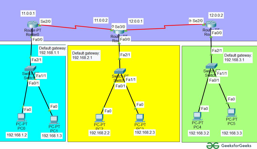
- Then, create a network topology as shown below the image.
- Use an Automatic connecting cable to connect the devices with others.
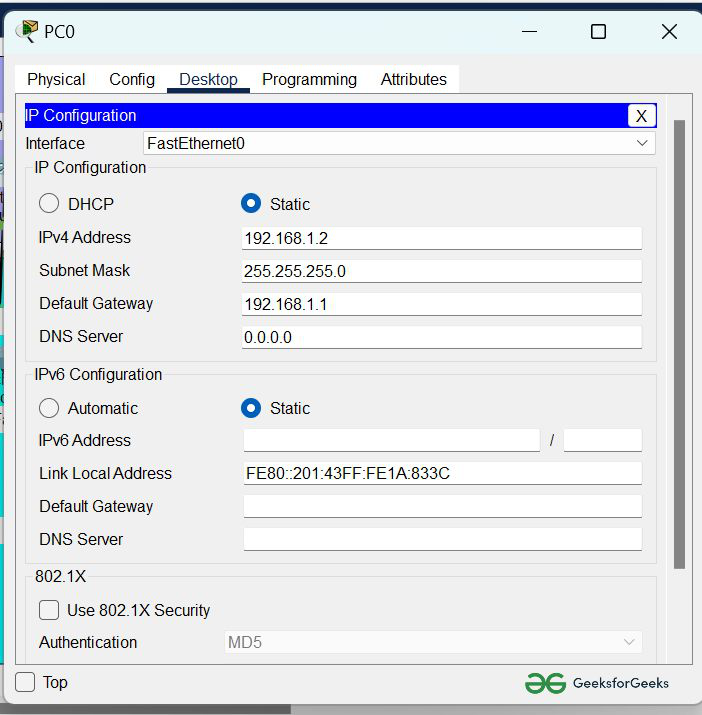
Step 2: Configure the PCs (hosts) with IPv4 address and Subnet Mask according to the IP addressing table given above.
- To assign an IP address in PC0, click on PC0.
- Then, go to desktop and then IP configuration and there you will IPv4 configuration.
- Fill IPv4 address and subnet mask.
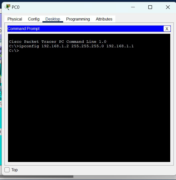
Assigning IP address using the ipconfig command.
- Or we can also assign an IP address with the help of a command.
- Go to the command terminal of the PC.
- Then, type ipconfig <IPv4 address><subnet mask><default gateway>(if needed)
Example: ipconfig 192.168.1.2 255.255.255.0 192.168.1.1
- Repeat the same procedure with other PCs to configure them thoroughly.
Step 3: Configure router with IP address and subnet mask.
IP Addressing Table Router
| S.NO | Device | Interface | IPv4 Address | Subnet mask |
|---|---|---|---|---|
| 1. | router0 | FastEthernet0/0 | 192.168.1.1 | 255.255.255.0 |
| Serial2/0 | 11.0.0.1 | 255.0.0.0 | ||
| 2. | router1 | Serial 2/0 | 11.0.0.2 | 255.0.0.0 |
| Serial 3/0 | 12.0.0.1 | 255.0.0.0 | ||
| 3. | router 3 | FastEthernet0/0 | 192.168.3.1 | 255.255.255.0 |
| Serial2/0 | 12.0.0.2 | 255.0.0.0 |
- To assign an IP address in router0, click on router0.
- Then, go to config and then Interfaces.
- Then, configure the IP address in FastEthernet and serial ports according to IP addressing Table.
- Fill IPv4 address and subnet mask.
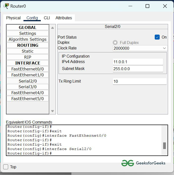
- Repeat the same procedure with other routers to configure them thoroughly.
Step 4: After configuring all of the devices we need to assign the routes to the routers.
To assign static routes to the particular router:
- First, click on router0 then Go to CLI.
- Then type the commands and IP information given below.
CLI command : ip route <network id> <subnet mask><next hop>
Static Routes for Router0 are given below:
Router(config)#ip route 192.168.2.0 255.255.255.0 11.0.0.2
Router(config)#ip route 11.0.0.0 255.0.0.0 11.0.0.2
Router(config)#ip route 192.168.3.0 255.255.255.0 11.0.0.2
Router(config)#ip route 12.0.0.0 255.0.0.0 11.0.0.2
Static Routes for Router1 are given below:
Router(config)#ip route 192.168.1.0 255.255.255.0 11.0.0.1
Router(config)#ip route 11.0.0.0 255.0.0.0 11.0.0.1
Router(config)#ip route 192.168.3.0 255.255.255.0 12.0.0.2
Router(config)#ip route 12.0.0.0 255.0.0.0 12.0.0.2
Static Routes for Router2 are given below:
Router(config)#ip route 192.168.1.0 255.255.255.0 12.0.0.1
Router(config)#ip route 11.0.0.0 255.0.0.0 12.0.0.1
Router(config)#ip route 12.0.0.0 255.0.0.0 12.0.0.1
Router(config)#ip route 192.168.2.0 255.255.255.0 12.0.0.1
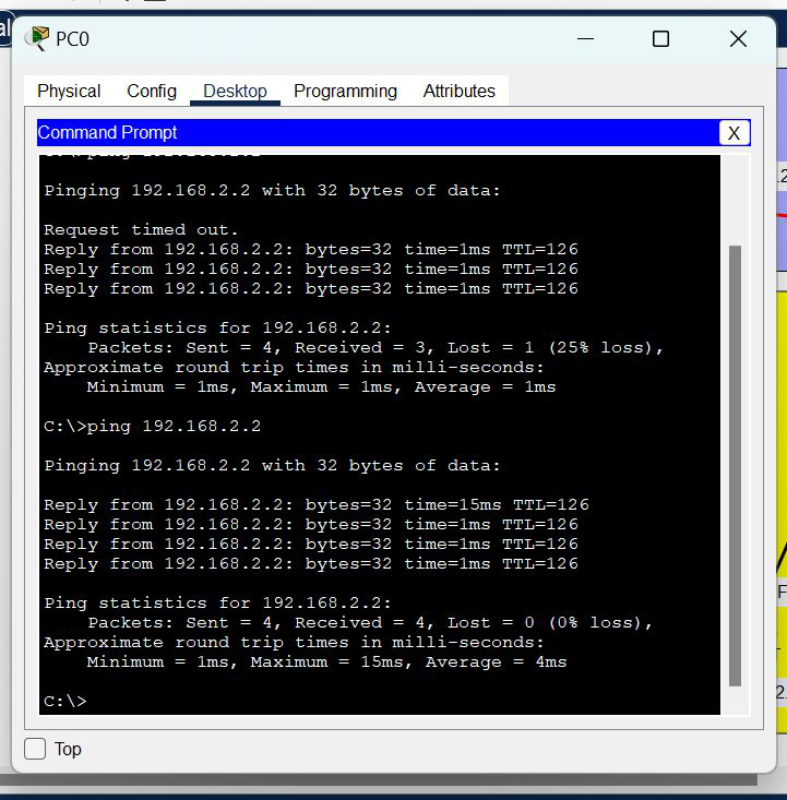
Step 5: Verifying the network by pinging the IP address of any PC. We will use the ping command to do so.
- First, click on PC0 then Go to the command prompt
- Then type ping <IP address of targeted node>
- As we can see in the below image we are getting replies which means the connection is working very fine
Example : ping 192.168.2.2
- A simulation of the experiment is given below we are sending PDU from PC0 to PC3 and PC2 to PC4:
Last Updated :
26 Jun, 2022
Like Article
Save Article
Настройка подсети на оборудовании Cisco — важный этап в создании сети, который обеспечивает эффективное распределение IP-адресов и гарантирует надежную работу компьютерной сети. В данной статье мы рассмотрим подробный процесс настройки подсети на сетевых устройствах Cisco.
Сначала необходимо определиться с IP-адресами, использование которых будет предусмотрено в подсети. Основная задача — выбрать IP-адреса, которые будут уникальными в пределах сети. Для этого можно воспользоваться специальными инструментами, такими как калькулятор IP-адресов, который позволяет определить диапазон доступных IP-адресов.
После выбора IP-адресов необходимо приступить к настройке подсети на оборудовании Cisco. Для этого используется командный интерфейс Cisco IOS. Перед началом настройки подсети необходимо убедиться, что сетевое оборудование корректно подключено и готово к работе.
Далее следует выполнить следующие шаги: установить IP-адрес на интерфейсе маршрутизатора или коммутатора, настроить маршрутизацию между подсетями и провести проверку работоспособности настроенной подсети. При необходимости можно настроить дополнительные параметры, такие как маска подсети, шлюз по умолчанию, DNS-серверы и другие.
Настройка подсети на оборудовании Cisco — неотъемлемая часть работы сетевых специалистов и компьютерных инженеров. Правильная настройка подсети обеспечивает безопасность, гибкость и эффективность работы компьютерной сети. Используя это подробное руководство, вы сможете без труда настроить подсеть на оборудовании Cisco и обеспечить оптимальную работу вашей сети.
Содержание
- Подготовка к настройке
- Определение IP-адреса для подсети
- Настройка маршрутизатора
- Настройка свитча
- Проверка подсети и устранение ошибок
Подготовка к настройке
Перед тем, как приступить к настройке подсети на оборудовании Cisco, необходимо выполнить ряд подготовительных шагов. Эти шаги помогут вам сделать процесс настройки более гладким и эффективным.
1. Изучите документацию
Перед началом настройки, рекомендуется ознакомиться с документацией, предоставленной Cisco для вашего конкретного устройства. Это поможет вам лучше понять особенности вашего оборудования и правильно выполнять настройки.
2. Сделайте копию текущей конфигурации
Перед внесением изменений в настройки, рекомендуется сделать резервную копию текущей конфигурации устройства. Это позволит вам восстановить предыдущую конфигурацию в случае нежелательных результатов или ошибок в процессе настройки.
3. Создайте план настройки
Прежде чем приступать к настройке, рекомендуется создать план, который включает в себя все требуемые изменения и конфигурационные настройки. Это поможет вам структурировать процесс настройки и предотвратить возможные ошибки или упущения.
4. Подготовьте необходимые материалы
Убедитесь, что у вас есть все необходимые материалы для настройки подсети на Cisco, такие как консольный кабель, патч-корды, коннекторы и т.д. Также убедитесь, что вы имеете доступ к необходимой документации и программному обеспечению, которое может потребоваться в процессе настройки.
5. Проведите тестирование
Прежде чем внести изменения в рабочую сеть, рекомендуется провести тестирование настройки в тестовой среде или на отдельном устройстве. Это поможет вам убедиться в правильности настройки и исключить возможные непредвиденные проблемы.
Правильная подготовка перед настройкой подсети на Cisco поможет вам сделать процесс настройки более плавным и успешным. Придерживайтесь этих рекомендаций и вы сможете эффективно настроить подсеть на Cisco.
Определение IP-адреса для подсети
При определении IP-адреса для подсети необходимо учитывать следующие факторы:
- Выберите IP-адрес, который находится в диапазоне нераспределенных IP-адресов вашей сети.
- Выберите уникальный IP-адрес для данной подсети, чтобы избежать конфликтов с другими устройствами в сети.
- Выберите IP-адрес, который будет легко запомнить и идентифицировать сеть.
Рекомендуется использовать стандартные IP-адреса, которые не принадлежат никакой конкретной организации или устройству. Некоторые часто используемые стандартные IP-адреса для сетей включают: 192.168.0.0, 10.0.0.0, 172.16.0.0.
После определения и настройки IP-адреса для подсети на устройствах Cisco, устройства будут способны обмениваться информацией и проходить трафик друг к другу в пределах данной подсети.
Настройка маршрутизатора
Для начала настройки маршрутизатора необходимо подключиться к нему через программу терминала или консоли. Затем следует выполнить следующие действия:
1. Вход в режим настройки маршрутизатора:
$ enable
2. Вход в режим глобальной конфигурации:
# configure terminal
3. Назначение IP-адреса интерфейсу:
(config)# interface <interface_name>
(config-if)# ip address <ip_address> <subnet_mask>
4. Активация интерфейса:
(config-if)# no shutdown
5. Настройка маршрутизации:
(config)# ip route <destination_network> <subnet_mask> <next_hop_ip>
6. Сохранение настроек:
(config)# end
# copy running-config startup-config
После выполнения всех этих действий маршрутизатор будет настроен и готов к использованию в вашей подсети.
Важно помнить, что маршрутизаторы являются индивидуальными устройствами, поэтому настройки могут отличаться в зависимости от модели и версии программного обеспечения.
Настройка свитча
Для начала настройки свитча необходимо подключиться к управляющему интерфейсу свитча с помощью консольного кабеля и программы для конфигурирования, такой как PuTTY или HyperTerminal.
После установки соединения откройте программу и выберите порт, к которому подключен свитч. Затем нажмите кнопку «Подключиться» и укажите настройки подключения (скорость передачи данных, биты данных, проверка на четность, стоп-биты и поток управления). Настройки могут различаться в зависимости от типа консольного кабеля и соединения.
После успешного подключения вы увидите командную строку свитча. Введите имя пользователя и пароль для входа в систему свитча (обычно по умолчанию — «cisco» и «cisco»). Если требуется, введите команду «enable» для получения расширенных привилегий.
После входа в систему вы можете начать настройку свитча с помощью различных команд. Некоторые основные команды, которые могут быть полезны:
| Команда | Описание |
|---|---|
| enable | Переход в режим привилегий EXEC |
| configure terminal | Переход в режим настройки |
| interface GigabitEthernet0/1 | Выбор интерфейса для настройки |
| ip address 192.168.1.1 255.255.255.0 | Назначение IP-адреса и маски подсети |
| exit | Возврат к предыдущему режиму |
| copy running-config startup-config | Сохранение настроек в постоянной памяти |
Это только основные команды, их список и функциональность могут быть разными в зависимости от модели свитча и версии ПО. При настройке свитча рекомендуется обращаться к документации Cisco или обратиться к специалисту для получения дополнительной информации.
После внесения всех необходимых настроек не забудьте сохранить их, используя команду «copy running-config startup-config». Это позволит сохранить настройки свитча в постоянной памяти и автоматически загрузить их при каждом включении свитча.
Теперь вы готовы использовать свитч и настроенную подсеть для обеспечения коммуникации между компьютерами и устройствами в рамках вашей сети.
Проверка подсети и устранение ошибок
После настройки подсети на оборудовании Cisco очень важно проверить ее работоспособность и обнаружить возможные ошибки. Следующие шаги помогут вам проверить настройки и исправить неполадки в подсети:
1. Проверьте настройки IP-адресов:
Убедитесь, что все устройства в подсети имеют правильно настроенные IP-адреса. Проверьте, что IP-адрес каждого устройства находится в той же подсети и имеет правильно указанную маску подсети.
2. Проверьте наличие связности:
Убедитесь, что все устройства в подсети могут обмениваться пакетами данных. Для этого можно использовать команду ping на каждом устройстве, чтобы проверить доступность других устройств в сети.
3. Проверьте настройки маршрутизации:
Убедитесь, что маршрутизаторы в подсети имеют правильную таблицу маршрутизации и настроены на пересылку пакетов между подсетями. Используйте команду show ip route на маршрутизаторе, чтобы проверить таблицу маршрутизации.
4. Проверьте настройки безопасности:
Убедитесь, что настройки безопасности подсети соответствуют вашим требованиям. Проверьте правила фильтрации трафика на маршрутизаторах и коммутаторах, чтобы удостовериться, что только разрешенный трафик проходит через подсеть.
5. Проверьте работоспособность сервисов:
Проверьте, что все сервисы, которые должны быть доступны в подсети, работают должным образом. Например, убедитесь, что DHCP-сервер выдает IP-адреса, DNS-сервер отвечает на запросы DNS и т. д.
При обнаружении ошибок и неполадок в подсети, тщательно проведите анализ причины и примите необходимые меры для устранения неполадок. Это может включать настройку корректных IP-адресов, проверку соединений, перезагрузку устройств, обновление прошивок и другие действия, чтобы гарантировать стабильную работу подсети.