Юникастовая маршрутизация мультикаст-трафика
Время на прочтение
4 мин
Количество просмотров 14K
Предисловие
Недавно мною было замечено, что при просмотре мультикастового IPTV через Wi-Fi часть трафика теряется. После детального изучения проблемы было выяснено, что такое поведение объясняется природой мультикаст-трафика, а именно – MAC-адрес получателя пакета. Он не зависит от получателя и формируется из адреса мультикаст-группы. Соответственно, на такие пакеты претендуют все клиенты, подключенные к беспроводной точке доступа. Вследствие этого нам достается лишь часть пакетов и мы видим обрывистую картинку.
Штатными средствами проблема решается либо созданием отдельной точки доступа для клиента, либо созданием статического маршрута для определенных мультикаст-групп, или же выведением клиента в отдельный VLAN. Вся “сила” таких решений проявится, когда в сети будет несколько IPTV-приставок, желающих посмотреть один и тот же канал, плюс необходимость их в интернете добавит сложность к настройке роутера. Свое решение данной проблемы предлагаю ниже.
Программы типа udpxy здесь не подходят, так как они меняют полную структуру пакета. А нам необходимо лишь установить необходимый MAC-адрес, при этом сохраняя сетевую и транспортную части, чтобы клиентское ПО не заметило никаких изменений.
Данное решение, назовем его MUT (Multicast to Unicast Translation), заключается в следующем:
- Узнать IP-адрес клиента, желающего подключиться к группе
- Сообщить об этом ядру ОС
- Узнать по IP-адресу MAC-адрес клиента
- Создать и отправить копию пакета на соответствующий интерфейс
Выполнение шагов 1 и 2 лежит на программе мультикастовой маршрутизации, 3 и 4 – на ядре. И то и другое требует небольших изменений в своей работе. Вся работа будет проходить в ОС GNU/Linux.
Немного теории
Сетевая маршрутизация IP версии 4 в Linux базируется на следующий структурах:
- sk_buff – самая часто используемая структура и представляет из себя весь сетевой пакет. Она передается из функции в функцию по пути меняя свое содержимое.
- rtable + dst_entry – две структуры, хранящие результат кэширования маршрута, полученный из таблицы маршрутизации. В зависимости от адреса получателя, адреса источника и поля TOS пакета определяется дальнейшая политика по отношению к нему. Эти две структуры хранят важную информацию для нас: интерфейс, через который будет проходить отправка, и поле шлюз — будущий L2-сосед, которому можно отправить пакет, не меняя L3-заголовок. Поиск кэша для каждого кадра производится два раза: один раз на входе (входящий трафик) и второй раз на выходе (исходящий). Нас интересует второй.
- neighbour – каждый экземпляр этой структуры представляет собой L2-соседа для определенного IP-адреса получателя. Он содержит MAC-адрес получателя, полученный после ARP-ответа; очередь из sk_buff, которые необходимо отправить после определения MAC-адреса; таймеры и многое другое. Для мультикаст-групп соседи тоже создаются, только MAC-адрес генерируется функцией. Нам же следует избежать этого.
В Linux маршрутизация мультикаст-трафика полностью контролируется из области пользователя, а именно программой-маршрутизатором. Ключевым элементом в мультикаст-маршрутизации является структура mfc_cache. Это связанный список, который хранит всю информацию о каждом маршруте: адрес источника потока, статистику, дальнейший маршрут и т.д. Добавление и удаление mfc_cache-структур осуществляется пользовательской программой.
Схематическое представление mfc_cache-списка:

Изображение взято из книги “Linux Networking Architecture”
Разработка
За основу было взято ядро Linux 3.18. Для хранения IP-адресов клиентов для каждой мультикаст-группы расширяем mfc_cache связанным списком:
struct mut_dst {
    struct list_head list;
    __be32 ip;
    struct rcu_head rcu;
};
Вводим новую функцию
ipmr_unicast_xmit
. В ней будет генерироваться юникастовый rtable, но передавать при этом будем мультикастовый sk_buff. Таким образом мы выбираем необходимый интерфейс для будущей отправки.
Теперь для того, чтобы в дальнейшем был создан neighbour для нашего получателя, а не для мультикаст-группы, в rtable указываем шлюз. За это отвечает поле
rt_gateway
:
struct rtable *rt;

rt = ip_route_output_ports(net, &fl4, NULL, m_dst->ip, 0, 0, 0, IPPROTO_IPIP, RT_TOS(iph->tos), 0);

if (IS_ERR(rt))
    goto out_free;

rt->rt_gateway = m_dst->ip;
dev = rt->dst.dev;
Вводим sysctl-переменную /proc/sys/net/ipv4/mut. Она даст возможность смены режима работы ядра “на лету”.
Справка
sysctl net.ipv4.mut=1 – Включает новый режим
sysctl net.ipv4.mut=0 – Возвращает режим стандартной маршрутизации
Как и раньше можно посмотреть список маршрутов, теперь еще и unicast:
root@multicast:~# cat /proc/net/ip_mr_cache

Group     Origin Iif Pkts  Bytes    Wrong Dsts

0520C3EF           2 18842 25323648     0 01000A0A
Подробнее со всеми изменениями можно ознакомиться в репозитории. Ссылка в конце статьи.
Наглядное представление работы (изменения в колонке с MAC-адресом):
Маршрутизатор
За основу взята программа IGMPProxy. Можно было взять любую другую, тот же mrouted. Очень важно, что все IGMP-сообщения отправляются от IP-адреса запрашивающего интерфейса, и нам ни что не мешает его использовать. Подробности изменений описывать смысла нет, их также можно найти в соответствующем репозитории. Главное то, что в управлении ядра появляются две новые команды, которые должна поддерживать программа:
- MRT_MUT_ADD_DST (212) — добавление получателя
- MRT_MUT_DEL_DST (213) — удаление получателя
Вместе с ними передается структура вида:
struct <name> {
	struct in_addr group; 		// Адрес группы
	struct in_addr origin;		// Адрес источника
	struct in_addr destination;	// Адрес клиента
}
Предупреждение
Стоит заметить, что такой подход не дает возможности отключать клиентов от групп за отсутствие от них Membership Report-запросов, так как, исходя из протокола IGMP, клиент, получивший от другого клиента такой запрос с той же группой, сам не отправляет аналогичный. Поэтому отключение возможно только после получения явного Leave Group-пакета.
Использование
Для включения новой возможности необходимо скомпилировать ядро с опцией CONFIG_IP_MUT=y
Для полноценной работы измененной IGMPProxy также необходимо включить CONFIG_SYSCTL_SYSCALL=y
Ссылки
Измененное ядро
Измененный IGMPProxy
Использованная литература
Rami Rosen «Linux Kernel Networking. Implementation and Theory»
Christian Benvenuti «Understanding Linux Network Internals»
Klaus Wehrle and Frank Pahlke «Linux Networking Architecture»
Если у кого-нибудь есть иной способ решения проблемы, прошу поделиться в комментариях.
Multicast has brought a lot of efficiencies to IP networks. But multicast wasn’t designed for wireless, and especially isn’t well suited for high-bandwidth multicast applications like video. I’ll cover the challenges of multicast over wireless and design considerations.
But first, an overview of multicast:
To level set, I’ll briefly cover IP multicast. For the purposes of this article, I’ll focus specifically on Layer 2, If you’re already familiar with multicast over ethernet, feel free to skip this section.
What is multicast?
In short, multicast is a means of sending the same data to multiple recipients at the same time without the source having to generate copies for each recipient. Whereas broadcast traffic is sent to every device whether they want it or not, multicast allows recipients to subscribe to the traffic they want. As a result, efficiency is improved (traffic is only sent once) and overhead is reduced (unintended recipients don’t receive the traffic).
How does it work?
With multicast, the sender doesn’t know who the recipients are, or even how many there are. In order for a given set of traffic to reach its intended recipients, we send traffic to multicast groups. IANA has reserved 224.0.0.0 – 239.255.255.255 for multicast groups, with 239.0.0.0/8 commonly used within private organizations. Traffic is sent with the unicast source IP of the sender, and a destination IP of the chosen multicast group.
On the receiving side, recipients subscribe to a multicast group using Internet Group Management Protocol (IGMP). A station that wishes to join a multicast group sends an IGMP Membership Report / Join message for that given group. Most enterprise switches, WLCs, or APs use IGMP snooping to inspect IGMP packets and populate their multicast table, which matches ports/devices to multicast groups. Then, when a multicast packet is received, the network device can forward that packet to the intended receivers. Network devices that don’t support IGMP snooping will forward the packet the same as it would a broadcast, to every port except the port the packet came in on. Here’s an example of an IGMP Join request:

The problems with multicast over WiFi vs wired
In a switched wired network, all traffic is sent at the same data rate (generally 1Gbps today) and with each port being its own collision domain, collisions are rare. In addition, wired traffic uses a bounded medium, so interference and frame corruption is also rare. Because of this, there is no network impact to sending large amounts of wired traffic as multicast. WiFi does not share either of these characteristics, which makes multicast more complicated. Below are some of the issues with multicast to multicast over WiFi:
- Multicast traffic is sent at a mandatory data rate. As mentioned, WiFi clients share a collision domain. Because multicast is a single transmission that must be received by all transmitted receivers, access points are forced to send that frame at the lowest-common-denominator settings, to give the receivers the best chance of hearing the transmission uncorrupted. While this is fine for small broadcast traffic like beacons, it’s unsustainable for high-bandwidth applications.
- Low data-rate traffic consumes more air time. Because multicast traffic is sent at a low data rate, it takes longer for each of those transmissions to complete. A 1MB file sent at a data rate of 1 Mbps will take significantly longer than the same file at a data rate of 54Mbps. This means that all other stations must spend more time waiting for their turn to transmit.
- Battery-powered clients have reduced battery life. Multicast and broadcast traffic are sent at the DTIM interval, which all stations keep track of. When a multicast frame is sent, all stations must wake up to listen to the frame, and discard it if they don’t need it. This results in battery-powered devices staying awake for a lot longer than needed. If the DTIM interval is too high, the increased latency can impact real-time applications like video. But the lower the DTIM interval, the more often stations need to wake up.
- Multicast senders will not resend corrupt frames. Frame corruption and retransmissions are a standard part of any WiFi transaction. Every unicast frame, even if unacknowledged at upper OSI layers such as when using UDP, are acknowledged at Layer 2, and retransmitted by the sending station if necessary. This may not seem like a big deal at first, as unacknowledged traffic on a wired network works fine most of the time. But in an area of interference or poor RSSI level, it’s not unusual to see 10% of wireless frames retransmitted. 10% loss would be considered extremely high on a wired network, and most applications are unable to handle this level of loss.
So how do we fix it?
There’s no silver bullet to “fixing” multicast over wireless, but there are a few ways to design around the shortcomings.
- Increasing the minimum data rate. An increase to the minimum data rate means that broadcast and multicast frames must be sent at the higher rate. Unicast traffic is acknowledged at Layer 2, reducing loss experienced by the upper layers. As mentioned earlier, higher data rates reduce the time spent transmitting, and increase throughput for the multicast traffic. It also reduces the amount of time a battery powered device must spend listening to the frames. However, other design and configuration considerations must be made to ensure the wireless network can support this, as changing the minimum data rate can impact roaming, as well as connectivity for low-powered devices.
- Multicast-to-Unicast Conversion (M-to-U). Many vendors of wireless APs support multicast-to-unicast conversion, which sends a unicast copy the frame to each intended receiver, using IGMP snooping to determine those stations. This means that the frame can be sent at the receiving station’s best data rate, which should almost always be above the minimum. Several unicast transmissions at 54Mbps would still use less channel time than the same multicast transmission at 1Mbps. In addition, stations which aren’t the intended receivers don’t need to wake up to listen to the frame, reducing their battery consumption.
The pudding
Let’s take a look at the same multicast frame sent with and without Multicast-to-Unicast Conversion. Using iperf2 (since iperf3 doesn’t support multicast), we’ll generate multicast traffic at a rate of 20Mbps from a wired client and send it to a wireless client, using multicast address 239.255.1.2.
Parameters for this test:
Receiver: MacBook Pro (2015 edition). 3 spatial stream 802.11ac airport card.
Access Point: Cisco Meraki MR42E (802.11ac Wave 2, 3×3:3) with omni-directional dipole antennas.
Wired Multicast Source (10.1.1.216):

Wireless Multicast Recipient (M-to-U enabled):

Wireless Multicast Recipient (M-to-U disabled):

The first thing to notice is the loss rate. With M-to-U enabled, my 20Mbps stream was successfully being transmitted with almost no loss. With M-to-U disabled, throughput was reduce by roughly 95%, with an average of 1Mbps throughput. There are two reasons for this: first, the mandatory data rate used for the multicast transmission was 6Mbps, of which ~40% is attributed to protocol overhead. In addition, with a unicast transmission the AP can buffer frames to a receiver, whereas a multicast transmission is best effort: it has no layer 2 acknowledgement or communication from the receivers. This can be improved with application-level handling, such as the application deciding to transmit at a lower quality, but there are no guarantees that the application is set up to handle that. iperf has no such throttling/accommodation.
To dive in further, let’s take a look at the differences in the frames transmitted:
Frame Capture (M-to-U enabled):

Frame Capture (M-to-U disabled):

We can verify that the second frame is using multicast by the MAC address in the Destination Address field, since all multicast MACs begin with 01-00-5E. Notice also that the source address of the unicast frame is set to the MAC address of the access point as the AP had to generate that frame, whereas the multicast frame’s source is that of the sending station since there was no frame modification needed.
Next, we’ll look at the data rate. Multicast is always sent at the basic rate, which was 6 Mbps for this BSSID, and a transmission time of 2072μs. Compared to M-to-U with a data rate of 540Mbps and a transmission time of 46μs. That means that the multicast transmission held the channel 45 times longer than the unicast, and still only sent half as much data.
Also, since multicast must use the lowest-common-denominator parameters, it cannot take advantage of efficiency improvements such as A-MPDU and multiple spatial streams offered by this AP.
So wouldn’t M-to-U be the silver bullet solution?
As is often the case, the answer is “it depends”. In a lab where my 3 spatial stream MacBook Pro can connect at MCS 8, it may appear so. But, if the majority of clients are connected at a low data rate, and the content only consumes a small amount of bandwidth, the overhead caused by retransmitting small frames for a large number of receivers could add delay and consume more aggregate airtime than simply transmitting once at a low data rate.
kmgmt3146-multicast-to-unicast-feature-cbw
Objective
The objective of this document is to show you how to configure multicast to unicast feature on your Cisco Business Wireless (CBW) Access Point (AP).
Applicable Devices | Software Version
- Cisco Business Wireless 140AC Access Point | 10.6.1.0 (Download latest)
- Cisco Business Wireless 145AC Access Point | 10.6.1.0 (Download latest)
- Cisco Business Wireless 240AC Access Point | 10.6.1.0 (Download latest)
Introduction
If you have CBW gear in your network, you can now use the new multicast to unicast feature in firmware version 10.6.1.0! Click if you would like step-by-step instructions on doing a firmware update.
Multicast allows a host to send packets to a subset of all hosts as a group transmission. The multicast to unicast feature enables better usage of the wireless bandwidth by converting the multicast frame to a unicast frame over the air. This results in a more reliable multicast stream to wireless clients. Each media stream client acknowledges receiving a video IP multicast stream. This feature is also known as multicast direct.
Things to remember:
- Multicast uses IPv4 addresses in the range of 224.0.0.0 through 239.255.255.255.
- A multicast MAC address will always begin with 01:00:5e.
- The range from 0100.5e00.0000 through 0100.5e7f.ffff is the available range of Ethernet MAC addresses for IP multicast.
Configure Multicast to Unicast
Step 1
Login to the web user interface (UI) of the CBW AP.
Step 2
Switch to expert view by clicking the bi-directional arrow icon.

Step 3
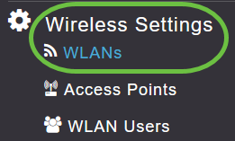
Navigate to Wireless Settings > WLANs.
Step 4
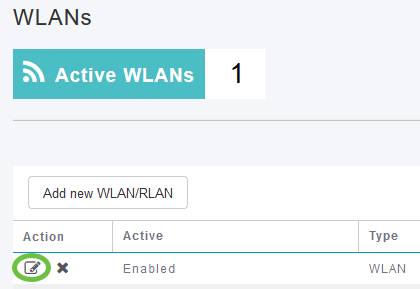
Choose the WLAN on which you want to enable multicast to unicast feature and click edit.
Step 5
Select the Traffic Shaping tab.

Step 6
From the QoS drop-down menu, select Platinum or Gold.

If QoS is set to Silver or Bronze, you will not be able to turn on the multicast direct toggle button in Step 8.
Step 7
Navigate to Advanced tab.

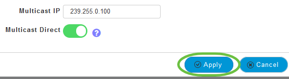
Step 8
Enter the Multicast IP address and click the toggle to enable Multicast Direct.
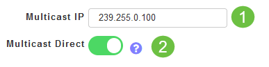
When Multicast Direct toggle button is enabled, the multicast packets will be converted to unicast packets by the AP and will be sent to the clients. If it is disabled, the multicast packets will be directly sent to the wireless clients.
Step 9
Click Apply to save the settings.
Step 10
Once the WLAN is configured, navigate to Services > Media Stream.
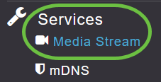
Services will only be visible under Expert View.
Step 11
Enable Global Multicast to support multicast traffic on Primary AP and Multicast Direct to enhance the video streaming for wireless clients. By default, both are disabled.
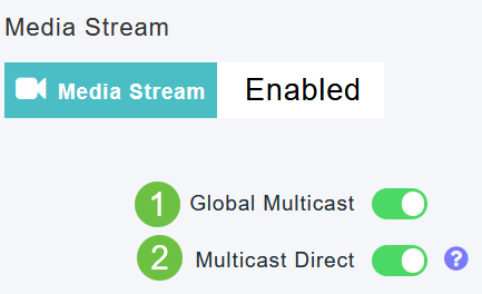
Global Multicast cannot be enabled without configuring IPv4 multicast address in WLAN section. Enabling the Multicast Direct feature does not automatically reset the existing client state. The wireless clients must re-join the multicast stream after enabling the multicast direct feature on the Primary AP.
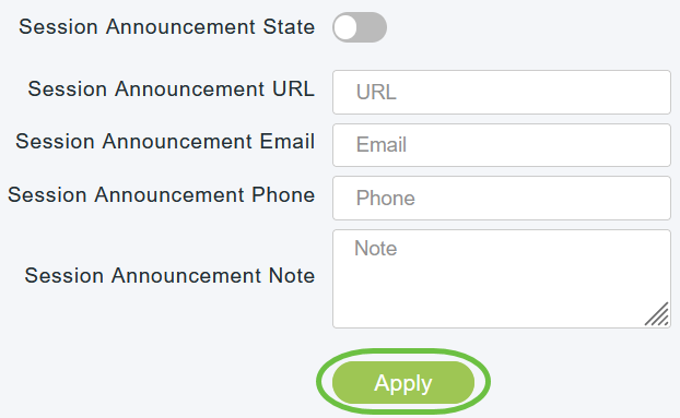
Step 12
(Optional)
You can enable the Session Announcement State. If this is enabled, clients are informed each time a Primary AP is not able to serve the multicast direct data to the client. Configure the Session Announcement parameters by entering the following:
- Session Announcement URL — Enter the URL where the client can find more information when an error occurs during the multicast media stream transmission.
- Session Announcement Email — Enter the email address of the person who can be contacted.
- Session Announcement Phone — Enter the phone number of the person who can be contacted.
- Session Announcement Note — Enter a note on why a particular client cannot be served with the multicast media.
Click Apply.
Step 13
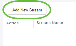
To add a media stream, click Add New Stream.
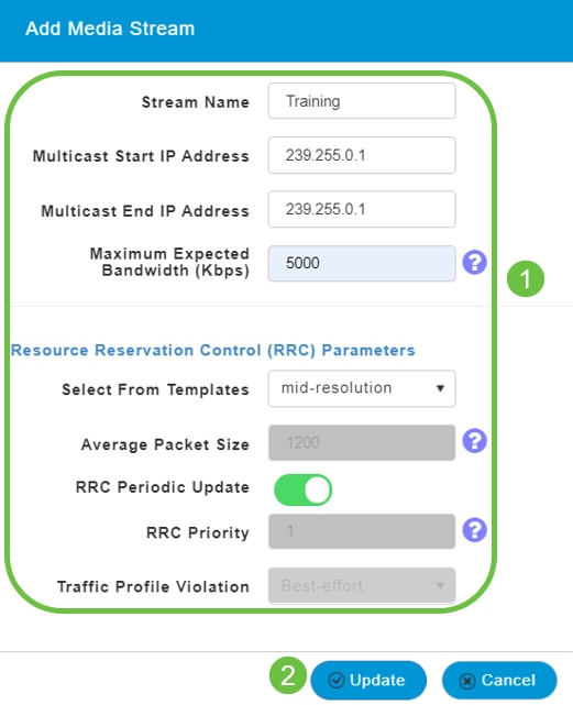
Step 14
Configure the following parameters:
- Stream Name — Enter a name for the stream, which can be up to 64 characters.
- Multicast Start IP Address — Enter the start IPv4 address of the multicast media stream.
- Multicast End IP Address — Enter the end IPv4 address of the multicast media stream.
- Maximum Expected Bandwidth (Kbps) — Enter the maximum expected bandwidth that you want to assign to the media stream. The default is 500 with a range of 1 to 35000 kbps.
- Select from Templates — Choose one of the options from the drop-down list to specify the details about the resource reservation control:
- Very Coarse (below 300 kbps)
- Coarse (below 500 kbps)
- Ordinary (below 750 kbps)
- Low (below 1 Mbps)
- Medium (below 3 Mbps)
- High (below 5 Mbps)
- Average Packet Size — Default value is 1200 but can range from 100 to 1500 bytes.
- RRC Periodic Update — Default option is enabled. RRC periodically updates the admission decision on the admitted stream according to the correct channel load. As a result, it may deny certain low priority admitted stream requests.
- RRC Priority — Used to specify the priority bit set in the media stream. The priority can be any number between 1 and 8. The larger the value, higher the priority. For example, a priority of 1 is the lowest value and a value of 8 is the highest value. The default priority is 4. The low priority stream may be denied in the RRC periodic update.
- Traffic Profile Violation — Used to specify the action to perform in case of a violation after a re-RRC. Select one of the two options from the drop-down menu:
- Best Effort — This is the default value. Specifies that a stream is set to Best Effort class on periodic revaluation.
- Drop — Specifies that a stream is dropped on periodic revaluation
Click the Update button.
Viewing Media Stream Clients
To see which client systems are connecting to the stream and if multicast direct is enabled, navigate to Services > Media Stream. Scroll down to Media Stream Clients section.
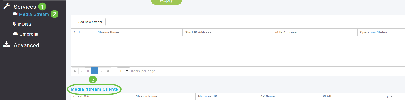
In this example, three wireless clients are connected to the multicast stream and all three are using multicast direct.

Conclusion
There you go! You have now successfully configured multicast to unicast feature on your CBW AP.
Revision History
| Revision | Publish Date | Comments |
|---|---|---|
|
1.0 |
02-Sep-2021 |
Initial Release |
Настройка IPTV
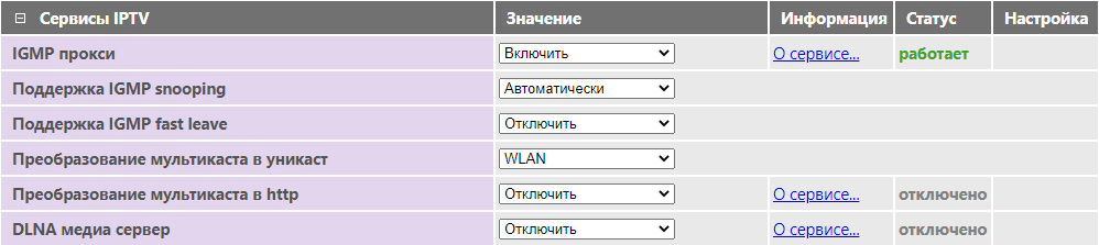
Маршрутизаторы SNR поддерживают трансляцию интернет-телевидения (IPTV) по технологии multicast. По умолчанию поддержка IPTV включена. Для включения IPTV перейдите на вкладку Сервисы – Разное в раздел Сервисы IPTV и выберите значение Включить для пункта IGMP прокси (IGMP Proxy), затем нажмите Применить.
Следующие настройки рекомендуем оставить по умолчанию:
- Поддержка IGMP snooping – в значении Автоматически,
- Преобразование мультикаста в юникаст (Multicast to Unicast) — в значении WLAN.
Если Ваша IPTV-приставка поддерживает HTTP Proxy, установите значение Преобразование мультикаста в http в значение LAN.
- Номер порта UDPXY, указанный в настройках маршрутизатора (по умолчанию — 81), должен совпадать с номером в настройках IPTV-приставки.
- В целях безопасности, не рекомендуем использовать значение LAN & WAN.
- Если ваш интернет-провайдер предоставляет m3u плейлист, его можно загрузить на маршрутизатор, используя DLNA медиа сервер для просмотра IPTV без использования STB на устройствах, не поддерживающих технологию Multicast.
Настройка VLAN для TV/SIP портов
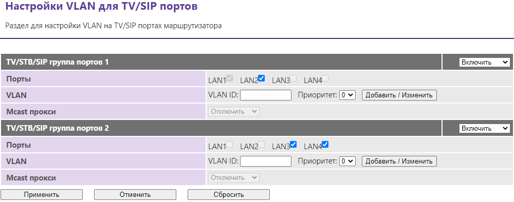
Если ваш интернет провайдер для настройки телевидения и телефонии предоставляет вам VLAN (VLAN ID, 802.11q), то для телевизионной приставки и SIP-телефона вы можете настроить на маршрутизаторе отдельные группы портов.
Откройте меню Настройки сети – Настройки VLAN:
- Выберите группу, например, TV/STB/SIP группа портов 1 и активируйте опцией Включить. Выберите порт(ы), куда подключена телевизионная приставка или SIP-телефон. Укажите номер VLAN в поле VLAN ID и нажмите Добавить/Изменить, затем Применить.
- В случае, если оператор связи предполагает использование неуправляемого коммутатора или требует «прозрачного» подключения телевизионной приставки или SIP-телефона без маршрутизации и NAT (подключение в режиме сетевого моста), то поле VLAN ID нужно оставить пустым, а затем нажать Применить.
Если все выполнено верно, то в меню Настройки коммутатора настроенный сетевой интерфейс изменит своё имя на TV/SIP порт 1.
Два интерфейса с применением VLAN ID или в режиме сетевого моста могут работать только одновременно.
Чтобы помочь вам лучше понять содержимое этого документа, компания Huawei перевела его на разные языки, используя машинный перевод, отредактированный людьми.
Примечание: даже самые передовые программы машинного перевода не могут обеспечить качество на уровне перевода, выполненного профессиональным переводчиком.
Компания Huawei не несет ответственность за точность перевода и рекомендует ознакомиться с документом на английском языке (по ссылке, которая была предоставлена ранее).
Configuring Multicast-to-Unicast Conversion
Context
You can enable the function of converting multicast packets to unicast packets in scenarios that have high requirements on multicast stream transmission, such as a high-definition video on-demand scenario.
After the function is enabled, an AP listens on Report and Leave packets to maintain multicast-to-unicast entries. When sending multicast packets to the client, the AP converts the multicast packets to unicast packets based on the multicast-to-unicast entries to improve multicast stream transmission efficiency.
After adaptive multicast-to-unicast conversion is enabled, when the air interface performance becomes a bottleneck during multicast-to-unicast conversion, an AP automatically switches the multicast group containing the minimum number of STAs to the multicast mode. After the air interface performance is improved and keeps being improved for a period of time, the AP automatically switches the multicast group containing the maximum number of STAs to the unicast mode. In this way, the air interface performance is automatically adjusted without manual intervention, improving wireless user experience.
Procedure
- Run system-view
The system view is displayed.
- Run wlan
The WLAN view is displayed.
- Run traffic-profile name profile-name
A traffic profile is
created, and the traffic profile view is displayed.By default,
the system provides the traffic profile default. - Run traffic-optimize multicast-unicast enable
Multicast-to-unicast conversion is enabled in
the traffic profile.By default, the function of converting multicast packets to unicast packets is disabled in a traffic profile.
- (Optional) Run undo traffic-optimize multicast-unicast dynamic-adaptive disable
Adaptive multicast-to-unicast conversion is enabled.
By default, adaptive multicast-to-unicast conversion is enabled in a traffic profile.
- Run quit
Return to the WLAN view.
- Run vap-profile name profile-name
The VAP profile view is displayed.
- Run traffic-profile profile-name
The traffic profile
is bound to the VAP profile.By default, the traffic profile default is bound to a VAP profile.
Verifying the Configuration
-
Run the display
traffic-profile { all | name profile-name } command to check
the multicast-to-unicast configuration in a traffic profile.
Updated: 2021-12-20
№ документа:EDOC1100195158
Просмотры:974375
Загрузки: 628
Average rating:
This Document Applies to these Products