На чтение 8 мин Просмотров 10.8к.

Кристина Горбунова
Высшее образование по специальности “Информационные системы”. В сфере более 7 лет, занимается разработкой сайтов на WordPress и Tilda.
Задать вопрос
При подключении к интернету у новичков часто возникает вопрос, что такое MTU в настройках роутера и как изменить этот параметр. Мы расскажем, как определить оптимальное значение этой характеристики и когда не стоит изменять максимальный размер полезного блока данных в пакете.
Содержание
- Что такое MTU и из чего складывается параметр
- Определяем оптимальное значение
- Установка MTU в роутере
- ASUS
- TP-Link
- D-Link
- Zyxel
- Keenetic
- Netis
- Tenda
- Upvel
- Mercusys
- Настройка на компьютере
- Что будет, если установить некорректное значение
Что такое MTU и из чего складывается параметр
В интернете информация передается в виде небольших пакетов данных. Каждый блок содержит служебную информацию – заголовок (header). Он нужен для определения типа пересылаемых данных, количества отправляемых пакетов и т. д. Величина передаваемого блока данных ограничена конкретным количеством байт.
Maximum transmission unit (MTU) – максимальное количество байт, которое сможет передать роутер без фрагментации. Чем больше этот параметр, тем выше скорость интернета. Для интерфейса Ethernet типовое значение этой характеристики – 1500. Реальная величина параметра MTU чуть меньше в пределах 1460-1480 байт.
Пример работы MTU. Роутеру нужно передать файл размером 9000 байт. Величина МТУ – 1470. Устройства фрагментирует передаваемую информацию на 7 частей – 6 фрагментов величиной 1470 байт и 1 фрагмент 180 байт.
Многие модели роутеров определяют МТУ самостоятельно при подключении к ПК и сети, но не всегда автоматически установленная величина совпадает с параметрами интернета.
За счет правильно настроенного значения МТУ можно:
- увеличить канал передачи, чтобы к нему одновременно смогли подключаться разные сетевые службы, приложения;
- сократить количество поврежденных пакетов при передаче данных;
- снизить нагрузку на канал передачи и увеличить скорость интернета.
Внимание! К изменению МТУ приступайте только при наличии проблем с интернетом или какими-то сетевыми службами. Если скорость соединения нормальная и сайты грузятся без проблем, лучше этот параметр не менять.
Современные ОС автоматически вычисляют оптимальное значение максимального размера блока данных или берут его из настроек роутера. Пользователи могут настроить МТУ самостоятельно с помощью командной строки.
Определяем оптимальное значение
Самый простой путь поиска оптимальной величины МТУ – узнать у провайдера. Большинство компаний предоставляют клиентам все настройки сети (VPI, VCI, имя IP-сервера). Если такой информации провайдер не предоставил, определить параметр можно самостоятельно.
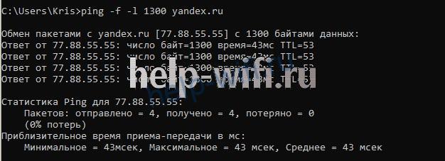
Найти оптимальное значение MTU можно при помощи команды ping. Пропинговать можно любой ресурс.
Для этого отройте командную строку и введите команду:
ping -f -l 1300 yandex.ru
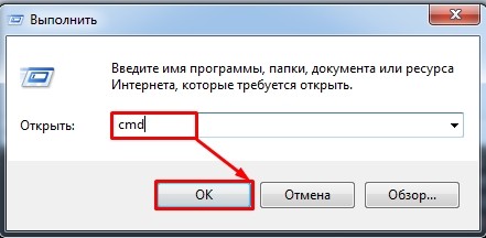
Для открытия командной строки нажмите Win+R. В появившемся окне введите cmd, а затем нажмите на Enter. Откроется консоль с черным экраном. Это и есть командная строка.
В введенной команде 1300 – размер пакета в байтах. Далее увеличивайте его, пока в командной строке не появится ошибка «Требуется фрагментация пакета, но установлен запрещающий флаг». Значение пакета, предшествующее появлению сообщения, равно максимальному количеству передаваемой информации.
Для нашего соединения этот параметр составляет 1432 байта. Если установить значение 1433, то появится ошибка. 1432 – это максимальна величина данных, передаваемая без заголовков (maximum segment size или MSS).

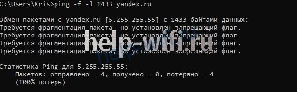
Для того, чтобы узнать размер MTU в байтах, прибавьте 28 к максимальному размеру пакета. В нашем случае это 1460 (1432+28). Это значение и нужно выставить в МТУ роутера.
Установка MTU в роутере
Сменить стандартное значение MTU можно в настройках роутерах. Для этого введите DNS или IP адрес устройства в адресную строку браузера. Он обычно указан на нижней части корпуса.
Самые популярные адреса:
- 192.168.0.1;
- 192.168.1.1.
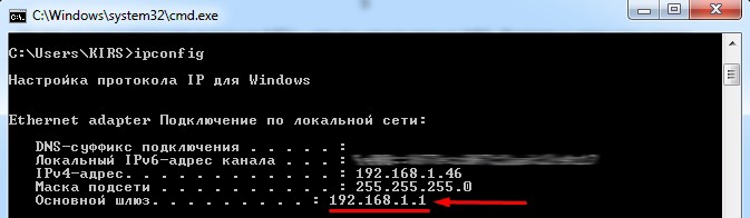
Еще один способ определения адреса – ввести в командную строку ipconfig.
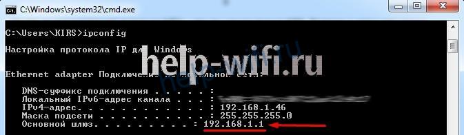
IP роутера 192.168.1.1. После того как узнали адрес для входа, вводим его в адресной строке браузера. Следующим шагом нужно будет ввести логин и пароль администратора. По умолчанию это «admin» в оба поля.
Далее процесс настройки зависит от модели используемого устройства.
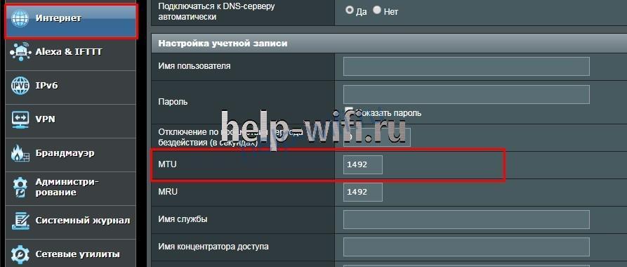
ASUS
Откройте вкладку «Дополнительные настройки» и найдите там раздел «Интернет» или «Wan».
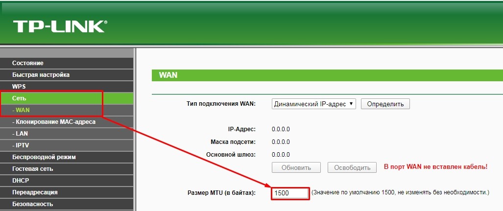
TP-Link
В старой прошивке роутеров откройте раздел «Сеть». В нижней части страницы вкладки WAN будет указан размер МТУ. Для замены просто введите новое значение и нажмите на кнопку «Сохранить».

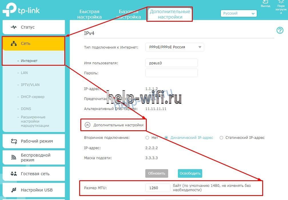
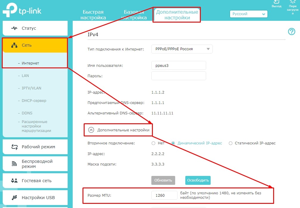
В новых роутерах нужно перейти в раздел «Дополнительные настройки», открыть вкладку «Сеть» и открыть пункт «Интернет». В блоке «Дополнительные настройки» будет указан параметр MTU в роутере. После изменения параметров нажмите на кнопку «Сохранить». Новые настройки вступят в силу после перезагрузки роутера.
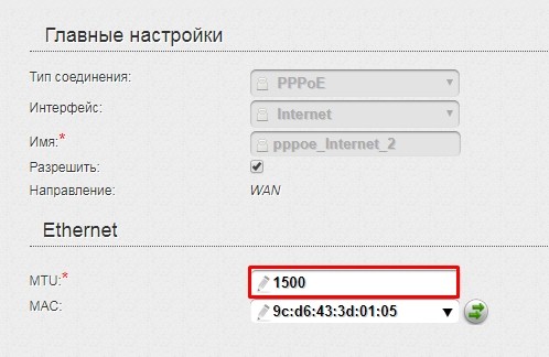
D-Link
Для настройки максимального размера блока данных откройте раздел «Сеть» подпункт «WAN». Выберите используемое подключение к интернету.

В появившемся списке настроек найдите пункт «MTU».

Zyxel
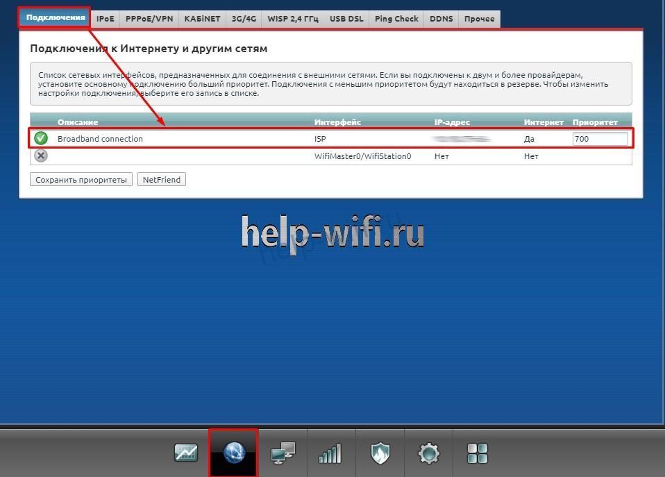
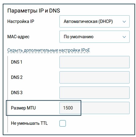
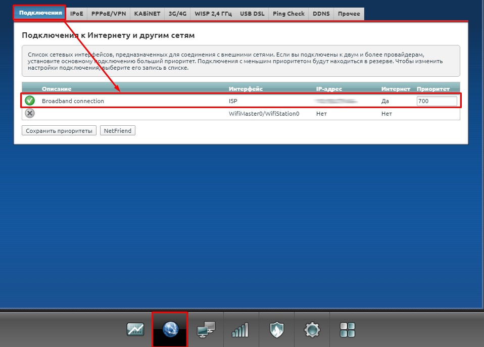
- Откройте раздел «Интернет» и откройте вкладку «Подключения». Выберите активное подключение или создайте новое.

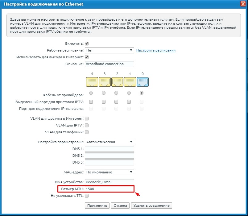
- Найдите параметр «Размер MTU». Введите свое значение.

- Нажмите на кнопку «Применить» для сохранения параметров.

Keenetic
Чтобы изменить параметр MTU:
- В разделе «Интернет» откройте вкладку «Проводной».
- Найдите блок «Аутентификация у провайдера (PPPoE / PPTP / L2TP)» или «Параметры IP и DNS».
- Откройте дополнительные настройки. Найдите пункт «Размер MTU».


Netis
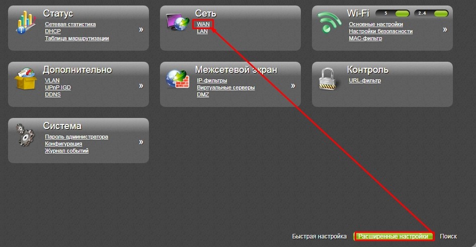
Нажмите на кнопку Advanced.
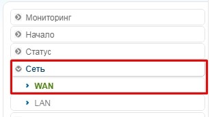
Откройте меню «Сеть». Выберите подпункт «Wan».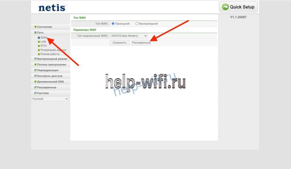
Чтобы поставить значение MTU в роутере Netis, откройте расширенные настройки WAN-соединения.
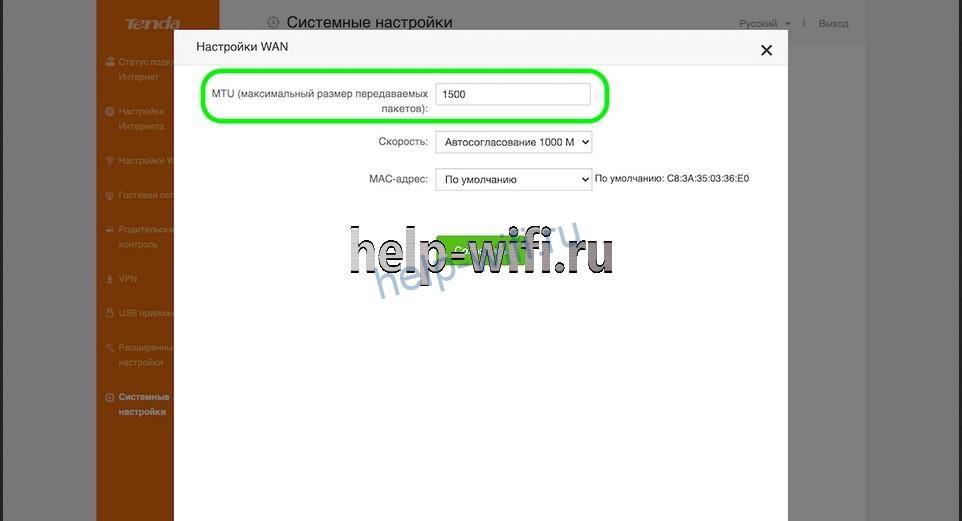
Tenda
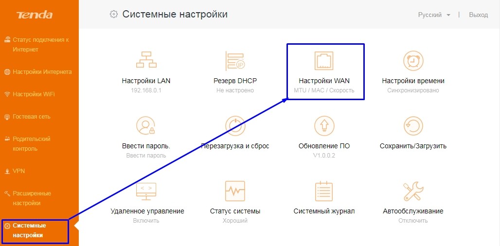
Откройте раздел «Системные настройки». Найдите там пункт «Настройки WAN».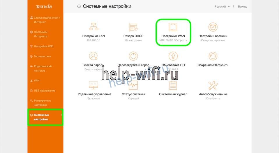
В открывшемся окне на первой строчке находится «Максимальный размер передаваемых пакетов». Его нужно уменьшить или увеличить.
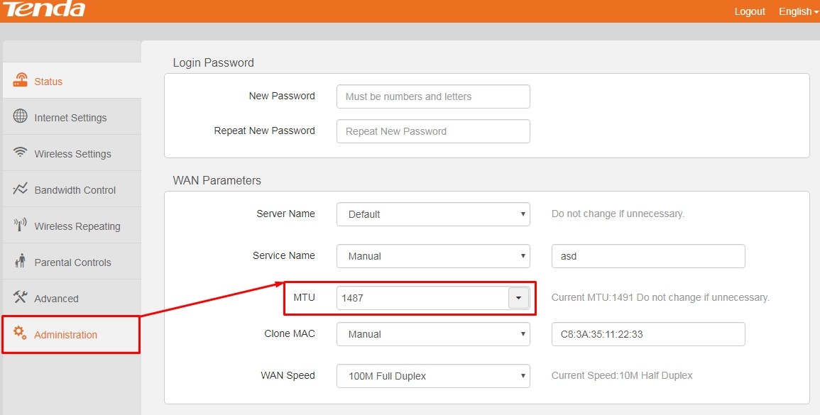
В роутерах Tenda с обновленной прошивкой нужные настройки расположены в разделе «Administration».
Upvel
Откройте раздел «Настройки», выберите там «Интерфейс WAN».

Mercusys
Откройте меню «Расширенные настройки», перейдите в пункт «Настройки WAN».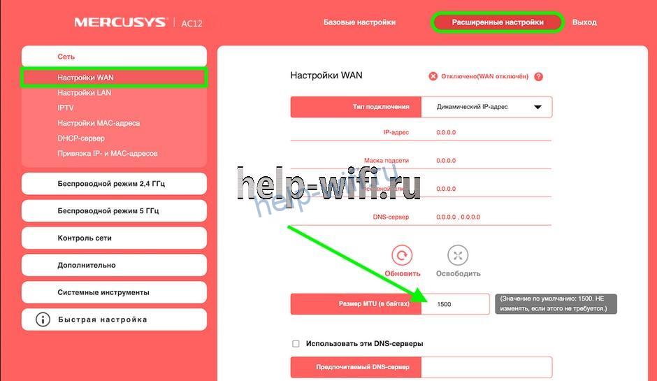
Настройка на компьютере
Поменять MTU в Windows 7, 10 можно за несколько минут.
Пошагово процесс выглядит так:
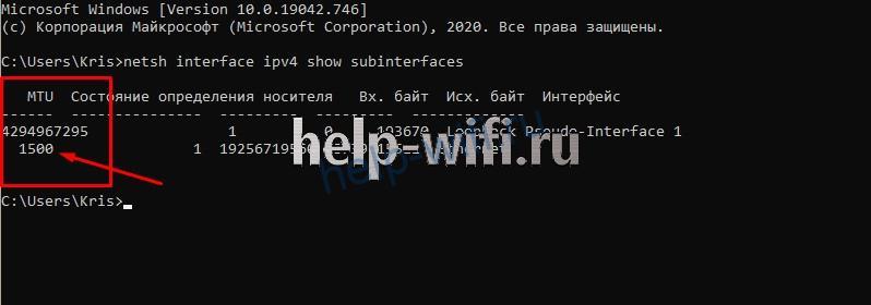
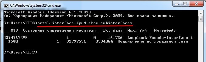
- Определите текущую величину МТУ. Запустите командную строку. Введите команду «netsh interface ipv4 show subinterfaces». На экране появится таблица, в которой видно, что значение параметра 1500.

- Установите новое значение максимального размера передаваемых пакетов. Для этого введите команду «netsh interface ipv4 set subinterface “Ethernet” mtu=1300 store=persistent», где 1300 – новая величина передаваемого блока данных.
- Проверить ввод новых настроек. Необходимо снова ввести команду «netsh interface ipv4 show subinterfaces». Проверка считается успешной, если значение изменилось на 1300. Если значение осталось прежним, то снова введите команду из пункта 2.
После сохранения этих настроек с компьютера будут отправляться пакеты, максимальный размер которых ограничен на IP-уровне 1300 байтами. Но на MAC-уровне их величина будет равна 1314 байт. Отправка пакетов данных большего размера осуществляться не будет.
В ОС семейства Linux тоже можно изменить МТУ. Для этого запустите консоль комбинацией Ctrl+Alt+F1.
Дальнейший порядок действий:
- Определите величину МТУ с помощью команды ip link.
- Установите новое значение максимального передаваемого блока данных с помощью команды «ip link set dev eth0 mtu 1200», где 1200 – нужный размер МТУ.
С помощью команды происходит временная замена значения максимальной величины передаваемых пакетов на 1200. После перезагрузки восстановится значение по умолчанию. Для того, чтобы сделать новую величину постоянной, отредактируйте файл /etc/network/interfaces. К описанию нужного интерфейса (eth0) добавьте отдельной строкой mtu 1200.
После сохранения настроек выполните команду ifdown $eth0 && ifup $eth0, где eth0 – наименование интерфейса.
Что будет, если установить некорректное значение
Если на маршрутизаторе поменять значение МТУ на некорректное, возникнут проблемы с интернетом. При маленьком размере пакетов во время загрузки некоторых сайтов будут появляться ошибки, увеличится пинг. Установить значение МТУ больше стандартного не позволит прошивка роутера. Ограничение на максимальный размер пакета данных есть во всех современных модемах и маршрутизаторах.
Если пользователь все-таки сможет установить большой размер параметра, интернет работать не будет.
From Wikipedia, the free encyclopedia
In computer networking, the maximum transmission unit (MTU) is the size of the largest protocol data unit (PDU) that can be communicated in a single network layer transaction.[1] The MTU relates to, but is not identical to the maximum frame size that can be transported on the data link layer, e.g., Ethernet frame.
Larger MTU is associated with reduced overhead. Smaller MTU values can reduce network delay. In many cases, MTU is dependent on underlying network capabilities and must be adjusted manually or automatically so as to not exceed these capabilities. MTU parameters may appear in association with a communications interface or standard. Some systems may decide MTU at connect time, e.g. using Path MTU Discovery.
Applicability[edit]
MTUs apply to communications protocols and network layers. The MTU is specified in terms of bytes or octets of the largest PDU that the layer can pass onwards. MTU parameters usually appear in association with a communications interface (NIC, serial port, etc.). Standards (Ethernet, for example) can fix the size of an MTU; or systems (such as point-to-point serial links) may decide MTU at connect time.
Underlying data link and physical layers usually add overhead to the network layer data to be transported, so for a given maximum frame size of a medium, one needs to subtract the amount of overhead to calculate that medium’s MTU. For example, with Ethernet, the maximum frame size is 1518 bytes, 18 bytes of which are overhead (header and frame check sequence), resulting in an MTU of 1500 bytes.
Tradeoffs[edit]
A larger MTU brings greater efficiency because each network packet carries more user data while protocol overheads, such as headers or underlying per-packet delays, remain fixed; the resulting higher efficiency means an improvement in bulk protocol throughput. A larger MTU also requires processing of fewer packets for the same amount of data. In some systems, per-packet-processing can be a critical performance limitation.
However, this gain is not without a downside. Large packets occupy a slow link for more time than a smaller packet, causing greater delays to subsequent packets, and increasing network delay and delay variation. For example, a 1500-byte packet, the largest allowed by Ethernet at the network layer, ties up a 14.4k modem for about one second.
Large packets are also problematic in the presence of communications errors. If no forward error correction is used, corruption of a single bit in a packet requires that the entire packet be retransmitted, which can be costly. At a given bit error rate, larger packets are more susceptible to corruption. Their greater payload makes retransmissions of larger packets take longer. Despite the negative effects on retransmission duration, large packets can still have a net positive effect on end-to-end TCP performance.[2]
Internet protocol[edit]
The Internet protocol suite was designed to work over many different networking technologies, each of which may use packets of different sizes. While a host will know the MTU of its own interface and possibly that of its peers (from initial handshakes), it will not initially know the lowest MTU in a chain of links to other peers. Another potential problem is that higher-level protocols may create packets larger than even the local link supports.
IPv4 allows fragmentation which divides the datagram into pieces, each small enough to accommodate a specified MTU limitation. This fragmentation process takes place at the internet layer. The fragmented packets are marked so that the IP layer of the destination host knows it should reassemble the packets into the original datagram.
All fragments of a packet must arrive for the packet to be considered received. If the network drops any fragment, the entire packet is lost.
When the number of packets that must be fragmented or the number of fragments is great, fragmentation can cause unreasonable or unnecessary overhead. For example, various tunneling situations may exceed the MTU by very little as they add just a header’s worth of data. The addition is small, but each packet now has to be sent in two fragments, the second of which carries very little payload. The same amount of payload is being moved, but every intermediate router has to forward twice as many packets.
The Internet Protocol requires that hosts must be able to process IP datagrams of at least 576 bytes (for IPv4) or 1280 bytes (for IPv6). However, this does not preclude link layers with an MTU smaller than this minimum MTU from conveying IP data. For example, according to IPv6’s specification, if a particular link layer cannot deliver an IP datagram of 1280 bytes in a single frame, then the link layer must provide its own fragmentation and reassembly mechanism, separate from the IP fragmentation mechanism, to ensure that a 1280-byte IP datagram can be delivered, intact, to the IP layer.
MTUs for common media[edit]
In the context of Internet Protocol, MTU refers to the maximum size of an IP packet that can be transmitted without fragmentation over a given medium. The size of an IP packet includes IP headers but excludes headers from the link layer. In the case of an Ethernet frame this adds an overhead of 18 bytes, or 22 bytes with an IEEE 802.1Q tag for VLAN tagging or class of service.
The MTU should not be confused with the minimum datagram size that all hosts must be prepared to accept. This is 576 bytes for IPv4[3] and of 1280 bytes for IPv6.[4]
| Media for IP transport | Maximum transmission unit (bytes) | Notes |
|---|---|---|
| Internet IPv4 path MTU | At least 68,[5] max of 64 KiB[6] | Systems may use Path MTU Discovery[7] to find the actual path MTU. Routing from larger MTU to smaller MTU causes IP fragmentation. |
| Internet IPv6 path MTU | At least 1280,[8] max of 64 KiB, but up to 4 GiB with optional jumbogram[9] | Systems must use Path MTU Discovery[10] to find the actual path MTU. |
| X.25 | Minimal 576 (sending) or 1600 (receiving)[11] | |
| Ethernet v2 | 1500[12] | Nearly all IP over Ethernet implementations use the Ethernet II frame format. |
| Ethernet with LLC and SNAP | 1492[13] | |
| Ethernet jumbo frames | 1501 – 9202[14] or more[15] | The limit varies by vendor. For correct interoperation, frames should be no larger than the maximum frame size supported by any device on the network segment.[16] Jumbo frames are usually only seen in special-purpose networks. |
| PPPoE v2 | 1492[17] | Ethernet II MTU (1500) less PPPoE header (8) |
| DS-Lite over PPPoE | 1452 | Ethernet II MTU (1500) less PPPoE header (8) and IPv6 header (40) |
| PPPoE jumbo frames | 1493 – 9190 or more[18] | Ethernet Jumbo Frame MTU (1501 — 9198) less PPPoE header (8) |
| IEEE 802.11 Wi-Fi (WLAN) | 2304[19] | The maximum MSDU size is 2304 before encryption. WEP will add 8 bytes, WPA-TKIP 20 bytes, and WPA2-CCMP 16 bytes. |
| Token Ring (802.5) | 4464 | |
| FDDI | 4352[7] |
Ethernet maximum frame size[edit]
The IP MTU and Ethernet maximum frame size are configured separately. In Ethernet switch configuration, MTU may refer to Ethernet maximum frame size. In Ethernet-based routers, MTU normally refers to the IP MTU. If jumbo frames are allowed in a network, the IP MTU should also be adjusted upwards to take advantage of this.
Since the IP packet is carried by an Ethernet frame, the Ethernet frame has to be larger than the IP packet. With the normal untagged Ethernet frame overhead of 18 bytes, the Ethernet maximum frame size is 1518 bytes. If a 1500 byte IP packet is to be carried over a tagged Ethernet connection, the Ethernet frame maximum size needs to be 1522 due to the larger size of an 802.1Q tagged frame. 802.3ac increases the standard Ethernet maximum frame size to accommodate this.
Path MTU Discovery[edit]
The Internet Protocol defines the path MTU of an Internet transmission path as the smallest MTU supported by any of the hops on the path between a source and destination. Put another way, the path MTU is the largest packet size that can traverse this path without suffering fragmentation.
Path MTU Discovery is a technique for determining the path MTU between two IP hosts, defined for both IPv4[20] and IPv6[21]. It works by sending packets with the DF (don’t fragment) option in the IP header set. Any device along the path whose MTU is smaller than the packet will drop such packets and send back an ICMP Destination Unreachable (Datagram Too Big) message which indicates its MTU. This information allows the source host to reduce its assumed path MTU appropriately. The process repeats until the MTU becomes small enough to traverse the entire path without fragmentation.
Standard Ethernet supports an MTU of 1500 bytes and Ethernet implementation supporting jumbo frames, allow for an MTU up to 9000 bytes. However, border protocols like PPPoE will reduce this. Path MTU Discovery exposes the difference between the MTU seen by Ethernet end-nodes and the Path MTU.
Unfortunately, increasing numbers of networks drop ICMP traffic (for example, to prevent denial-of-service attacks), which prevents path MTU discovery from working. Packetization Layer Path MTU Discovery[22][23] is a Path MTU Discovery technique which responds more robustly to ICMP filtering. In an IP network, the path from the source address to the destination address may change in response to various events (load-balancing, congestion, outages, etc.) and this could result in the path MTU changing (sometimes repeatedly) during a transmission, which may introduce further packet drops before the host finds a new reliable MTU.
A failure of Path MTU Discovery carries the possible result of making some sites behind badly configured firewalls unreachable. A connection with mismatched MTU may work for low-volume data but fail as soon as a host sends a large block of data. For example, with Internet Relay Chat a connecting client might see the initial messages up to and including the initial ping (sent by the server as an anti-spoofing measure), but get no response after that. This is because the large set of welcome messages sent at that point are packets that exceed the path MTU. One can possibly work around this, depending on which part of the network one controls; for example one can change the MSS (maximum segment size) in the initial packet that sets up the TCP connection at one’s firewall.
In other contexts[edit]
MTU is sometimes used to describe the maximum PDU sizes in communication layers other than the network layer.
- Cisco Systems and MikroTik use L2 MTU for the maximum frame size.[24][25]
- Dell/Force10 use MTU for the maximum frame size.[26]
- Hewlett-Packard used just MTU for the maximum frame size including the optional IEEE 802.1Q tag.[27]
- Juniper Networks use several MTU terms: Physical Interface MTU (L3 MTU plus some unspecified protocol overhead), Logical Interface MTU (consistent with IETF MTU) and Maximum MTU (maximum configurable frame size for jumbo frames).[28]
The transmission of a packet on a physical network segment that is larger than the segment’s MTU is known as jabber. This is almost always caused by faulty devices.[29] Network switches and some repeater hubs have a built-in capability to detect when a device is jabbering.[30][31]
References[edit]
- ^ RFC 791. p. 25. doi:10.17487/RFC0791.
- ^ Murray, David; Terry Koziniec; Kevin Lee; Michael Dixon (2012). «Large MTUs and internet performance». 2012 IEEE 13th International Conference on High Performance Switching and Routing. pp. 82–87. doi:10.1109/HPSR.2012.6260832. ISBN 978-1-4577-0833-6. S2CID 232321.
- ^ RFC 791. p. 24. doi:10.17487/RFC0791.
Every internet destination must be able to receive a datagram of 576 octets either in one piece or in fragments to be reassembled.
- ^ RFC 2460. p. 13. doi:10.17487/RFC2460.
- ^ RFC 791. p. 24. doi:10.17487/RFC0791.
Every internet module must be able to forward a datagram of 68 octets without further fragmentation.
- ^ RFC 791. p. 12. doi:10.17487/RFC0791.
Total Length is the length of the datagram, measured in octets, including internet header and data. This field allows the length of a datagram to be up to 65,535 octets.
- ^ a b RFC 1191. doi:10.17487/RFC1191.
- ^ RFC 2460
- ^ RFC 2675, p. 1, «The IPv6 header [IPv6] has a 16-bit Payload Length field and, therefore, supports payloads up to 65,535 octets long. This document specifies an IPv6 hop-by-hop option, called the Jumbo Payload option, that carries a 32-bit length field in order to allow transmission of IPv6 packets with payloads between 65,536 and 4,294,967,295 octets in length. Packets with such long payloads are referred to as ‘jumbograms’.»
- ^ RFC 6145
- ^ RFC 1356
- ^
Network Working Group of the IETF,
RFC 894: A Standard for the Transmission of IP Datagrams over Ethernet Networks,
Page 1,
«The maximum length of the data field of a packet sent over an Ethernet is 1500 octets, thus the maximum length of an IP datagram sent over an Ethernet is 1500 octets.»,
ERRATA - ^ IEEE 802.3[page needed]
- ^ Scott Hogg (2013-03-06), Jumbo Frames, Network World, retrieved 2013-08-05,
Most network devices support a jumbo frame size of 9216 bytes.
- ^ Juniper Networks (2020-03-23), Physical Interface Properties, retrieved 2020-05-01
- ^ Joe St Sauver (2003-02-04). «Practical Issues Associated With 9K MTUs» (PDF). uoregon.edu. p. 67. Retrieved 2016-12-15.
you still need to insure that ALL upstream Ethernet switches, including any switches in your campus core, are ALSO jumbo frame capable
- ^ RFC 2516 with the standard Ethernet MTU of 1500 bytes; extensions exist
- ^ RFC 4638
- ^ 802.11-2012, page 413, section 8.3.2.1
- ^ J. Mogul; S. Deering (November 1990). Path MTU Discovery. Network Working Group. doi:10.17487/RFC1191. RFC 1191. Draft Standard. Obsoletes RFC 1063.
- ^ J. McCann; S. Deering; J. Mogul (July 2017). R. Hinden (ed.). Path MTU Discovery for IP version 6. IETF. doi:10.17487/RFC8201. STD 87. RFC 8201. Internet Standard. Obsoletes RFC 1981.
- ^ M. Mathis; J. Heffner (March 2007). Packetization Layer Path MTU Discovery. Network Working Group. doi:10.17487/RFC4821. RFC 4821. Proposed Standard. Updated by RFC 8899.
- ^ G. Fairhurst; T. Jones; M. Tüxen; I. Rüngeler; T. Völker (September 2020). Packetization Layer Path MTU Discovery for Datagram Transports. IETF. doi:10.17487/RFC8899. ISSN 2070-1721. RFC 8899. Proposed Standard. Updates RFC 4821, 4960, 6951, 8085 and 8261.
- ^ «Configure and Verify Maximum Transmission Unit on Cisco Nexus Platforms». Cisco. 2016-11-29. Document ID:118994. Retrieved 2017-01-04.
- ^ «MTU in RouterOS». MikroTik. 2022-07-08. Retrieved 2022-09-02.
- ^ «How to configure MTU (Maximum Transmission Unit) for Jumbo Frames on Dell Networking Force10 switches». Dell. 2016-06-02. Article ID: HOW10713. Retrieved 2017-01-06.
- ^ «Jumbo Frames». HP Networking 2910al Switches Management and Configuration Guide. Hewlett-Packard. November 2011. P/N 5998-2874.
- ^ «SRX Series Services Gateways for the Branch Physical Interface Modules Reference: MTU Default and Maximum Values for Physical Interface Modules«. Juniper. 2014-01-03. Retrieved 2017-01-04.
- ^ jabber, The Network Encyclopedia, retrieved 2016-07-28
- ^ show interfaces, Juniper Networks, retrieved 2016-07-28
- ^ IEEE 802.3 27.3.1.7 Receive jabber functional requirements
External links[edit]
- Marc Slemko (January 18, 1998). «Path MTU Discovery and Filtering ICMP». Archived from the original on August 9, 2011. Retrieved 2007-09-02.
- Tweaking your MTU / RWin for Orange Broadband Users
- How to set the TCP MSS value using iptables
- mturoute – a console utility for debugging mtu problems
Всем привет! Начнем, пожалуй, с вопроса – а что же такое MTU? MTU (от английского Maximum transmission unit) – это максимальный объем в пакете, который может передавать в той или иной сетевой среде. Как вы знаете, все данные передаются определенными пакетами – будь это интернет, Wi-Fi или локальная сеть дома. Все как на почте – почтальон не может переносить больше определенного веса.
Конечно, тут идут и некоторые ограничения. Например, в PPPoE обычно используется 1492 байта. При Ethernet подключении 1500 байта, а в беспроводной сети MTU равен 2304. Если же сетевому устройству нужно передать куда больше информации, то все делится как раз на эти MTU блоки.
Размер MTU зачастую определяется самим отправляющим устройством. MTU в настройках роутера также задается по умолчанию значением заданным разработчиками. Если говорить проще, то происходит следующее:
- Отправляющее устройство режет всю информацию на отдельные MTU куски и отправляет их по каналу связи.
- Принимающее устройство собираем все эти куски в целый кусок, отправленной информации.
Также нужно знать, что в размер MTU входит:
- MSS (Maximum Segment Size) – это основной блок данных.
- Заголовок IP.
- Заголовок ICMP
К чему может привести неправильное значение MTU? Если на роутере, который чаще всего является шлюзом между интернетом и локальной сетью, выставлено неправильное значение, то могут наблюдаться проблемы со связью и интернетом. Например, нельзя зайти на какой-то сайт, некоторые службы в локальной сети перестают работать. Но само значение можно выставить вручную в настройках маршрутизатора.
Также вы можете встретить параметр MRU (maximum receive unit) – это максимальный размер пакета, который может принять устройство. Все по аналогии с MTU. Далее я расскажу, как узнать оптимальный размер MTU в вашей сети и как установить это значение в роутере.
ВНИМАНИЕ! Это нужно делать только в том случае, если у вас наблюдаются проблемы с интернетом, сетью или какими-то сетевыми службами. Если у вас все в порядке, то лучше ничего не делать, так как дальнейшие действия могут привести к ухудшению связи.
Содержание
- Определение идеального MTU
- Установка MTU в роутере
- Zyxel Keenetic
- TP-Link
- D-Link
- ASUS
- LinkSys
- Netis
- Tenda
- Задать вопрос автору статьи
Способ достаточно простой – мы будем использовать встроенную утилиту в Windows «ping» с помощью командной строки. Нажмите на клавиши «Win» (находится в нижнем ряду между «Ctrl» и «Alt») и английскую «R».

В окошке введите команду «cmd» и нажмите «ОК». Командную строку также можно запустить через «Пуск», введя в поисковую строку эти три буквы.
Для начала давайте узнаем, какой MTU у нас стоит по умолчанию. Для этого вводим команду:
netsh interface ipv4 show subinterfaces
Я подключен по Wi-Fi, поэтому у меня стоит стандартное значение 1500. Если же вы подключены к кабелю провайдера напрямую, то эта команда может вам помочь.
Далее мы будем использовать стандартную команду ping с определенными параметрами. Наша задача взять за основу какое-то определенное значение MTU и увеличивать его до тех пор, пока система не сообщит нам, что нам нужно установить параметр фрагментации или разбиения пакета.
Если говорить проще, то мы будем увеличивать пакет до тех пор, пока он проходит по нашему соединению в интернете. Для примера мы будем пинговать всем известный «google.com», но вы можете взять любой другой сайт:
ping www.google.com -f -l 1440
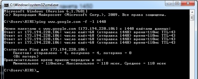
В итоге мы видим, что пакеты с размером в 1440 байтов спокойно отправляются в сеть. Поэтому мы увеличим размер MTU на 1. Немного о команде: значение «-f» – запрещает фрагментировать пакет – это нужно для наших тестов. «-l» (маленькая английская буква «L») – задает размер пакета.
Теперь увеличиваем его на один. Чтобы не прописывать команду постоянно, нажмите на клавиатуре на стрелку вверх, сотрите последнюю цифру и увеличьте её на один:
ping www.google.com -f -l 1441
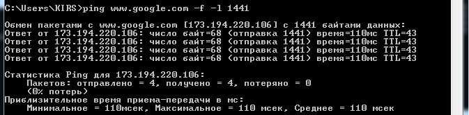
Как видите этот пакет также свободно проходит. В общем проделываем эту процедуру до тех пор, пока вы сами не найдете идеальный параметр для вашей среды. В самом конце вы должны увидеть сообщение:
«Требуется фрагментация пакета, но установлен запрещающий флаг»
В моем случае это 1472, но у вас может быть совершенно другой параметр, так что нужно проводить свои тесты.
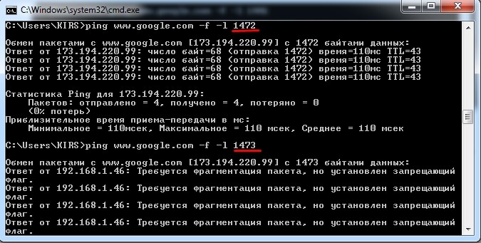
Но это не окончательное значение MTU – это мы нашли только MSS. Поэтому к нему нам нужно прибавить IP и ICMP заголовки. Для этого просто прибавляем ещё 28 байта:
1472 + 28 = 1500
Теперь данное значение можно установить в вашем домашнем роутере.
Установка MTU в роутере
Для начала нам нужно зайти в настройки роутера – для этого нужно ввести IP или DNS адрес в адресную строку любого браузера. Можете попробовать популярные адреса:
- 192.168.1.1
- 192.168.0.1
Адрес можно подсмотреть на этикетке под корпусом. Или ввести в консоль команду:
ipconfig
IP маршрутизатора будет в строке 192.168.1.1.
Далее инструкции могут отличаться в зависимости от модели роутера.
Zyxel Keenetic
Новая прошивка
«Проводной» – «Параметры IP и DNS» (или «Аутентификация у провайдера (PPPoE / PPTP / L2TP)»)
Старая прошивка
Переходим в раздел «Интернета» – далее на вкладке «Подключение» выбираем активный коннект к интернету.
Ищем строку «Размер MTU».
TP-Link
Старая прошивка
«Сеть» – «WAN».
Новая прошивка
«Дополнительные настройки» – «Сеть» – «Интернет» – «Дополнительные настройки».
D-Link
Классическая прошивка
«Сеть» – «WAN».
Новая прошивка
Из списка выбираем активное подключение (через которое идет интернет).

Далее находим параметр MTU.
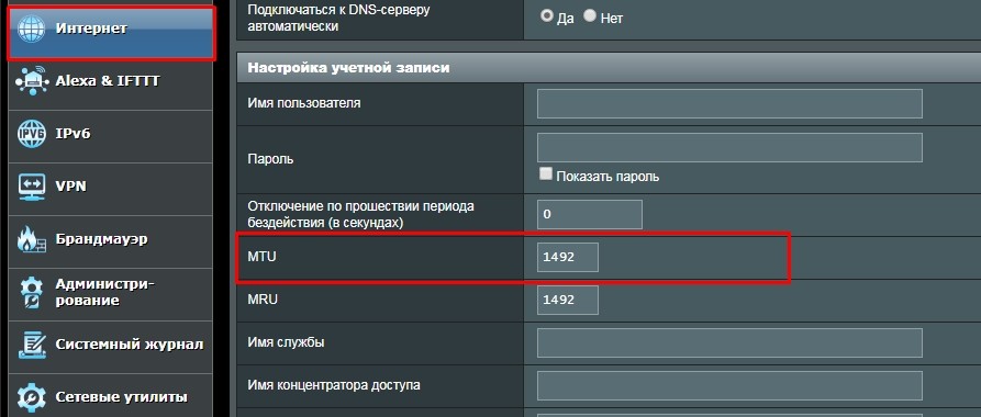
ASUS
Переходим в раздел «Интернет».
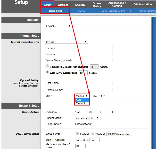
LinkSys
«Setup» – «Basic Setup» – чуть ниже будет строка «MTU». По умолчанию стоит значение «Auto», которое само высчитывает нужное число. Для установки конкретного параметра нужно установить режим «Manual» и вписать найденные через консоль цифры.
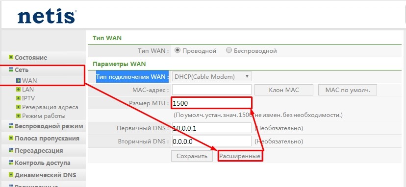
Netis
«Сеть» – «WAN» – нажимаем на кнопку «Расширенные» под вашим подключением.
Tenda
V1-3
«Системные настройки» – «Настройки WAN».
V4
Кликаем на последний раздел «Administration».
![]()
Applies to RouterOS: v3, v4
Summary
The PPPoE (Point to Point Protocol over Ethernet) protocol provides extensive user management, network management and accounting benefits to ISPs and network administrators. Currently PPPoE is used mainly by ISPs to control client connections for xDSL and cable modems as well as plain Ethernet networks. PPPoE is an extension of the standard Point to Point Protocol (PPP). The difference between them is expressed in transport method: PPPoE employs Ethernet instead of serial modem connection.
Generally speaking, PPPoE is used to hand out IP addresses to clients based on authentication by username (and also if required, by workstation) as opposed to workstation only authentication where static IP addresses or DHCP are used. It is advised not to use static IP addresses or DHCP on the same interfaces as PPPoE for obvious security reasons.
The PPPoE client and server work over any Layer2 Ethernet level interface on the router — wireless 802.11 (Aironet, Cisco, WaveLan, Prism, Atheros), 10/100/1000 Mbit/s Ethernet, RadioLan and EoIP (Ethernet over IP tunnel).
Feature list
- PPPoE server and client support;
- Multilink PPP (MLPPP);
- MLPPP over single link (ability to transmit full-sized frames);
- BCP (Bridge Control Protocol) support — allows sending of raw Ethernet frames over PPP links;
- MPPE 128bit RSA encryption;
- pap, chap, mschap v1/v2 authentication;
- RADIUS support for client authentication and accounting.
Note that when RADIUS server is authenticating a user with CHAP, MS-CHAPv1 or MS-CHAPv2, the RADIUS protocol does not use shared secret, it is used only in authentication reply. So if you have a wrong shared secret, RADIUS server will accept the request. You can use /radius monitor command to see bad-replies parameter. This value should increase whenever a client tries to connect.
Supported connections:
- MikroTik RouterOS PPPoE client to any PPPoE server (access concentrator)
- MikroTik RouterOS server (access concentrator) to multiple PPPoE clients (clients are available for almost all operating systems and most routers)
Specifications
- Packages required: ppp
- License required: Level1 (limited to 1 interface) , Level3 (limited to 200 interfaces) , Level4 (limited to 200 interfaces) , Level5 (limited to 500 interfaces) , Level6 (unlimited)
- Submenu level: /interface pppoe-server, /interface pppoe-client
- Standards and Technologies: PPPoE (RFC 2516)
- Hardware usage: PPPoE server may require additional RAM (uses approx. 9KiB (plus extra 10KiB for packet queue, if data rate limitation is used) for each connection) and CPU power. Maximum of 65535 connections is supported.
Quick Setup Guide
To configure MikroTik RouterOS to be a PPPoE client, just add a pppoe-client:
/interface pppoe-client
  add name=pppoe-user-mike user=user password=passwd interface=wlan1 \
  service-name=internet disabled=no
To configure MikroTik RouterOS to be an Access Concentrator (PPPoE Server):
- add an address pool for the clients from 10.1.1.62 to 10.1.1.72;
- add ppp profile;
- add ppp secret (username/password);
- add pppoe server itself.
/ip pool
add name="pppoe-pool" ranges=10.1.1.62-10.1.1.72

/ppp profile
add name="pppoe-profile" local-address=10.1.1.1 remote-address=pppoe-pool

/ppp secret
add name=user password=passwd service=pppoe profile=pppoe-profile

/interface pppoe-server server
add service-name=internet interface=wlan1 default-profile=pppoe-profile disabled=no
PPPoE Operation
Stages
PPPoE has two stages:
- Discovery stage — a client discovers all available access concentrators and selects one of them to establish PPPoE session.This stage has four steps: initialization, offer, request and session confirmation . PPPoE Discovery uses special Ethernet frames with their own Ethernet frame type 0x8863.
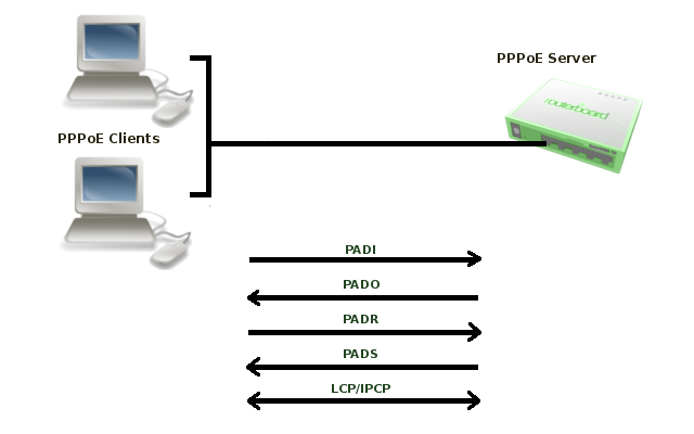
To initiate discovery, PPPoE client sends PADI frame to the broadcast Ethernet address (FF:FF:FF:FF:FF:FF) and optionally may specify a service name.
When server receives PADI frame, it responds with PADO frame to Client’s unicast Ethernet address. There can be more than one server in broadcast range of the client. In such case client collects PADO frames and picks one (in most cases it picks the server which responds first) to start session.
Client sends PADR frame to unicast Ethernet address of the server it chose. If server agrees to set up a session with this particular client, it allocates resources to set up PPP session and assigns Session ID number. This number is sent back to client in PADS frame. When client receives PADS frame, it knows servers mac address and Session ID, it allocates resources and session can begin.
- Session — When discovery stage is completed, both peers know PPPoE Session ID and other peer’s Etehrnet (MAC) address which together defines PPPoE session. PPP frames are encapsulated in PPPoE session frames, which have Ethernet frame type 0x8864.
When server sends confirmation and client receives it, PPP Session stage is started that consists of following steps:- LCP negotiation
- Authentication
- IPCP negotiation — where client is assigned an IP address.
PPPoE server sends Echo-Request packets to the client to determine the state of the session, otherwise server will not be able to determine that session is terminated in cases when client terminates session without sending Terminate-Request packet.
More detailed description of PPPoE protocol can be found in RFC 2516
Used Packet Types
| Packet | Description |
|---|---|
| PADI | PPPoE Active Discovery Initialization The PPPoE client sends out a PADI packet to the broadcast address. This packet can also populate the «service-name» field if a service name has been entered in the dial-up networking properties of the PPPoE client. If a service name has not been entered, this field is not populated |
| PADO | PPPoE Active Discovery Offer The PPPoE server, or Access Concentrator, should respond to the PADI with a PADO if the Access Concentrator is able to service the «service-name» field that had been listed in the PADI packet. If no «service-name» field had been listed, the Access Concentrator will respond with a PADO packet that has the «service-name» field populated with the service names that the Access Concentrator can service. The PADO packet is sent to the unicast address of the PPPoE client |
| PADR | PPPoE Active Discovery Request When a PADO packet is received, the PPPoE client responds with a PADR packet. This packet is sent to the unicast address of the Access Concentrator. The client may receive multiple PADO packets, but the client responds to the first valid PADO that the client received. If the initial PADI packet had a blank «service-name» field filed, the client populates the «service-name» field of the PADR packet with the first service name that had been returned in the PADO packet. |
| PADS | PPPoE Active Discovery Session confirmation When the PADR is received, the Access Concentrator generates a unique session identification (ID) for the Point-to-Point Protocol (PPP) session and returns this ID to the PPPoE client in the PADS packet. This packet is sent to the unicast address of the client. |
| PADT | PPPoE Active Discovery Terminate can be sent anytime after a session is established to indicate that a PPPoE session terminated. It can be sent by either server or client. |
MTU
Typically, the largest Ethernet frame that can be transmitted without fragmentation is 1500 bytes. PPPoE adds another 6 bytes of overhead and PPP field adds two more bytes, leaving 1492 bytes for IP datagram. Therefore max PPPoE MRU and MTU values must not be larger than 1492.
TCP stacks try to avoid fragmentation, so they use an MSS (Maximum Segment Size). By default MSS is chosen as MTU of the outgoing interface minus the usual size of the TCP and IP headers (40 bytes), which results in 1460 bytes for an Ethernet interface. Unfortunately there may be intermediate links with lower MTU which will cause fragmentation. In such case TCP stack performs path MTU discovery. Routers which cannot forward the datagram without fragmentation are supposed to drop packet and send ICMP-Fragmentation-Required to originating host. When host receives such ICMP packet, it tries to lower the MTU.
This should work in the ideal world, however in the real world many routers do not generate fragmentation-required datagrams, also many firewalls drop all ICMP datagrams.
The workaround for this problem is to adjust MSS if it is too big. By default RouterOS adds mangle rules to intercept TCP SYN packets and silently adjust any advertised MSS option so they will be appropriate for the PPPoE link.
Additional information on maximum supported MTUs for RouterBoards are listed here.
PPPoE Client
Sub-menu: /interface pppoe-client
Properties
| Property | Description |
|---|---|
| ac-name (string; Default: «») | Access Concentrator name, this may be left blank and the client will connect to any access concentrator on the broadcast domain |
| add-default-route (yes|no; Default: no) | Enable/Disable whether to add default route automatically |
| allow (mschap2|mschap1|chap|pap; Default: mschap2,mschap1,chap,pap) | allowed authentication methods, by default all methods are allowed |
| default-route-distance (byte [0..255]; Default:1) | sets distance value applied to auto created default route, if add-default-route is also selected |
| dial-on-demand (yes|no; Default: no) | connects to AC only when outbound traffic is generated. If selected, then route with gateway address from 10.112.112.0/24 network will be added while connection is not established. |
| interface (string; Default: ) | interface name on which client will run |
| keepalive-timeout (integer; Default:60) | Sets keepalive timeout in seconds. |
| max-mru (integer; Default: 1460) | Maximum Receive Unit |
| max-mtu (integer; Default: 1460) | Maximum Transmission Unit |
| mrru (integer: 512..65535|disabled; Default: disabled) | maximum packet size that can be received on the link. If a packet is bigger than tunnel MTU, it will be split into multiple packets, allowing full size IP or Ethernet packets to be sent over the tunnel. Read more >> |
| name (string; Default: pppoe-out[i]) | name of the PPPoE interface, generated by RouterOS if not specified |
| password (string; Default: ) | password used to authenticate |
| profile (string; Default: default) | default profile for the connection defined in /ppp profiles |
| service-name (string; Default: «») | specifies the service name set on the access concentrator, can be left blank to connect to any PPPoE server |
| use-peer-dns (yes|no; Default: no) | enable/disable getting DNS settings from the peer |
| user (string; Default: «») | username used for authentication |
Status
Command /interface pppoe-client monitor will display current PPPoE status.
Available read only properties:
| Property | Description |
|---|---|
| ac-mac (MAC address) | MAC address of the access concentrator (AC) the client is connected to |
| ac-name (string) | name of the Access Concentrator |
| active-links (integer) | Number of bonded MLPPP connections, (‘1’ if not using MLPPP) |
| encoding (string) | encryption and encoding (if asymmetric, separated with ‘/’) being used in this connection |
| local-address (IP Address) | IP Address allocated to client |
| remote-address (IP Address) | Remote IP Address allocated to server (ie gateway address) |
| mru (integer) | effective MRU of the link |
| mtu (integer) | effective MTU of the link |
| service-name (string) | used service name |
| status (string) | current link status. Available values are:
|
| uptime (time) | connection time displayed in days, hours, minutes and seconds |
Scanner
Starting from v3.21 RouterOS has new tool — PPPoE Scanner. It allows you to scan all active PPPoE servers in broadcast domain.
Command to run scanner is as follows /interface pppoe-client scan <interface>
Available read only properties:
| Property | Description |
|---|---|
| service (string) | Service name configured on server |
| mac-address (MAC) | Mac address of detected server |
| ac-name (string) | name of the Access Concentrator |
Notes
Note for Windows. Some connection instructions may use the form where the «phone number», such as «MikroTik_AC\mt1», is specified to indicate that «MikroTik_AC» is the access concentrator name and «mt1» is the service name.
Specifying MRRU means enabling MP (Multilink PPP) over single link. This protocol is used to split big packets into smaller ones. Under Windows it can be enabled in Networking tab, Settings button, «Negotiate multi-link for single link connections». MRRU is hardcoded to 1614 on Windows. This setting is useful to overcome PathMTU discovery failures. The MP setting should be enabled on both peers.
Example
To add and enable PPPoE client on the ether1 interface connecting to the AC that provides ‘testSN’ service using user name user with the password ‘passwd’:
[admin@RemoteOffice] interface pppoe-client> add interface=ether1 service-name=testSN user=user
 password=passwd disabled=no
[admin@RemoteOffice] interface pppoe-client> print
Flags: X - disabled, R - running
 0  R name="pppoe-out1" max-mtu=1480 max-mru=1480 mrru=disabled interface=ether1
      user="user" password="passwd" profile=default service-name="testSN"
      ac-name="" add-default-route=no dial-on-demand=no use-peer-dns=no
      allow=pap,chap,mschap1,mschap2

[admin@MikroTik] interface pppoe-client> monitor pppoe-out1
        status: "connected"
        uptime: 6s
     idle-time: 6s
      encoding: "MPPE128 stateless"
  service-name: "testSN"
       ac-name: "MikroTik"
        ac-mac: 00:0C:42:04:00:73
           mtu: 1480
           mru: 1480
PPPoE Server Setup (Access Concentrator)
Sub-menu: /interface pppoe-server server
The PPPoE server (access concentrator) supports multiple servers for each interface — with differing service names. Currently the throughput of the PPPoE server has been tested to 160 Mb/s on a Celeron 600 CPU. Using higher speed CPUs, throughput should increase proportionately.
The access concentrator name and PPPoE service name are used by clients to identity the access concentrator to register with. The access concentrator name is the same as the identity of the router displayed before the command prompt. The identity may be set within the /system identity submenu.
Note that if no service name is specified in WindowsXP, it will only use a service with no name! So if you want to serve WindowsXP clients, leave your service name empty.
Properties
| Property | Description |
|---|---|
| authentication ( mschap2 | mschap1 | chap | pap; Default: «mschap2, mschap1, chap, pap») | Authentication algorithm |
| default-profile (string; Default: «default») | Default user profile to use |
| interface (string; Default: «») | Interface that the clients are connected to |
| keepalive-timeout (time; Default: «10») | Defines the time period (in seconds) after which the router is starting to send keepalive packets every second. If there is no traffic and no keepalive responses arrive for that period of time (i.e. 2 * keepalive-timeout), the non responding client is proclaimed disconnected. |
| max-mru (integer; Default: «1480») | Maximum Receive Unit. The optimal value is the MTU of the interface the tunnel is working over reduced by 20 (so, for 1500-byte Ethernet link, set the MTU to 1480 to avoid fragmentation of packets) |
| max-mtu (integer; Default: «1480») | Maximum Transmission Unit. The optimal value is the MTU of the interface the tunnel is working over reduced by 20 (so, for 1500-byte Ethernet link, set the MTU to 1480 to avoid fragmentation of packets) |
| max-sessions (integer; Default: «0») | Maximum number of clients that the AC can serve. ‘0’ = no limitations. |
| mrru (integer: 512..65535 | disabled; Default: «disabled») | Maximum packet size that can be received on the link. If a packet is bigger than tunnel MTU, it will be split into multiple packets, allowing full size IP or Ethernet packets to be sent over the tunnel. Read more >> |
| one-session-per-host (yes | no; Default: «no») | Allow only one session per host (determined by MAC address). If a host tries to establish a new session, the old one will be closed. |
| service-name (string; Default: «») | The PPPoE service name. Server will accept clients which sends PADI message with service-names that matches this setting or if service-name field in PADI message is not set. |
Notes
The default keepalive-timeout value of 10s is OK in most cases. If you set it to 0, the router will not disconnect clients until they explicitly log out or the router is restarted. To resolve this problem, the one-session-per-host property can be used.
![]()
Note: Security issue: do not assign an IP address to the interface you will be receiving the PPPoE requests on.
Specifying MRRU means enabling MP (Multilink PPP) over a single link. This protocol is used to split big packets into smaller ones. Under Windows it can be enabled in Networking tag, Settings button, «Negotiate multi-link for single link connections». Their MRRU is hardcoded to 1614. This setting is useful to overcome PathMTU discovery failures. The MP setting should be enabled on both peers.
Example
To add PPPoE server on ether1 interface provided with a service-name of «ex» and allowing only one connection per host:
[admin@MikroTik] interface pppoe-server server> add interface=ether1 service-name=ex
  one-session-per-host=yes
[admin@MikroTik] interface pppoe-server server> print
Flags: X - disabled
  0 X service-name="ex" interface=ether1 mtu=1480 mru=1480 mrru=disabled
      authentication=mschap2,mschap,chap,pap keepalive-timeout=10
      one-session-per-host=yes max-sessions=0 default-profile=default
[admin@MikroTik] interface pppoe-server server>
PPPoE Server
Sub-menu: /interface pppoe-server
There are two types of interface (tunnel) items in PPPoE server configuration — static users and dynamic connections. An interface is created for each tunnel established to the given server. Static interfaces are added administratively if there is a need to reference the particular interface name (in firewall rules or elsewhere) created for the particular user. Dynamic interfaces are added to this list automatically whenever a user is connected and its username does not match any existing static entry (or in case the entry is active already, as there can not be two separate tunnel interfaces referenced by the same name — set one-session-per-host value if this is a problem). Dynamic interfaces appear when a user connects and disappear once the user disconnects, so it is impossible to reference the tunnel created for that use in router configuration (for example, in firewall), so if you need a persistent rules for that user, create a static entry for him/her. Otherwise it is safe to use dynamic configuration. Note that in both cases PPP users must be configured properly — static entries do not replace PPP configuration.
Property Description
- encoding (read-only: text) — encryption and encoding (if asymmetric, separated with ‘/’) being used in this connection
- mru (read-only: integer) — client’s MRU
- mtu (read-only: integer) — client’s MTU
- name (name) — interface name
- remote-address (read-only: MAC address) — MAC address of the connected client
- service (name) — name of the service the user is connected to
- uptime (read-only: time) — shows how long the client is connected
- user (name) — the name of the connected user (must be present in the user darabase anyway)
Example
To view the currently connected users:
[admin@MikroTik] interface pppoe-server> print
Flags: X - disabled, D - dynamic, R - running
 #     NAME       USER      SERVICE   REMOTE... ENCODING  UPTIME
 0  DR <pppoe-ex> user      ex        00:0C:... MPPE12... 40m45s
[admin@MikroTik] interface pppoe-server>
To disconnect the user ex:
[admin@MikroTik] interface pppoe-server> remove [find user=ex]
[admin@MikroTik] interface pppoe-server> print
[admin@MikroTik] interface pppoe-server>
Application Examples
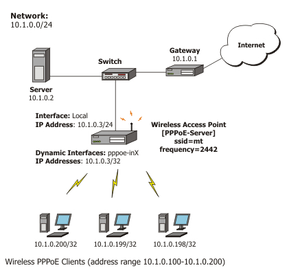
PPPoE in a multipoint wireless 802.11g network
In a wireless network, the PPPoE server may be attached to an Access Point (as well as to a regular station of wireless infrastructure). Either our RouterOS client or Windows PPPoE clients may connect to the Access Point for PPPoE authentication. Further, for RouterOS clients, the radio interface may be set to MTU 1600 so that the PPPoE interface may be set to MTU 1500. This optimizes the transmission of 1500 byte packets and avoids any problems associated with MTUs lower than 1500. It is not discussed here, how to change the MTU of the Windows wireless interface.
Let us consider the following setup where the MikroTik Wireless AP offers wireless clients transparent access to the local network with authentication:
First of all, the wireless interface should be configured:
[admin@PPPoE-Server] interface wireless> set 0 mode=ap-bridge \
   frequency=2442 band=2.4ghz-b/g ssid=mt disabled=no
[admin@PPPoE-Server] interface wireless> print
Flags: X - disabled, R - running
 0 X  name="wlan1" mtu=1500 mac-address=00:0C:42:18:5C:3D arp=enabled
      interface-type=Atheros AR5413 mode=ap-bridge ssid="mt" frequency=2442
      band=2.4ghz-b/g scan-list=default antenna-mode=ant-a wds-mode=disabled
      wds-default-bridge=none wds-ignore-ssid=no default-authentication=yes
      default-forwarding=yes default-ap-tx-limit=0 default-client-tx-limit=0
      hide-ssid=no security-profile=default compression=no
[admin@PPPoE-Server] interface wireless>
Now, configure the Ethernet interface, add the IP address and set the default route:
[admin@PPPoE-Server] ip address> add address=10.1.0.3/24 interface=Local
[admin@PPPoE-Server] ip address> print
Flags: X - disabled, I - invalid, D - dynamic
 #   ADDRESS            NETWORK         BROADCAST       INTERFACE
 0   10.1.0.3/24        10.1.0.0        10.1.0.255      Local
[admin@PPPoE-Server] ip address> /ip route
[admin@PPPoE-Server] ip route> add gateway=10.1.0.1
[admin@PPPoE-Server] ip route> print
Flags: X - disabled, A - active, D - dynamic,
C - connect, S - static, r - rip, b - bgp, o - ospf, m - mme,
B - blackhole, U - unreachable, P - prohibit
 #      DST-ADDRESS        PREF-SRC        G GATEWAY         DISTANCE INTER...
 0 ADC  10.1.0.0/24        10.1.0.3                          0        Local
 1 A S  0.0.0.0/0                          r 10.1.0.1        1        Local
[admin@PPPoE-Server] ip route> /interface ethernet
[admin@PPPoE-Server] interface ethernet> set Local arp=proxy-arp
[admin@PPPoE-Server] interface ethernet> print
Flags: X - disabled, R - running
 #    NAME                                   MTU   MAC-ADDRESS       ARP
 0  R Local                                  1500  00:0C:42:03:25:53 proxy-arp
[admin@PPPoE-Server] interface ethernet>
We should add PPPoE server to the wireless interface:
[admin@PPPoE-Server] interface pppoe-server server> add interface=wlan1 \
   service-name=mt one-session-per-host=yes disabled=no
[admin@PPPoE-Server] interface pppoe-server server> print
Flags: X - disabled
 0   service-name="mt" interface=wlan1 max-mtu=1480 max-mru=1480 mrru=disabled
     authentication=pap,chap,mschap1,mschap2 keepalive-timeout=10
     one-session-per-host=yes max-sessions=0 default-profile=default
[admin@PPPoE-Server] interface pppoe-server server>
Finally, we can set up PPPoE clients:
[admin@PPPoE-Server] ip pool> add name=pppoe ranges=10.1.0.100-10.1.0.200
[admin@PPPoE-Server] ip pool> print
 # NAME                                         RANGES
 0 pppoe                                        10.1.0.100-10.1.0.200
[admin@PPPoE-Server] ip pool> /ppp profile
[admin@PPPoE-Server] ppp profile> set default use-encryption=yes \
   local-address=10.1.0.3 remote-address=pppoe
[admin@PPPoE-Server] ppp profile> print
Flags: * - default
 0 * name="default" local-address=10.1.0.3 remote-address=pppoe
     use-compression=no use-vj-compression=no use-encryption=yes only-one=no
     change-tcp-mss=yes

 1 * name="default-encryption" use-compression=default
     use-vj-compression=default use-encryption=yes only-one=default
     change-tcp-mss=default
[admin@PPPoE-Server] ppp profile> .. secret
[admin@PPPoE-Server] ppp secret> add name=w password=wkst service=pppoe
[admin@PPPoE-Server] ppp secret> add name=l password=ltp service=pppoe
[admin@PPPoE-Server] ppp secret> print
Flags: X - disabled
 #   NAME        SERVICE CALLER-ID PASSWORD  PROFILE            REMOTE-ADDRESS
 0   w           pppoe             wkst      default            0.0.0.0
 1   l           pppoe             ltp       default            0.0.0.0
[admin@PPPoE-Server] ppp secret>
We have now completed the configuration and added two users: w and l who are able to connect to Internet, using PPPoE client software.
Note that Windows XP built-in client supports encryption, but RASPPPOE does not. So, if it is planned to support Windows clients older than Windows XP, it is recommended not to require encryption. In either case, the server is able to support clients that cannot encrypt the data.
FAQ
- What are those numbers in PPPoE client disconnect logs?
Numbers in log message contain following information: Uptime Bytes-In Bytes-Out Packets-In Packets-Out
- I can connect to my PPPoE server. I can even ping through it, but I still cannot open web pages
Make sure that you have specified a valid DNS server in the router (in /ip dns or in /ppp profile the dns-server parameter).
- The PPPoE server shows more than one active user entry for one client, when the clients disconnect, they are still shown and active
Set the keepalive-timeout parameter (in the PPPoE server configuration) to 10 if you want clients to be considered logged off if they do not respond for 10 seconds.
Note that if the keepalive-timeout parameter is set to 0 and the only-one parameter (in PPP profile settings) is set to ‘yes’ then the clients may be able to connect only the once. To resolve this problem one-session-per-host parameter in PPPoE server configuration should be set to ‘yes’
- My Windows XP client cannot connect to the PPPoE server
You have to specify the «Service Name» in the properties of the XP PPPoE client. If the service name is not set, or it does not match the service name of the MikroTik PPPoE server, you get the «line is busy» errors, or the system shows «verifying password — unknown error»
- I want to have logs for PPPoE connection establishment
Configure the logging feature under the /system logging facility and enable the PPP type logs. Read more >>
[ Top | Back to Content ]
PPPoE MTU is a buzz word that many people ask about even if they don’t have anything to do with network engineering. Just being a broadband subscriber with a PPPoE circuit is enough to get introduced to the concept.
In this post I will be explaining how PPPoE MTU is calculated and what is the default value. Therefore I would expect the reader to be familiar with what MTU is and with What PPPoE is.
PPPoE MTU:
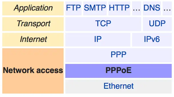
PPPoE MTU defines the maximum number of bytes that a PPPoE payload can have. This typically starts from IP layer in most cases. Below is what a typical PPPoE packet look like in terms of headers. Ethernet, then PPPoE then PPP followed by IP or IPv6 payload.
PPPoE MTU calculation = Interface MTU — Ethernet header (14 bytes) — PPPoE (6 bytes) — PPP (2 bytes)
The only variable in the above calculation is going to be the interface MTU setting, which defaults to 1514 as per the outputs below on a Juniper MX box with a GE interface.
This would give us the famous default value of 1492 bytes on most of standard equipment in the market. The value can be manipulated through configuration but it has to be manipulated over the complete path from the CPE to the BNG to avoid problems.
triton@neptune>show interfaces ge-4/1/8
Physical interface: ge-4/1/8, Enabled, Physical link is Down
Interface index: 182, SNMP ifIndex: 693
Link-level type: Ethernet, MTU: 1514, Speed: 1000mbps, BPDU Error: None,
Device flags   : Present Running Down

---- output ommitted ----
You can use this MTU (header overhead) calculator to calculate the PPPoE MTU or any other value based on specific setup requirements. Give it a try.
