
Купить FS коммутаторы для предприятий
Агрегация каналов-это подход к объединению нескольких отдельных каналов (Ethernet) в один логический канал. Вместе с ним часто появляются два термина, то есть LAG и LACP. Они вас смутили? Давайте теперь немного подробнее рассмотрим эти термины.
Не стесняйтесь забегать вперед, если вы уже позаботились о некоторых деталях.
1. Что такое LAG и как оно работает?
2. Что такое LACP и как он работает?
3. LAG vs LACP: в чем разница?
4.Можно ли включить агрегирование каналов?
5. Как настроить коммутатор агрегации каналов?
6. Сетевые коммутаторы, поддерживающие LAG
Что такое LAG и как это работает?
LAG (Link Aggregation Group) — это реальный метод или пример для агрегации каналов. Группа агрегации каналов формируется, когда мы подключаем несколько портов параллельно между двумя коммутаторами и настраиваем их как LAG. LAG создает несколько каналов между двумя коммутаторами, что увеличивает пропускную способность.
Кроме того, он обеспечивает резервирование на уровне канала при отказе сети и балансировке нагрузки трафика. Даже если одна связь выйдет из строя, остальные связи между двумя коммутаторами все равно будут работать. Они также принимают на себя тот трафик, который должен проходить через вышедшего из строя, поэтому пакет данных не будет потерян.
Что такое LACP (протокол управления агрегацией каналов) и как он работает?
LACP — это подкомпонент стандарта IEEE 802.3ad (Link Aggregation).Стандарт предписывает, что LACP может быть методом объединения нескольких физических каналов между сетевыми устройствами в один логический канал.
В результате, каналы, поддерживающие протокол LACP, могут увеличить логическую полосу пропускания и надежность сети без изменения какой-либо сетевой инфраструктуры.
Более того, даже если одна ссылка выходит из строя, в режиме LACP другие доступные члены ссылки в той же группе LACP будут балансировать нагрузку.

В момент, когда LACP включен между двумя коммутаторами, они будут отправлять LACPDU (блоки данных LACP) друг другу. После получения друг от друга LACPDU два коммутатора будут определять, у какой стороны системный приоритет выше.
Затем они будут вести переговоры друг с другом, чтобы выбрать того, кто выше, чтобы быть Актером, а тот, кто ниже, — Партнером. Если два коммутатора имеют одинаковый системный приоритет, коммутатор с меньшим значением MAC-адреса будет Актером.

После выбора Субъекта два коммутатора будут выбирать активные порты на основе приоритетов портов порта Субъекта. Однако, если порты Субъекта имеют одинаковые приоритеты, порты с меньшими номерами портов будут выбраны в качестве активных портов.
После выбора соответствующих портов двух коммутаторов устанавливается порт-канал (группа LACP). Тогда активные ссылки загрузят данные баланса для связи.
LAG vs LACP: в чем разница?
LAG (link aggregation group) относится к исходной технологии для реализации объединения каналов и балансировки нагрузки без участия какого-либо протокола. Он также называется ручным режимом из-за его рабочего процесса — пользователям необходимо вручную создать порт-канал и добавить интерфейсы-элементы к этому порту-каналу.
После того, как каналы агрегации установлены, все эти ссылки становятся активными ссылками для пересылки пакетов данных. Если одна активная ссылка не работает, остальные оставшиеся активные ссылки будут балансировать нагрузку на трафик. Однако этот режим может обнаруживать только разъединения входящих в него каналов, но не может обнаруживать другие сбои, такие как сбои канального уровня и неправильные соединения каналов.
LACP — это протокол для автоматической настройки и поддержки LAG. В режиме LACP порт-канал создается на основе LACP. LACP предоставляет стандартный механизм согласования для коммутационного устройства, так что коммутационное устройство может автоматически формировать и запускать агрегированный канал в соответствии с его конфигурацией. После того, как агрегированный канал сформирован, LACP отвечает за поддержание статуса канала.
Когда условие агрегирования ссылок изменяется, LACP корректирует или удаляет агрегированный канал. Если одна активная ссылка выходит из строя, система выбирает ссылку среди резервных ссылок в качестве активной ссылки. Таким образом, количество ссылок, участвующих в пересылке данных, остается неизменным. Кроме того, этот режим не только обнаруживает разъединения своих звеньев, но и другие сбои, такие как сбои канального уровня и неправильные соединения каналов.
Должен ли я включать агрегацию каналов?
Если у вас есть коммутатор с большим количеством портов Gigabit Ethernet, вы можете подключить их все к другому устройству, у которого также есть несколько портов, и сбалансировать трафик между этими каналами для повышения производительности.
Другой важной причиной использования агрегации каналов является обеспечение быстрого и прозрачного восстановления в случае отказа одного из отдельных каналов.
Если вы очень заботитесь о надежности и доступности сети, было бы лучше включить агрегацию каналов на ваших устройствах.
Как настроить коммутатор агрегации каналов?
Коммутатор агрегации каналов или коммутатор LACP, см. Установку или настройку коммутатора для достижения технологии агрегации каналов. Коммутатор агрегации каналов может быть любым коммутатором, например Gigabit Ethernet коммутатор или 10 Gigabit коммутатор, который поддерживает LACP. Как правило, существует шесть шагов для настройки коммутаторов агрегации каналов:
Шаг 1. Добавьте интерфейсы участников в группу каналов.
Шаг 2: Установите приоритет системы LACP и определите Субъекта, чтобы Партнер выбирал активные интерфейсы на основе приоритета интерфейса Субъекта.
Шаг 3: Установите верхний порог количества активных интерфейсов для повышения надежности. (Этот шаг необязательно применяется в командах динамической конфигурации CLI.)
Шаг 4: Установите приоритеты интерфейса LACP и определите активные интерфейсы, чтобы интерфейсы с более высоким приоритетом выбирались в качестве активных интерфейсов. (Этот шаг необязательно применяется в командах динамической конфигурации CLI.)
Шаг 5: Создайте сети VLAN и добавьте интерфейсы к этим VLAN. (Этот шаг необязательно применяется в командах динамической конфигурации CLI.)
Шаг 6: Проверьте конфигурацию LACP.
Коммутаторы поддерживающие LAG
Если вы ищете хорошие сетевые коммутаторы, поддерживающие LACP, вот три самых продаваемых коммутатора от FS, глобальной высокотехнологичной компании, предоставляющей решения и услуги для высокоскоростных сетей связи.
| S3900-24T4S | S5850-48S6Q | S5860-20SQ | |
|---|---|---|---|
| Уровень управления | Layer 2+ | Layer 3 | Layer 3 |
| Комбинация портов | 24 x 1G, 4 x 10G SFP+ | 48 x 10G SFP+, 6 x 40G QSFP+ | 20 x 10G SFP+, 4 x 25G SFP28, 2 x 40G QSFP+ |
| Ключевая особенность | VLAN, QoS, IGMP Snooping, Link Aggregation, IPv6,L3 статическая маршрутизация | VLAN, QoS, IGMP Snooping, Link Aggregation, статическая маршрутизация, RIP, OSPF, IPv6 поддержка, BGP/ISIS, MLAG | QoS, IGMP Snooping, Link Aggregation, IPv6, L3 статическая маршрутизация, RIP, OSPF, BGP/ISIS, стекируемый |
| Применения | SMB(<300 пользователей) | Предприятие (300-2500 пользователей) | Среднее & крупное предприятие (>2500 пользователей) |
Заключение
Вы получили представление об агрегирования каналов, LAG и LACP? Сможете ли вы использовать их с пользой и найти сетевой коммутатор, который вам подойдет? Агрегация каналов — это способ объединения нескольких отдельных (Ethernet) каналов, чтобы они могли работать как единое логическое соединение. Группа портов, объединенных вместе, называется группой агрегации каналов или LAG. Протокол активного мониторинга, который позволяет устройствам включать или удалять отдельные ссылки из LAG, называется протоколом управления агрегацией каналов (LACP).
LAG — link Aggregation
Определение/Назначение
Технология предназначенная, для агрегации каналов, т.е другими словами объединение нескольких физических портов в один логический.
Существует своя реализация LAG на оборудовании Nexus — VPC (Virtual Port Channel), про ее работу постараюсь написать отдельную статью, т.к. это достаточно большая и отдельная тема…
Descrambler:
Общий принцип работы:
Технология LAG может работать в 2-х режимах:
- Static — статический режим работы, это когда между двумя сторонами линка, объедененного а LAG нет никакой сигнализации о доступности второй стороны. Статический режим, п.э. имеет большой неостаток в этой связи, т.е. он не видит ошибки или какую либо проблему на канале, а включает линк в LAG и отключает линк из LAG на основании его физической доступности, т.е. если линк в «Up-е», то он всегда будет в LAG-e, если линк в «Down-е», то только это будет причиной исключения его из LAG-а. Соответственно, если с одной стороны порт является участником LAG-a, а с другой нет не будет служить основанием для исключения его с другой стороны LAG-a, если там он прописан как участник LAG-а. Соответственно такое поведение ведет к блекхолингу трафика, т.е. одна сторона думает, что все «ок»» и отправляет кадры в порт, который по сути может быть не настроен с другой стороны. Чтобы избежать подобных проблем внутри LAG-a используется протоколы сигнализации состояния канала LACP/PAgP.
PAgP — проприетарный протокол cisco, по сути на данный момент практически нигде не используется, п.э. про него говорить не буду…
- LACP — Link Aggregation Control Protocol. А во LACP «король» LAG-a…
Попробую рассказать про него на основе моей очень простой лабы:

Интерфейсы, участвующие в LAG, ну и соответственно в LACP тоже:
Sw1:
 - G0/1 - mac-address 5000.0003.0001
 - G0/2 - mac address 5000.0003.0002
Sw2:
 - G0/1 - mac-address 5000.0005.0001
 - G0/2 - mac-address 5000.0005.0002
Во-первых структура самого протокола весьма «ветвистая»

Для понимания работы достаточно понять общий принцип:
-
При установлении соединения протокол LACP использует в качестве DST mac-address 01:80:c2:00:00:02, а в качестве SRC mac-address указывает («виртуальный») наименьший из mac адресов своих интерфейсов, в моем случае это со стороны Sw1 5000.0003.0001 и соответственно со стороны Sw2 5000.0005.0001.
-
Наиболее значащими полями являтся «Actor State» — «собственное» состояние LACP и «Partner State» — состояние LACP партнера (что собственно следует из название поля).
-
Соединенные между собой порты работающие по LACP обмениваются информационными сообщениями LACP. В нормальном состоянии поля «Actor State» и «Partner State» имеют значение 0x3d

При этом можно посмотреть состояние портчана на обоих соседях


- При потери связности с партнером LACP проходит стадии


После этого такой линк исключается из LAG-a:


При необходимости можно подобрать более оптимальную балансировку из вариантов:
Sw1(config)#port-channel load-balance ?
  dst-ip       Dst IP Addr
  dst-mac      Dst Mac Addr
  src-dst-ip   Src XOR Dst IP Addr
  src-dst-mac  Src XOR Dst Mac Addr
  src-ip       Src IP Addr
  src-mac      Src Mac Addr
Посмотреть текущий тип балансировки:
Sw1#sh etherchannel load-balance
EtherChannel Load-Balancing Configuration:
        "src-dst-ip"

EtherChannel Load-Balancing Addresses Used Per-Protocol:
Non-IP: Source XOR Destination MAC address
  IPv4: Source XOR Destination IP address
  IPv6: Source XOR Destination IP address
Литература
- 1. Агрегирование каналов
- 2. Протокол агрегирования каналов: Etherchannel
Пример дампа lacp в wireshark можно посмотреть здесь
Последнее обновление: 2022-06-10
«IEEE 802.3ad» redirects here. Not to be confused with IEEE 802.1ad.

In computer networking, link aggregation is the combining (aggregating) of multiple network connections in parallel by any of several methods. Link aggregation increases total throughput beyond what a single connection could sustain, and provides redundancy where all but one of the physical links may fail without losing connectivity. A link aggregation group (LAG) is the combined collection of physical ports.
Other umbrella terms used to describe the concept include trunking,[1] bundling,[2] bonding,[1] channeling[3] or teaming.
Implementation may follow vendor-independent standards such as Link Aggregation Control Protocol (LACP) for Ethernet, defined in IEEE 802.1AX or the previous IEEE 802.3ad, but also proprietary protocols.
Motivation[edit]
Link aggregation increases the bandwidth and resilience of Ethernet connections.
Bandwidth requirements do not scale linearly. Ethernet bandwidths historically have increased tenfold each generation: 10 megabit/s, 100 Mbit/s, 1000 Mbit/s, 10,000 Mbit/s. If one started to bump into bandwidth ceilings, then the only option was to move to the next generation, which could be cost prohibitive. An alternative solution, introduced by many of the network manufacturers in the early 1990s, is to use link aggregation to combine two physical Ethernet links into one logical link. Most of these early solutions required manual configuration and identical equipment on both sides of the connection.[4]
There are three single points of failure inherent to a typical port-cable-port connection, in either a computer-to-switch or a switch-to-switch configuration: the cable itself or either of the ports the cable is plugged into can fail. Multiple logical connections can be made, but many of the higher level protocols were not designed to fail over completely seamlessly. Combining multiple physical connections into one logical connection using link aggregation provides more resilient communications.
Architecture[edit]
Network architects can implement aggregation at any of the lowest three layers of the OSI model. Examples of aggregation at layer 1 (physical layer) include power line (e.g. IEEE 1901) and wireless (e.g. IEEE 802.11) network devices that combine multiple frequency bands. OSI layer 2 (data link layer, e.g. Ethernet frame in LANs or multi-link PPP in WANs, Ethernet MAC address) aggregation typically occurs across switch ports, which can be either physical ports or virtual ones managed by an operating system. Aggregation at layer 3 (network layer) in the OSI model can use round-robin scheduling, hash values computed from fields in the packet header, or a combination of these two methods.
Regardless of the layer on which aggregation occurs, it is possible to balance the network load across all links. However, in order to avoid out-of-order delivery, not all implementations take advantage of this. Most methods provide failover as well.
Combining can either occur such that multiple interfaces share one logical address (i.e. IP) or one physical address (i.e. MAC address), or it allows each interface to have its own address. The former requires that both ends of a link use the same aggregation method, but has performance advantages over the latter.
Channel bonding is differentiated from load balancing in that load balancing divides traffic between network interfaces on per network socket (layer 4) basis, while channel bonding implies a division of traffic between physical interfaces at a lower level, either per packet (layer 3) or a data link (layer 2) basis.[citation needed]
IEEE link aggregation[edit]
Standardization process[edit]
By the mid-1990s, most network switch manufacturers had included aggregation capability as a proprietary extension to increase bandwidth between their switches. Each manufacturer developed its own method, which led to compatibility problems. The IEEE 802.3 working group took up a study group to create an interoperable link layer standard (i.e. encompassing the physical and data-link layers both) in a November 1997 meeting.[4] The group quickly agreed to include an automatic configuration feature which would add in redundancy as well. This became known as Link Aggregation Control Protocol (LACP).
802.3ad[edit]
As of 2000, most gigabit channel-bonding schemes used the IEEE standard of link aggregation which was formerly clause 43 of the IEEE 802.3 standard added in March 2000 by the IEEE 802.3ad task force.[5] Nearly every network equipment manufacturer quickly adopted this joint standard over their proprietary standards.
802.1AX[edit]
The 802.3 maintenance task force report for the 9th revision project in November 2006 noted that certain 802.1 layers (such as 802.1X security) were positioned in the protocol stack below link aggregation which was defined as an 802.3 sublayer.[6] To resolve this discrepancy, the 802.3ax (802.1AX) task force was formed,[7] resulting in the formal transfer of the protocol to the 802.1 group with the publication of IEEE 802.1AX-2008 on 3 November 2008.[8]
Link Aggregation Control Protocol[edit]
Within the IEEE Ethernet standards, the Link Aggregation Control Protocol (LACP) provides a method to control the bundling of several physical links together to form a single logical link. LACP allows a network device to negotiate an automatic bundling of links by sending LACP packets to their peer, a directly connected device that also implements LACP.
LACP Features and practical examples
- Maximum number of bundled ports allowed in the port channel: Valid values are usually from 1 to 8.
- LACP packets are sent with multicast group MAC address 01:80:C2:00:00:02
- During LACP detection period
- LACP packets are transmitted every second
- Keep-alive mechanism for link member: (default: slow = 30s, fast=1s)[specify]
- Selectable load-balancing mode is available in some implementations[9]
- LACP mode :
- Active: Enables LACP unconditionally.
- Passive: Enables LACP only when an LACP device is detected. (This is the default state)[specify]
Advantages over static configuration[edit]
- Failover occurs automatically: When a link has an intermediate failure, for example in a media converter between the devices, a peer system may not perceive any connectivity problems. With static link aggregation, the peer would continue sending traffic down the link causing the connection to fail.
- Dynamic configuration: The device can confirm that the configuration at the other end can handle link aggregation. With static link aggregation, a cabling or configuration mistake could go undetected and cause undesirable network behavior.[10]
Practical notes[edit]
LACP works by sending frames (LACPDUs) down all links that have the protocol enabled. If it finds a device on the other end of a link that also has LACP enabled, that device will independently send frames along the same links in the opposite direction enabling the two units to detect multiple links between themselves and then combine them into a single logical link. LACP can be configured in one of two modes: active or passive. In active mode, LACPDUs are sent 1 per second along the configured links. In passive mode, LACPDUs are not sent until one is received from the other side, a speak-when-spoken-to protocol.
Proprietary link aggregation[edit]
In addition to the IEEE link aggregation substandards, there are a number of proprietary aggregation schemes including Cisco’s EtherChannel and Port Aggregation Protocol, Juniper’s Aggregated Ethernet, AVAYA’s Multi-Link Trunking, Split Multi-Link Trunking, Routed Split Multi-Link Trunking and Distributed Split Multi-Link Trunking, ZTE’s Smartgroup, Huawei’s Eth-Trunk, and Connectify’s Speedify.[11] Most high-end network devices support some form of link aggregation. Software-based implementations – such as the *BSD lagg package, Linux bonding driver, Solaris dladm aggr, etc. – exist for many operating systems.
Linux drivers[edit]
The Linux bonding driver[12] provides a method for aggregating multiple network interface controllers (NICs) into a single logical bonded interface of two or more so-called (NIC) slaves. The majority of modern Linux distributions come with a Linux kernel which has the Linux bonding driver integrated as a loadable kernel module and the ifenslave (if = [network] interface) user-level control program pre-installed. Donald Becker programmed the original Linux bonding driver. It came into use with the Beowulf cluster patches for the Linux kernel 2.0.
Modes for the Linux bonding driver[12] (network interface aggregation modes) are supplied as parameters to the kernel bonding module at load time. They may be given as command-line
arguments to the insmod or modprobe commands, but are usually specified in a Linux distribution-specific configuration file. The behavior of the single logical bonded interface depends upon its specified bonding driver mode. The default parameter is balance-rr.
- Round-robin (balance-rr)
- Transmit alternate network packets in sequential order from the first available NIC slave through the last. This mode provides load balancing and fault tolerance.[13] This mode can cause congestion control issues due to the packet reordering it can introduce.[14]
- Active-backup (active-backup)
- Only one NIC slave in the bond is active. A different slave becomes active if, and only if, the active slave fails. The single logical bonded interface’s MAC address is externally visible on only one NIC (port) to simplify forwarding in the network switch. This mode provides fault tolerance.
- XOR (balance-xor)
- Transmit network packets based on a hash of the packet’s source and destination. The default algorithm only considers MAC addresses (layer2). Newer versions allow selection of additional policies based on IP addresses (layer2+3) and TCP/UDP port numbers (layer3+4). This selects the same NIC slave for each destination MAC address, IP address, or IP address and port combination, respectively. Single connections will have guaranteed in order packet delivery and will transmit at the speed of a single NIC.[15] This mode provides load balancing and fault tolerance.
- Broadcast (broadcast)
- Transmit network packets on all slave network interfaces. This mode provides fault tolerance.
- IEEE 802.3ad Dynamic link aggregation (802.3ad, LACP)
- Creates aggregation groups that share the same speed and duplex settings. Utilizes all slave network interfaces in the active aggregator group according to the 802.3ad specification. This mode is similar to the XOR mode above and supports the same balancing policies. The link is set up dynamically between two LACP-supporting peers.
- Adaptive transmit load balancing (balance-tlb)
- Linux bonding driver mode that does not require any special network-switch support. The outgoing network packet traffic is distributed according to the current load (computed relative to the speed) on each network interface slave. Incoming traffic is received by one currently designated slave network interface. If this receiving slave fails, another slave takes over the MAC address of the failed receiving slave.
- Adaptive load balancing (balance-alb)
- includes balance-tlb plus receive load balancing (rlb) for IPv4 traffic and does not require any special network switch support. The receive load balancing is achieved by ARP negotiation. The bonding driver intercepts the ARP Replies sent by the local system on their way out and overwrites the source hardware address with the unique hardware address of one of the NIC slaves in the single logical bonded interface such that different network-peers use different MAC addresses for their network packet traffic.
The Linux Team driver[16] provides an alternative to bonding driver. The main difference is that Team driver kernel part contains only essential code and the rest of the code (link validation, LACP implementation, decision making, etc.) is run in userspace as a part of teamd daemon.
Usage[edit]
Network backbone[edit]
Link aggregation offers an inexpensive way to set up a high-capacity backbone network that transfers multiple times more data than any single port or device can deliver. Link aggregation also allows the network’s backbone speed to grow incrementally as demand on the network increases, without having to replace everything and deploy new hardware.
Most backbone installations install more cabling or fiber optic pairs than is initially necessary. This is done because labor costs are higher than the cost of the cable, and running extra cable reduces future labor costs if networking needs change. Link aggregation can allow the use of these extra cables to increase backbone speeds for little or no extra cost if ports are available.
Order of frames[edit]
When balancing traffic, network administrators often wish to avoid reordering Ethernet frames. For example, TCP suffers additional overhead when dealing with out-of-order packets. This goal is approximated by sending all frames associated with a particular session across the same link. Common implementations use L2 or L3 hashes (i.e. based on the MAC or the IP addresses), ensuring that the same flow is always sent via the same physical link.[17][18][19]
However, this may not provide even distribution across the links in the trunk when only a single or very few pairs of hosts communicate with each other, i.e. when the hashes provide too little variation. It effectively limits the client bandwidth in aggregate.[18] In the extreme, one link is fully loaded while the others are completely idle and aggregate bandwidth is limited to this single member’s maximum bandwidth. For this reason, an even load balancing and full utilization of all trunked links is almost never reached in real-life implementations.
Use on network interface cards[edit]
NICs trunked together can also provide network links beyond the throughput of any one single NIC. For example, this allows a central file server to establish an aggregate 2-gigabit connection using two 1-gigabit NICs teamed together. Note the data signaling rate will still be 1 Gbit/s, which can be misleading depending on methodologies used to test throughput after link aggregation is employed.
Microsoft Windows[edit]
Microsoft Windows Server 2012 supports link aggregation natively. Previous Windows Server versions relied on manufacturer support of the feature within their device driver software. Intel, for example, released Advanced Networking Services (ANS) to bond Intel Fast Ethernet and Gigabit cards.[20]
Nvidia supports teaming with their Nvidia Network Access Manager/Firewall Tool. HP has a teaming tool for HP-branded NICs which supports several modes of link aggregation including 802.3ad with LACP. In addition, there is a basic layer-3 aggregation[21] that allows servers with multiple IP interfaces on the same network to perform load balancing, and for home users with more than one internet connection, to increase connection speed by sharing the load on all interfaces.[22]
Broadcom offers advanced functions via Broadcom Advanced Control Suite (BACS), via which the teaming functionality of BASP (Broadcom Advanced Server Program) is available, offering 802.3ad static LAGs, LACP, and «smart teaming» which doesn’t require any configuration on the switches to work. It is possible to configure teaming with BACS with a mix of NICs from different vendors as long as at least one of them is from Broadcom and the other NICs have the required capabilities to support teaming.[23]
Linux and UNIX[edit]
Linux, FreeBSD, NetBSD, OpenBSD, macOS, OpenSolaris and commercial Unix distributions such as AIX implement Ethernet bonding at a higher level and, as long as the NIC is supported by the kernel, can deal with NICs from different manufacturers or using different drivers.[12]
Virtualization platforms[edit]
Citrix XenServer and VMware ESX have native support for link aggregation. XenServer offers both static LAGs as well as LACP. vSphere 5.1 (ESXi) supports both static LAGs and LACP natively with their virtual distributed switch.[24]
Microsoft’s Hyper-V does not offer link aggregation support from the hypervisor level, but the above-mentioned methods for teaming under Windows apply to Hyper-V.
Limitations[edit]
Single switch[edit]
With the modes balance-rr, balance-xor, broadcast and 802.3ad, all physical ports in the link aggregation group must reside on the same logical switch, which, in most common scenarios, will leave a single point of failure when the physical switch to which all links are connected goes offline. The modes active-backup, balance-tlb, and balance-alb can also be set up with two or more switches. But after failover (like all other modes), in some cases, active sessions may fail (due to ARP problems) and have to be restarted.
However, almost all vendors have proprietary extensions that resolve some of this issue: they aggregate multiple physical switches into one logical switch. Nortel’s split multi-link trunking (SMLT) protocol allows multiple Ethernet links to be split across multiple switches in a stack, preventing any single point of failure and additionally allowing all switches to be load balanced across multiple aggregation switches from the single access stack. These devices synchronize state across an Inter-Switch Trunk (IST) such that they appear to the connecting (access) device to be a single device (switch block) and prevent any packet duplication. SMLT provides enhanced resiliency with sub-second failover and sub-second recovery for all speed trunks while operating transparently to end-devices.
Multi-chassis link aggregation group provides similar features in a vendor-nonspecific manner. To the connected device, the connection appears as a normal link aggregated trunk. The coordination between the multiple sources involved is handled in a vendor-specific manner.
Same link speed[edit]
In most implementations, all the ports used in an aggregation consist of the same physical type, such as all copper ports (10/100/1000BASE‑T), all multi-mode fiber ports, or all single-mode fiber ports. However, all the IEEE standard requires is that each link be full duplex and all of them have an identical speed (10, 100, 1,000 or 10,000 Mbit/s).
Many switches are PHY independent, meaning that a switch could have a mixture of copper, SX, LX, LX10 or other GBIC/SFP modular transceivers. While maintaining the same PHY is the usual approach, it is possible to aggregate a 1000BASE-SX fiber for one link and a 1000BASE-LX (longer, diverse path) for the second link. One path may have a longer propagation time but since most implementations keep a single traffic flow on the same physical link (using a hash of either MAC addresses, IP addresses, or IP/transport-layer port combinations as index) this doesn’t cause problematic out-of-order delivery.
Ethernet aggregation mismatch[edit]
Aggregation mismatch refers to not matching the aggregation type on both ends of the link. Some switches do not implement the 802.1AX standard but support static configuration of link aggregation. Therefore, link aggregation between similarly statically configured switches may work but will fail between a statically configured switch and a device that is configured for LACP.
Examples[edit]
Ethernet[edit]
On Ethernet interfaces, channel bonding requires assistance from both the Ethernet switch and the host computer’s operating system, which must stripe the delivery of frames across the network interfaces in the same manner that I/O is striped across disks in a RAID 0 array.[citation needed] For this reason, some discussions of channel bonding also refer to Redundant Array of Inexpensive Nodes (RAIN) or to redundant array of independent network interfaces.[25]
Modems[edit]
In analog modems, multiple dial-up links over POTS may be bonded. Throughput over such bonded connections can come closer to the aggregate bandwidth of the bonded links than can throughput under routing schemes which simply load-balance outgoing network connections over the links.
DSL[edit]
Similarly, multiple DSL lines can be bonded to give higher bandwidth; in the United Kingdom, ADSL is sometimes bonded to give for example 512 kbit/s upload bandwidth and 4 megabit/s download bandwidth, in areas that only have access to 2 megabit/s bandwidth.[citation needed]
DOCSIS[edit]
Under the DOCSIS 3.0 and 3.1 specifications for data over cable TV systems, multiple channels may be bonded. Under DOCSIS 3.0, up to 32 downstream and 8 upstream channels may be bonded.[26] These are typically 6 or 8 MHz wide. DOCSIS 3.1 defines more complicated arrangements involving aggregation at the level of subcarriers and larger notional channels.[27]
Wireless Broadband[edit]
Broadband bonding is a type of channel bonding that refers to aggregation of multiple channels at OSI layers at level four or above. Channels bonded can be wired links such as a T-1 or DSL line. Additionally, it is possible to bond multiple cellular links for an aggregated wireless bonded link.
Previous bonding methodologies resided at lower OSI layers, requiring coordination with telecommunications companies for implementation. Broadband bonding, because it is implemented at higher layers, can be done without this coordination.[28]
Commercial implementations of Broadband Channel Bonding include:
- Wistron AiEdge Corporation’s U-Bonding Technology [29]
- Mushroom Networks’ Broadband Bonding Service [30]
- Connectify’s Speedify fast bonding VPN — software app for multiple platforms: PC, Mac, iOS and Android [31]
- Peplink’s SpeedFusion Bonding Technology [32]
- Viprinet’s Multichannel VPN Bonding Technology [33]
- Elsight’s Multichannel Secure Data Link [34]
- Synopi’s Natiply Internet Bonding Technology [35]
- ComBOX Networks multi-wan bonding as a service [36]
Wi-Fi[edit]
- On 802.11 (Wi-Fi), channel bonding is used in Super G technology, referred to as 108Mbit/s. It bonds two channels of standard 802.11g, which has 54Mbit/s data signaling rate.
- On IEEE 802.11n, a mode with a channel width of 40 MHz is specified. This is not channel bonding, but a single channel with double the older 20 MHz channel width, thus using two adjacent 20 MHz bands. This allows direct doubling of the PHY data rate from a single 20 MHz channel, but the MAC and user-level throughput also depends on other factors so may not double.[citation needed]
See also[edit]
- FlexE
- Inverse multiplexer
- Spanning Tree Protocol
References[edit]
- ^ a b Guijarro, Manuel; Ruben Gaspar; et al. (2008). «Experience and Lessons learnt from running High Availability Databases on Network Attached Storage» (PDF). Journal of Physics: Conference Series. Conference Series. IOP Publishing. 119 (4): 042015. Bibcode:2008JPhCS.119d2015G. doi:10.1088/1742-6596/119/4/042015. Retrieved 2009-08-17.
Network bonding (also known as port trunking) consists of aggregating multiple network interfaces into a single logical bonded interface that correspond to a single IP address.
- ^ «IEEE 802.3ad Link Bundling». Cisco Systems. 2007-02-27. Archived from the original on 2012-04-19. Retrieved 2012-03-15.
- ^ «Cisco Nexus 5000 Series NX-OS Software Configuration Guide — Configuring Port Channels [Cisco Nexus 5000 Series Switches]». Cisco. Retrieved 2019-10-25.
- ^ a b «IEEE 802 Trunking Tutorial». 1997-11-11. Archived from the original on 2013-12-07. Retrieved 2013-08-13.
- ^ «IEEE 802.3ad Link Aggregation Task Force». www.ieee802.org. Archived from the original on 27 October 2017. Retrieved 9 May 2018.
- ^ Law, David (2006-11-13). «IEEE 802.3 Maintenance» (PDF). p. 9. Archived (PDF) from the original on 2008-10-07. Retrieved 2009-08-18.
Proposal to move Link Aggregation to IEEE 802.1 •It is an 802.3 sublayer but it has to go above IEEE Std 802.1x
- ^ «IEEE 802.3ax (IEEE P802.1AX) Link Aggregation Project Authorization Request (approved)» (PDF). 2007-03-22. p. 3. Archived from the original (PDF) on 2010-11-16. Retrieved 2018-01-10.
It has been concluded between 802.1 and 802.3 that future development of Link Aggregation would be more appropriate as an 802.1 standard
- ^ «IEEE SA — 802.1AX-2008 — IEEE Standard for Local and metropolitan area networks—Link Aggregation». Archived from the original on 2013-08-07. Retrieved 2013-08-13.
- ^ «What Is LACP?». Retrieved 5 March 2020.
- ^ «Link aggregation on Dell servers» (PDF). Archived from the original (PDF) on 13 March 2012.
- ^ «Connectify commercializes Speedify channel bonding service — FierceWireless». www.fiercewireless.com. Archived from the original on 28 June 2016. Retrieved 9 May 2018.
- ^ a b c The Linux Foundation: Bonding Archived 2010-12-28 at the Wayback Machine
- ^ «Understanding NIC Bonding with Linux». 2 December 2009.
- ^ «Linux Ethernet Bonding Driver HOWTO». Retrieved 2021-11-27.
- ^ https://www.kernel.org/doc/Documentation/networking/bonding.txt[bare URL plain text file]
- ^ «libteam by jpirko». www.libteam.org. Archived from the original on 14 September 2017. Retrieved 9 May 2018.
- ^ «IEEE 802.3ad Link Aggregation (LAG) what it is, and what it is not» (PDF). Archived (PDF) from the original on 2007-11-29. Retrieved 2007-05-14.[unreliable source?]
- ^ a b Mechanisms for Optimizing Link Aggregation Group (LAG) and Equal-Cost Multipath (ECMP) Component Link Utilization in Networks. doi:10.17487/RFC7424. RFC 7424.
- ^ «Outbound Traffic Distribution Across Trunked Links». Procurve 2910al Management and Configuration Guide. Hewlett Packard. February 2009.
- ^ Intel Advanced Networking Services Archived 2007-01-24 at the Wayback Machine
- ^ Archiveddocs. «RandomAdapter: Core Services». technet.microsoft.com. Archived from the original on 25 April 2016. Retrieved 9 May 2018.
- ^ «Norton Internet Security™ — PC Protection». www.pctools.com. Archived from the original on 1 April 2017. Retrieved 9 May 2018.
- ^ Broadcom Windows Management Applications Archived 2012-08-01 at the Wayback Machine, visited 8 July 2012
- ^ «What’s New in vSphere 5.1 networking» (PDF). June 2012. Archived from the original (PDF) on 2014-01-23.
- ^
Jielin Dong, ed. (2007). Network Dictionary. ITPro collection. Javvin Technologies Inc. p. 95. ISBN 9781602670006. Retrieved 2013-08-07.Channel bonding, sometimes also called redundant array of independent network interfaces (RAIN), is an arrangement in which two or more network interfaces on a host computer are combined for redundancy or increased throughput.
- ^ DOCSIS 3.0 Physical Interface Specification
- ^ DOCSIS 3.1 Physical Interface Specification
- ^ «Broadband bonding offers high-speed alternative». engineeringbook.net. Archived from the original on 7 July 2012. Retrieved 5 April 2013.
- ^ «Ubonding | Wistron». 17 November 2022.
- ^ Mushroom Networks’ Broadband Bonding Service
- ^ Connectify’s Speedify Service
- ^ Peplink’s SpeedFusion Bonding Technology
- ^ Viprinet’s Multichannel VPN Bonding Technology
- ^ Elsight Multichannel Secure Data Link
- ^ Synopi’s Natiply Internet Bonding Technology
- ^ comBOX multi-wan services Broadband bonding
- General
- «Chapter 5.4: Link Aggregation Control Protocol (LACP)». IEEE Std 802.1AX-2008 IEEE Standard for Local and Metropolitan Area Networks — Link Aggregation (PDF). IEEE Standards Association. 2008-11-03. p. 30. doi:10.1109/IEEESTD.2008.4668665. ISBN 978-0-7381-5794-8.
- Tech Tips — Bonding Modes
External links[edit]
- IEEE P802.3ad Link Aggregation Task Force
- Mikrotik link Aggregation / Bonding Guide
- Configuring a Shared Ethernet Adapter (SEA) — IBM
- Managing VLANs on mission-critical shared Ethernet adapters — IBM
- Network overview by Rami Rosen (section about bonding)
Сегодня поговорим о настройке LAG и VLAN на роутере Mikrotik RB4011. Для тех, кто хочет немного теории по этим двум технологиям, советую прочитать предыдущую статью – Настройка LAG и VLAN на коммутаторах Mikrotik CRS 100x & 200x
За основу возьмем ту же схему, только теперь настроим роутер RB4011.

Создаем bonding interface через раздел Interfaces -> Bonding
/interface bonding
add mode=balance-xor name="bonding CRS109" slaves="ether1 LINK_1 CRS109,ether2 LINK_2 CRS109" transmit-hash-policy=layer-2-and-3
т.к LAG со стороны CRS109 работает в режиме balance-xor, на роутере также выставляем balance-xor.
VLAN
В отличие от коммутаторов CRS100x & 200x, современные роутеры Mikrotik и коммутаторы CRS300x обрабатывают VLAN на бридже.
a) создаем бридж и включаем на нем vlan-filtering
/interface bridge
add admin-mac=11:22:33:44:55:66 auto-mac=no name=bridge vlan-filtering=yes
в вашем случае mac address бриджа будет другой.
б) Добавляем LAG в бридж
/interface bridge port
add bridge=bridge interface="bonding CRS109"
в) Создаем таблицу VLAN
/interface vlan
add interface=bridge name="vlan20" vlan-id=20
add interface=bridge name="vlan30" vlan-id=30
г) Описываем vlan на trunk интерфейсе
/interface bridge vlan
add bridge=bridge tagged="bridge,bonding CRS109" vlan-ids=20
add bridge=bridge tagged="bridge,bonding CRS109" vlan-ids=30
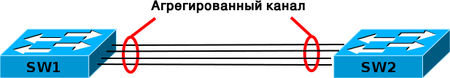
Агрегирование каналов — технология, которая позволяет объединить несколько физических каналов в один логический. Такое объединение позволяет увеличивать пропускную способность и надежность канала.
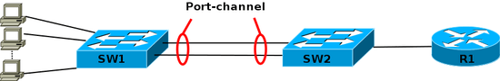
Агрегирование каналов может быть настроено между двумя коммутаторами, коммутатором и маршрутизатором, между коммутатором и хостом.
Для агрегирования каналов существуют другие названия:
- Port Trunking (в Cisco trunk’ом называется тегированный порт, поэтому с этим термином путаницы больше всего),
- EtherChannel (в Cisco так называется агрегирование каналов, это может относиться как к настройке статических агрегированных каналов, так и с использованием протоколов LACP или PAgP)
- И еще множество других: Ethernet trunk, NIC Teaming, Port Channel, Port Teaming, LAG (link aggregation), Link Bundling, Multi-Link Trunking (MLT), DMLT, SMLT, DSMLT, R-SMLT, NIC bonding, Network Fault Tolerance (NFT), Fast EtherChannel.
Общая информация об агрегировании каналов
Агрегирование каналов позволяет решить две задачи:
- повысить пропускную способность канала
- обеспечить резерв на случай выхода из строя одного из каналов
Большинство технологий по агрегированию позволяют объединять только параллельные каналы. То есть такие, которые начинаются на одном и том же устройстве и заканчиваются на другом.
Если рассматривать избыточные соединения между коммутаторами, то без использования специальных технологий для агрегирования каналов, передаваться данные будут только через один интерфейс, который не заблокирован STP. Такой вариант позволяет обеспечить резервирование каналов, но не дает возможности увеличить пропускную способность.

(Без использования STP такое избыточное соединение создаст петлю в сети.)
Технологии по агрегированию каналов позволяют использовать все интерфейсы одновременно. При этом устройства контролируют распространение широковещательных фреймов (а также multicast и unknown unicast), чтобы они не зацикливались. Для этого коммутатор, при получении широковещательного фрейма через обычный интерфейс, отправляет его в агрегированный канал только через один интерфейс. А при получении широковещательного фрейма из агрегированного канала, не отправляет его назад.
Хотя агрегирование каналов позволяет увеличить пропускную способность канала, не стоит рассчитывать на идеальную балансировку нагрузки между интерфейсами в агрегированном канале. Технологии по балансировке нагрузки в агрегированных каналах, как правило, ориентированы на балансировку по таким критериям: MAC-адресам, IP-адресам, портам отправителя или получателя (по одному критерию или их комбинации).
То есть, реальная загруженность конкретного интерфейса никак не учитывается. Поэтому один интерфейс может быть загружен больше, чем другие. Более того, при неправильном выборе метода балансировки (или если недоступны другие методы) или в некоторых топологиях, может сложиться ситуация, когда реально все данные будут передаваться, например, через один интерфейс.
Некоторые проприетарные разработки позволяют агрегировать каналы, которые соединяют разные устройства. Таким образом резервируется не только канал, но и само устройство. Такие технологии в общем, как правило, называются распределенным агрегированием каналов (у многих производителей есть своё название для этой технологии).
Агрегирование каналов в Cisco
Для агрегирования каналов в Cisco может быть использован один из трёх вариантов:
- LACP (Link Aggregation Control Protocol) стандартный протокол
- PAgP (Port Aggregation Protocol) проприетарный протокол Cisco
- Статическое агрегирование без использования протоколов
Так как LACP и PAgP решают одни и те же задачи (с небольшими отличиями по возможностям), то лучше использовать стандартный протокол. Фактически остается выбор между LACP и статическим агрегированием.
Статическое агрегирование:
- Преимущества:
- Не вносит дополнительную задержку при поднятии агрегированного канала или изменении его настроек
- Вариант, который рекомендует использовать Cisco
- Недостатки:
- Нет согласования настроек с удаленной стороной. Ошибки в настройке могут привести к образованию петель
Агрегирование с помощью LACP:
- Преимущества:
- Согласование настроек с удаленной стороной позволяет избежать ошибок и петель в сети.
- Поддержка standby-интерфейсов позволяет агрегировать до 16ти портов, 8 из которых будут активными, а остальные в режиме standby
- Недостатки:
- Вносит дополнительную задержку при поднятии агрегированного канала или изменении его настроек.
Терминология и настройка
При настройке агрегирования каналов на оборудовании Cisco используется несколько терминов:
- EtherChannel — технология агрегирования каналов. Термин, который использует Cisco для агрегирования каналов.
- port-channel — логический интерфейс, который объединяет физические интерфейсы.
- channel-group — команда, которая указывает какому логическому интерфейсу принадлежит физический интерфейс и какой режим используется для агрегирования.
Эти термины используются при настройке, в командах просмотра, независимо от того, какой вариант агрегирования используется (какой протокол, какого уровня EtherChannel).
На схеме, число после команды channel-group указывает какой номер будет у логического интерфейса Port-channel. Номера логических интерфейсов с двух сторон агрегированного канала не обязательно должны совпадать. Номера используются для того чтобы отличать разные группы портов в пределах одного коммутатора.
Общие правила настройки EtherChannel
LACP и PAgP группируют интерфейсы с одинаковыми:
- скоростью (speed),
- режимом дуплекса (duplex mode),
- native VLAN,
- диапазон разрешенных VLAN,
- trunking status,
- типом интерфейса.
Настройка EtherChannel:
- Так как для объединения в EtherChannel на интерфейсах должны совпадать многие настройки, проще объединять их, когда они настроены по умолчанию. А затем настраивать логический интерфейс.
- Перед объединением интерфейсов лучше отключить их. Это позволит избежать блокирования интерфейсов STP (или перевода их в состояние err-disable).
- Для того чтобы удалить настройки EtherChannel достаточно удалить логический интерфейс. Команды channel-group удалятся автоматически.
Создание EtherChannel для портов уровня 2 и портов уровня 3 отличается:
- Для интерфейсов 3го уровня вручную создается логический интерфейс командой interface port-channel
- Для интерфейсов 2го уровня логический интерфейс создается динамически
- Для обоих типов интерфейсов необходимо вручную назначать интерфейс в EtherChannel. Для этого используется команда channel-group в режиме настройки интерфейса. Эта команда связывает вместе физические и логические порты
После того как настроен EtherChannel:
- изменения, которые применяются к port-channel интерфейсу, применяются ко всем физическим портам, которые присвоены этому port-channel интерфейсу
- изменения, которые применяются к физическому порту влияют только на порт на котором были сделаны изменения
Синтаксис команды channel-group
Синтаксис команды channel-group:
sw(config-if)# channel-group <channel-group-number> mode <<auto [non-silent] |
desirable [non-silent] | on> | <active | passive>>
Параметры команды:
- active — Включить LACP,
- passive — Включить LACP только если придет сообщение LACP,
- desirable — Включить PAgP,
- auto — Включить PAgP только если придет сообщение PAgP,
- on — Включить только Etherchannel.
Комбинации режимов при которых поднимется EtherChannel:
| Режим PAgP | auto | desirable |
|---|---|---|
| auto | — | EtherChannel |
| desirable | EtherChannel | EtherChannel |
| Режим LACP | passive | active |
|---|---|---|
| passive | — | EtherChannel |
| active | EtherChannel | EtherChannel |
Интерфейсы в состоянии suspended
Если настройки физического интерфейса не совпадают с настройками агрегированного интерфейса, он переводится в состояние suspended. Это будет видно в нескольких командах.
Просмотр состояния интерфейсов:
sw1#sh int status

Port      Name               Status       Vlan       Duplex  Speed Type
...
Fa0/9                        notconnect   1            auto   auto 10/100BaseTX
Fa0/10                       notconnect   1            auto   auto 10/100BaseTX
Fa0/11                       connected    trunk      a-full  a-100 10/100BaseTX
Fa0/12                       connected    trunk      a-full  a-100 10/100BaseTX
Fa0/13                       suspended    1          a-full  a-100 10/100BaseTX
Fa0/14                       connected    trunk      a-full  a-100 10/100BaseTX
...
Po1                          connected    trunk      a-full  a-100
Просмотр информации о EtherChannel:
sw1#sh etherchannel summary
Flags: D - down        P - bundled in port-channel
       I - stand-alone s - suspended
       H - Hot-standby (LACP only)
       R - Layer3      S - Layer2
       U - in use      f - failed to allocate aggregator

       M - not in use, minimum links not met
       u - unsuitable for bundling
       w - waiting to be aggregated
       d - default port


Number of channel-groups in use: 1
Number of aggregators:           1

Group  Port-channel  Protocol    Ports
------+-------------+-----------+-----------------------------------------------
1      Po1(SU)         LACP      Fa0/11(P)   Fa0/12(P)   Fa0/13(s)
                                 Fa0/14(P)
Команды просмотра информации
sw# show etherchannel summary
sw1#sh etherchannel port-channel
Подробная информация:
sw1#sh etherchannel detail
Настройка EtherChannel 2го уровня
Настройка статического EtherChannel 2го уровня

Перед настройкой агрегирования лучше выключить физические интерфейсы. Достаточно отключить их с одной стороны (в примере на sw1), затем настроить агрегирование с двух сторон и включить интерфейсы.
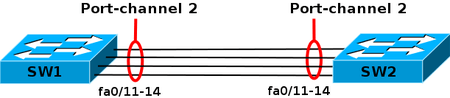
Настройка EtherChannel на sw1:
sw1(config)# interface range f0/11-14
sw1(config-if-range)# shutdown
sw1(config-if-range)# channel-group 3 mode on
Creating a port-channel interface Port-channel 3
Настройка EtherChannel на sw2:
sw2(config)# interface range f0/11-14
sw2(config-if-range)# channel-group 3 mode on
Creating a port-channel interface Port-channel 3
Включение физических интерфейсов на sw1:
sw1(config-if-range)# no sh
Просмотр информации
Суммарная информация о состоянии Etherchannel:
sw1# sh etherchannel summary
Flags:  D - down        P - bundled in port-channel
        I - stand-alone s - suspended
        H - Hot-standby (LACP only)
        R - Layer3      S - Layer2
        U - in use      f - failed to allocate aggregator

        M - not in use, minimum links not met
        u - unsuitable for bundling
        w - waiting to be aggregated
        d - default port


Number of channel-groups in use: 1
Number of aggregators:           1

Group  Port-channel  Protocol    Ports
------+-------------+-----------+-----------------------------------------------
3      Po3(SU)          -        Fa0/11(P)   Fa0/12(P)   Fa0/13(P)
                                 Fa0/14(P)
Информация о port-channel на sw1:
sw1# sh etherchannel port-channel
                Channel-group listing:
                ----------------------

Group: 3
----------
                Port-channels in the group:
                ---------------------------

Port-channel: Po3
------------

Age of the Port-channel   = 0d:00h:00m:51s
Logical slot/port   = 1/0          Number of ports = 4
GC                  = 0x00000000      HotStandBy port = null
Port state          = Port-channel Ag-Inuse
Protocol            =    -
Port security       = Disabled

Ports in the Port-channel:

Index   Load   Port     EC state        No of bits
------+------+------+------------------+-----------
  0     00     Fa0/11   On                 0
  0     00     Fa0/12   On                 0
  0     00     Fa0/13   On                 0
  0     00     Fa0/14   On                 0

Time since last port bundled:    0d:00h:00m:44s    Fa0/14
Настройка EtherChannel 2го уровня с помощью LACP
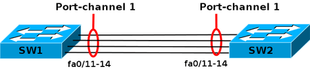
Перед настройкой агрегирования лучше выключить физические интерфейсы. Достаточно отключить их с одной стороны (в примере на sw1), затем настроить агрегирование с двух сторон и включить интерфейсы.
Настройка EtherChannel на sw1:
sw1(config)# interface range f0/11-14
sw1(config-if-range)# shutdown
sw1(config-if-range)# channel-group 1 mode active
Creating a port-channel interface Port-channel 1
Настройка EtherChannel на sw2:
sw2(config)# interface range f0/11-14
sw2(config-if-range)# channel-group 1 mode passive
Creating a port-channel interface Port-channel 1
Включение физических интерфейсов на sw1:
sw1(config)# interface range f0/11-14
sw1(config-if-range)# no shutdown
Просмотр информации
Суммарная информация о состоянии Etherchannel:
sw1# show etherchannel summary
Flags:  D - down        P - bundled in port-channel
        I - stand-alone s - suspended
        H - Hot-standby (LACP only)
        R - Layer3      S - Layer2
        U - in use      f - failed to allocate aggregator

        M - not in use, minimum links not met
        u - unsuitable for bundling
        w - waiting to be aggregated
        d - default port


Number of channel-groups in use: 1
Number of aggregators:           1

Group  Port-channel  Protocol    Ports
------+-------------+-----------+-----------------------------------------------
1      Po1(SU)         LACP      Fa0/11(P)   Fa0/12(P)   Fa0/13(P)
                                 Fa0/14(P)
Информация о port-channel на sw1:
sw1#sh etherchannel port-channel
                Channel-group listing:
                ----------------------

Group: 1
----------
                Port-channels in the group:
                ---------------------------

Port-channel: Po1    (Primary Aggregator)

------------

Age of the Port-channel   = 0d:00h:14m:21s
Logical slot/port   = 1/0          Number of ports = 4
HotStandBy port = null
Port state          = Port-channel Ag-Inuse
Protocol            =   LACP
Port security       = Disabled

Ports in the Port-channel:

Index   Load   Port     EC state        No of bits
------+------+------+------------------+-----------
  0     00     Fa0/11   Active             0
  0     00     Fa0/12   Active             0
  0     00     Fa0/13   Active             0
  0     00     Fa0/14   Active             0

Time since last port bundled:    0d:00h:01m:49s    Fa0/13
Time since last port Un-bundled: 0d:00h:04m:20s    Fa0/14
Информация о port-channel на sw2:
sw2#sh etherchannel port-channel
                Channel-group listing:
                ----------------------

Group: 1
----------
                Port-channels in the group:
                ---------------------------

Port-channel: Po1    (Primary Aggregator)

------------

Age of the Port-channel   = 0d:00h:13m:49s
Logical slot/port   = 2/1          Number of ports = 4
HotStandBy port = null
Port state          = Port-channel Ag-Inuse
Protocol            =   LACP
Port security       = Disabled

Ports in the Port-channel:

Index   Load   Port     EC state        No of bits
------+------+------+------------------+-----------
  0     00     Fa0/11   Passive            0
  0     00     Fa0/12   Passive            0
  0     00     Fa0/13   Passive            0
  0     00     Fa0/14   Passive            0

Time since last port bundled:    0d:00h:03m:48s    Fa0/13
Time since last port Un-bundled: 0d:00h:06m:18s    Fa0/14
Информация LACP о локальном коммутаторе:
sw1#sh lacp 1 internal
Flags:  S - Device is requesting Slow LACPDUs
        F - Device is requesting Fast LACPDUs
        A - Device is in Active mode       P - Device is in Passive mode

Channel group 1
                            LACP port     Admin     Oper    Port        Port
Port      Flags   State     Priority      Key       Key     Number      State
Fa0/11    SA      bndl      32768         0x1       0x1     0xC         0x3D
Fa0/12    SA      bndl      32768         0x1       0x1     0xD         0x3D
Fa0/13    SA      bndl      32768         0x1       0x1     0x16        0x3D
Fa0/14    SA      bndl      32768         0x1       0x1     0x17        0x3D
sw1#
Информация LACP об удаленном коммутаторе:
sw1#show lacp 1 neighbor
Flags:  S - Device is requesting Slow LACPDUs
        F - Device is requesting Fast LACPDUs
        A - Device is in Active mode       P - Device is in Passive mode

Channel group 1 neighbors

Partner's information:

                  LACP port                        Admin  Oper   Port    Port
Port      Flags   Priority  Dev ID          Age    key    Key    Number  State
Fa0/11    SP      32768     000a.b8ab.eb80   5s    0x0    0x1    0x10E   0x3C
Fa0/12    SP      32768     000a.b8ab.eb80  13s    0x0    0x1    0x10F   0x3C
Fa0/13    SP      32768     000a.b8ab.eb80   5s    0x0    0x1    0x110   0x3C
Fa0/14    SP      32768     000a.b8ab.eb80  16s    0x0    0x1    0x111   0x3C
sw1#
Счетчики LACP:
sw1# show lacp 1 counters
             LACPDUs         Marker      Marker Response    LACPDUs
Port       Sent   Recv     Sent   Recv     Sent   Recv      Pkts Err
---------------------------------------------------------------------
Channel group: 1
Fa0/11      13     11       0      0        0      0         0
Fa0/12      13     10       0      0        0      0         0
Fa0/13      25     22       0      0        0      0         0
Fa0/14      13     11       0      0        0      0         0
LACP system ID:
sw1# sh lacp sys-id
32768, 0012.0111.e580
Standby-интерфейсы
LACP позволяет агрегировать до 16ти портов, 8 из которых будут активными, а остальные в режиме standby.
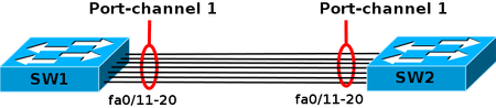
Перед настройкой агрегирования лучше выключить физические интерфейсы. Достаточно отключить их с одной стороны (в примере на sw1), затем настроить агрегирование с двух сторон и включить интерфейсы.
Настройка EtherChannel на sw1:
sw1(config)# interface range f0/11-20
sw1(config-if-range)# shutdown
sw1(config-if-range)# channel-group 1 mode active
Creating a port-channel interface Port-channel 1
Настройка EtherChannel на sw2:
sw2(config)# interface range f0/11-20
sw2(config-if-range)# channel-group 1 mode passive
Creating a port-channel interface Port-channel 1
Включение физических интерфейсов на sw1:
sw1(config-if-range)# no sh
Суммарная информация о состоянии Etherchannel (интерфейсы fa0/19, fa0/20 в режиме standby):
sw1#sh etherchannel summary
Flags:  D - down        P - bundled in port-channel
        I - stand-alone s - suspended
        H - Hot-standby (LACP only)
        R - Layer3      S - Layer2
        U - in use      f - failed to allocate aggregator

        M - not in use, minimum links not met
        u - unsuitable for bundling
        w - waiting to be aggregated
        d - default port


Number of channel-groups in use: 1
Number of aggregators:           1

Group  Port-channel  Protocol    Ports
------+-------------+-----------+-----------------------------------------------
1      Po1(SU)         LACP      Fa0/11(P)   Fa0/12(P)   Fa0/13(P)
                                 Fa0/14(P)   Fa0/15(P)   Fa0/16(P)
                                 Fa0/17(P)   Fa0/18(P)   Fa0/19(H)
                                 Fa0/20(H)
Информация о port-channel на sw1 (интерфейсы fa0/19, fa0/20 в режиме standby):
sw1#sh etherchannel port-channel
               Channel-group listing:
               ----------------------

Group: 1
----------
               Port-channels in the group:
               ---------------------------

Port-channel: Po1    (Primary Aggregator)

------------

Age of the Port-channel   = 0d:00h:03m:08s
Logical slot/port   = 1/0          Number of ports = 8
HotStandBy port = Fa0/19 Fa0/20
Port state          = Port-channel Ag-Inuse
Protocol            =   LACP
Port security       = Disabled

Ports in the Port-channel:

Index   Load   Port     EC state        No of bits
------+------+------+------------------+-----------
  0     00     Fa0/11   Active             0
  0     00     Fa0/12   Active             0
  0     00     Fa0/13   Active             0
  0     00     Fa0/14   Active             0
  0     00     Fa0/15   Active             0
  0     00     Fa0/16   Active             0
  0     00     Fa0/17   Active             0
  0     00     Fa0/18   Active             0

Time since last port bundled:    0d:00h:00m:57s    Fa0/18
Time since last port Un-bundled: 0d:00h:00m:59s    Fa0/19
Информация LACP о локальном коммутаторе (интерфейсы fa0/19, fa0/20 в режиме standby)
sw1#sh lacp internal
Flags:  S - Device is requesting Slow LACPDUs
        F - Device is requesting Fast LACPDUs
        A - Device is in Active mode       P - Device is in Passive mode

Channel group 1
                            LACP port     Admin     Oper    Port        Port
Port      Flags   State     Priority      Key       Key     Number      State
Fa0/11    SA      bndl      32768         0x1       0x1     0xC         0x3D
Fa0/12    SA      bndl      32768         0x1       0x1     0xD         0x3D
Fa0/13    SA      bndl      32768         0x1       0x1     0x16        0x3D
Fa0/14    SA      bndl      32768         0x1       0x1     0x17        0x3D
Fa0/15    SA      bndl      32768         0x1       0x1     0x18        0x3D
Fa0/16    SA      bndl      32768         0x1       0x1     0x19        0x3D
Fa0/17    SA      bndl      32768         0x1       0x1     0xE         0x3D
Fa0/18    SA      bndl      32768         0x1       0x1     0xF         0x3D
Fa0/19    SA      hot-sby   32768         0x1       0x1     0x10        0x5
Fa0/20    SA      hot-sby   32768         0x1       0x1     0x11        0x5
Информация LACP об удаленном коммутаторе:
sw1#sh lacp neighbor
Flags:  S - Device is requesting Slow LACPDUs
        F - Device is requesting Fast LACPDUs
        A - Device is in Active mode       P - Device is in Passive mode

Channel group 1 neighbors

Partner's information:

                  LACP port                        Admin  Oper   Port    Port
Port      Flags   Priority  Dev ID          Age    key    Key    Number  State
Fa0/11    SP      32768     000a.b8ab.eb80  27s    0x0    0x1    0x10E   0x3C
Fa0/12    SP      32768     000a.b8ab.eb80  25s    0x0    0x1    0x10F   0x3C
Fa0/13    SP      32768     000a.b8ab.eb80  27s    0x0    0x1    0x110   0x3C
Fa0/14    SP      32768     000a.b8ab.eb80   6s    0x0    0x1    0x111   0x3C
Fa0/15    SP      32768     000a.b8ab.eb80  26s    0x0    0x1    0x112   0x3C
Fa0/16    SP      32768     000a.b8ab.eb80  27s    0x0    0x1    0x113   0x3C
Fa0/17    SP      32768     000a.b8ab.eb80  25s    0x0    0x1    0x114   0x3C
Fa0/18    SP      32768     000a.b8ab.eb80  27s    0x0    0x1    0x115   0x3C
Fa0/19    SP      32768     000a.b8ab.eb80   2s    0x0    0x1    0x116   0x4
Fa0/20    SP      32768     000a.b8ab.eb80   2s    0x0    0x1    0x117   0x4
Интерфейсы в режиме standby не передают трафик, поэтому по CDP сосед не виден через эти порты:
sw1#sh cdp neighbors
Capability Codes: R - Router, T - Trans Bridge, B - Source Route Bridge
                   S - Switch, H - Host, I - IGMP, r - Repeater, P - Phone

Device ID        Local Intrfce     Holdtme    Capability  Platform  Port ID
sw2              Fas 0/18          123          R S I     WS-C3560- Fas 0/18
sw2              Fas 0/15          179          R S I     WS-C3560- Fas 0/15
sw2              Fas 0/14          179          R S I     WS-C3560- Fas 0/14
sw2              Fas 0/12          179          R S I     WS-C3560- Fas 0/12
sw2              Fas 0/16          178          R S I     WS-C3560- Fas 0/16
sw2              Fas 0/17          178          R S I     WS-C3560- Fas 0/17
sw2              Fas 0/11          178          R S I     WS-C3560- Fas 0/11
sw2              Fas 0/13          178          R S I     WS-C3560- Fas 0/13
sw2              Fas 0/1           147          R S I     WS-C3560- Fas 0/1
Настройка EtherChannel 2го уровня с помощью PAgP
Перед настройкой агрегирования лучше выключить физические интерфейсы. Достаточно отключить их с одной стороны (в примере на sw1), затем настроить агрегирование с двух сторон и включить интерфейсы.
Настройка EtherChannel на sw1:
sw1(config)# interface range f0/11-14
sw1(config-if-range)# shutdown
sw1(config-if-range)# channel-group 2 mode desirable
Creating a port-channel interface Port-channel 2
Настройка EtherChannel на sw2:
sw2(config)# interface range f0/11-14
sw2(config-if-range)# channel-group 2 mode auto
Creating a port-channel interface Port-channel 2
Включение физических интерфейсов на sw1:
sw1(config)# interface range f0/11-14
sw1(config-if-range)# no shut
Просмотр информации
Суммарная информация о состоянии Etherchannel:
sw1#sh etherchannel summary
Flags:  D - down        P - bundled in port-channel
        I - stand-alone s - suspended
        H - Hot-standby (LACP only)
        R - Layer3      S - Layer2
        U - in use      f - failed to allocate aggregator

        M - not in use, minimum links not met
        u - unsuitable for bundling
        w - waiting to be aggregated
        d - default port


Number of channel-groups in use: 1
Number of aggregators:           1

Group  Port-channel  Protocol    Ports
------+-------------+-----------+-----------------------------------------------
2      Po2(SU)         PAgP      Fa0/11(P)   Fa0/12(P)   Fa0/13(P)
                                 Fa0/14(P)
Информация о port-channel на sw1:
sw1#sh etherchannel port-channel
                Channel-group listing:
                ----------------------

Group: 2
----------
                Port-channels in the group:
                ---------------------------

Port-channel: Po2
------------

Age of the Port-channel   = 0d:00h:01m:20s
Logical slot/port   = 1/0          Number of ports = 4
GC                  = 0x00020001      HotStandBy port = null
Port state          = Port-channel Ag-Inuse
Protocol            =   PAgP
Port security       = Disabled

Ports in the Port-channel:

Index   Load   Port     EC state        No of bits
------+------+------+------------------+-----------
  0     00     Fa0/11   Desirable-Sl       0
  0     00     Fa0/12   Desirable-Sl       0
  0     00     Fa0/13   Desirable-Sl       0
  0     00     Fa0/14   Desirable-Sl       0

Time since last port bundled:    0d:00h:00m:59s    Fa0/14
Time since last port Un-bundled: 0d:00h:01m:02s    Fa0/14
Информация PAgP о локальном коммутаторе:
sw1#sh pagp internal
Flags:  S - Device is sending Slow hello.  C - Device is in Consistent state.
        A - Device is in Auto mode.        d - PAgP is down
Timers: H - Hello timer is running.        Q - Quit timer is running.
        S - Switching timer is running.    I - Interface timer is running.

Channel group 2
                                Hello    Partner  PAgP     Learning  Group
Port      Flags State   Timers  Interval Count   Priority   Method  Ifindex
Fa0/11    SC    U6/S7   H       30s      1        128        Any      30
Fa0/12    SC    U6/S7   H       30s      1        128        Any      30
Fa0/13    SC    U6/S7   H       30s      1        128        Any      30
Fa0/14    SC    U6/S7   H       30s      1        128        Any      30
Информация PAgP об удаленном коммутаторе:
sw1#sh pagp neighbor
Flags:  S - Device is sending Slow hello.  C - Device is in Consistent state.
        A - Device is in Auto mode.        P - Device learns on physical port.

Channel group 2 neighbors
          Partner              Partner          Partner         Partner Group
Port      Name                 Device ID        Port       Age  Flags   Cap.
Fa0/11    sw2                  000a.b8ab.eb80   Fa0/11      26s SAC     20001
Fa0/12    sw2                  000a.b8ab.eb80   Fa0/12       4s SAC     20001
Fa0/13    sw2                  000a.b8ab.eb80   Fa0/13      18s SAC     20001
Fa0/14    sw2                  000a.b8ab.eb80   Fa0/14      14s SAC     20001
Счетчики PAgP:
sw1#sh pagp counters
          Information         Flush        PAgP
Port      Sent    Recv     Sent    Recv    Err Pkts
---------------------------------------------------
Channel group: 2
Fa0/11    8       9        0       0       0
Fa0/12    35      6        0       0       0
Fa0/13    50      8        0       0       0
Fa0/14    24      12       0       0       0
Настройка EtherChannel 3го уровня
Настройка EtherChannel 3го уровня очень мало отличается от настройки EtherChannel 2го уровня. Поэтому в этом разделе показан только один пример настройки, с использованием LACP. Остальные варианты настраиваются аналогично, с изменением режима агрегирования. Команды просмотра аналогичны, их можно посмотреть в предыдущих разделах.
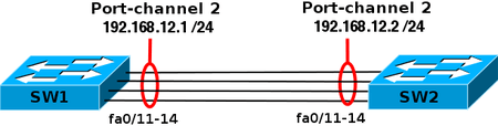
Для EtherChannels 3-го уровня IP-адрес присваивается логическому интерфейсу port-channel, а не физическим интерфейсам.
Перед настройкой агрегирования лучше выключить физические интерфейсы. Достаточно отключить их с одной стороны (в примере на sw1), затем настроить агрегирование с двух сторон и включить интерфейсы.
Настройка логического интерфейса на sw1:
sw1(config)# int port-channel 2
sw1(config-if)# no switchport
sw1(config-if)# ip address 192.168.12.1 255.255.255.0
Настройка физических интерфейсов на sw1:
sw1(config)# int ran fa0/11 - 14
sw1(config-if-range)# shutdown
sw1(config-if-range)# no switchport
sw1(config-if-range)# channel-group 2 mode active
Создание логического интерфейса на sw2:
sw2(config)# int port-channel 2
sw2(config-if)# no switchport
sw2(config-if)# ip address 192.168.12.2 255.255.255.0
Настройка физических интерфейсов на sw2:
sw2(config)# int ran fa0/11 - 14
sw2(config-if-range)# no switchport
sw2(config-if-range)# channel-group 2 mode active
Включение физических интерфейсов на sw1:
sw1(config)# int ran fa0/11 - 14
sw1(config-if-range)# no shutdown
Просмотр информации
Суммарная информация о состоянии Etherchannel:
sw1# show etherchannel summary
Flags:  D - down        P - bundled in port-channel
        I - stand-alone s - suspended
        H - Hot-standby (LACP only)
        R - Layer3      S - Layer2
        U - in use      f - failed to allocate aggregator

        M - not in use, minimum links not met
        u - unsuitable for bundling
        w - waiting to be aggregated
        d - default port


Number of channel-groups in use: 2
Number of aggregators:           2

Group  Port-channel  Protocol    Ports
------+-------------+-----------+-----------------------------------------------
2      Po2(RU)         LACP      Fa0/11(P)   Fa0/12(P)   Fa0/13(P)
                                 Fa0/14(P)
Настройка агрегирования каналов на маршрутизаторе
Особенности настройки агрегирования на маршрутизаторе:
- Поддерживается только статическое агрегирование, без использования протоколов
- Можно создать только 2 агрегированных интерфейса
- Максимальное количество интерфейсов в EtherChannel – 4
- Метод балансировки использует IP-адреса отправителя и получателя, включен по умолчанию и не может быть изменен
- Агрегировать можно только те интерфейсы, которые находятся на модулях одинакового типа
Создание агрегированного интерфейса на маршрутизаторе:
R1(config)# interface port-channel 1
router(config-if)# ip address 10.0.1.101 255.255.255.0
Добавление физических интерфейсов в EtherChannel:
R1(config)# interface range fa0/0 - 1
R1(config-if-range)# channel-group 1
FastEthernet0/0 added as member-1 to port-channel1
FastEthernet0/1 added as member-2 to port-channel1
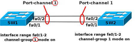
Пример настройки агрегирования каналов между коммутатором и маршрутизатором
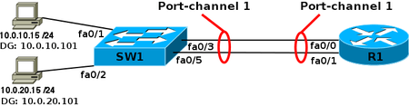
Конфигурация R1:
interface FastEthernet0/0
 channel-group 1
!
interface FastEthernet0/1
 channel-group 1
!
interface Port-channel1
 ip address 10.0.1.101 255.255.255.0
!
interface Port-channel1.10
 encapsulation dot1Q 10
 ip address 10.0.10.101 255.255.255.0
!
interface Port-channel1.20
 encapsulation dot1Q 20
 ip address 10.0.20.101 255.255.255.0
Конфигурация sw1:
interface FastEthernet0/3
 switchport mode trunk
 channel-group 1 mode on
!
interface FastEthernet0/5
 switchport mode trunk
 channel-group 1 mode on
!
interface Port-channel1
 switchport mode trunk
Информация о etherchannel на sw1:
sw2#show etherchannel summary
Flags:  D - down        P - bundled in port-channel
        I - stand-alone s - suspended
        H - Hot-standby (LACP only)
        R - Layer3      S - Layer2
        U - in use      f - failed to allocate aggregator

        M - not in use, minimum links not met
        u - unsuitable for bundling
        w - waiting to be aggregated
        d - default port


Number of channel-groups in use: 1
Number of aggregators:           1

Group  Port-channel  Protocol    Ports
------+-------------+-----------+-----------------------------------------------
1      Po1(SU)          -        Fa0/3(P)    Fa0/5(P)
r1#sh int port-channel 1
Port-channel1 is up, line protocol is up
 Hardware is FEChannel, address is 001b.d4f0.1098 (bia 001b.d4f0.1098)
 Internet address is 10.0.1.101/24
 MTU 1500 bytes, BW 200000 Kbit, DLY 100 usec,
    reliability 255/255, txload 1/255, rxload 1/255
 Encapsulation 802.1Q Virtual LAN, Vlan ID  1., loopback not set
 Keepalive set (10 sec)
 ARP type: ARPA, ARP Timeout 04:00:00
   No. of active members in this channel: 2
       Member 0 : FastEthernet0/0 , Full-duplex, 100Mb/s
       Member 1 : FastEthernet0/1 , Full-duplex, 100Mb/s
   No. of Non-active members in this channel: 0
 Last input never, output never, output hang never
 Last clearing of "show interface" counters never
 Input queue: 0/150/0/0 (size/max/drops/flushes); Total output drops: 0
 Queueing strategy: fifo
 Output queue: 0/80 (size/max)
 5 minute input rate 0 bits/sec, 0 packets/sec
 5 minute output rate 0 bits/sec, 0 packets/sec
    0 packets input, 0 bytes
    Received 0 broadcasts, 0 runts, 0 giants, 0 throttles
    0 input errors, 0 CRC, 0 frame, 0 overrun, 0 ignored
    0 watchdog
    0 input packets with dribble condition detected
    9 packets output, 564 bytes, 0 underruns
    0 output errors, 0 collisions, 0 interface resets
    0 babbles, 0 late collision, 0 deferred
    0 lost carrier, 0 no carrier
    0 output buffer failures, 0 output buffers swapped out
Балансировка нагрузки
Метод балансировки нагрузки повлияет на распределение трафика во всех EtherChannel, которые созданы на коммутаторе.
В зависимости от модели коммутатора, могут поддерживаться такие методы балансировки:
- по MAC-адресу отправителя или MAC-адресу получателя или учитывая оба адреса
- по IP-адресу отправителя или IP-адресу получателя или учитывая оба адреса
- по номеру порта отправителя или номеру порта получателя или учитывая оба порта
Пример вариантов на коммутаторе 3560:
sw1(config)# port-channel load-balance ?
  dst-ip       Dst IP Addr
  dst-mac      Dst Mac Addr
  src-dst-ip   Src XOR Dst IP Addr
  src-dst-mac  Src XOR Dst Mac Addr
  src-ip       Src IP Addr
  src-mac      Src Mac Addr
При выборе метода балансировки, необходимо учитывать топологию сети, каким образом передается трафик.
Например, на схеме, все устройства находятся в одном VLAN. Шлюз по умолчанию маршрутизатор R1.
Если коммутатор sw2 использует метод балансировки по MAC-адресу отправителя, то балансировка выполняться не будет, так как у всех фреймов MAC-адрес отправителя будет адрес маршрутизатора R1:
Аналогично, если коммутатор sw1 использует метод балансировки по MAC-адресу получателя, то балансировка выполняться не будет, так как у всех фреймов, которые будут проходить через агрегированный канал, MAC-адрес получателя будет адрес маршрутизатора R1:
Определение текущего метода балансировки:
sw1# show etherchannel load-balance
Тестирование балансировки нагрузки
Для того чтобы проверить через какой интерфейс, при настроенном методе балансировки, пойдет конкретный пакет или фрейм, можно использовать команду test etherchannel load-balance.
Проверка при задании IP-адресов:
sw1# test etherchannel load-balance int port-channel 1 ip 192.168.1.1 192.168.1.2
Would select Fa0/11 of Po1
Пример тестирования при задании MAC-адресов:
sw2# test etherchannel load-balance int po 3 mac 0000.0001.0601 0000.0002.0005
Would select Fa0/12 of Po3

sw2# test etherchannel load-balance int po 3 mac 0000.0001.0600 0000.0002.0005
Would select Fa0/11 of Po3

sw2# test etherchannel load-balance int po 3 mac 0000.0001.0800 0000.0002.0005
Would select Fa0/14 of Po3

sw2# test etherchannel load-balance int po 3 mac 0000.0001.1800 0000.0002.0005
Would select Fa0/11 of Po3
Взаимодействие Etherchannel с другими функциями
- Dynamic Trunking Protocol (DTP) и Cisco Discovery Protocol (CDP) отправляют и получают пакеты через физические интерфейсы в EtherChannel.
- Trunk ports отправляют и получают PAgP и LACP PDU через VLAN с наименьшим номером.
- Spanning tree отправляет пакеты через первый интерфейс в EtherChannel.
- MAC-адрес EtherChannel 3го уровня это MAC-адрес первого порта в port-channel.
- PAgP отправляет и получает PAgP PDU только с интерфейсов на которых PAgP включен в режиме
autoилиdesirable. - LACP отправляет и получает LACP PDU только с интерфейсов на которых LACP включен в режиме
activeилиpassive.