«IEEE 802.3ad» redirects here. Not to be confused with IEEE 802.1ad.
In computer networking, link aggregation is the combining (aggregating) of multiple network connections in parallel by any of several methods. Link aggregation increases total throughput beyond what a single connection could sustain, and provides redundancy where all but one of the physical links may fail without losing connectivity. A link aggregation group (LAG) is the combined collection of physical ports.

Other umbrella terms used to describe the concept include trunking,[1] bundling,[2] bonding,[1] channeling[3] or teaming.
Implementation may follow vendor-independent standards such as Link Aggregation Control Protocol (LACP) for Ethernet, defined in IEEE 802.1AX or the previous IEEE 802.3ad, but also proprietary protocols.
Motivation
Edit
Link aggregation increases the bandwidth and resilience of Ethernet connections.
Bandwidth requirements do not scale linearly. Ethernet bandwidths historically have increased tenfold each generation: 10 megabit/s, 100 Mbit/s, 1000 Mbit/s, 10,000 Mbit/s. If one started to bump into bandwidth ceilings, then the only option was to move to the next generation, which could be cost prohibitive. An alternative solution, introduced by many of the network manufacturers in the early 1990s, is to use link aggregation to combine two physical Ethernet links into one logical link. Most of these early solutions required manual configuration and identical equipment on both sides of the connection.[4]
There are three single points of failure inherent to a typical port-cable-port connection, in either a computer-to-switch or a switch-to-switch configuration: the cable itself or either of the ports the cable is plugged into can fail. Multiple logical connections can be made, but many of the higher level protocols were not designed to fail over completely seamlessly. Combining multiple physical connections into one logical connection using link aggregation provides more resilient communications.
Architecture
Edit
Network architects can implement aggregation at any of the lowest three layers of the OSI model. Examples of aggregation at layer 1 (physical layer) include power line (e.g. IEEE 1901) and wireless (e.g. IEEE 802.11) network devices that combine multiple frequency bands. OSI layer 2 (data link layer, e.g. Ethernet frame in LANs or multi-link PPP in WANs, Ethernet MAC address) aggregation typically occurs across switch ports, which can be either physical ports or virtual ones managed by an operating system. Aggregation at layer 3 (network layer) in the OSI model can use round-robin scheduling, hash values computed from fields in the packet header, or a combination of these two methods.
Regardless of the layer on which aggregation occurs, it is possible to balance the network load across all links. However, in order to avoid out-of-order delivery, not all implementations take advantage of this. Most methods provide failover as well.
Combining can either occur such that multiple interfaces share one logical address (i.e. IP) or one physical address (i.e. MAC address), or it allows each interface to have its own address. The former requires that both ends of a link use the same aggregation method, but has performance advantages over the latter.
Channel bonding is differentiated from load balancing in that load balancing divides traffic between network interfaces on per network socket (layer 4) basis, while channel bonding implies a division of traffic between physical interfaces at a lower level, either per packet (layer 3) or a data link (layer 2) basis.[citation needed]
IEEE link aggregation
Edit
Standardization process
Edit
By the mid-1990s, most network switch manufacturers had included aggregation capability as a proprietary extension to increase bandwidth between their switches. Each manufacturer developed its own method, which led to compatibility problems. The IEEE 802.3 working group took up a study group to create an interoperable link layer standard (i.e. encompassing the physical and data-link layers both) in a November 1997 meeting.[4] The group quickly agreed to include an automatic configuration feature which would add in redundancy as well. This became known as Link Aggregation Control Protocol (LACP).
802.3ad
Edit
As of 2000, most gigabit channel-bonding schemes used the IEEE standard of link aggregation which was formerly clause 43 of the IEEE 802.3 standard added in March 2000 by the IEEE 802.3ad task force.[5] Nearly every network equipment manufacturer quickly adopted this joint standard over their proprietary standards.
802.1AX
Edit
The 802.3 maintenance task force report for the 9th revision project in November 2006 noted that certain 802.1 layers (such as 802.1X security) were positioned in the protocol stack below link aggregation which was defined as an 802.3 sublayer.[6] To resolve this discrepancy, the 802.3ax (802.1AX) task force was formed,[7] resulting in the formal transfer of the protocol to the 802.1 group with the publication of IEEE 802.1AX-2008 on 3 November 2008.[8]
Link Aggregation Control Protocol
Edit
Within the IEEE Ethernet standards, the Link Aggregation Control Protocol (LACP) provides a method to control the bundling of several physical links together to form a single logical link. LACP allows a network device to negotiate an automatic bundling of links by sending LACP packets to their peer, a directly connected device that also implements LACP.
LACP Features and practical examples
- Maximum number of bundled ports allowed in the port channel: Valid values are usually from 1 to 8.
- LACP packets are sent with multicast group MAC address 01:80:C2:00:00:02
- During LACP detection period
- LACP packets are transmitted every second
- Keep-alive mechanism for link member: (default: slow = 30s, fast=1s)[specify]
- Selectable load-balancing mode is available in some implementations[9]
- LACP mode :
- Active: Enables LACP unconditionally.
- Passive: Enables LACP only when an LACP device is detected. (This is the default state)[specify]
Advantages over static configuration
Edit
- Failover occurs automatically: When a link has an intermediate failure, for example in a media converter between the devices, a peer system may not perceive any connectivity problems. With static link aggregation, the peer would continue sending traffic down the link causing the connection to fail.
- Dynamic configuration: The device can confirm that the configuration at the other end can handle link aggregation. With static link aggregation, a cabling or configuration mistake could go undetected and cause undesirable network behavior.[10]
Practical notes
Edit
LACP works by sending frames (LACPDUs) down all links that have the protocol enabled. If it finds a device on the other end of a link that also has LACP enabled, that device will independently send frames along the same links in the opposite direction enabling the two units to detect multiple links between themselves and then combine them into a single logical link. LACP can be configured in one of two modes: active or passive. In active mode, LACPDUs are sent 1 per second along the configured links. In passive mode, LACPDUs are not sent until one is received from the other side, a speak-when-spoken-to protocol.
Proprietary link aggregation
Edit
In addition to the IEEE link aggregation substandards, there are a number of proprietary aggregation schemes including Cisco’s EtherChannel and Port Aggregation Protocol, Juniper’s Aggregated Ethernet, AVAYA’s Multi-Link Trunking, Split Multi-Link Trunking, Routed Split Multi-Link Trunking and Distributed Split Multi-Link Trunking, ZTE’s Smartgroup, Huawei’s Eth-Trunk, and Connectify’s Speedify.[11] Most high-end network devices support some form of link aggregation. Software-based implementations – such as the *BSD lagg package, Linux bonding driver, Solaris dladm aggr, etc. – exist for many operating systems.
Linux drivers
Edit
The Linux bonding driver[12] provides a method for aggregating multiple network interface controllers (NICs) into a single logical bonded interface of two or more so-called (NIC) slaves. The majority of modern Linux distributions come with a Linux kernel which has the Linux bonding driver integrated as a loadable kernel module and the ifenslave (if = [network] interface) user-level control program pre-installed. Donald Becker programmed the original Linux bonding driver. It came into use with the Beowulf cluster patches for the Linux kernel 2.0.
Modes for the Linux bonding driver[12] (network interface aggregation modes) are supplied as parameters to the kernel bonding module at load time. They may be given as command-line
arguments to the insmod or modprobe commands, but are usually specified in a Linux distribution-specific configuration file. The behavior of the single logical bonded interface depends upon its specified bonding driver mode. The default parameter is balance-rr.
- Round-robin (balance-rr)
- Transmit alternate network packets in sequential order from the first available NIC slave through the last. This mode provides load balancing and fault tolerance.[13] This mode can cause congestion control issues due to the packet reordering it can introduce.[14]
- Active-backup (active-backup)
- Only one NIC slave in the bond is active. A different slave becomes active if, and only if, the active slave fails. The single logical bonded interface’s MAC address is externally visible on only one NIC (port) to simplify forwarding in the network switch. This mode provides fault tolerance.
- XOR (balance-xor)
- Transmit network packets based on a hash of the packet’s source and destination. The default algorithm only considers MAC addresses (layer2). Newer versions allow selection of additional policies based on IP addresses (layer2+3) and TCP/UDP port numbers (layer3+4). This selects the same NIC slave for each destination MAC address, IP address, or IP address and port combination, respectively. Single connections will have guaranteed in order packet delivery and will transmit at the speed of a single NIC.[15] This mode provides load balancing and fault tolerance.
- Broadcast (broadcast)
- Transmit network packets on all slave network interfaces. This mode provides fault tolerance.
- IEEE 802.3ad Dynamic link aggregation (802.3ad, LACP)
- Creates aggregation groups that share the same speed and duplex settings. Utilizes all slave network interfaces in the active aggregator group according to the 802.3ad specification. This mode is similar to the XOR mode above and supports the same balancing policies. The link is set up dynamically between two LACP-supporting peers.
- Adaptive transmit load balancing (balance-tlb)
- Linux bonding driver mode that does not require any special network-switch support. The outgoing network packet traffic is distributed according to the current load (computed relative to the speed) on each network interface slave. Incoming traffic is received by one currently designated slave network interface. If this receiving slave fails, another slave takes over the MAC address of the failed receiving slave.
- Adaptive load balancing (balance-alb)
- includes balance-tlb plus receive load balancing (rlb) for IPv4 traffic and does not require any special network switch support. The receive load balancing is achieved by ARP negotiation. The bonding driver intercepts the ARP Replies sent by the local system on their way out and overwrites the source hardware address with the unique hardware address of one of the NIC slaves in the single logical bonded interface such that different network-peers use different MAC addresses for their network packet traffic.
The Linux Team driver[16] provides an alternative to bonding driver. The main difference is that Team driver kernel part contains only essential code and the rest of the code (link validation, LACP implementation, decision making, etc.) is run in userspace as a part of teamd daemon.
Usage
Edit
Network backbone
Edit
Link aggregation offers an inexpensive way to set up a high-capacity backbone network that transfers multiple times more data than any single port or device can deliver. Link aggregation also allows the network’s backbone speed to grow incrementally as demand on the network increases, without having to replace everything and deploy new hardware.
Most backbone installations install more cabling or fiber optic pairs than is initially necessary. This is done because labor costs are higher than the cost of the cable, and running extra cable reduces future labor costs if networking needs change. Link aggregation can allow the use of these extra cables to increase backbone speeds for little or no extra cost if ports are available.
Order of frames
Edit
When balancing traffic, network administrators often wish to avoid reordering Ethernet frames. For example, TCP suffers additional overhead when dealing with out-of-order packets. This goal is approximated by sending all frames associated with a particular session across the same link. Common implementations use L2 or L3 hashes (i.e. based on the MAC or the IP addresses), ensuring that the same flow is always sent via the same physical link.[17][18][19]
However, this may not provide even distribution across the links in the trunk when only a single or very few pairs of hosts communicate with each other, i.e. when the hashes provide too little variation. It effectively limits the client bandwidth in aggregate.[18] In the extreme, one link is fully loaded while the others are completely idle and aggregate bandwidth is limited to this single member’s maximum bandwidth. For this reason, an even load balancing and full utilization of all trunked links is almost never reached in real-life implementations.
Use on network interface cards
Edit
NICs trunked together can also provide network links beyond the throughput of any one single NIC. For example, this allows a central file server to establish an aggregate 2-gigabit connection using two 1-gigabit NICs teamed together. Note the data signaling rate will still be 1 Gbit/s, which can be misleading depending on methodologies used to test throughput after link aggregation is employed.
Microsoft Windows
Edit
Microsoft Windows Server 2012 supports link aggregation natively. Previous Windows Server versions relied on manufacturer support of the feature within their device driver software. Intel, for example, released Advanced Networking Services (ANS) to bond Intel Fast Ethernet and Gigabit cards.[20]
Nvidia supports teaming with their Nvidia Network Access Manager/Firewall Tool. HP has a teaming tool for HP-branded NICs which supports several modes of link aggregation including 802.3ad with LACP. In addition, there is a basic layer-3 aggregation[21] that allows servers with multiple IP interfaces on the same network to perform load balancing, and for home users with more than one internet connection, to increase connection speed by sharing the load on all interfaces.[22]
Broadcom offers advanced functions via Broadcom Advanced Control Suite (BACS), via which the teaming functionality of BASP (Broadcom Advanced Server Program) is available, offering 802.3ad static LAGs, LACP, and «smart teaming» which doesn’t require any configuration on the switches to work. It is possible to configure teaming with BACS with a mix of NICs from different vendors as long as at least one of them is from Broadcom and the other NICs have the required capabilities to support teaming.[23]
Linux and UNIX
Edit
Linux, FreeBSD, NetBSD, OpenBSD, macOS, OpenSolaris and commercial Unix distributions such as AIX implement Ethernet bonding at a higher level and, as long as the NIC is supported by the kernel, can deal with NICs from different manufacturers or using different drivers.[12]
Virtualization platforms
Edit
Citrix XenServer and VMware ESX have native support for link aggregation. XenServer offers both static LAGs as well as LACP. vSphere 5.1 (ESXi) supports both static LAGs and LACP natively with their virtual distributed switch.[24]
Microsoft’s Hyper-V does not offer link aggregation support from the hypervisor level, but the above-mentioned methods for teaming under Windows apply to Hyper-V.
Limitations
Edit
Single switch
Edit
With the modes balance-rr, balance-xor, broadcast and 802.3ad, all physical ports in the link aggregation group must reside on the same logical switch, which, in most common scenarios, will leave a single point of failure when the physical switch to which all links are connected goes offline. The modes active-backup, balance-tlb, and balance-alb can also be set up with two or more switches. But after failover (like all other modes), in some cases, active sessions may fail (due to ARP problems) and have to be restarted.
However, almost all vendors have proprietary extensions that resolve some of this issue: they aggregate multiple physical switches into one logical switch. Nortel’s split multi-link trunking (SMLT) protocol allows multiple Ethernet links to be split across multiple switches in a stack, preventing any single point of failure and additionally allowing all switches to be load balanced across multiple aggregation switches from the single access stack. These devices synchronize state across an Inter-Switch Trunk (IST) such that they appear to the connecting (access) device to be a single device (switch block) and prevent any packet duplication. SMLT provides enhanced resiliency with sub-second failover and sub-second recovery for all speed trunks while operating transparently to end-devices.
Multi-chassis link aggregation group provides similar features in a vendor-nonspecific manner. To the connected device, the connection appears as a normal link aggregated trunk. The coordination between the multiple sources involved is handled in a vendor-specific manner.
Same link speed
Edit
In most implementations, all the ports used in an aggregation consist of the same physical type, such as all copper ports (10/100/1000BASE‑T), all multi-mode fiber ports, or all single-mode fiber ports. However, all the IEEE standard requires is that each link be full duplex and all of them have an identical speed (10, 100, 1,000 or 10,000 Mbit/s).
Many switches are PHY independent, meaning that a switch could have a mixture of copper, SX, LX, LX10 or other GBIC/SFP modular transceivers. While maintaining the same PHY is the usual approach, it is possible to aggregate a 1000BASE-SX fiber for one link and a 1000BASE-LX (longer, diverse path) for the second link. One path may have a longer propagation time but since most implementations keep a single traffic flow on the same physical link (using a hash of either MAC addresses, IP addresses, or IP/transport-layer port combinations as index) this doesn’t cause problematic out-of-order delivery.
Ethernet aggregation mismatch
Edit
Aggregation mismatch refers to not matching the aggregation type on both ends of the link. Some switches do not implement the 802.1AX standard but support static configuration of link aggregation. Therefore, link aggregation between similarly statically configured switches may work but will fail between a statically configured switch and a device that is configured for LACP.
Examples
Edit
Ethernet
Edit
On Ethernet interfaces, channel bonding requires assistance from both the Ethernet switch and the host computer’s operating system, which must stripe the delivery of frames across the network interfaces in the same manner that I/O is striped across disks in a RAID 0 array.[citation needed] For this reason, some discussions of channel bonding also refer to Redundant Array of Inexpensive Nodes (RAIN) or to redundant array of independent network interfaces.[25]
Modems
Edit
In analog modems, multiple dial-up links over POTS may be bonded. Throughput over such bonded connections can come closer to the aggregate bandwidth of the bonded links than can throughput under routing schemes which simply load-balance outgoing network connections over the links.
DSL
Edit
Similarly, multiple DSL lines can be bonded to give higher bandwidth; in the United Kingdom, ADSL is sometimes bonded to give for example 512 kbit/s upload bandwidth and 4 megabit/s download bandwidth, in areas that only have access to 2 megabit/s bandwidth.[citation needed]
DOCSIS
Edit
Under the DOCSIS 3.0 and 3.1 specifications for data over cable TV systems, multiple channels may be bonded. Under DOCSIS 3.0, up to 32 downstream and 8 upstream channels may be bonded.[26] These are typically 6 or 8 MHz wide. DOCSIS 3.1 defines more complicated arrangements involving aggregation at the level of subcarriers and larger notional channels.[27]
Wireless Broadband
Edit
Broadband bonding is a type of channel bonding that refers to aggregation of multiple channels at OSI layers at level four or above. Channels bonded can be wired links such as a T-1 or DSL line. Additionally, it is possible to bond multiple cellular links for an aggregated wireless bonded link.
Previous bonding methodologies resided at lower OSI layers, requiring coordination with telecommunications companies for implementation. Broadband bonding, because it is implemented at higher layers, can be done without this coordination.[28]
Commercial implementations of Broadband Channel Bonding include:
- Wistron AiEdge Corporation’s U-Bonding Technology [29]
- Mushroom Networks’ Broadband Bonding Service [30]
- Connectify’s Speedify fast bonding VPN — software app for multiple platforms: PC, Mac, iOS and Android [31]
- Peplink’s SpeedFusion Bonding Technology [32]
- Viprinet’s Multichannel VPN Bonding Technology [33]
- Elsight’s Multichannel Secure Data Link [34]
- Synopi’s Natiply Internet Bonding Technology [35]
- ComBOX Networks multi-wan bonding as a service [36]
Wi-Fi
Edit
- On 802.11 (Wi-Fi), channel bonding is used in Super G technology, referred to as 108Mbit/s. It bonds two channels of standard 802.11g, which has 54Mbit/s data signaling rate.
- On IEEE 802.11n, a mode with a channel width of 40 MHz is specified. This is not channel bonding, but a single channel with double the older 20 MHz channel width, thus using two adjacent 20 MHz bands. This allows direct doubling of the PHY data rate from a single 20 MHz channel, but the MAC and user-level throughput also depends on other factors so may not double.[citation needed]
See also
Edit
- FlexE
- Inverse multiplexer
- Spanning Tree Protocol
References
Edit
- ^ a b Guijarro, Manuel; Ruben Gaspar; et al. (2008). «Experience and Lessons learnt from running High Availability Databases on Network Attached Storage» (PDF). Journal of Physics: Conference Series. Conference Series. IOP Publishing. 119 (4): 042015. Bibcode:2008JPhCS.119d2015G. doi:10.1088/1742-6596/119/4/042015. Retrieved 2009-08-17.
Network bonding (also known as port trunking) consists of aggregating multiple network interfaces into a single logical bonded interface that correspond to a single IP address.
- ^ «IEEE 802.3ad Link Bundling». Cisco Systems. 2007-02-27. Archived from the original on 2012-04-19. Retrieved 2012-03-15.
- ^ «Cisco Nexus 5000 Series NX-OS Software Configuration Guide — Configuring Port Channels [Cisco Nexus 5000 Series Switches]». Cisco. Retrieved 2019-10-25.
- ^ a b «IEEE 802 Trunking Tutorial». 1997-11-11. Archived from the original on 2013-12-07. Retrieved 2013-08-13.
- ^ «IEEE 802.3ad Link Aggregation Task Force». www.ieee802.org. Archived from the original on 27 October 2017. Retrieved 9 May 2018.
- ^ Law, David (2006-11-13). «IEEE 802.3 Maintenance» (PDF). p. 9. Archived (PDF) from the original on 2008-10-07. Retrieved 2009-08-18.
Proposal to move Link Aggregation to IEEE 802.1 •It is an 802.3 sublayer but it has to go above IEEE Std 802.1x
- ^ «IEEE 802.3ax (IEEE P802.1AX) Link Aggregation Project Authorization Request (approved)» (PDF). 2007-03-22. p. 3. Archived from the original (PDF) on 2010-11-16. Retrieved 2018-01-10.
It has been concluded between 802.1 and 802.3 that future development of Link Aggregation would be more appropriate as an 802.1 standard
- ^ «IEEE SA — 802.1AX-2008 — IEEE Standard for Local and metropolitan area networks—Link Aggregation». Archived from the original on 2013-08-07. Retrieved 2013-08-13.
- ^ «What Is LACP?». Retrieved 5 March 2020.
- ^ «Link aggregation on Dell servers» (PDF). Archived from the original (PDF) on 13 March 2012.
- ^ «Connectify commercializes Speedify channel bonding service — FierceWireless». www.fiercewireless.com. Archived from the original on 28 June 2016. Retrieved 9 May 2018.
- ^ a b c The Linux Foundation: Bonding Archived 2010-12-28 at the Wayback Machine
- ^ «Understanding NIC Bonding with Linux». 2 December 2009.
- ^ «Linux Ethernet Bonding Driver HOWTO». Retrieved 2021-11-27.
- ^ https://www.kernel.org/doc/Documentation/networking/bonding.txt[bare URL plain text file]
- ^ «libteam by jpirko». www.libteam.org. Archived from the original on 14 September 2017. Retrieved 9 May 2018.
- ^ «IEEE 802.3ad Link Aggregation (LAG) what it is, and what it is not» (PDF). Archived (PDF) from the original on 2007-11-29. Retrieved 2007-05-14.[unreliable source?]
- ^ a b Mechanisms for Optimizing Link Aggregation Group (LAG) and Equal-Cost Multipath (ECMP) Component Link Utilization in Networks. doi:10.17487/RFC7424. RFC 7424.
- ^ «Outbound Traffic Distribution Across Trunked Links». Procurve 2910al Management and Configuration Guide. Hewlett Packard. February 2009.
- ^ Intel Advanced Networking Services Archived 2007-01-24 at the Wayback Machine
- ^ Archiveddocs. «RandomAdapter: Core Services». technet.microsoft.com. Archived from the original on 25 April 2016. Retrieved 9 May 2018.
- ^ «Norton Internet Security™ — PC Protection». www.pctools.com. Archived from the original on 1 April 2017. Retrieved 9 May 2018.
- ^ Broadcom Windows Management Applications Archived 2012-08-01 at the Wayback Machine, visited 8 July 2012
- ^ «What’s New in vSphere 5.1 networking» (PDF). June 2012. Archived from the original (PDF) on 2014-01-23.
- ^
Jielin Dong, ed. (2007). Network Dictionary. ITPro collection. Javvin Technologies Inc. p. 95. ISBN 9781602670006. Retrieved 2013-08-07.Channel bonding, sometimes also called redundant array of independent network interfaces (RAIN), is an arrangement in which two or more network interfaces on a host computer are combined for redundancy or increased throughput.
- ^ DOCSIS 3.0 Physical Interface Specification
- ^ DOCSIS 3.1 Physical Interface Specification
- ^ «Broadband bonding offers high-speed alternative». engineeringbook.net. Archived from the original on 7 July 2012. Retrieved 5 April 2013.
- ^ «Ubonding | Wistron». 17 November 2022.
- ^ Mushroom Networks’ Broadband Bonding Service
- ^ Connectify’s Speedify Service
- ^ Peplink’s SpeedFusion Bonding Technology
- ^ Viprinet’s Multichannel VPN Bonding Technology
- ^ Elsight Multichannel Secure Data Link
- ^ Synopi’s Natiply Internet Bonding Technology
- ^ comBOX multi-wan services Broadband bonding
- General
- «Chapter 5.4: Link Aggregation Control Protocol (LACP)». IEEE Std 802.1AX-2008 IEEE Standard for Local and Metropolitan Area Networks — Link Aggregation (PDF). IEEE Standards Association. 2008-11-03. p. 30. doi:10.1109/IEEESTD.2008.4668665. ISBN 978-0-7381-5794-8.
- Tech Tips — Bonding Modes
External links
Edit
- IEEE P802.3ad Link Aggregation Task Force
- Mikrotik link Aggregation / Bonding Guide
- Configuring a Shared Ethernet Adapter (SEA) — IBM
- Managing VLANs on mission-critical shared Ethernet adapters — IBM
- Network overview by Rami Rosen (section about bonding)
Агрегирование каналов связи (Link Aggregation) — это объединение нескольких физических портов в одну логическую магистраль на канальном уровне модели OSI с целью образования высокоскоростного канала передачи данных и повышения отказоустойчивости.
Все избыточные связи в одном агрегированном канале остаются в рабочем состоянии, а имеющийся трафик распределяется между ними для достижения балансировки нагрузки. При отказе одной из линий, входящих в такой логический канал, трафик распределяется между оставшимися линиями.
Включённые в агрегированный канал порты называются членами группы агрегирования (Link Aggregation Group). Один из портов в группе выступает в качестве мастера-порта (master port). Так как все порты агрегированной группы должны работать в одном режиме, конфигурация мастера-порта распространяется на все порты в группе.
Важным моментом при реализации объединения портов в агрегированный канал является распределение трафика по ним. Выбор порта для конкретного сеанса выполняется на основе выбранного алгоритма агрегирования портов, то есть на основании некоторых признаков поступающих пакетов.
В коммутаторах D-Link like CLI по умолчанию используется алгоритм mac_source.
Программное обеспечение коммутаторов D-Link поддерживает два типа агрегирования каналов связи: статическое и динамическое, на основе стандарта IEEE 802.3ad (LACP).
При статическом агрегировании каналов (используется по умолчанию), все настройки на коммутаторах выполняются вручную, и они не допускают динамических изменений в агрегированной группе.
Для организации динамического агрегирования каналов между коммутаторами и другими сетевыми устройствами используется протокол управления агрегированным каналом – Link Aggregation Control Protocol (LACP). Протокол LACP определяет метод управления объединением нескольких физических портов в одну логическую группу и предоставляет сетевым устройствам возможность автосогласования каналов, путём отправки управляющих кадров протокола LACP непосредственно подключённым устройствам с поддержкой LACP. Порты, на которых активизирован протокол LACP, могут быть настроены для работы в одном из двух режимов: активном (active) или пассивном (passive). При работе в активном режиме порты выполняют обработку и рассылку управляющих кадров протокола LACP. При работе в пассивном режиме порты выполняют только обработку управляющих кадров LACP.
Примечание к настройке
Рассматриваемый пример настройки подходит для коммутаторов с D-Link-like CLI.
Задача
В локальной сети необходимо увеличить пропускную способность канала связи между коммутаторами. Задача решается при помощи агрегирования пропускной способности портов на коммутаторах с использованием протокола LACP.

Рис. 1 Схема подключения
Примечание
Не соединяйте физически соответствующие порты коммутаторов до тех пор, пока не настроено агрегирование каналов, так как в коммутируемой сети может возникнуть петля.
Настройка коммутатора SW 1
- Включите агрегацию каналов:
config link_aggregation state enable
- Создайте группу агрегирования каналов:
create link_aggregation group_id 1 type lacp
- Включите порты 1—8 в группу агрегирования каналов и выберите порт 1 в качестве мастера-порта (команда вводится в одну строку):
config link_aggregation group_id 1 master_port 1 ports 1-8 state enable
- Настройте порты на работу в пассивном режиме:
config lacp_port 1-8 mode passive
- Проверьте выполненные настройки:
- Проверьте режим работы LACP на портах коммутаторов:
- Посмотрите текущий алгоритм агрегирования каналов:
show link_aggregation algorithm
Настройка коммутатора SW 2
- Включите агрегацию каналов:
config link_aggregation state enable
- Создайте группу агрегирования каналов:
create link_aggregation group_id 1 type lacp
- Включите порты 1—8 в группу агрегирования каналов и выберите порт 1 в качестве мастера-порта (команда вводится в одну строку):
config link_aggregation group_id 1 master_port 1 ports 1-8 state enable
- Настройте порты на работу в активном режиме:
config lacp_port 1-8 mode active
- Проверьте выполненные настройки:
- Проверьте режим работы LACP на портах коммутаторов:
- Посмотрите текущий алгоритм агрегирования каналов:
show link_aggregation algorithm
Table Of Contents
Link Aggregation Control Protocol (LACP) (802.3ad) for Gigabit Interfaces
Contents
Prerequisites for LACP (802.3ad) for Gigabit Interfaces
Restrictions for LACP (802.3ad) for Gigabit Interfaces
Information About LACP (802.3ad) for Gigabit Interfaces
LACP (802.3ad) for Gigabit Interfaces Feature Overview
Features Supported on Gigabit EtherChannel Bundles
LACP (802.3ad) for Gigabit Interfaces Configuration Overview
Understanding LACP (802.3ad) for Gigabit Interfaces Load Balancing
Understanding LACP (802.3ad) for Gigabit Interfaces Configuration
LACP (802.3ad) for Gigabit Interfaces Configuration Guidelines
How to Configure LACP (802.3ad) for Gigabit Interfaces
Configuring LACP (802.3ad) for Gigabit Interfaces
Examples
Configuring the LACP System ID and Port Priority
Examples
Removing a Channel Group from a Port
Examples
Displaying Gigabit EtherChannel Information
Configuration Examples for LACP (802.3ad) for Gigabit Interfaces
Configuring LACP (802.3ad) for Gigabit Interfaces: Example
Displaying Port Channel Interface Information: Example
Additional References
Related Documents
Standards
MIBs
RFCs
Technical Assistance
Command Reference
lacp max-bundle
Feature Information for LACP (802.3ad) for Gigabit Interfaces
Link Aggregation Control Protocol (LACP) (802.3ad) for Gigabit Interfaces
First Published: November, 2006
Revised: March, 2007
This document describes how to configure Gigabit Ethernet port channels using LACP. This allows you to bundle multiple Gigabit Ethernet links into a single logical interface on a Cisco 10000 series router.
Finding Feature Information in This Module
Your Cisco IOS software release may not support all of the features documented in this module. To reach links to specific feature documentation in this module and to see a list of the releases in which each feature is supported, use the «Feature Information for LACP (802.3ad) for Gigabit Interfaces» section.
Finding Support Information for Platforms and Cisco IOS Software Images
Use Cisco Feature Navigator to find information about platform support and Cisco IOS software image support. Access Cisco Feature Navigator at http://www.cisco.com/go/fn. You must have an account on Cisco.com. If you do not have an account or have forgotten your username or password, click Cancel at the login dialog box and follow the instructions that appear.
Contents
•![]() Prerequisites for LACP (802.3ad) for Gigabit Interfaces
Prerequisites for LACP (802.3ad) for Gigabit Interfaces
•![]() Restrictions for LACP (802.3ad) for Gigabit Interfaces
Restrictions for LACP (802.3ad) for Gigabit Interfaces
•![]() Information About LACP (802.3ad) for Gigabit Interfaces
Information About LACP (802.3ad) for Gigabit Interfaces
•![]() How to Configure LACP (802.3ad) for Gigabit Interfaces
How to Configure LACP (802.3ad) for Gigabit Interfaces
•![]() Configuration Examples for LACP (802.3ad) for Gigabit Interfaces
Configuration Examples for LACP (802.3ad) for Gigabit Interfaces
•![]() Additional References
Additional References
•![]() Command Reference
Command Reference
•![]() Feature Information for LACP (802.3ad) for Gigabit Interfaces
Feature Information for LACP (802.3ad) for Gigabit Interfaces
Prerequisites for LACP (802.3ad) for Gigabit Interfaces
This feature requires a Performance Routing Engine 2 (PRE2) or PRE3.
Restrictions for LACP (802.3ad) for Gigabit Interfaces
This feature has the following restrictions on the Cisco 10000 series router in IOS Release12.2(31)SB2:
•![]() Maximum of 4 bundled ports per Gigabit Ethernet port channel
Maximum of 4 bundled ports per Gigabit Ethernet port channel
•![]() Maximum of 64 Gigabit Ethernet port channels in a chassis
Maximum of 64 Gigabit Ethernet port channels in a chassis
•![]() MPLS traffic engineering is not supported on port channel interfaces
MPLS traffic engineering is not supported on port channel interfaces
•![]() There is no 802.1q and QinQ subinterface support on Gigabit Ethernet port channels
There is no 802.1q and QinQ subinterface support on Gigabit Ethernet port channels
•![]() QoS is supported on individual bundled ports and not on Gigabit Ethernet port channels
QoS is supported on individual bundled ports and not on Gigabit Ethernet port channels
Information About LACP (802.3ad) for Gigabit Interfaces
These sections describe the LACP (802.3ad) for Gigabit Interfaces feature:
•![]() LACP (802.3ad) for Gigabit Interfaces Feature Overview
LACP (802.3ad) for Gigabit Interfaces Feature Overview
•![]() Features Supported on Gigabit EtherChannel Bundles
Features Supported on Gigabit EtherChannel Bundles
•![]() LACP (802.3ad) for Gigabit Interfaces Configuration Overview
LACP (802.3ad) for Gigabit Interfaces Configuration Overview
•![]() Understanding LACP (802.3ad) for Gigabit Interfaces Load Balancing
Understanding LACP (802.3ad) for Gigabit Interfaces Load Balancing
•![]() Understanding LACP (802.3ad) for Gigabit Interfaces Configuration
Understanding LACP (802.3ad) for Gigabit Interfaces Configuration
•![]() LACP (802.3ad) for Gigabit Interfaces Configuration Guidelines
LACP (802.3ad) for Gigabit Interfaces Configuration Guidelines
LACP (802.3ad) for Gigabit Interfaces Feature Overview
The LACP (802.3ad) for Gigabit Interfaces feature bundles individual Gigabit Ethernet links into a single logical link that provides the aggregate bandwidth of up to 4 physical links. A Cisco 10000 series router supports a maximum of 4 Gigabit Ethernet bundled ports per port channel and a maximum of 64 Gigabit Ethernet port channels per chassis.
All LAN ports on a port channel must be the same speed and must all be configured as either Layer 2 or Layer 3 LAN ports. If a segment within a port channel fails, traffic previously carried over the failed link switches to the remaining segments within the port channel. Inbound broadcast and multicast packets on one segment in a port channel are blocked from returning on any other segment of the port channel.

Note ![]() The network device to which a Cisco 10000 series router is connected may impose its own limits on the number of bundled ports per port channel.
The network device to which a Cisco 10000 series router is connected may impose its own limits on the number of bundled ports per port channel.
Features Supported on Gigabit EtherChannel Bundles
Table 1 lists the features that are supported on Gigabit EtherChannel bundles on a PRE2 and PRE3.
|
Cisco IOS Release |
Feature |
Bundle Interface |
|---|---|---|
|
12.2(31)SB2 |
IP switching |
Supported |
|
IPv4: unicast and multicast |
Supported |
|
|
L2TP, GRE, IPinIP, AToM tunnels |
Supported |
|
|
All Ethernet routing protocols |
Supported |
|
|
Access control lists (ACLs) per bundle |
Supported |
|
|
Interface statistics |
Supported |
|
|
High availability beyond Route Processor Redundancy Plus (RPR+) |
Not Supported |
|
|
IPv6: unicast and multicast |
Not Supported |
|
|
Intelligent Service Gateway (ISG) IP sessions |
Not Supported |
|
|
MPLS (6PE) |
Not Supported |
|
|
Policy Based Routing (PBR) |
Not Supported |
|
|
PPPoX (PPPoEoE, PPPoEoQinQ, PPPoVLAN) |
Not Supported |
|
|
VLANs |
Not Supported |
|
|
Multicast VPN |
Not Supported |
|
|
VPN VRF |
Not Supported |
LACP (802.3ad) for Gigabit Interfaces Configuration Overview
LACP is part of the IEEE specification 802.3ad that allows you to bundle several physical ports to form a single logical channel. When you change the number of active bundled ports on a port channel, traffic patterns will reflect the rebalanced state of the port channel.
Understanding LACP (802.3ad) for Gigabit Interfaces Load Balancing
A Gigabit Ethernet port channel balances the traffic load across the links by reducing part of the binary pattern formed from the addresses in the frame to a numerical value that selects one of the links in the channel. Bundled ports equally inherit the logical MAC addresses on the port channel interface.
Understanding LACP (802.3ad) for Gigabit Interfaces Configuration
LACP supports the automatic creation of Gigabit Ethernet port channels by exchanging LACP packets between ports. It learns the capabilities of port groups dynamically and informs the other ports. Once LACP identifies correctly matched Ethernet links, it facilitates grouping the links into a Gigabit Ethernet port channel.
LACP packets are exchanged between ports in these modes:
•![]() Active—Places a port into an active negotiating state, in which the port initiates negotiations with remote ports by sending LACP packets.
Active—Places a port into an active negotiating state, in which the port initiates negotiations with remote ports by sending LACP packets.
•![]() Passive—Places a port into a passive negotiating state, in which the port responds to LACP packets it receives but does not initiate LACP negotiation. In this mode, the port channel group attaches the interface to the bundle.
Passive—Places a port into a passive negotiating state, in which the port responds to LACP packets it receives but does not initiate LACP negotiation. In this mode, the port channel group attaches the interface to the bundle.
Both modes allow LACP to negotiate between ports to determine if they can form a port channel based on criteria such as port speed and trunking state. Table 2 describes the significant LACP parameters.
|
Parameter |
Description |
|---|---|
|
LACP system priority |
A LACP system priority is configured on each router running LACP. The system priority can be configured automatically or through the CLI. LACP uses the system priority with the router MAC address to form the system ID and also during negotiation with other systems. The LACP system ID is the combination of the LACP system priority value and the MAC address of the router. |
|
LACP port priority |
A LACP port priority is configured on each port using LACP. The port priority can be configured automatically or through the CLI. LACP uses the port priority with the port number to form the port identifier. The port priority determines which ports should be put in standby mode when there is a hardware limitation that prevents all compatible ports from aggregating. |
|
LACP administrative key |
LACP automatically configures an administrative key value equal to the channel group identification number on each port configured to use LACP. The administrative key defines the ability of a port to aggregate with other ports. A port’s ability to aggregate with other ports is determined by these factors: • • |
|
LACP maximum number of bundled ports |
You can restrict the maximum number of bundled ports allowed in the port channel using the lacp max-bundle command in interface configuration mode. |
When LACP is configured on ports, it tries to configure the maximum number of compatible ports in a port channel, up to the maximum allowed by the hardware (four ports). If LACP cannot aggregate all the ports that are compatible (for example, the remote system might have more restrictive hardware limitations), then all the ports that cannot be actively included in the channel are put in hot standby state and are used only if one of the channeled ports fails.
Note ![]() In prior Cisco IOS releases, the Cisco-proprietary Port Aggregation Control Protocol (PAgP) was used to configure port channels. LACP and PAgP do not interoperate with each other. Ports configured to use PAgP cannot form port channels on ports configured to use LACP. Ports configured to use LACP cannot form port channels on ports configured to use PAgP.
In prior Cisco IOS releases, the Cisco-proprietary Port Aggregation Control Protocol (PAgP) was used to configure port channels. LACP and PAgP do not interoperate with each other. Ports configured to use PAgP cannot form port channels on ports configured to use LACP. Ports configured to use LACP cannot form port channels on ports configured to use PAgP.
LACP (802.3ad) for Gigabit Interfaces Configuration Guidelines
When port channel interfaces are configured improperly with LACP, they are disabled automatically to avoid network loops and other problems. To avoid configuration problems, observe these guidelines and restrictions:
•![]() Every port added to a port channel must be configured identically. No individual differences in configuration are allowed.
Every port added to a port channel must be configured identically. No individual differences in configuration are allowed.
•![]() Bundled ports can be configured on different line cards in a chassis.
Bundled ports can be configured on different line cards in a chassis.
•![]() Maximum Transmission Unit (MTU) must be configured only on port channel interfaces and this MTU is propagated to the bundled ports.
Maximum Transmission Unit (MTU) must be configured only on port channel interfaces and this MTU is propagated to the bundled ports.
•![]() Quality of Service (QoS) and Committed Access Rate (CAR) are applied at the port level. Access control lists (ACLs) are applied on port channels.
Quality of Service (QoS) and Committed Access Rate (CAR) are applied at the port level. Access control lists (ACLs) are applied on port channels.
•![]() MAC configuration is only allowed on port channels.
MAC configuration is only allowed on port channels.
•![]() MPLS IP should be enabled on bundled ports using the mpls ip command.
MPLS IP should be enabled on bundled ports using the mpls ip command.
•![]() You should apply Unicast Reverse Path Forwarding (uRPF) on the port channel interface using the ip verify unicast reverse-path command in interface configuration mode.
You should apply Unicast Reverse Path Forwarding (uRPF) on the port channel interface using the ip verify unicast reverse-path command in interface configuration mode.
•![]() The Cisco Discovery Protocol (CDP) should be enabled on the port channel interface using the cdp enable command in interface configuration mode.
The Cisco Discovery Protocol (CDP) should be enabled on the port channel interface using the cdp enable command in interface configuration mode.
•![]() Enable all LAN ports in a port channel. If you shut down a LAN port in a port channel, it is treated as a link failure and its traffic is transferred to one of the remaining ports in the port channel.
Enable all LAN ports in a port channel. If you shut down a LAN port in a port channel, it is treated as a link failure and its traffic is transferred to one of the remaining ports in the port channel.
•![]() To create a port channel interface, use the interface port-channel command in global configuration command.
To create a port channel interface, use the interface port-channel command in global configuration command.
•![]() When a Gigabit Ethernet interface has an IP address assigned, you must disable that IP address before adding the interface to the port channel. To disable an existing IP address, use the no ip address command in interface configuration mode.
When a Gigabit Ethernet interface has an IP address assigned, you must disable that IP address before adding the interface to the port channel. To disable an existing IP address, use the no ip address command in interface configuration mode.
•![]() The hold queue in command is only valid on port channel interfaces. The hold queue out command is only valid on bundled ports.
The hold queue in command is only valid on port channel interfaces. The hold queue out command is only valid on bundled ports.
How to Configure LACP (802.3ad) for Gigabit Interfaces
This section includes these procedures:
•![]() Configuring LACP (802.3ad) for Gigabit Interfaces
Configuring LACP (802.3ad) for Gigabit Interfaces
•![]() Configuring the LACP System ID and Port Priority
Configuring the LACP System ID and Port Priority
•![]() Removing a Channel Group from a Port
Removing a Channel Group from a Port
•![]() Displaying Gigabit EtherChannel Information
Displaying Gigabit EtherChannel Information
Configuring LACP (802.3ad) for Gigabit Interfaces
Perform this task to create a port channel with two bundled ports. You can configure a maximum of four bundled ports per port channel.
SUMMARY STEPS
1. ![]() enable
enable
2. ![]() configure terminal
configure terminal
3. ![]() interface port-channel number
interface port-channel number
4. ![]() ip address ip_address mask
ip address ip_address mask
5. ![]() interface type slot/subslot/port
interface type slot/subslot/port
6. ![]() no ip address
no ip address
7. ![]() channel-group number mode {active | passive}
channel-group number mode {active | passive}
8. ![]() exit
exit
9. ![]() interface type slot/subslot/port
interface type slot/subslot/port
10. ![]() no ip address
no ip address
11. ![]() channel-group number mode {active | passive}
channel-group number mode {active | passive}
12. ![]() end
end
DETAILED STEPS
|
Command or Action |
Purpose |
|
|---|---|---|
|
Step 1 |
enable Example: Router> enable |
Enables privileged EXEC mode. • |
|
Step 2 |
configure terminal Example: Router# configure terminal |
Enters global configuration mode. |
|
Step 3 |
interface port-channel number Example: Router(config)# interface port-channel 1 |
Specifies the port channel interface. Enters interface configuration mode. • |
|
Step 4 |
ip address ip_address mask Example: Router(config-if)# ip address 10.1.1.1 255.255.255.0 |
Assigns an IP address and subnet mask to the port channel interface. |
|
Step 5 |
interface type slot/subslot/port Example: Router(config-if)# interface g2/0/0 |
Specifies the port to bundle. |
|
Step 6 |
no ip address Example: Router(config-if)# no ip address |
Disables the IP address on the port channel interface. |
|
Step 7 |
channel-group number mode {active | passive} Example: Router(config-if)# channel-group 1 mode active |
Assigns the interface to a port channel group and sets the LACP mode. • • • |
|
Step 8 |
exit Example: Router(config-if)# exit |
Exits interface configuration mode. |
|
Step 9 |
interface type slot/subslot/port Example: Router(config)# interface g4/0/0 |
Specifies the next port to bundle. Enters interface configuration mode. |
|
Step 10 |
no ip address Example: Router(config-if)# no ip address |
Disables the IP address on the port channel interface. |
|
Step 11 |
channel-group number mode {active | passive} Example: Router(config-if)# channel-group 1 mode active |
Assigns the interface to the previously configured port channel group. • • • |
|
Step 12 |
end Example: Router(config-if)# end |
Exits interface configuration mode. |
Examples
Router# configure terminal
Router(config)# interface port-channel 1
Router(config-if)# ip address 10.1.1.1 255.255.255.0
Router(config-if)# interface g2/0/0
Router(config-if)# no ip address
Router(config-if)# channel-group 1 mode active
Router(config)# interface g4/0/0
Router(config-if)# no ip address
Router(config-if)# channel-group 1 mode active
Configuring the LACP System ID and Port Priority
Perform this task to manually configure the LACP parameters.
SUMMARY STEPS
1. ![]() enable
enable
2. ![]() configure terminal
configure terminal
3. ![]() lacp system-priority value
lacp system-priority value
4. ![]() interface type slot/subslot/port
interface type slot/subslot/port
5. ![]() lacp port-priority value
lacp port-priority value
6. ![]() end
end
DETAILED STEPS
|
Command or Action |
Purpose |
|
|---|---|---|
|
Step 1 |
enable Example: Router> enable |
Enables privileged EXEC mode. • |
|
Step 2 |
configure terminal Example: Router# configure terminal |
Enters global configuration mode. |
|
Step 3 |
lacp system-priority value Example: Router(config)# lacp system-priority 23456 |
Specifies the priority of the system for LACP. The higher the number, the lower the priority. • |
|
Step 4 |
interface type slot/subslot/port Example: Router(config)# interface g0/1/1 |
Specifies the bundled port on which to set the LACP port priority. Enters interface configuration mode. |
|
Step 5 |
lacp port-priority value Example: Router(config-if)# lacp port-priority 500 |
Specifies the priority for the physical interface. • |
|
Step 6 |
end Example: Router(config-if)# end |
Exits interface configuration mode. |
Examples
Router# configure terminal
Router(config)# lacp system-priority 23456
Router(config)# interface g4/0/0
Router(config-if)# lacp port-priority 500
Removing a Channel Group from a Port
Perform this task to remove a Gigabit Ethernet port channel group from a physical port.
SUMMARY STEPS
1. ![]() enable
enable
2. ![]() configure terminal
configure terminal
3. ![]() no interface port-channel number
no interface port-channel number
4. ![]() end
end
DETAILED STEPS
|
Command or Action |
Purpose |
|
|---|---|---|
|
Step 1 |
enable Example: Router> enable |
Enables privileged EXEC mode. • |
|
Step 2 |
configure terminal Example: Router# configure terminal |
Enters global configuration mode. |
|
Step 3 |
no interface port-channel number Example: Router(config-if)# no interface port-channel 1 |
Removes the specified port channel group from a physical port. • |
|
Step 4 |
end Example: Router(config-if)# end |
Exits interface configuration mode. |
Examples
Router# configure terminal
Router(config)# no interface port-channel 1
Displaying Gigabit EtherChannel Information
To display Gigabit Ethernet port channel information, use the show interfaces port-channel command in user or privileged EXEC mode. The following example shows information about port channels configured on ports 0/2 and 0/3. The default MTU is set to 1500 bytes.
Router# show interfaces port-channel 1
Port-channel1 is up, line protocol is up
Hardware is GEChannel, address is 0013.19b3.7748 (bia 0000.0000.0000)
MTU 1500 bytes, BW 2000000 Kbit, DLY 10 usec,
reliability 255/255, txload 1/255, rxload 1/255
Encapsulation ARPA, loopback not set
Keepalive set (10 sec)
ARP type: ARPA, ARP Timeout 04:00:00
No. of active members in this channel: 2
Member 0 : GigabitEthernet3/0/0 , Full-duplex, 1000Mb/s Member 1 : GigabitEthernet7/1/0 ,
Full-duplex, 1000Mb/s
Last input 00:00:05, output never, output hang never
Last clearing of "show interface" counters 00:04:40
Input queue: 0/75/0/0 (size/max/drops/flushes); Total output drops: 0
Interface Port-channel1 queueing strategy: PXF First-In-First-Out
Output queue 0/8192, 0 drops; input queue 0/75, 0 drops
5 minute input rate 0 bits/sec, 0 packets/sec
5 minute output rate 0 bits/sec, 0 packets/sec
0 packets input, 0 bytes, 0 no buffer
Received 0 broadcasts (0 IP multicasts)
0 runts, 0 giants, 0 throttles
0 input errors, 0 CRC, 0 frame, 0 overrun, 0 ignored
0 watchdog, 0 multicast, 0 pause input
3 packets output, 180 bytes, 0 underruns
0 output errors, 0 collisions, 0 interface resets
0 babbles, 0 late collision, 0 deferred
0 lost carrier, 0 no carrier, 0 PAUSE output
0 output buffer failures, 0 output buffers swapped out
Table 3 describes the significant fields shown in the display.
|
Field |
Description |
|---|---|
|
Port-channel1 is up, line protocol is up |
Indicates the bundle interface is currently active and can transmit and receive or it has been taken down by an administrator. |
|
Hardware is |
Hardware type (Gigabit EtherChannel). |
|
address is |
Address being used by the interface. |
|
MTU |
Maximum transmission unit of the interface. |
|
BW |
Bandwidth of the interface, in kilobits per second. |
|
DLY |
Delay of the interface, in microseconds. |
|
reliability |
Reliability of the interface as a fraction of 255 (255/255 is 100 percent reliability), calculated as an exponential average over 5 minutes. |
|
tx load |
Transmit and receive load on the interface as a fraction of 255 (255/255 is completely saturated), calculated as an exponential average over 5 minutes. The calculation uses the value from the bandwidth interface configuration command. |
|
Encapsulation |
Encapsulation type assigned to the interface. |
|
loopback |
Indicates if loopbacks are set. |
|
keepalive |
Indicates if keepalives are set. |
|
ARP type |
ARP type on the interface. |
|
ARP Timeout |
Number of hours, minutes, and seconds an ARP cache entry stays in the cache. |
|
No. of active members in this channel |
Number of bundled ports (members) currently active and part of the port channel group. |
|
Member #: Gigabit Ethernet: #/# |
Number of the bundled port and associated Gigabit Ethernet port channel interface. |
|
Last input |
Number of hours, minutes, and seconds since the last packet was successfully received by an interface and processed locally on the router. Useful for knowing when a dead interface failed. This counter is updated only when packets are process-switched, not when packets are fast-switched. |
|
output |
Number of hours, minutes, and seconds (or never) since the last packet was successfully transmitted by an interface. This counter is updated only when packets are process-switched, not when packets are fast-switched. |
|
output hang |
Number of hours, minutes, and seconds (or never) since the interface was last reset because of a transmission that took too long. When the number of hours in any of the «last» fields exceeds 24 hours, the number of days and hours is printed. If that field overflows, asterisks are printed. |
|
last clearing |
Time at which the counters that measure cumulative statistics (such as number of bytes transmitted and received) shown in this report were last reset to zero. Variables that might affect routing (for example, load and reliability) are not cleared when the counters are cleared. *** indicates the elapsed time is too large to be displayed. 0:00:00 indicates the counters were cleared more than 231 ms and less than 232 ms ago. |
|
Input queue |
Number of packets in the input queue and the maximum size of the queue. |
|
Queueing strategy |
First-in, first-out queueing strategy (other queueing strategies you might see are priority-list, custom-list, and weighted fair). |
|
Output queue |
Number of packets in the output queue and the maximum size of the queue. |
|
5 minute input rate |
Average number of bits and packets received or transmitted per second in the last 5 minutes. |
|
packets input |
Total number of error-free packets received by the system. |
|
bytes (input) |
Total number of bytes, including data and MAC encapsulation, in the error-free packets received by the system. |
|
no buffer |
Number of received packets discarded because there was no buffer space in the main system. Broadcast storms on Ethernets and bursts of noise on serial lines are often responsible for no input buffer events. |
|
broadcasts |
Total number of broadcast or multicast packets received by the interface. |
|
runts |
Number of packets that are discarded because they are smaller than the minimum packet size of the medium. |
|
giants |
Number of packets that are discarded because they exceed the maximum packet size of the medium. |
|
input errors |
Total number of no buffer, runts, giants, CRCs, frame, overrun, ignored, and abort counts. Other input-related errors can also increment the count, so that this sum might not balance with the other counts. |
|
CRC |
Cyclic redundancy check generated by the originating LAN station or far-end device does not match the checksum calculated from the data received. On a LAN, this usually indicates noise or transmission problems on the LAN interface or the LAN bus itself. A high number of CRCs is usually the result of collisions or a station transmitting bad data. On a serial link, CRCs usually indicate noise, gain hits or other transmission problems on the data link. |
|
frame |
Number of packets received incorrectly having a CRC error and a noninteger number of octets. On a serial line, this is usually the result of noise or other transmission problems. |
|
overrun |
Number of times the serial receiver hardware was unable to hand received data to a hardware buffer because the input rate exceeded the receiver’s ability to handle the data. |
|
ignored |
Number of received packets ignored by the interface because the interface hardware ran low on internal buffers. These buffers are different than the system buffers mentioned previously in the buffer description. Broadcast storms and bursts of noise can cause the ignored count to be incremented. |
|
watchdog |
Number of times the watchdog receive timer expired. |
|
multicast |
Number of multicast packets received. |
|
packets output |
Total number of messages transmitted by the system. |
|
bytes (output) |
Total number of bytes, including data and MAC encapsulation, transmitted by the system. |
|
underruns |
Number of times that the far-end transmitter has been running faster than the near-end router’s receiver can handle. |
|
output errors |
Sum of all errors that prevented the final transmission of datagrams out of the interface being examined. Note that this might not balance with the sum of the enumerated output errors, as some datagrams can have more than one error, and others can have errors that do not fall into any of the specifically tabulated categories. |
|
collisions |
Number of messages retransmitted because of an Ethernet collision. A packet that collides is counted only once in output packets. |
|
interface resets |
Number of times an interface has been completely reset. This can happen if packets queued for transmission were not sent within a certain interval. If the system notices that the carrier detect line of an interface is up but the line protocol is down, the system periodically resets the interface in an effort to restart that interface. Interface resets can also occur when an unrecoverable interface processor error occurred, or when an interface is looped back or shut down. |
|
babbles |
The transmit jabber timer expired. |
|
late collision |
Number of late collisions. Late collision happens when a collision occurs after transmitting the preamble. The most common cause of late collisions is that your Ethernet cable segments are too long for the speed at which you are transmitting. |
|
deferred |
Deferred indicates that the chip had to defer while ready to transmit a frame because the carrier was asserted. |
|
lost carrier |
Number of times the carrier was lost during transmission. |
|
no carrier |
Number of times the carrier was not present during the transmission. |
|
PAUSE output |
Not supported. |
|
output buffer failures |
Number of times that a packet was not output from the output hold queue because of a shortage of shared memory. |
|
output buffers swapped out |
Number of packets stored in main memory when the output queue is full; swapping buffers to main memory prevents packets from being dropped when output is congested. The number is high when traffic is bursty. |
Configuration Examples for LACP (802.3ad) for Gigabit Interfaces
This section provides the following configuration examples:
•![]() Configuring LACP (802.3ad) for Gigabit Interfaces: Example
Configuring LACP (802.3ad) for Gigabit Interfaces: Example
•![]() Displaying Port Channel Interface Information: Example
Displaying Port Channel Interface Information: Example
Configuring LACP (802.3ad) for Gigabit Interfaces: Example
The following example shows how to configure Gigabit Ethernet ports 2/0 and 4/0 into port channel 1 with LACP parameters.
Router# configure terminal
Router(config)# lacp system-priority 65535
Router(config)# interface port-channel 1
Router(config-if)# lacp max-bundle 2
Router(config-if)# ip address 10.1.1.1 255.255.255.0
Router(config)# interface g2/0/0
Router(config-if)# no ip address
Router(config-if)# lacp port-priority 100
Router(config-if)# channel-group 1 mode passive
Router(config)# interface g4/0/0
Router(config-if)# no ip address
Router(config-if)# lacp port-priority 200
Router(config-if)# channel-group 1 mode passive
Displaying Port Channel Interface Information: Example
The following example shows how to display the configuration of port channel interface 1.
Router# show interface port-channel 1
Port-channel1 is up, line protocol is up
Hardware is GEChannel, address is 0013.19b3.7748 (bia 0000.0000.0000)
MTU 1500 bytes, BW 2000000 Kbit, DLY 10 usec,
reliability 255/255, txload 1/255, rxload 1/255
Encapsulation ARPA, loopback not set
Keepalive set (10 sec)
ARP type: ARPA, ARP Timeout 04:00:00
No. of active members in this channel: 2
Member 0 : GigabitEthernet3/0/0 , Full-duplex, 1000Mb/s Member 1 : GigabitEthernet7/1/0 ,
Full-duplex, 1000Mb/s
Last input 00:00:05, output never, output hang never
Last clearing of "show interface" counters 00:04:40
Input queue: 0/75/0/0 (size/max/drops/flushes); Total output drops: 0
Interface Port-channel1 queueing strategy: PXF First-In-First-Out
Output queue 0/8192, 0 drops; input queue 0/75, 0 drops
5 minute input rate 0 bits/sec, 0 packets/sec
5 minute output rate 0 bits/sec, 0 packets/sec
0 packets input, 0 bytes, 0 no buffer
Received 0 broadcasts (0 IP multicasts)
0 runts, 0 giants, 0 throttles
0 input errors, 0 CRC, 0 frame, 0 overrun, 0 ignored
0 watchdog, 0 multicast, 0 pause input
3 packets output, 180 bytes, 0 underruns
0 output errors, 0 collisions, 0 interface resets
0 babbles, 0 late collision, 0 deferred
0 lost carrier, 0 no carrier, 0 PAUSE output
0 output buffer failures, 0 output buffers swapped out
Additional References
The following sections provide references related to the LACP (802.3ad) for Gigabit Interfaces feature.
Related Documents
Standards
|
Standard |
Title |
|---|---|
|
IEEE 802.3ad |
Link Aggregation |
MIBs
|
MIB |
MIBs Link |
|---|---|
|
No new or modified MIBs are supported by this feature, and support for existing MIBs has not been modified by this feature. |
To locate and download MIBs for selected platforms, Cisco IOS releases, and feature sets, use Cisco MIB Locator found at the following URL: http://www.cisco.com/go/mibs |
RFCs
|
RFC |
Title |
|---|---|
|
No new or modified RFCs are supported by this feature, and support for existing RFCs has not been modified by this feature. |
— |
Technical Assistance
|
Description |
Link |
|---|---|
|
The Cisco Technical Support & Documentation website contains thousands of pages of searchable technical content, including links to products, technologies, solutions, technical tips, and tools. Registered Cisco.com users can log in from this page to access even more content. |
http://www.cisco.com/techsupport |
Command Reference
This section documents modified commands only.
Modified Commands in Cisco IOS Release 12.2(31)SB2
•![]() lacp max-bundle
lacp max-bundle
lacp max-bundle
To define the maximum number of bundled Link Aggregation Control Protocol (LACP) ports allowed in a port channel, use the lacp max-bundle command in interface configuration mode. To return to the default settings, use the no form of this command.
lacp max-bundle max-bundles
no lacp max-bundle
Syntax Description
|
max-bundles |
Maximum number of bundled ports allowed in the port channel. Valid values are from 1 to 8. Note |
Defaults
The default settings are as follows:
•![]() Maximum of eight bundled ports per port channel.
Maximum of eight bundled ports per port channel.
•![]() Maximum of eight bundled ports and eight hot-standby ports per port channel; this setting applies if the port channel on both sides of the LACP bundle are configured the same.
Maximum of eight bundled ports and eight hot-standby ports per port channel; this setting applies if the port channel on both sides of the LACP bundle are configured the same.
Cisco 10000 Series Router
Maximum of four bundled ports per port channel.
Command Modes
Interface configuration
Command History
|
Release |
Modification |
|---|---|
|
12.2(18)SXD |
Support for this command was introduced on the Supervisor Engine 720. |
|
12.2(33)SRA |
This command was integrated into Cisco IOS Release 12.2(33)SRA. |
|
12.2(31)SB2 |
This command was introduced on the Cisco 10000 series router and integrated into Cisco IOS Release 12.2(31)SB2. |
Usage Guidelines
Cisco 10000 Series Router
•![]() Maximum of four bundled ports per port channel.
Maximum of four bundled ports per port channel.
•![]() This command requires a Performance Routing Engine 2 (PRE2) or PRE3.
This command requires a Performance Routing Engine 2 (PRE2) or PRE3.
Examples
This example shows how to set the maximum number of ports to bundle in a port channel:
Router(config-if)# lacp max-bundle 4
Related Commands
|
Command |
Description |
|---|---|
|
lacp port-priority |
Specifies the priority of the physical interface for LACP. |
|
lacp system-priority |
Specifies the priority of the system for LACP. |
|
show lacp |
Displays LACP information. |
Feature Information for LACP (802.3ad) for Gigabit Interfaces
Table 4 lists the release history for this feature.
Not all commands may be available in your Cisco IOS software release. For release information about a specific command, see the command reference documentation.
Cisco IOS software images are specific to a Cisco IOS software release, a feature set, and a platform. Use Cisco Feature Navigator to find information about platform support and Cisco IOS software image support. Access Cisco Feature Navigator at http://www.cisco.com/go/fn. You must have an account on Cisco.com. If you do not have an account or have forgotten your username or password, click Cancel at the login dialog box and follow the instructions that appear.
Note ![]() Table 4 lists only the Cisco IOS software release that introduced support for a given feature in a given Cisco IOS software release train. Unless noted otherwise, subsequent releases of that Cisco IOS software release train also support that feature.
Table 4 lists only the Cisco IOS software release that introduced support for a given feature in a given Cisco IOS software release train. Unless noted otherwise, subsequent releases of that Cisco IOS software release train also support that feature.
|
Feature Name |
Releases |
Feature Information |
|---|---|---|
|
LACP (802.3ad) for Gigabit Interfaces |
12.2(31)SB2 |
This feature was introduced and implemented on the Cisco 10000 series router for the PRE2 and PRE3. |
CCVP, the Cisco Logo, and the Cisco Square Bridge logo are trademarks of Cisco Systems, Inc.; Changing the Way We Work, Live, Play, and Learn is a service mark of Cisco Systems, Inc.; and Access Registrar, Aironet, BPX, Catalyst, CCDA, CCDP, CCIE, CCIP, CCNA, CCNP, CCSP, Cisco, the Cisco Certified Internetwork Expert logo, Cisco IOS, Cisco Press, Cisco Systems, Cisco Systems Capital, the Cisco Systems logo, Cisco Unity, Enterprise/Solver, EtherChannel, EtherFast, EtherSwitch, Fast Step, Follow Me Browsing, FormShare, GigaDrive, GigaStack, HomeLink, Internet Quotient, IOS, IP/TV, iQ Expertise, the iQ logo, iQ Net Readiness Scorecard, iQuick Study, LightStream, Linksys, MeetingPlace, MGX, Networking Academy, Network Registrar, Packet, PIX, ProConnect, RateMUX, ScriptShare, SlideCast, SMARTnet, StackWise, The Fastest Way to Increase Your Internet Quotient, and TransPath are registered trademarks of Cisco Systems, Inc. and/or its affiliates in the United States and certain other countries.
All other trademarks mentioned in this document or Website are the property of their respective owners. The use of the word partner does not imply a partnership relationship between Cisco and any other company. (0609R)
Any Internet Protocol (IP) addresses used in this document are not intended to be actual addresses. Any examples, command display output, and figures included in the document are shown for illustrative purposes only. Any use of actual IP addresses in illustrative content is unintentional and coincidental.
© 2006 Cisco Systems, Inc. All rights reserved.
![]()
Applies to RouterOS: v3, v4
Summary
Bonding is a technology that allows aggregation of multiple ethernet-like interfaces into a single virtual link, thus getting higher data rates and providing failover.
![]()
Note: Interface bonding does not create a interface with a larger link speed. Interface bonding creates a virtual interface that can load balance traffic over multiple interfaces. More details can be found in the LAG interfaces and load balancing page.
Specifications
- Packages required: system
- License required: Level1
- Submenu level:
/interface bonding - Standards and Technologies: None
- Hardware usage: Not significant
Quick Setup Guide
Let us assume that we have 2 NICs in each router (Router1 and Router2) and want to get maximum data rate between 2 routers. To make this possible, follow these steps:
- Make sure that you do not have IP addresses on interfaces which will be enslaved for bonding interface!
- Add bonding interface on Router1:
[admin@Router1] interface bonding> add slaves=ether1,ether2
And on Router2:
[admin@Router2] interface bonding> add slaves=ether1,ether2
Add addresses to bonding interfaces:
[admin@Router1] ip address> add address=172.16.0.1/24 interface=bonding1
[admin@Router2] ip address> add address=172.16.0.2/24 interface=bonding1
Test the link from Router1:
[admin@Router1] interface bonding> /pi 172.16.0.2
172.16.0.2 ping timeout
172.16.0.2 ping timeout
172.16.0.2 ping timeout
172.16.0.2 64 byte ping: ttl=64 time=2 ms
172.16.0.2 64 byte ping: ttl=64 time=2 ms
![]()
Note: bonding interface needs a couple of seconds to get connectivity with its peer.
Link monitoring
It is critical that one of the available link monitoring options is enabled. In the above example, if one of the bonded links were to fail, the bonding driver will still continue to send packets over the failed link which will lead to network degradation.
Bonding in RouterOS currently supports two schemes for monitoring a link state of slave devices: MII and ARP monitoring. It is not possible to use both methods at the same time due to restrictions in the bonding driver.
ARP Monitoring
ARP monitoring sends ARP queries and uses the response as an indication that the link is operational. This also gives assurance that traffic is actually flowing over the links.
If balance-rr and balance-xor modes are set, then the switch should be configured to evenly distribute packets across all links. Otherwise all replies from the ARP targets will be received on the same link which could cause other links to fail.
ARP monitoring is enabled by setting three properties link-monitoring, arp-ip-targets and arp-interval. Meaning of each option is described later in this article.
It is possible to specify multiple ARP targets that can be useful in High Availability setups. If only one target is set, the target itself may go down. Having additional targets increases the reliability of the ARP monitoring.
Enable ARP monitoring
[admin@Router1] interface bonding> set 0 link-monitoring=arp arp-ip-targets=172.16.0.2
[admin@Router2] interface bonding> set 0 link-monitoring=arp arp-ip-targets=172.16.0.1
We will not change arp-interval value in our example, RouterOS sets arp-interval to 100ms by default.
Unplug one of the cables to test if the link monitoring works correctly, you will notice some ping timeouts until arp monitoring detects link failure.
[admin@Router1] interface bonding> /pi 172.16.0.2
172.16.0.2 ping timeout
172.16.0.2 64 byte ping: ttl=64 time=2 ms
172.16.0.2 ping timeout
172.16.0.2 64 byte ping: ttl=64 time=2 ms
172.16.0.2 ping timeout
172.16.0.2 64 byte ping: ttl=64 time=2 ms
172.16.0.2 64 byte ping: ttl=64 time=2 ms
172.16.0.2 64 byte ping: ttl=64 time=2 ms
![]()
Note: For ARP monitoring to work properly it is not required to have any IP address on the device, ARP monitoring will work regardless of the IP address that is set on any interface.
![]()
Warning: When ARP monitoring is used, bonding slaves will send out ARP requests without a VLAN tag, even if an IP address is set on a VLAN interface in the same subnet as the arp-ip-targets
MII monitoring
MII monitoring monitors only the state of the local interface. MII Type 1 — device driver determines whether link is up or down. If device driver does not support this option then link will appear as always up. Main disadvantage is that MII monitoring can’t tell if the link can actually pass packets or not, even if the link is detected as being up.
MII monitoring is configured by setting the variables link-monitoring mode and mii-interval.
Enable MII Type1 monitoring:
 [admin@Router1] interface bonding> set 0 link-monitoring=mii
 [admin@Router2] interface bonding> set 0 link-monitoring=mii
We will leave mii-interval to it’s default value (100ms)
When unplugging one of the cables, the failure will be detected almost instantly compared to ARP link monitoring.
Bonding modes
802.3ad
802.3ad mode is an IEEE standard also called LACP (Link Aggregation Control Protocol). It includes automatic configuration of the aggregates, so minimal configuration of the switch is needed. This standard also mandates that frames will be delivered in order and connections should not see mis-ordering of packets. The standard also mandates that all devices in the aggregate must operate at the same speed and duplex mode.
LACP balances outgoing traffic across the active ports based on hashed protocol header information and accepts incoming traffic from any active port. The hash includes the Ethernet source and destination address and if available, the VLAN tag, and the IPv4/IPv6 source and destination address. How this is calculated depends on transmit-hash-policy parameter. The ARP link monitoring is not recommended, because the ARP replies might arrive only on one slave port due to transmit hash policy on the LACP peer device. This can result in unbalanced transmitted traffic, so MII link monitoring is the recommended option.
Configuration example
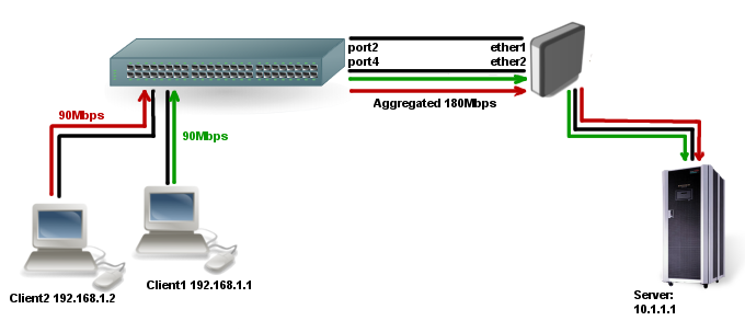
Example connects two ethernet interfaces on a router to the Edimax switch as a single, load balanced and fault tolerant link. More interfaces can be added to increase throughput and fault tolerance. Since frame ordering is mandatory on Ethernet links then any traffic between two devices always flows over the same physical link limiting the maximum speed to that of one interface. The transmit algorithm attempts to use as much information as it can to distinguish different traffic flows and balance across the available interfaces.
Router R1 configuration:
/inteface bonding add slaves=ether1,ether2 mode=802.3ad lacp-rate=30secs link-monitoring=mii \
  transmit-hash-policy=layer-2-and-3
Configuration on a switch:
                  Intelligent Switch : Trunk Configuration
                  ==================
 01 02 03 04 05 06 07 08 09 10 11 12 13 14 15 16 17 18 19 20 21 22 23 24 M1 M2
1 -  v  -  v  -  -  -  -  -  -  -  -  -  -  -  -  -  -  -  -  -  -  -  -  -  -
2 -  -  -  -  -  -  -  -  -  -  -  -  -  -  -  -  -  -  -  -  -  -  -  -  -  -
3 -  -  -  -  -  -  -  -  -  -  -  -  -  -  -  -  -  -  -  -  -  -  -  -  -  -
4 -  -  -  -  -  -  -  -  -  -  -  -  -  -  -  -  -  -  -  -  -  -  -  -  -  -
5 -  -  -  -  -  -  -  -  -  -  -  -  -  -  -  -  -  -  -  -  -  -  -  -  -  -
6 -  -  -  -  -  -  -  -  -  -  -  -  -  -  -  -  -  -  -  -  -  -  -  -  -  -
7 -  -  -  -  -  -  -  -  -  -  -  -  -  -  -  -  -  -  -  -  -  -  -  -  -  -

TRK1   LACP
TRK2   Disable
TRK3   Disable
TRK4   Disable
TRK5   Disable
TRK6   Disable
TRK7   Disable
Notice that LACP is enabled on first trunk group (TRK1) and switch ports on first trunk group are bound with ‘v’ flag. In our case port 2 and port4 will run LACP.
Verify if LACP is working:
On the switch we should first verify if LACP protocol is enabled and running:
                  Intelligent Switch : LACP Port State Active Configuration
                  ==================


     Port         State Activity             Port         State Activity
     ---------------------------             ---------------------------
     2            Active
     4            Active
After that we can ensure that LACP negotiated with our router. If you don’t see both ports on the list then something is wrong and LACP is not going to work.
                  Intelligent Switch : LACP Group Status
                  ==================


                                Group
                [Actor]                      [Partner]

   Priority:    1                            65535

   MAC     :    000E2E2206A9                 000C42409426

   Port_No   Key     Priority   Active       Port_No   Key     Priority
   2         513     1          selected     1         9       255
   4         513     1          selected     2         9       255
After we verified that switch successfully negotiated LACP with our router, we can start traffic from Client1 and Client2 to the Server and check how traffic is evenly forwarded through both bonding slaves:
[admin@test-host] /interface> monitor-traffic ether1,ether2,bonding1
    rx-packets-per-second: 8158     8120     16278
      rx-drops-per-second: 0        0        0
     rx-errors-per-second: 0        0        0
       rx-bits-per-second: 98.8Mbps 98.2Mbps 197.0Mbps
    tx-packets-per-second: 4833     4560     9394
      tx-drops-per-second: 0        0        0
     tx-errors-per-second: 0        0        0
       tx-bits-per-second: 2.7Mbps  3.0Mbps  5.8Mbps
![]()
Note: On some switches you need to set correct link aggregation protocol, to make balancing work in both directions
balance-rr
If this mode is set, packets are transmitted in sequential order from the first available slave to the last.
Balance-rr is the only mode that will send packets across multiple interfaces that belong to the same TCP/IP connection.
When utilizing multiple sending and multiple receiving links, packets are often received out of order, which result in segment retransmission, for other protocols such as UDP it is not a problem if client software can tolerate out-of-order packets.
If switch is used to aggregate links together, then appropriate switch port configuration is required, however many switches do not support balance-rr.
Quick setup guide demonstrates use of the balance-rr bonding mode. As you can see, it is quite simple to set up. Balance-rr is also useful for bonding several wireless links, however it requires equal bandwidth for all bonded links. If bandwidth of one bonded link drops, then total bandwidth of bond will be equal to the bandwidth of the slowest bonded link.
active-backup
This mode uses only one active slave to transmit packets. The additional slave only becomes active if the primary slave fails. The MAC address of the bonding interface is presented onto the active port to avoid confusing the switch.
Active-backup is the best choice in high availability setups with multiple switches that are interconnected.
![]()
Note: ARP monitoring in this mode will not work correctly if both routers are directly connected. In such setups mii monitoring must be used or a switch should be put between routers.
balance-xor
This mode balances outgoing traffic across the active ports based on the hashed protocol header information and accepts incoming traffic from any active port. Mode is very similar to LACP except that it is not standardized and works with layer-3-and-4 hash policy.
broadcast
When ports are configured with broadcast mode, all slave ports transmit the same packets to the destination to provide fault tolerance. This mode does not provide load balancing.
balance-tlb
This mode balances outgoing traffic by peer.
Each link can be a different speed and duplex mode and no specific switch configuration is required as for the other modes.
Downside of this mode is that only MII link monitoring is supported (ARP link monitoring is ignored when configured) and incoming traffic is not balanced. Incoming traffic will use the link that is configured as «primary».
Configuration example
Lets assume than router has two links — ether1 max bandwidth is 10Mbps and ether2 max bandwidth is 5Mbps.
First link has more bandwidth so we set it as primary link
/interface bonding add mode=balance-tlb slaves=ether1,ether2 primary=ether1
No additional configuration is required for the switch.
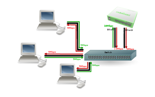
Image above illustrates how balance-tlb mode works. As you can see router can communicate to all the clients connected to the switch with a total bandwidth of both links (15Mbps). But as you already know, balance-tlb is not balancing incoming traffic. In our example clients can communicate to router with total bandwidth of primary link which is 10Mbps in our configuration.
balance-alb
Mode is basically the same as balance-tlb but incoming IPv4 traffic is also balanced. Only MII link monitoring is supported (ARP link monitoring is ignored when configured), additional downside of this mode is that it requires device driver capability to change MAC address. Most of the cheap cards do not support this mode.
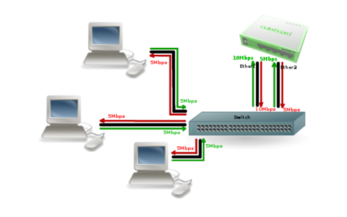
Image above illustrates how balance-alb mode works. Compared to balance-tlb mode, traffic from clients can also use the secondary link to communicate with the router.
Property Description
| Property | Description |
|---|---|
| arp (disabled | enabled | proxy-arp | reply-only; Default: enabled) | Address Resolution Protocol for the interface.
|
| arp-interval (time; Default: 00:00:00.100) | Time in milliseconds which defines how often to monitor ARP requests |
| arp-ip-targets (IP address; Default: ) | IP target address which will be monitored if link-monitoring is set to arp. You can specify multiple IP addresses, separated by comma |
| comment (string; Default: ) | Short description of the interface |
| disabled (yes | no; Default: no) | Changes whether the bonding interface is disabled |
| down-delay (time; Default: 00:00:00) | If a link failure has been detected, bonding interface is disabled for down-delay time. Value should be a multiple of mii-interval, otherwise it will be rounded down to the nearest value. |
| forced-mac-address (MAC address; Default: none) | By default, bonding interface will use MAC address of the first selected slave interface. This property allows to configure static MAC address for the bond interface (all zeros, broadcast or multicast addresses will not apply). RouterOS will automatically change the MAC address for slave interfaces and it will be visible in /interface ethernet configuration export |
| lacp-rate (1sec | 30secs; Default: 30secs) | Link Aggregation Control Protocol rate specifies how often to exchange with LACPDUs between bonding peer. Used to determine whether link is up or other changes have occurred in the network. LACP tries to adapt to these changes providing failover. |
| link-monitoring (arp | mii | none; Default: mii) | Method to use for monitoring the link (whether it is up or down)
Note: some bonding modes require specific link monitoring to work properly. |
| min-links (integer: 0..4294967295; Default: 0) | How many active slave links needed for bonding to become active |
| mii-interval (time; Default: 00:00:00.100) | How often to monitor the link for failures (parameter used only if link-monitoring is mii) |
| mode (802.3ad | active-backup | balance-alb | balance-rr | balance-tlb | balance-xor | broadcast; Default: balance-rr) | Specifies one of the bonding policies
|
| mtu (integer; Default: 1500) | Maximum Transmit Unit in bytes. Must be smaller or equal to the smallest L2MTU value of a bonding slave. |
| name (string; Default: ) | Name of the bonding interface |
| primary (string; Default: ) | Controls the primary interface between active slave ports, works only for active-backup, balance-tlb and balance-alb modes. For active-backup mode, it controls which running interface is supposed to send and receive the traffic. For balance-tlb mode, it controls which running interface is supposed to receive all the traffic, but for balance-alb mode, it controls which interface is supposed to receive the unbalanced traffic (the non-IPv4 traffic). When none of the interfaces are selected as primary, device will automatically select the interface that is configured as the first one. |
| slaves (string; Default: none) | At least two ethernet-like interfaces separated by a comma, which will be used for bonding |
| up-delay (time; Default: 00:00:00) | If a link has been brought up, bonding interface is disabled for up-delay time and after this time it is enabled. Value should be a multiple of mii-interval, otherwise it will be rounded down to the nearest value. |
| transmit-hash-policy (layer-2 | layer-2-and-3 | layer-3-and-4; Default: layer-2) | Selects the transmit hash policy to use for slave selection in balance-xor and 802.3ad modes
|
Notes
The rate at which link failure detection and failover takes place can depend on the network adapters used. On Intel cards, for example, failover takes place in less than a second after link loss, while on some other cards, it may require up to 20 seconds. Also, active load balancing (mode=balance-alb) does not work on some cheap cards.
L2 MTU of a bonding interface is determined by the lowest L2MTU value among its slave interfaces.
See also
- Bonding presentation at the MUM
- Bonding Examples
[ Top | Back to Content ]

Купить FS коммутаторы для предприятий
Агрегация каналов-это подход к объединению нескольких отдельных каналов (Ethernet) в один логический канал. Вместе с ним часто появляются два термина, то есть LAG и LACP. Они вас смутили? Давайте теперь немного подробнее рассмотрим эти термины.
Не стесняйтесь забегать вперед, если вы уже позаботились о некоторых деталях.
1. Что такое LAG и как оно работает?
2. Что такое LACP и как он работает?
3. LAG vs LACP: в чем разница?
4.Можно ли включить агрегирование каналов?
5. Как настроить коммутатор агрегации каналов?
6. Сетевые коммутаторы, поддерживающие LAG
Что такое LAG и как это работает?
LAG (Link Aggregation Group) — это реальный метод или пример для агрегации каналов. Группа агрегации каналов формируется, когда мы подключаем несколько портов параллельно между двумя коммутаторами и настраиваем их как LAG. LAG создает несколько каналов между двумя коммутаторами, что увеличивает пропускную способность.
Кроме того, он обеспечивает резервирование на уровне канала при отказе сети и балансировке нагрузки трафика. Даже если одна связь выйдет из строя, остальные связи между двумя коммутаторами все равно будут работать. Они также принимают на себя тот трафик, который должен проходить через вышедшего из строя, поэтому пакет данных не будет потерян.
Что такое LACP (протокол управления агрегацией каналов) и как он работает?
LACP — это подкомпонент стандарта IEEE 802.3ad (Link Aggregation).Стандарт предписывает, что LACP может быть методом объединения нескольких физических каналов между сетевыми устройствами в один логический канал.
В результате, каналы, поддерживающие протокол LACP, могут увеличить логическую полосу пропускания и надежность сети без изменения какой-либо сетевой инфраструктуры.
Более того, даже если одна ссылка выходит из строя, в режиме LACP другие доступные члены ссылки в той же группе LACP будут балансировать нагрузку.

В момент, когда LACP включен между двумя коммутаторами, они будут отправлять LACPDU (блоки данных LACP) друг другу. После получения друг от друга LACPDU два коммутатора будут определять, у какой стороны системный приоритет выше.
Затем они будут вести переговоры друг с другом, чтобы выбрать того, кто выше, чтобы быть Актером, а тот, кто ниже, — Партнером. Если два коммутатора имеют одинаковый системный приоритет, коммутатор с меньшим значением MAC-адреса будет Актером.

После выбора Субъекта два коммутатора будут выбирать активные порты на основе приоритетов портов порта Субъекта. Однако, если порты Субъекта имеют одинаковые приоритеты, порты с меньшими номерами портов будут выбраны в качестве активных портов.
После выбора соответствующих портов двух коммутаторов устанавливается порт-канал (группа LACP). Тогда активные ссылки загрузят данные баланса для связи.
LAG vs LACP: в чем разница?
LAG (link aggregation group) относится к исходной технологии для реализации объединения каналов и балансировки нагрузки без участия какого-либо протокола. Он также называется ручным режимом из-за его рабочего процесса — пользователям необходимо вручную создать порт-канал и добавить интерфейсы-элементы к этому порту-каналу.
После того, как каналы агрегации установлены, все эти ссылки становятся активными ссылками для пересылки пакетов данных. Если одна активная ссылка не работает, остальные оставшиеся активные ссылки будут балансировать нагрузку на трафик. Однако этот режим может обнаруживать только разъединения входящих в него каналов, но не может обнаруживать другие сбои, такие как сбои канального уровня и неправильные соединения каналов.
LACP — это протокол для автоматической настройки и поддержки LAG. В режиме LACP порт-канал создается на основе LACP. LACP предоставляет стандартный механизм согласования для коммутационного устройства, так что коммутационное устройство может автоматически формировать и запускать агрегированный канал в соответствии с его конфигурацией. После того, как агрегированный канал сформирован, LACP отвечает за поддержание статуса канала.
Когда условие агрегирования ссылок изменяется, LACP корректирует или удаляет агрегированный канал. Если одна активная ссылка выходит из строя, система выбирает ссылку среди резервных ссылок в качестве активной ссылки. Таким образом, количество ссылок, участвующих в пересылке данных, остается неизменным. Кроме того, этот режим не только обнаруживает разъединения своих звеньев, но и другие сбои, такие как сбои канального уровня и неправильные соединения каналов.
Должен ли я включать агрегацию каналов?
Если у вас есть коммутатор с большим количеством портов Gigabit Ethernet, вы можете подключить их все к другому устройству, у которого также есть несколько портов, и сбалансировать трафик между этими каналами для повышения производительности.
Другой важной причиной использования агрегации каналов является обеспечение быстрого и прозрачного восстановления в случае отказа одного из отдельных каналов.
Если вы очень заботитесь о надежности и доступности сети, было бы лучше включить агрегацию каналов на ваших устройствах.
Как настроить коммутатор агрегации каналов?
Коммутатор агрегации каналов или коммутатор LACP, см. Установку или настройку коммутатора для достижения технологии агрегации каналов. Коммутатор агрегации каналов может быть любым коммутатором, например Gigabit Ethernet коммутатор или 10 Gigabit коммутатор, который поддерживает LACP. Как правило, существует шесть шагов для настройки коммутаторов агрегации каналов:
Шаг 1. Добавьте интерфейсы участников в группу каналов.
Шаг 2: Установите приоритет системы LACP и определите Субъекта, чтобы Партнер выбирал активные интерфейсы на основе приоритета интерфейса Субъекта.
Шаг 3: Установите верхний порог количества активных интерфейсов для повышения надежности. (Этот шаг необязательно применяется в командах динамической конфигурации CLI.)
Шаг 4: Установите приоритеты интерфейса LACP и определите активные интерфейсы, чтобы интерфейсы с более высоким приоритетом выбирались в качестве активных интерфейсов. (Этот шаг необязательно применяется в командах динамической конфигурации CLI.)
Шаг 5: Создайте сети VLAN и добавьте интерфейсы к этим VLAN. (Этот шаг необязательно применяется в командах динамической конфигурации CLI.)
Шаг 6: Проверьте конфигурацию LACP.
Коммутаторы поддерживающие LAG
Если вы ищете хорошие сетевые коммутаторы, поддерживающие LACP, вот три самых продаваемых коммутатора от FS, глобальной высокотехнологичной компании, предоставляющей решения и услуги для высокоскоростных сетей связи.
| S3900-24T4S | S5850-48S6Q | S5860-20SQ | |
|---|---|---|---|
| Уровень управления | Layer 2+ | Layer 3 | Layer 3 |
| Комбинация портов | 24 x 1G, 4 x 10G SFP+ | 48 x 10G SFP+, 6 x 40G QSFP+ | 20 x 10G SFP+, 4 x 25G SFP28, 2 x 40G QSFP+ |
| Ключевая особенность | VLAN, QoS, IGMP Snooping, Link Aggregation, IPv6,L3 статическая маршрутизация | VLAN, QoS, IGMP Snooping, Link Aggregation, статическая маршрутизация, RIP, OSPF, IPv6 поддержка, BGP/ISIS, MLAG | QoS, IGMP Snooping, Link Aggregation, IPv6, L3 статическая маршрутизация, RIP, OSPF, BGP/ISIS, стекируемый |
| Применения | SMB(<300 пользователей) | Предприятие (300-2500 пользователей) | Среднее & крупное предприятие (>2500 пользователей) |
Заключение
Вы получили представление об агрегирования каналов, LAG и LACP? Сможете ли вы использовать их с пользой и найти сетевой коммутатор, который вам подойдет? Агрегация каналов — это способ объединения нескольких отдельных (Ethernet) каналов, чтобы они могли работать как единое логическое соединение. Группа портов, объединенных вместе, называется группой агрегации каналов или LAG. Протокол активного мониторинга, который позволяет устройствам включать или удалять отдельные ссылки из LAG, называется протоколом управления агрегацией каналов (LACP).