Table Of Contents
Basic Router Configuration
Interface Port Labels
Viewing the Default Configuration
Information Needed for Configuration
Configuring Basic Parameters
Configure Global Parameters
Configure Fast Ethernet LAN Interfaces
Configure WAN Interfaces
Configure the Fast Ethernet WAN Interface
Configure the ATM WAN Interface
Configure the Wireless Interface
Configuring a Loopback Interface
Configuration Example
Verifying Your Configuration
Configuring Command-Line Access to the Router
Configuration Example
Configuring Static Routes
Configuration Example
Verifying Your Configuration
Configuring Dynamic Routes
Configuring RIP
Configuration Example
Verifying Your Configuration
Configuring Enhanced IGRP
Configuration Example
Verifying Your Configuration
Basic Router Configuration
This chapter provides procedures for configuring the basic parameters of your Cisco router, including global parameter settings, routing protocols, interfaces, and command-line access. It also describes the default configuration on startup.

Note ![]() Individual router models may not support every feature described throughout this guide. Features not supported by a particular router are indicated whenever possible.
Individual router models may not support every feature described throughout this guide. Features not supported by a particular router are indicated whenever possible.
This chapter contains the following sections:
•![]() Interface Port Labels
Interface Port Labels
•![]() Viewing the Default Configuration
Viewing the Default Configuration
•![]() Information Needed for Configuration
Information Needed for Configuration
•![]() Configuring Basic Parameters
Configuring Basic Parameters
•![]() Configuring Static Routes
Configuring Static Routes
•![]() Configuring Dynamic Routes
Configuring Dynamic Routes
•![]() Configuring Enhanced IGRP
Configuring Enhanced IGRP
Each section includes a configuration example and verification steps, as available.
For complete information on how to access global configuration mode, see the «Entering Global Configuration Mode» section in Appendix A, «Cisco IOS Basic Skills.» For more information on the commands used in the following tables, see the Cisco IOS Release 12.3 documentation set.
Interface Port Labels
Table 1-1 lists the interfaces supported for each router and their associated port labels on the equipment.
|
Router |
Interface |
Port Label |
|---|---|---|
|
Cisco 851 |
Fast Ethernet LAN |
LAN (top), FE0-FE3 (bottom) |
|
Fast Ethernet WAN |
WAN (top), FE4 (bottom) |
|
|
Wireless LAN |
(no label) |
|
|
Cisco 871 |
Fast Ethernet LAN |
FE0-FE3 |
|
Fast Ethernet WAN |
FE4 |
|
|
Wireless LAN |
LEFT, RIGHT/PRIMARY |
|
|
USB |
1-0 |
|
|
Cisco 857 |
Fast Ethernet LAN |
LAN (top), FE0-FE3 (bottom) |
|
ATM WAN |
ADSLoPOTS |
|
|
Wireless LAN |
(no label) |
|
|
Cisco 876 |
Fast Ethernet LAN |
LAN (top), FE0-FE3 (bottom) |
|
ATM WAN |
ADSLoISDN |
|
|
Wireless LAN |
LEFT, RIGHT/PRIMARY |
|
|
BRI |
ISDN S/T |
|
|
Cisco 877 |
Fast Ethernet LAN |
LAN (top), FE0-FE3 (bottom) |
|
ATM WAN |
ADSLoPOTS |
|
|
Wireless LAN |
LEFT, RIGHT/PRIMARY |
|
|
Cisco 878 |
Fast Ethernet LAN |
FE0-FE3 |
|
ATM WAN |
G.SHDSL |
|
|
Wireless LAN |
LEFT, RIGHT/PRIMARY |
|
|
BRI |
ISDN S/T |
Viewing the Default Configuration
When you first boot up your Cisco router, some basic configuration has already been performed. All of the LAN and WAN interfaces have been created, console and VTY ports are configured, and the inside interface for Network Address Translation has been assigned. Use the show running-config command to view the initial configuration, as shown in Example 1-1.
Example 1-1 Cisco 851 Default Configuration on Startup
Router# show running-config
Building configuration...
Current configuration : 1090 bytes
service timestamps debug datetime msec
service timestamps log datetime msec
no service password-encryption
no ftp-server write-enable
speed basic-1.0 basic-2.0 basic-5.5 6.0 9.0 basic-11.0 12.0 18.0 24.0 36.0 48.0
Information Needed for Configuration
You need to gather some or all of the following information, depending on your planned network scenario, prior to configuring your network
•![]() If you are setting up an Internet connection, gather the following information:
If you are setting up an Internet connection, gather the following information:
–![]() Point-to-Point Protocol (PPP) client name that is assigned as your login name
Point-to-Point Protocol (PPP) client name that is assigned as your login name
–![]() PPP authentication type: Challenge Handshake Authentication Protocol (CHAP) or Password Authentication Protocol (PAP)
PPP authentication type: Challenge Handshake Authentication Protocol (CHAP) or Password Authentication Protocol (PAP)
–![]() PPP password to access your Internet service provider (ISP) account
PPP password to access your Internet service provider (ISP) account
–![]() DNS server IP address and default gateways
DNS server IP address and default gateways
•![]() If you are setting up a connection to a corporate network, you and the network administrator must generate and share the following information for the WAN interfaces of the routers:
If you are setting up a connection to a corporate network, you and the network administrator must generate and share the following information for the WAN interfaces of the routers:
–![]() PPP authentication type: CHAP or PAP
PPP authentication type: CHAP or PAP
–![]() PPP client name to access the router
PPP client name to access the router
–![]() PPP password to access the router
PPP password to access the router
•![]() If you are setting up IP routing:
If you are setting up IP routing:
–![]() Generate the addressing scheme for your IP network.
Generate the addressing scheme for your IP network.
–![]() Determine the IP routing parameter information, including IP address, and ATM permanent virtual circuits (PVCs). These PVC parameters are typically virtual path identifier (VPI), virtual circuit identifier (VCI), and traffic shaping parameters.
Determine the IP routing parameter information, including IP address, and ATM permanent virtual circuits (PVCs). These PVC parameters are typically virtual path identifier (VPI), virtual circuit identifier (VCI), and traffic shaping parameters.
–![]() Determine the number of PVCs that your service provider has given you, along with their VPIs and VCIs.
Determine the number of PVCs that your service provider has given you, along with their VPIs and VCIs.
–![]() For each PVC determine the type of AAL5 encapsulation supported. It can be one of the following:
For each PVC determine the type of AAL5 encapsulation supported. It can be one of the following:
AAL5SNAP—This can be either routed RFC 1483 or bridged RFC 1483. For routed RFC 1483, the service provider must provide you with a static IP address. For bridged RFC 1483, you may use DHCP to obtain your IP address, or you may obtain a static IP address from your service provider.
AAL5MUX PPP—With this type of encapsulation, you need to determine the PPP-related configuration items.
•![]() If you plan to connect over an ADSL or G.SHDSL line:
If you plan to connect over an ADSL or G.SHDSL line:
–![]() Order the appropriate line from your public telephone service provider.
Order the appropriate line from your public telephone service provider.
For ADSL lines—Ensure that the ADSL signaling type is DMT (also called ANSI T1.413) or DMT Issue 2.
For G.SHDSL lines—Verify that the G.SHDSL line conforms to the ITU G.991.2 standard and supports Annex A (North America) or Annex B (Europe).
Once you have collected the appropriate information, you can perform a full configuration on your router, beginning with the tasks in the «Configuring Basic Parameters» section.
Configuring Basic Parameters
To configure the router, perform one or more of these tasks:
•![]() Configure Global Parameters
Configure Global Parameters
•![]() Configure Fast Ethernet LAN Interfaces
Configure Fast Ethernet LAN Interfaces
•![]() Configure WAN Interfaces
Configure WAN Interfaces
•![]() Configuring a Loopback Interface
Configuring a Loopback Interface
•![]() Configuring Command-Line Access to the Router
Configuring Command-Line Access to the Router
A configuration example is presented with each task to show the network configuration following completion of that task.
Configure Global Parameters
Perform these steps to configure selected global parameters for your router:
|
Command |
Purpose |
|
|---|---|---|
|
Step 1 |
configure terminal Example: Router> enable Router# configure terminal Router(config)# |
Enters global configuration mode, when using the console port. If you are connecting to the router using a remote terminal, use the following: telnet router name or address Login: login id Password: ********* Router> enable |
|
Step 2 |
hostname name Example: Router(config)# hostname Router Router(config)# |
Specifies the name for the router. |
|
Step 3 |
enable secret password Example: Router(config)# enable secret cr1ny5ho Router(config)# |
Specifies an encrypted password to prevent unauthorized access to the router. |
|
Step 4 |
no ip domain-lookup Example: Router(config)# no ip domain-lookup |
Disables the router from translating unfamiliar words (typos) into IP addresses. |
For complete information on the global parameter commands, see the Cisco IOS Release 12.3 documentation set.
Configure Fast Ethernet LAN Interfaces
The Fast Ethernet LAN interfaces on your router are automatically configured as part of the default VLAN and as such, they are not configured with individual addresses. Access is afforded through the VLAN. You may assign the interfaces to other VLANs if desired. For more information about creating VLANs, see Chapter 5 «Configuring a LAN with DHCP and VLANs.»
Configure WAN Interfaces
The Cisco 851 and Cisco 871 routers each have one Fast Ethernet interface for WAN connection. The Cisco 857, Cisco 877, and Cisco 878 routers each have one ATM interface for WAN connection.
Based on the router model you have, configure the WAN interface(s) using one of the following procedures:
•![]() Configure the Fast Ethernet WAN Interface
Configure the Fast Ethernet WAN Interface
•![]() Configure the ATM WAN Interface
Configure the ATM WAN Interface
Configure the Fast Ethernet WAN Interface
This procedure applies only to the Cisco 851 and Cisco 871 router models. Perform these steps to configure the Fast Ethernet interface, beginning in global configuration mode:
|
Command |
Purpose |
|
|---|---|---|
|
Step 1 |
interface type number Example: Router(config)# interface fastethernet 4
Router(config-int)# |
Enters the configuration mode for a Fast Ethernet WAN interface on the router. |
|
Step 2 |
ip address ip-address mask Example: Router(config-int)# ip address 192.168.12.2
255.255.255.0
Router(config-int)# |
Sets the IP address and subnet mask for the specified Fast Ethernet interface. |
|
Step 3 |
no shutdown Example: Router(config-int)# no shutdown
Router(config-int)# |
Enables the Ethernet interface, changing its state from administratively down to administratively up. |
|
Step 4 |
exit Example: Router(config-int)# exit
Router(config)# |
Exits configuration mode for the Fast Ethernet interface and returns to global configuration mode. |
Configure the ATM WAN Interface
This procedure applies only to the Cisco 857, Cisco 876, Cisco 877 and Cisco 878 models.
Perform these steps to configure the ATM interface, beginning in global configuration mode:
|
Command |
Purpose |
|
|---|---|---|
|
Step 1 |
For the Cisco 878 model only:
controller dsl 0 Example: Router(config)# controller dsl 0
Router(config-controller)# mode atm
Router(config-controller)# exit Router(config)# |
For routers using the G.SHDSL signaling, perform these commands. Ignore this step for routers using ADSL signaling. |
|
Step 2 |
interface type number Example: Router(config)# interface atm0
Router(config-int)# |
Identifies and enters the configuration mode for an ATM interface. |
|
Step 3 |
ip address ip-address mask Example: Router(config-int)# ip address 10.10.10.100
255.255.255.0
Router(config-int)# |
Sets the IP address and subnet mask for the ATM interface. |
|
Step 4 |
no shutdown Example: Router(config-int)# no shutdown
Router(config-int)# |
Enables the ATM 0 interface. |
|
Step 5 |
exit Example: Router(config-int)# exit
Router(config)# |
Exits configuration mode for the ATM interface and returns to global configuration mode. |
Configure the Wireless Interface
The wireless interface enables connection to the router through a wireless LAN connection. For more information about configuring a wireless connection, see Chapter 9 «Configuring a Wireless LAN Connection,» and the Cisco Access Router Wireless Configuration Guide.
Configuring a Loopback Interface
The loopback interface acts as a placeholder for the static IP address and provides default routing information.
For complete information on the loopback commands, see the Cisco IOS Release 12.3 documentation set.
Perform these steps to configure a loopback interface:
|
Command |
Purpose |
|
|---|---|---|
|
Step 1 |
interface type number Example: Router(config)# interface Loopback 0
Router(config-int)# |
Enters configuration mode for the loopback interface. |
|
Step 2 |
ip address ip-address mask Example: Router(config-int)# ip address 10.108.1.1
255.255.255.0
Router(config-int)# |
Sets the IP address and subnet mask for the loopback interface. |
|
Step 3 |
exit Example: Router(config-int)# exit
Router(config)# |
Exits configuration mode for the loopback interface and returns to global configuration mode. |
Configuration Example
The loopback interface in this sample configuration is used to support Network Address Translation (NAT) on the virtual-template interface. This configuration example shows the loopback interface configured on the Fast Ethernet interface with an IP address of 10.10.10.100/24, which acts as a static IP address. The loopback interface points back to virtual-template1, which has a negotiated IP address.
ip address 10.10.10.100 255.255.255.0 (static IP address)
interface Virtual-Template1
Verifying Your Configuration
To verify that you have properly configured the loopback interface, enter the show interface loopback command. You should see verification output similar to the following example.
Router# show interface loopback 0
Loopback0 is up, line protocol is up
Internet address is 10.10.10.100/24
MTU 1514 bytes, BW 8000000 Kbit, DLY 5000 usec,
reliability 255/255, txload 1/255, rxload 1/255
Encapsulation LOOPBACK, loopback not set
Last input never, output never, output hang never
Last clearing of "show interface" counters never
Output queue 0/0, 0 drops; input queue 0/75, 0 drops
5 minute input rate 0 bits/sec, 0 packets/sec
5 minute output rate 0 bits/sec, 0 packets/sec
0 packets input, 0 bytes, 0 no buffer
Received 0 broadcasts, 0 runts, 0 giants, 0 throttles
0 input errors, 0 CRC, 0 frame, 0 overrun, 0 ignored, 0 abort
0 packets output, 0 bytes, 0 underruns
0 output errors, 0 collisions, 0 interface resets
0 output buffer failures, 0 output buffers swapped out
Another way to verify the loopback interface is to ping it:
Router# ping 10.10.10.100
Type escape sequence to abort.
Sending 5, 100-byte ICMP Echos to 10.10.10.100, timeout is 2 seconds:
Success rate is 100 percent (5/5), round-trip min/avg/max = 1/2/4 ms
Configuring Command-Line Access to the Router
Perform these steps to configure parameters to control access to the router, beginning in global configuration mode.
|
Command |
Purpose |
|
|---|---|---|
|
Step 1 |
line [aux | console | tty | vty] line-number Example: Router(config)# line console 0
Router(config)# |
Enters line configuration mode, and specifies the type of line. This example specifies a console terminal for access. |
|
Step 2 |
password password Example: Router(config)# password 5dr4Hepw3
Router(config)# |
Specifies a unique password for the console terminal line. |
|
Step 3 |
login Example: Router(config)# login
Router(config)# |
Enables password checking at terminal session login. |
|
Step 4 |
exec-timeout minutes [seconds] Example: Router(config)# exec-timeout 5 30
Router(config)# |
Sets the interval that the EXEC command interpreter waits until user input is detected. The default is 10 minutes. Optionally, add seconds to the interval value. This example shows a timeout of 5 minutes and 30 seconds. Entering a timeout of 0 0 specifies never to time out. |
|
Step 5 |
line [aux | console | tty | vty] line-number Example: Router(config)# line vty 0 4
Router(config)# |
Specifies a virtual terminal for remote console access. |
|
Step 6 |
password password Example: Router(config)# password aldf2ad1
Router(config)# |
Specifies a unique password for the virtual terminal line. |
|
Step 7 |
login Example: Router(config)# login
Router(config)# |
Enables password checking at the virtual terminal session login. |
|
Step 8 |
end Example: Router(config)# end
Router# |
Exits line configuration mode, and returns to privileged EXEC mode. |
For complete information about the command line commands, see the Cisco IOS Release 12.3 documentation set.
Configuration Example
The following configuration shows the command-line access commands.
You do not need to input the commands marked «default.» These commands appear automatically in the configuration file generated when you use the show running-config command.
transport input none (default)
Configuring Static Routes
Static routes provide fixed routing paths through the network. They are manually configured on the router. If the network topology changes, the static route must be updated with a new route. Static routes are private routes unless they are redistributed by a routing protocol. Configuring static routes on the Cisco 850 and Cisco 870 series routers is optional.
Perform these steps to configure static routes, beginning in global configuration mode:
|
Command |
Purpose |
|
|---|---|---|
|
Step 1 |
ip route prefix mask {ip-address | interface-type interface-number [ip-address]} Example: Router(config)# ip route 192.168.1.0
255.255.0.0 10.10.10.2
Router(config)# |
Specifies the static route for the IP packets. For details about this command and additional parameters that can be set, see the Cisco IOS IP Command Reference, Volume 2 of 4: Routing Protocols. |
|
Step 2 |
end Example: Router(config)# end
Router# |
Exits router configuration mode, and enters privileged EXEC mode. |
For complete information on the static routing commands, see the Cisco IOS Release 12.3 documentation set. For more general information on static routing, see «Concepts.»
Configuration Example
In the following configuration example, the static route sends out all IP packets with a destination IP address of 192.168.1.0 and a subnet mask of 255.255.255.0 on the Fast Ethernet interface to another device with an IP address of 10.10.10.2. Specifically, the packets are sent to the configured PVC.
You do not need to enter the commands marked «(default).» These commands appear automatically in the configuration file generated when you use the show running-config command.
ip route 192.168.1.0 255.255.255.0 10.10.10.2!
Verifying Your Configuration
To verify that you have properly configured static routing, enter the show ip route command and look for static routes signified by the «S.»
You should see verification output similar to the following example.
Codes: C - connected, S - static, R - RIP, M - mobile, B - BGP
D - EIGRP, EX - EIGRP external, O - OSPF, IA - OSPF inter area
N1 - OSPF NSSA external type 1, N2 - OSPF NSSA external type 2
E1 - OSPF external type 1, E2 - OSPF external type 2
i - IS-IS, su - IS-IS summary, L1 - IS-IS level-1, L2 - IS-IS level-2
ia - IS-IS inter area, * - candidate default, U - per-user static route
o - ODR, P - periodic downloaded static route
Gateway of last resort is not set
10.0.0.0/24 is subnetted, 1 subnets
C 10.108.1.0 is directly connected, Loopback0
S* 0.0.0.0/0 is directly connected, FastEthernet0
Configuring Dynamic Routes
In dynamic routing, the network protocol adjusts the path automatically, based on network traffic or topology. Changes in dynamic routes are shared with other routers in the network.
The Cisco routers can use IP routing protocols, such as Routing Information Protocol (RIP) or Enhanced Interior Gateway Routing Protocol (EIGRP), to learn routes dynamically. You can configure either of these routing protocols on your router.
Configuring RIP
Perform these steps to configure the RIP routing protocol on the router, beginning in global configuration mode:
|
Command |
Task |
|
|---|---|---|
|
Step 1 |
router rip Example: Router> configure terminal
Router(config)# router rip
Router(config-router)# |
Enters router configuration mode, and enables RIP on the router. |
|
Step 2 |
version {1 | 2} Example: Router(config-router)# version 2
Router(config-router)# |
Specifies use of RIP version 1 or 2. |
|
Step 3 |
network ip-address Example: Router(config-router)# network 192.168.1.1
Router(config-router)# network 10.10.7.1
Router(config-router)# |
Specifies a list of networks on which RIP is to be applied, using the address of the network of directly connected networks. |
|
Step 4 |
no auto-summary Example: Router(config-router)# no auto-summary
Router(config-router)# |
Disables automatic summarization of subnet routes into network-level routes. This allows subprefix routing information to pass across classful network boundaries. |
|
Step 5 |
end Example: Router(config-router)# end
Router# |
Exits router configuration mode, and enters privileged EXEC mode. |
For complete information on the dynamic routing commands, see the Cisco IOS Release 12.3 documentation set. For more general information on RIP, see «Concepts.»
Configuration Example
The following configuration example shows RIP version 2 enabled in IP network 10.0.0.0 and 192.168.1.0.
Execute the show running-config command from privileged EXEC mode to see this configuration.
Verifying Your Configuration
To verify that you have properly configured RIP, enter the show ip route command and look for RIP routes signified by «R.» You should see a verification output like the example shown below.
Codes: C - connected, S - static, R - RIP, M - mobile, B - BGP
D - EIGRP, EX - EIGRP external, O - OSPF, IA - OSPF inter area
N1 - OSPF NSSA external type 1, N2 - OSPF NSSA external type 2
E1 - OSPF external type 1, E2 - OSPF external type 2
i - IS-IS, su - IS-IS summary, L1 - IS-IS level-1, L2 - IS-IS level-2
ia - IS-IS inter area, * - candidate default, U - per-user static route
o - ODR, P - periodic downloaded static route
Gateway of last resort is not set
10.0.0.0/24 is subnetted, 1 subnets
C 10.108.1.0 is directly connected, Loopback0
R 3.0.0.0/8 [120/1] via 2.2.2.1, 00:00:02, Ethernet0/0
Configuring Enhanced IGRP
Perform these steps to configure Enhanced IGRP (EIGRP), beginning in global configuration mode:
|
Command |
Purpose |
|
|---|---|---|
|
Step 1 |
router eigrp as-number Example: Router(config)# router eigrp 109
Router(config)# |
Enters router configuration mode, and enables EIGRP on the router. The autonomous-system number identifies the route to other EIGRP routers and is used to tag the EIGRP information. |
|
Step 2 |
network ip-address Example: Router(config)# network 192.145.1.0
Router(config)# network 10.10.12.115
Router(config)# |
Specifies a list of networks on which EIGRP is to be applied, using the IP address of the network of directly connected networks. |
|
Step 3 |
end Example: Router(config-router)# end
Router# |
Exits router configuration mode, and enters privileged EXEC mode. |
For complete information on the IP EIGRP commands, see the Cisco IOS Release 12.3 documentation set. For more general information on EIGRP concepts, see «Concepts.»
Configuration Example
The following configuration example shows the EIGRP routing protocol enabled in IP networks 192.145.1.0 and 10.10.12.115. The EIGRP autonomous system number is 109.
Execute the show running-config command from privileged EXEC mode to see this configuration.
Verifying Your Configuration
To verify that you have properly configured IP EIGRP, enter the show ip route command, and look for EIGRP routes indicated by «D.» You should see verification output similar to the following example.
Codes: C - connected, S - static, R - RIP, M - mobile, B - BGP
D - EIGRP, EX - EIGRP external, O - OSPF, IA - OSPF inter area
N1 - OSPF NSSA external type 1, N2 - OSPF NSSA external type 2
E1 - OSPF external type 1, E2 - OSPF external type 2
i - IS-IS, su - IS-IS summary, L1 - IS-IS level-1, L2 - IS-IS level-2
ia - IS-IS inter area, * - candidate default, U - per-user static route
o - ODR, P - periodic downloaded static route
Gateway of last resort is not set
10.0.0.0/24 is subnetted, 1 subnets
C 10.108.1.0 is directly connected, Loopback0
D 3.0.0.0/8 [90/409600] via 2.2.2.1, 00:00:02, Ethernet0/0
02.08.2021
Содержание статьи:
- Команды маршрутизатора для начальной настройки
- Базовые команды для настройки маршрутизатора Cisco
- Команды маршрутизатора Cisco для настройки интерфейса
- Команды маршрутизатора Cisco для работы с интерфейсами – пример настройки
- Проверка настроек портов
- Работа с таблицей маршрутизации роутера
- Взаимодействие с флэш-памятью и NVRAM
Базовая настройка работы маршрутизатора начинается с осуществления действий, выполняемых в режиме настройки роутера.
Ниже мы разберем базовые команды для настройки маршрутизатора компании Cisco, а также примеры их применения.
Стоит отметить, что роутеры этого бренда имеют много отличительных особенностей, касающихся настройки,
однако их популярность требует от сетевого администратора и других специалистов владеть перечнем команд, требующихся наиболее часто.

Команды маршрутизатора для начальной настройки
Чтобы перейти в режим конфигурирования устройства, следует прописать команду configure terminal. При этом нужно задать такие параметры:
- Имя роутера:
Router(config)# hostname - Пароль для входа в режим администрирования:
Router(config)# enable secret password - Пароль для консольного входа:
Router(config)# line console 0 Router(config-line)# password password Router(config-line)# login -
Код удаленного доступа (Telnet/SSH):
Router(config-line)# line vty 0 4 Router(config-line)# password password Router(config-line)# login Router(config-line)# transport input {ssh | telnet} -
Шифрование паролей:
Router(config-line)# exit Router(config)# service password-encryption - Предупреждение о несанкционированном подключении – выводится в виде баннера при активации подключения к маршрутизатору:
Router(config)# banner motd delimiter message delimiter -
Сохранение:
Router(config)# end
Router# copy running-config startup-config
Базовые команды для настройки маршрутизатора Cisco
Разберем пример, в котором покажем команды для настройки маршрутизатора Cisco. Возьмем роутер, обозначенный R1 и проведем его первичную настройку.
Начнем с команд:
   Router> enable
Router# configure terminal
Enter configuration commands, one per line.
End with CNTL/Z.
Router(config)# hostname R1
R1(config)#
В силу того, что привилегированный режим позволяет управлять настройками роутера на правах администратора, доступ к нему должен быть надежно защищен.
Поэтому шифрованию следует уделять особое внимание.
С этой целью можно применить следующую цепочку команд:
    R1(config)# enable secret class
    R1(config)#
    R1(config)# line console 0
    R1(config-line)# password cisco
    R1(config-line)# login
    R1(config-line)# exit
    R1(config)#
    R1(config)# line vty 0 4
    R1(config-line)# password cisco
    R1(config-line)# login
    R1(config-line)# transport input ssh telnet
    R1(config-line)# exit
    R1(config)#
    R1(config)# service password-encryption
    R1(config)#
Таким образом, мы защитим режимы пользователя и администратора, активируем Telnet/SSH и надежно защитим все пароли шифрованием.
Следующим шагом будет настройка баннера, предупреждающего о юридической ответственности за несанкционированный вход.
Баннер имеет название Message of the Day и говорит о том, что лишь авторизованные лица имеют доступ к маршрутизатору. Введем следующие команды:
    R1(config)# banner motd #
Enter TEXT message. End with a new line and the #
***********************************************
WARNING: Unauthorized access is prohibited!
***********************************************
#
R1(config)#
Команды маршрутизатора Cisco для настройки интерфейса
После первичной настройки следует продолжить конфигурировать роутер.
Слеующий этап – настройка интерфейсов, которая выполняется для предоставления доступа к устройству для других пользователей.
Маршрутизаторы Cisco оснащаются различными интерфейсами. Например, в модели ISR 4321 два интерфейса:
- GigabitEthernet 0/0/0;
- GigabitEthernet 0/0/1.
Настройка интерфейсов проводится посредством ввода команд:
    Router(config)# interface type-and-number
Router(config-if)# description description-text
Router(config-if)# ip address ipv4-address subnet-mask
Router(config-if)# ipv6 address ipv6-address/prefix-length
Router(config-if)# no shutdown
После активации порта вы увидите уведомление об этом в консольном окне.
Команда Description не является обязательной для активации интерфейса, но ею лучше не пренебрегать.
Текстовая длина данной команды равна 240 символам. Если речь идет о ликвидации неполадок в работе производственных сетей,
информация о типе сетевого подключения будет полезной. Это может быть, например, если необходимо подключить интерфейс к провайдеру.
Здесь необходимо будет ввести внешнее соединение и информацию о контакте.
Включение интерфейса (по аналогии включения питания) задается командой no shutdown. При подключении роутера к другому устройству появится физическая связь.
Также команда будет полезна в следующих ситуациях:
- работа в режиме конфигурации;
- диагностика либо настройка новых интерфейсов;
- проблемы, возникающие в отношении интерфейсов (в этом случае можно использовать shut или no shut).
Команды маршрутизатора Cisco для работы с интерфейсами – пример настройки
На роутере R1 активируем подключенные порты. Настройка портов будет проведена следующим образом:
  R1> enable
R1# configure terminal
Enter configuration commands, one per line.
End with CNTL/Z.
R1(config)# interface gigabitEthernet 0/0/0
R1(config-if)# description Link to LAN
R1(config-if)# ip address 192.168.10.1 255.255.255.0
R1(config-if)# ipv6 address 2001:db8:acad:10::1/64
R1(config-if)# no shutdown
R1(config-if)# exit
R1(config)#
*Aug 1 01:43:53.435: %LINK-3-UPDOWN: Interface GigabitEthernet0/0/0, changed state to down
*Aug 1 01:43:56.447: %LINK-3-UPDOWN: Interface GigabitEthernet0/0/0, changed state to up
*Aug 1 01:43:57.447: %LINEPROTO-5-UPDOWN: Line protocol on Interface GigabitEthernet0/0/0, changed state to up
R1(config)#
R1(config)#
R1(config)# interface gigabitEthernet 0/0/1
R1(config-if)# description Link to R2
R1(config-if)# ip address 209.165.200.225 255.255.255.252
R1(config-if)# ipv6 address 2001:db8:feed:224::1/64
R1(config-if)# no shutdown
R1(config-if)# exit
R1(config)#
*Aug 1 01:46:29.170: %LINK-3-UPDOWN: Interface GigabitEthernet0/0/1, changed state to down
*Aug 1 01:46:32.171: %LINK-3-UPDOWN: Interface GigabitEthernet0/0/1, changed state to up
*Aug 1 01:46:33.171: %LINEPROTO-5-UPDOWN: Line protocol on Interface GigabitEthernet0/0/1, changed state to up
R1(config)#
После этого мы получим мэсэнджи о том, что порты подключены.

Проверка настроек портов
Базовые и наиболее целевые команды маршрутизатора для проверок портов имеют следующий вид:
- show ip interface brief;
- show ipv6 interface brief.
Покажем на примере:
R1#  show ip interface brief
Interface              IP-Address  	OK? Method Status            	Protocol
GigabitEthernet0/0/0   192.168.10.1	YES manual up                	up
GigabitEthernet0/0/1   209.165.200.225 YES manual up                	up
Vlan1                  unassigned  	YES unset  administratively down down
R1#  show ipv6 interface brief
GigabitEthernet0/0/0   	[up/up]
	FE80::201:C9FF:FE89:4501
	2001:DB8:ACAD:10::1
GigabitEthernet0/0/1   	[up/up]
	FE80::201:C9FF:FE89:4502
	2001:DB8:FEED:224::1
Vlan1                      [administratively down/down]
	unassigned
R1#
Работа с таблицей маршрутизации роутера
Вызов таблицы маршрутизации выполняется посредством ввода команды: show ip route . Здесь будут отображены все сети, которые доступны данному маршрутизатору,
метрика и шлюза. Краткая запись команды выглядит, как sh ip ro . После команды могут быть также указываться определенные параметры,
например sh ip ro ospf – для просмотра соответствующей маршрутизации.
Очистка таблицы маршрутизации выполняется с помощью Clear up route , после чего указывается адрес сети (например, Clear up route 1.1.1.1 ).
Взаимодействие с флэш-памятью и NVRAM
Для роутеров Cisco актуальны три программы:
- ROM монитор для загрузки и отладки;
- Boot ROM;
- система во флэш – установленная самостоятельно.
Параметры записаны в NVRAM. Оперативная память предназначена для сохранности данных, при этом выполнение IOS идет из ROM.
При работе с IOS 9.1 важно знать, что пароль здесь задается командой enable password , но никак не enable secret .
Просмотр флэша выполняется с помощью команды show flash all . В командной строке выглядит это следующим образом:
    System flash directory:
File Length Name/status
     addr fcksum ccksum
1    3243752 igs-i-l.110-1
0x40 0xB5C4 0xB5C4
[3243816 bytes used, 950488 available, 4194304 total]
4096K bytes of processor board System flash (Read ONLY)
Chip Bank Code Size Name
1 1 89A2 1024KB INTEL 28F008SA
2 1 89A2 1024KB INTEL 28F008SA
3 1 89A2 1024KB INTEL 28F008SA
4 1 89A2 1024KB INTEL 28F008SA
Executing current image from System flash
Посмотреть записи флэш: show flash err . Копирование информации из флэш на tftp делаем с помощью copy flash tftp .
Здесь мы получим мэсэндж о том, что нужно ввести имя сервера, изначальное и результирующее имена файла (файл с правами 666).
Делаем копию настроек параметров на tftp: copy startup-config/running-config tftp
    Router#copy tftp.
Router#copy tftp
Router#copy tftp flash
**** NOTICE ****
Flash load helper v1.0
This process will accept the copy options and then terminate
the current system image to use the ROM based image for the copy.
Routing functionality will not be available during that time.
If you are logged in via telnet, this connection will terminate.
Users with console access can see the results of the copy operation.
---- ******** ----
[There are active users logged into the system]
Proceed? [confirm]y
System flash directory:
File Length Name/status
1 5010180 c2500-ras-113.6
[5010244 bytes used, 3378364 available, 8388608 total]
Address or name of remote host 172.16.150.2
Source file name? c2500-ras-113.6 name of file in flash
Destination file name [c2500-ras-113.6]y
Accessing file 'c2500-ras-113.6' on 172.16.150.2...
Проверка, записан ли файл на TFTP сервер.
Загрузка настроек с TFTP: copy tftp startup-config/running-config.
При копировании из TFTP во флэш (copy tftp flash ) важно, чтоб было достаточно свободной памяти.
Если выполнение IOS проводится из flash, то проводится новая загрузка. Затем сохраняем конфигурацию
copy run start . Для загрузки из ROM IOS в регистре конфигурации задается значение 0-0-0-1.
Показать регистр конфигурации: show version (в основном, это загрузочные настройки роутера: дата последней загрузки, версия IOS, название файла IOS,
модель маршрутизатора, объем памяти на flash и оперативной). Команду можно писать сокращенно sh ver .
Проверка контрольной суммы проводится вводом verify flash .
Еще раз выполнить файл конфигурации: configure memory .
Очистка конфигурации: erase startup .
Показать текущую/загрузочную конфигурацию: show run/start .
В NVRAM будут сохранены только несовпадающие со значением по умолчанию параметры. Значения по умолчанию могут отличаться для различных версий.
При неполадках удобно использовать сохраненный на TFTP и загруженный с него файл конфигурации, IOS.
Debug также представляет полезные команды для настройки маршрутизатора. Здесь вы сможете посмотреть подробные данные,
касающиеся конкретного протокола, службы, приложения. К примеру, debug ip route сообщит о появлении нового или удалении старого маршрута из роутера.
![[CCNA] Шпаргалка по командам Cisco](https://bookflow.ru/wp-content/uploads/2021/09/CCNA-SHpargalka-po-komandam-Cisco-696x458.jpeg "[CCNA] Шпаргалка по командам Cisco")
Содержание

[CCNA] Cisco Commands Cheat Sheet
Router Modes:
- Router>: User mode = Limited to basic monitoring commands
- Router#: Privileged mode (exec-level mode) = Provides access to all other router commands
- Router(config)#: global configuration mode = Commands that affect the entire system
- Router(config-if)#: interface mode = Commands that affect interfaces
- Router(config-subif)#: subinterface mode = Commands that affect subinterfaces
- Router(config-line)#: line mode = Commands that affect in lines modes (console, vty, aux…)
- Router(config-router)#: router configuration mode
Changing switch hostname:
|
1 |
|
Configuring passwords:
|
1 2 |
|
Securing console port:
|
1 2 3 |
|
Securing terminal lines:
|
1 2 3 |
|
Encrypting passwords:
|
1 |
|
Configuring banners:
|
1 2 3 4 5 |
|
Giving the switch an IP address:
|
1 2 3 |
|
Setting the default gateway:
|
1 |
|
Saving configuration:
|
1 2 3 4 5 6 7 8 9 |
|
Working environment:
name lookup, history, exec-timeout and logging behavior…, also valid for line con 0.
|
1 2 3 4 5 |
|
Configuring switch to use SSH:
- Configure DNS domain name:
|
1 |
|
- Configure a username and password:
|
1 |
|
- Generate encryption keys:
The size of the key modulus in the range of 360 to 2048
|
1 2 |
|
- Define SSH version to use:
|
1 |
|
- Enable vty lines to use SSH:
|
1 2 3 4 |
|
Aliases:
Used to create shortcuts for long commands.
|
1 2 3 |
|
Description, speed and duplex:
|
1 2 3 4 5 6 |
|
Verify Basic Configuration:
- Shows information about the switch and its interfaces, RAM, NVRAM, flash, IOS, etc.
- Shows the current configuration file stored in DRAM.
- Shows the configuration file stored in NVRAM which is used at first boot process.
- Lists the commands currently held in the history buffer.
- Shows an overview of all interfaces, their physical status, protocol status and ip address if assigned.
|
1 |
|
- Shows detailed information about the specified interface, its status, protocol, duplex, speed, encapsulation, last 5 min traffic.
|
1 |
|
- Shows the description of all interfaces
|
1 |
|
- Shows the status of all interfaces like connected or not, speed, duplex, trunk or access vlan.
|
1 |
|
- Shows the public encryption key used for SSH.
|
1 |
|
- Shows information about the leased IP address (when an interface is configured to get IP address via a dhcp server)
Configuring port security:
- Make the switch interface as access port:
|
1 |
|
- Enable port security on the interface:
|
1 |
|
- Specify the maximum number of allowed MAC addresses:
|
1 |
|
- Define the action to take when violation occurs:
|
1 |
|
- Specify the allowed MAC addresses:
The sticky keyword is used to let the interface dynamically learns and configures the MAC addresses of the currently connected hosts.
|
1 |
|
Verify and troubleshoot port security:
- Shows the entries of the mac address table:
|
1 |
|
- Overview of port security of all interfaces:
- Shows detailed information about port security on the specified interface:
|
1 |
|
Configuring VLANs:
- Create a new VLAN and give it a name:
|
1 2 |
|
- Assign an access interface to access a specific VLAN:
|
1 2 3 |
|
Configuring an auxiliary VLAN for cisco IP phones:
|
1 2 3 4 |
|
Configuring Trunks:
|
1 2 3 |
|
Securing VLANs and Trunking:
- Administratively disable unused interfaces:
- Prevent trunking by disabling auto negotiation on the interface:
|
1 2 |
|
- Assign the port to an unused VLAN:
|
1 |
|
Configuring VTP:
- Configure VTP mode:
The transparent VTP mode is used when an engineer wants to deactivate VTP on a particular switch
|
1 |
|
- Configure VTP domain name:
|
1 |
|
- Configure VTP password (optional):
|
1 |
|
- Configure VTP pruning (optional):
|
1 |
|
- Enable VTP version 2 (optional):
|
1 |
|
Verify and troubleshoot VLANs and VTP:
- Lists information about administrative setting and operation status of interface:
|
1 |
|
- Lists all the trunk ports on a switch including the trunk allowed VLANs:
|
1 |
|
- Lists information about the VLANs:
|
1 |
|
- Lists VTP configuration (mode, domain-name, version, etc) and revision number:
- Shows the VTP password:
STP optimization:
- Hard coding the root bridge (changing bridge priority):
|
1 2 3 4 |
|
- Changing the STP mode:
|
1 |
|
- Enabling portfast and BPDU guard on an interface:
Portfast and BPDU guard are enabled only on interfaces connected to end user hosts
|
1 2 |
|
- Changing port cost:
|
1 |
|
- Bundling interfaces into an etherchannel:
|
1 |
|
STP verification and troubleshooting:
- Shows detailed info about STP state:
- Shows STP info only on a specific port:
|
1 |
|
- Shows STP info only for a specific VLAN:
|
1 |
|
- Shows info about the root switch:
|
1 |
|
- Shows info about the local switch:
|
1 |
|
- Show the state of the etherchannels:
- Provides informational messages about the changes in the STP topology:
|
1 |
|
Enabling or disabling CDP:
- Enabling CDP globally on a switch:
- Disabling CDP on a given interface:
|
1 |
|
Using CDP for network verification and troubleshooting:
- Shows global information about CDP itself:
- Shows information about CDP on a specific interface:
|
1 |
|
- Shows information about the directly connected cisco devices including interfaces names capabilities:
- Shows detailed information about the neighboring cisco devices including device address and version of IOS they run:
|
1 2 3 |
|
- Shows detailed information about the specified entry only:
Router basic configuration:
This section includes IOS commands that are absolutely identical on both routers and switches, except the part of line aux 0 which is configured only on router because switches do not have an auxiliary port.
|
1 2 3 4 5 6 7 8 9 10 11 12 13 14 15 16 17 18 19 20 21 22 23 24 25 26 27 28 29 30 31 32 33 34 35 36 37 38 |
|
Configuring router interfaces:
Clock rate is set only on the DCE side, typically the ISP side. On your router which is DTE you don’t need to set clocking.
|
1 2 3 4 5 6 7 8 9 10 |
|
Configuring Router-On-Stick for vlan routing:
|
1 2 3 4 5 6 7 8 |
|
Static route:
- Using next hop:
|
1 |
|
- Using exit interface:
|
1 2 |
|
Default Route:
|
1 |
|
RIPv2 Configuration:
|
1 2 3 4 5 |
|
RIPv2 Verification:
- Shows information about the running routing protocol process:
- Shows the entire routing table:
- Shows routes learned via RIP only:
- Shows detailed information about the route to the specified destination network:
|
1 |
|
OSPF Configuration:
- Enter OSPF router configuration mode:
|
1 |
|
- Configure one or more network commands to identify which interfaces will run OSPF:
|
1 2 3 |
|
- Configure router ID either (Optional):
Using router-id ospf subcommand:
|
1 |
|
Configuring an IP address on a loopback interface:
|
1 2 |
|
- Change Hello and Dead intervals per interface (Optional):
|
1 2 |
|
- Impact routing choices by tuning interface cost using one of the following ways (Optional):
Changing interface cost:
|
1 |
|
Changing interface bandwidth:
|
1 |
|
Changing the reference bandwidth that used by OSPF to calculate the cost:
|
1 |
|
- Disabling OSPF on a certain interface (Optional):
|
1 |
|
- Configuring OSPF authentication (Optional):
Type 0 authentication (none):
|
1 |
|
Type 1 authentication (clear text):
|
1 2 |
|
Type 2 authentication (md5):
|
1 2 |
|
- Configure maximum equal-cost paths (Optional):
|
1 |
|
OSPF verification:
- Shows information about the running routing protocol process:
- Shows the entire routing table:
- Shows routes learned via OSPF only:
- Shows all neighboring routers along with their respective adjacency state:
|
1 |
|
- Shows all the information contained in the LSDB:
|
1 |
|
- Shows detailed information about OSPF running on a specific interface:
|
1 |
|
EIGRP Configuration:
- Enter EIGRP configuration mode and define AS number:
|
1 |
|
- Configure one or more network commands to enable EIGRP on the specified interfaces:
|
1 2 3 4 |
|
- Disable auto summarization (Optional):
|
1 |
|
- Disable EIGRP on a specific interface (Optional):
|
1 |
|
- Configure load balancing parameters (Optional):
|
1 2 |
|
- Change interface Hello and Hold timers (Optional):
|
1 2 |
|
- Impacting metric calculations by tuning BW and delay of the interface (Optional):
|
1 2 |
|
EIGRP Authentication:
The key-string value and the mode must be the same on both routers. Lifetime options of the keys requires the clock of the routers to be set correctly, better use NTP, or it can cause problems
- Create an authentication key chain as follows:
Create a key chain and give it a name:
|
1 |
|
Create one or more keys giving them numbers:
|
1 |
|
Define the key value:
|
1 |
|
Define the life time of the keys (optional):
|
1 2 |
|
- Enable md5 authentication mode for EIGRP on the interface:
|
1 |
|
- Refer to the correct key chain to be used on the interface:
|
1 |
|
EIGRP Verification:
- Shows routes learned via EIGRP only:
- Shows EIGRP neighbors and status:
|
1 |
|
- Shows EIGRP topology table, including successor and feasible successor:
|
1 |
|
- Shows interfaces that run EIGRP:
|
1 |
|
- Lists statistics on numbers of EIGRP messages sent and received by the router:
|
1 |
|
Access Control Lists:
Standard ACL: 1 – 99 and 1300 – 1999
- Use a remark to describe the ACL (Optional):
|
1 |
|
- Create the ACL, keeping the following in mind:
- ACL uses first-match logic.
- There is an implicit deny anyat the end of the ACL.
|
1 2 3 4 5 |
|
- Enable the ACL on the chosen router interface in the correct direction (in or out):
|
1 |
|
- Using standard ACL to limit telnet and SSH access to a router:
Create the ACL that defines the permitted telnet clients:
|
1 2 |
|
Apply the ACL inbound the vty lines
|
1 2 |
|
Extended ACL: 100 – 199 and 2000 – 2699
- Extended ACL should be placed as close as possible to the source of the packet.
- Extended ACL matches packets based on source & des.IP addresses, protocol, source & des. Port numbers andother criteria as well
|
1 2 3 4 5 6 7 8 9 |
|
Named ACL:
- Named ACLs use names to identify ACLs rather than numbers, and commands that permit or deny traffic are written in a sub mode called named ACL mode (nacl).
- Named ACL enables the editing of the ACL (deleting or inserting statements) by sequencing statements of the ACL.
- Named standard ACL:
|
1 2 3 4 5 6 |
|
- Named extended ACL:
|
1 2 3 4 5 6 |
|
- Editing ACL using sequence numbers:
|
1 2 3 4 |
|
Verifying ACLs:
- Shows all ACLs configured on a router with counters at the end of each statement:
|
1 2 3 |
|
- Shows only the specified ACL:
|
1 |
|
- Includes a reference to the ACLs enabled on that interface either in or out:
|
1 |
|
DHCP Server
- Define a DHCP pool and give it a name:
|
1 |
|
- Define network and mask to use in this pool and the default gateway:
|
1 2 |
|
- Define one or more DNS server (OPTIONAL):
|
1 |
|
- Confine the lease time (OPTIONAL):
|
1 |
|
- Define one or more scopes of excluded (reserved) addresses (OPTIONAL):
|
1 2 |
|
DHCP Verification and Troubleshooting:
- Shows the status of the specified pool and the leased addresses from that pool:
|
1 |
|
- Shows all the leased ip addresses from all configured DHCP pools:
- Shows any conflicts that occurred:
|
1 |
|
PPP Configuration:
|
1 2 |
|
PPP Authentication:
CHAP:
- Configure the hostname:
|
1 |
|
- Configure the name of the other end router and the shared password:
|
1 2 |
|
- Enable CHAP authentication on the interface:
|
1 2 |
|
PAP:
- Configure the hostname:
|
1 |
|
- Configure the name of the other end router and the shared password:
|
1 |
|
- Enable PAP authentication on the interface and define the username and password to be sent by PAP:
|
1 2 3 |
|
PPP Verification and troubleshoot:
- Shows the encapsulation type and the control protocols of PPP:
- Useful for viewing the configuration of usernames and passwords used to authenticate PPP:
- Displays the authentication process of PPP in real time:
|
1 |
|
Frame Relay:
Multipoint (one subnet)
- Give the interface an ip address and enable Frame Relay encapsulation:
|
1 2 3 |
|
- Configure LMI signaling type: (Optional as discussed with ISP):
|
1 |
|
- Configure Frame Relay mapping:
|
1 2 3 4 5 6 7 8 9 10 11 12 |
|
Point-to-point (different subnets; one subnet per subinterface)
- Enable Frame Relay encapsulation:
|
1 2 |
|
- Give an ip address to a subinterface and configure its DLCI:
|
1 2 3 4 5 6 7 8 9 10 11 12 13 14 15 16 |
|
Frame Relay Verification and troubleshoot:
- Shows the encapsulation type:
|
1 |
|
- Lists PVC status information:
- Lists DLCI to IP mapping:
- Lists LMI status information:
- Displays the content of LMI messages:
|
1 |
|
- Lists messages about certain Frame Relay events, including Inverse ARP messaeges:
|
1 |
|
Network Address Translation (NAT):
Static NAT:
- Define the outside and inside interfaces:
|
1 2 3 4 |
|
- Configure static NAT statement:
|
1 |
|
Dynamic NAT:
- Define the outside and inside interfaces
- Create an ACL that determines the IP addresses thatare allowed to be translated:
|
1 |
|
- Create a pool of public IP addresses:
|
1 |
|
- Configure NAT statement:
|
1 2 3 4 5 6 7 8 |
|
NAT verification and troubleshoot:
- Useful in viewing the configuration of NAT pool and the inside and outside interfaces:
- Displays access lists, including the one used for NAT:
- Shows counters for packets and NAT table entries, as well as basic configuration information:
|
1 |
|
- Displays the NAT table:
|
1 |
|
- Clears all the dynamic entries in the NAT table:
|
1 |
|
- Issues a log message describing each packet whose ip address is translated with NAT:
Packet Tracer Cisco CLI Commands list
Here is the detailed Cisco router configuration commands list, which can be implemented with packet tracer. Packet tracer is a network simulator used for configuring and creating the virtual cisco devices and network. There are also some other similar software but Cisco IOS output will be same on all simulators.
Related Article: PowerShell vs Command prompt
Cisco Router Configuration Step By Step
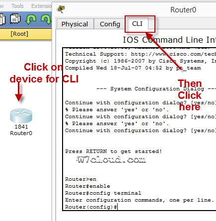
To configure any device in packet tracer you are required to open or access its CLI. You can do it by clicking any device and then navigating to CLI tab. Once you are at CLI you can perform all Cisco Commands here.

Cisco IOS supports numerous command modes which can be practice with packet tracer, followings are the main command modes of cisco CLI with specific commands to navigate from one mode to another. Also Check out some best cheap routers for real practice.
| Mode | Symbol | How to access this mode | Command for leaving this mode |
| User EXEC Mode | Router > | Default mode after booting. Press enter for accessing this. | Use exit command |
| Privileged EXEC mode | Router # | Use enable command from user exec mode for entering into this mode | exit |
| Global Configuration mode | Router(config)# | Use configure terminal command from privileged exec mode | Exit or Ctrl+Z for user EXEC mode |
| Interface Configuration | Router(config-if)# | Use interface <interface name+number> command from global configuration mode | Use exit command to return in global mode |
| ROMMON | ROMMON > | Enter reload command from privileged exec mode. Press CTRL + C key combination during the first 60 seconds of booting process. | Use exit command.
Watch a video of rommon mode |
IOS commands are not case sensitive it means that you can use them in uppercase, lowercase, or mixed case, but passwords are case sensitive. Therefore make sure you type it in correctly. In any mode, you can obtain a list of commands available on that mode by entering a question mark (?).
How to Change the Cisco Router name
You can change the cisco router name by using command hostname in global configuration mode.
![]()
How to set the Enable password:
You can set the password for protecting enable mode by following command: (Following command will set the password to cisco)
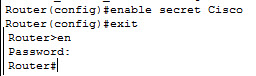
How to set the telnet password on Cisco:
You can access the cisco router remotely by VTY lines, these are the Virtual Terminal lines for access router, you can set password on these line by using the following commands:
Router(config)#line vty 0 4
Router(config-line)#password Cisco
Router(config-line)#no login
The above command will set the telnet password to “Cisco”.
How to set the IP address to Cisco interface:
You can set the IP address to any Cisco device interface by using the following commands:
Router(config)#interface <interface name&number>
Router(config-if)#ip address <IP address> <subnet mask>
How to enable a port or interface
Router(config-if)#no shut
Example:
![]()
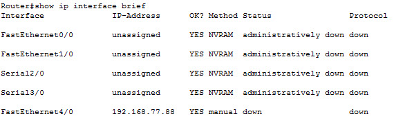
How to check the IP address of all interfaces:
You can use the “show ip interface brief” command in Privileged EXEC mode for checking the IP address of all interface of Cisco device.
How to save the configurations:
You can use the following command for router configuration to Nvram for use at next boot up
Router#copy running-config startup-config
How to configure the access-list on Cisco:
You can configure the access-list on cisco by using following commands:
Router(config)#Access-list <number> <permit|deny> <ip> <mask>
Router(config-if)#ip access-group <number> <in|out>
OR
Router(config)#Access-list <number> <permit|deny> <protocol> <from ip and mask> <to ip and mask> <port number>
Router(config-if)#
Command Example:
Router(config)#access-list 2 deny 192.168.0.33 0.0.0.255
Router(config)#interface fastEthernet 4/0
Router(config-if)#ip access-group 2 in
How to configure the default route on Cisco:
Following command will set the default route to 10.10.10.101.
Router(config)# ip route 0.0.0.0 0.0.0.0 10.10.10.101
How to create a static route on Cisco router
Router(config-router)#ip route [destination_network] [mask] [next-hop_address
you can set a static route by using above command example is also given below:
Router(config-router)#ip route 192.132.23.1 255.255.255.0 10.10.10.1
—————————
——————-
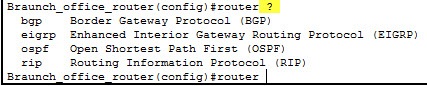
| RIP Configuration Commands | |
| Commands | Details |
| Router(config)#Router rip | Enable RIP routing on router. |
| Router(config-router)#Network <network ip address>
Why we use RIP? |
Define the network which you want to advertise in RIP. E.g. Network 192.168.88.0 |
|
OSPF Configuration Commands |
|
| Router(config)#Router ospf <process-id> | Enable OSPF routing on router. Process-id is any number & must be same for all networks in AS. |
| Router(config-router)#Network < ip address> <wild cardmask>
Why we use OSPF? |
IP address is the IP of network which will be advertise in OSPF and wild card mask will represent the network bits. E.g. network 192.168.1.0 0.0.255.255 is equilent to 192.168.0.0/16 |
| EIGRP configuration Commands | |
| Router(config)#Router eigrp <AS number> | AS number is a number must be same for networks which are desired to connect with each other. E.g. Router eigrp 1 |
| Router(config-router)#Network < ip address> | Advertise network in EIGRP |
| Router(config-router)#no auto-summary
Why we use EIGRP? |
Disable auto summay |
banner motd <banner start identification> banner message <banner end identification>
Command Example:
banner motd #Unauthorized access to this device is prohibited!#
Above command with set the banner to “Unauthorized access to this device is prohibited”
Famous Show Commands in Privileged EXEC Mode
You can run all these command for checking different setting of Cisco device in privileged EXEC mode:
Show Version
Show running-config
Show Vlan
Show mac-address-table
Show clock
Show privilege
Show interface <interface name>
show ip route
Show controllers
show cdp neighbors
Show memory
Show protocols
Show startup-config
Show Flash
Show spanning-tree
Verifying Commands for Network Connectivity
You can use these commands to verify network connectivity for your router
router# enable
router# ping [ip-address | hostname]
Command Example:
router# ping 192.168.3.1
(A reply response from host 192.168.3.1 will verify the connectivity)
How to telnet any host:
telnet {ip-address | hostname}
e.g. router# telnet 192.168.3.1
Related Article: NMAP Commands Linux

Me Waqas Azam and I am a professional blogger & freelance writer. I also working in the IT industry for over 7 years. I am graduated in Computer Science and information technology.
In order to help us complete the basic configuration of our Cisco routers, this lesson introduces the use of configuration modes, and how they interact to help us configure the router from the command-line interface (CLI). We will see configuration examples for basic interface components including IP addresses and then an overview of the show commands to verify proper configuration and operations.
Overview of Router Modes
The first step in configuring a router is to be located at privileged mode. Remember, exact modes have two sublevels: user and privileged. You go from user to privilege using the enable command and then from there you can only do monitoring and maintenance commands. If you want to configure, you have to go into global configuration mode at least, and you can accomplish that by typing configure terminal. That changes you to a different mode and the commands that you will have available are going to be different.
While in global configuration mode, anything you configure in that particular mode will affect the router as a whole typically, for example, the router’s host name and passwords and banners. If you want to configure specific components, then you would have to go into that components configuration mode from global configuration.
Router con0 is now available
Press RETURN to get started.
Router>enable
Router#configure terminal
Enter configuration commands, one per line. End with CNTL/Z.
Router(config)#
Router(config)#hostname Branch
Branch(config)#^Z
Branch#
*Feb 4 20:09:54.192: %SYS-5-CONFIG_I: Configured from console by console
Branch#
Interface configuration mode requires a command from global config and then the prompt changes to tell you that you are in a different configuration mode. This is similar for sub-interfaces, controllers, access lines and routing protocols. If you want to navigate back and forth between modes, exit takes you one mode back and Ctrl+Z takes you all the way back to privileged EXEC mode with no regards to your location. If you want to navigate between second level configuration modes, then you can do so without having to go back to global configuration mode.
Saving Configuration
The configuration process is typically ongoing and incremental. Administrators may even start the process by cutting text from configuration files and pasting it into the command-line interface. After that, they gradually configure different functions and different components of the router. During change management, new configurations and sections may appear. At all times, for every line that I type into or copy into the command-line interface and hit Enter, that configuration command is going to be active and available in the running configuration. If I boot up the router at that point, I will lose my configurations if I do not save them into the nonvolatile memory. This is again what is called the startup configuration. This command will help you save those configurations into NVRAM and it is recommended to use it frequently, especially during change management.
Branch#copy running-config startup-config
Destination filename [startup-config]?
Building configuration…
[OK]
Branch#
Or:
Branch#write memory
Building configuration…
[OK]
Configuring Router Identification
Accurate and effective documentation in sign posting is always a good practice. Router configuration is no exception and so here we see some commands that will allow you to document your settings and provide visual aids to identify certain components. For example, the host name of the router will be used as your router prompt.
At the command-line interface, the first word you see is the host name. For users connecting to the router, a good banner when they log in or when they access via any of the access lines will be an effective tool to convey the message of policies, access times, or support information. In configuring and changing the router configuration, it is probably important to provide descriptions to different components and so you will have a description command in interface configuration mode that allows you to then identify the interface when you use the show commands.
Console-Line Commands
Another important function in configuring the router is security and access control. The first command there could mitigate the exposure caused by lack of physical security. If someone accesses the console, and they suddenly leave, someone else could come in and use that session to their advantage: view the configurations, view the passwords, or even change them. The exec-timeout command allows you to set up a time out for command-line interface shells. In example, the console connection will time out and relogin the users after 20 minutes and 30 seconds.
Branch(config)#
Branch(config)#line vty 0 4
Branch(config-line)#exec-timeout ?
<0-35791> Timeout in minutesBranch(config-line)#exec-timeout 20 ?
<0-2147483> Timeout in seconds
<cr>Branch(config-line)#exec-timeout 20 30 ?
<cr>Branch(config-line)#exec-timeout 20 30
Some other times you may want to prevent a denial of service attack that we inflict on ourselves. For example, when you are troubleshooting a router, you may enable a good number of messages to be displayed on the console, so that you can see what is going on. Well, that may prevent you from typing commands to fix a problem and so logging synchronous is a command that allows us to redisplay the interrupted console input after a message has been displayed. In other words, I am typing, a message is displayed, well the command I was typing is redisplayed on the screen, so I can follow up and continue typing and fixing the problems.
Branch(config-line)#logging synchronous
Branch(config-line)#end
Branch#wr
Building configuration…
[OK]
Branch#
Configuring an Interface
Interfaces are the door to other networks and are one of the things that makes the router a router, the device capable of connecting multiple segments, so their configuration is going to be critical. You can configure interfaces by going into the interface configuration mode, and you do this by typing the command interface and then the interface identifier.
Typically, the interface identifier will depend on the type of router we have and so there are some fixed configuration routers that will simply have Ethernet 0 as an example or Serial 0 as another example. In modular routers, the interface identifier depends on the location of the interface in terms of the various slots and modules in the router chassis. At that point, you would identify the interface with a number and the number is going to be a slot followed by a / followed by a port, and so if the interface I want to accesses is on slot 1 and it is port number 3, then it would be 1/3.
Configuring an Interface Description
It is very important to be able to identify quickly the various components of our configuration. Interface names and numbers are sometimes not too pneumonic or suitable to remember what they are all about. It will be better to know an interface by calling it interface 2 branch 1 than by calling it as 00.
So good description will come handy; it will improve your documentation and will be very effective in troubleshooting. That is the command to assign an interface, a description, and as you can imagine, it is an interface configuration mode command.
Disabling or Enabling an Interface
Interfaces have multiple statuses, and they relate to layers 1 and 2 in the display of our commands. For example, if I do show IP interfaces brief, the output of that command will display the layer 1 status and layer 2 status. One possible status is down and this could happen due to lack of service or signal on a certain interface or due to misconfigurations.
At some point, during troubleshooting or during change management, administrators may want to bring the interface down administratively. These commands show how to do it. The shut down command in interface configuration mode disables the interface, while the no version of the same command will enable the interface. The no keyword is valid for several commands, not only this one, and allows you to negate or revert the action of a certain command.
Configuring IP Address
IP addresses are the building block to IP communications. In a router, any active IP interface will require an IP address. Setting the IP address includes setting of the address itself plus the mask. The mask tells the router how to read the IP address and understand in terms of networks and hosts. Following proper design guidelines you should reach a consensus in terms of how IP addresses are going to be allocated and assigned to different segments and hosts in the network.
In routers, again, all interfaces that transport IP will need one; this also helps the router in defining the topology of the directly connected networks and be able to advertise those networks to other devices via routing protocols. The router’s IP addresses will also sometimes serve as a default gateway to configure on other devices and hosts.
Branch#conf t
Enter configuration commands, one per line. End with CNTL/Z.
Branch(config)#interface fa0/0
Branch(config-if)#ip address 192.168.10.1 255.255.255.0
Branch(config-if)#description ### LAN ###
Branch(config-if)#no shutdown
Branch(config-if)#
*Feb 4 20:21:05.434: %LINK-3-UPDOWN: Interface FastEthernet0/0, changed state to up
*Feb 4 20:21:06.435: %LINEPROTO-5-UPDOWN: Line protocol on Interface FastEthernet0/0, changed state to up
Branch(config-if)#
Branch(config-if)#exi
Branch(config)#int fa0/1
Branch(config-if)#ip address 10.1.5.2 255.255.255.252
Branch(config-if)#description ### Internet ###
Branch(config-if)#no shu
*Feb 4 20:22:32.896: %LINK-3-UPDOWN: Interface FastEthernet0/1, changed state to up
*Feb 4 20:22:33.899: %LINEPROTO-5-UPDOWN: Line protocol on Interface FastEthernet0/1, changed state to up
Branch(config-if)#end
Branch#
Branch#wr
Building configuration…
[OK]
Branch#
Router show interface Command
Multiple commands are available to verify your configuration; show interfaces is perhaps one of the commands that displays the most information in its output. The basic version of the command will actually display the MAC addresses and IP addresses as well as valuable statistics in terms of number received and transmitted packets and put an output rates and layer 1 and layer 2 counters. Do yourself a favour and try to memorize the following two very useful and important commands!
Branch#show ip interface brief
Interface IP-Address OK? Method Status Protocol
FastEthernet0/0 192.168.10.1 YES manual up up
FastEthernet0/1 10.1.5.2 YES manual up up
Branch#show interfaces description
Interface Status Protocol Description
Fa0/0 up up ### LAN ###
Fa0/1 up up ### Internet ###
…
Branch#
Interpreting the Interface Status
The first line of our show interfaces command is the actual status of the interface, and again this is broken into two different statuses, one per layer. The first status is layer 1, the second status is layer 2, and so you can see here some of the combinations that will represent a different overall status of the interface.
Router#sh int fa 0
FastEthernet0 is up, line protocol is up
Hardware is PQ3_TSEC, address is 0021.a09d.1b6c (bia 0021.a09d.1b6c)
Description: ### PROVIDER ###
Internet address is 192.168.0.65/24
MTU 1500 bytes, BW 100000 Kbit/sec, DLY 100 usec,
reliability 255/255, txload 1/255, rxload 1/255
Encapsulation ARPA, loopback not set
Keepalive set (10 sec)
Full-duplex, 100Mb/s, 100BaseTX/FX
ARP type: ARPA, ARP Timeout 04:00:00
Last input 00:00:00, output 00:00:00, output hang never
Last clearing of “show interface” counters never
Input queue: 0/75/0/0 (size/max/drops/flushes); Total output drops: 39
Queueing strategy: fifo
Output queue: 0/40 (size/max)
5 minute input rate 2000 bits/sec, 1 packets/sec
5 minute output rate 1000 bits/sec, 1 packets/sec
491094 packets input, 487489009 bytes
Received 245 broadcasts, 0 runts, 0 giants, 0 throttles
0 input errors, 0 CRC, 0 frame, 0 overrun, 0 ignored
0 watchdog
0 input packets with dribble condition detected
386363 packets output, 74996232 bytes, 0 underruns
0 output errors, 0 collisions, 0 interface resets
0 unknown protocol drops
0 babbles, 0 late collision, 0 deferred
0 lost carrier, 0 no carrier
0 output buffer failures, 0 output buffers swapped out
If both components are up, then status is operational. If the physical layer is up, but the data link layer is down, then there may be a connection problem related to say Ethernet. In the case of serial interfaces, this may be an indication of lack of keepalives or mismatched encapsulation types. If both statuses are down, then that probably means that there is no cable attached to the port. Finally, when you shut down the interface, it will show as administratively down.
Navigating the CLI
Let’s review the navigation tools and some of the commands that may come handy. We know that here at privileged mode, we can go into global configuration by doing the config T, and then from there, to further other configuration modes like interface configuration mode, like that, for that particular interface. Now from here, we cannot do show commands initially because those belong to the EXEC mode and we are in interface configuration mode. So, if I do things like show ip int brief from here, it says no, you can’t because it is not available in this mode. Well, I can always use a do version of the command. Do will invoke commands that belong to EXEC mode. And so, if I do that, then it displays the output of the show IP interface brief while I am still at the interface configuration mode. Now, if I wanted to navigate and move back and forth, I can use the exit command to go back one level or one section. If I go back to interface configuration mode, though, and want to go all the way back into the EXEC mode, I can do Ctrl-Z, and then that is going to do it. Another command that may come handy is how to break, or abort, certain things. For example, the default behavior if I type an unknown command is to look up that word via DNS and try to resolve it to an IP address and Telnet to it. All that may take a little time. So, if I do that and start looking it up, I can use the keywords to abort, which are Ctrl-Shift-6, and that thing aborts certain commands like this translation, and also ping and trace for testing. And that is going to come handy if you do not want to waste your time here. Useful stuff. Let’s move on.
Router#
Router#
Router#conf t
Enter configuration commands, one per line. End with CNTL/Z.
Router(config)#int fa 0
Router(config-if)#
Router(config-if)#sh ip int brie
^
% Invalid input detected at ‘^’ marker.Router(config-if)#do sh ip int brie
Interface IP-Address OK? Method Status Protocol
BRI0 unassigned YES NVRAM administratively down down
BRI0:1 unassigned YES unset administratively down down
BRI0:2 unassigned YES unset administratively down down
FastEthernet0 192.168.0.65 YES NVRAM up up
FastEthernet1 unassigned YES NVRAM administratively down down
FastEthernet2 unassigned YES unset down down
FastEthernet3 unassigned YES unset down down
FastEthernet4 unassigned YES unset up down
FastEthernet5 unassigned YES unset up down
FastEthernet6 unassigned YES unset up up
FastEthernet7 unassigned YES unset up up
FastEthernet8 unassigned YES unset up up
FastEthernet9 unassigned YES unset down down
NVI0 192.168.0.65 YES unset up up
Tunnel1 10.10.1.65 YES NVRAM up up
Tunnel2 10.10.2.65 YES NVRAM up up
Vlan1 192.168.65.192 YES NVRAM up up
Router(config-if)#
Router(config-if)#exi
Router(config)#
Router(config)#
Router(config)#int fa 0
Router(config-if)#
Router(config-if)#^Z
Router#
Router#unknown
Translating “unknown”Translating “unknown”
% Bad IP address or host name
% Unknown command or computer name, or unable to find computer address
Router#