Table Of Contents
Basic Router Configuration
Interface Port Labels
Viewing the Default Configuration
Information Needed for Configuration
Configuring Basic Parameters
Configure Global Parameters
Configure Fast Ethernet LAN Interfaces
Configure WAN Interfaces
Configure the Fast Ethernet WAN Interface
Configure the ATM WAN Interface
Configure the Wireless Interface
Configuring a Loopback Interface
Configuration Example
Verifying Your Configuration
Configuring Command-Line Access to the Router
Configuration Example
Configuring Static Routes
Configuration Example
Verifying Your Configuration
Configuring Dynamic Routes
Configuring RIP
Configuration Example
Verifying Your Configuration
Configuring Enhanced IGRP
Configuration Example
Verifying Your Configuration
Basic Router Configuration
This chapter provides procedures for configuring the basic parameters of your Cisco router, including global parameter settings, routing protocols, interfaces, and command-line access. It also describes the default configuration on startup.

Note ![]() Individual router models may not support every feature described throughout this guide. Features not supported by a particular router are indicated whenever possible.
Individual router models may not support every feature described throughout this guide. Features not supported by a particular router are indicated whenever possible.
This chapter contains the following sections:
•![]() Interface Port Labels
Interface Port Labels
•![]() Viewing the Default Configuration
Viewing the Default Configuration
•![]() Information Needed for Configuration
Information Needed for Configuration
•![]() Configuring Basic Parameters
Configuring Basic Parameters
•![]() Configuring Static Routes
Configuring Static Routes
•![]() Configuring Dynamic Routes
Configuring Dynamic Routes
•![]() Configuring Enhanced IGRP
Configuring Enhanced IGRP
Each section includes a configuration example and verification steps, as available.
For complete information on how to access global configuration mode, see the «Entering Global Configuration Mode» section in Appendix A, «Cisco IOS Basic Skills.» For more information on the commands used in the following tables, see the Cisco IOS Release 12.3 documentation set.
Interface Port Labels
Table 1-1 lists the interfaces supported for each router and their associated port labels on the equipment.
|
Router |
Interface |
Port Label |
|---|---|---|
|
Cisco 851 |
Fast Ethernet LAN |
LAN (top), FE0-FE3 (bottom) |
|
Fast Ethernet WAN |
WAN (top), FE4 (bottom) |
|
|
Wireless LAN |
(no label) |
|
|
Cisco 871 |
Fast Ethernet LAN |
FE0-FE3 |
|
Fast Ethernet WAN |
FE4 |
|
|
Wireless LAN |
LEFT, RIGHT/PRIMARY |
|
|
USB |
1-0 |
|
|
Cisco 857 |
Fast Ethernet LAN |
LAN (top), FE0-FE3 (bottom) |
|
ATM WAN |
ADSLoPOTS |
|
|
Wireless LAN |
(no label) |
|
|
Cisco 876 |
Fast Ethernet LAN |
LAN (top), FE0-FE3 (bottom) |
|
ATM WAN |
ADSLoISDN |
|
|
Wireless LAN |
LEFT, RIGHT/PRIMARY |
|
|
BRI |
ISDN S/T |
|
|
Cisco 877 |
Fast Ethernet LAN |
LAN (top), FE0-FE3 (bottom) |
|
ATM WAN |
ADSLoPOTS |
|
|
Wireless LAN |
LEFT, RIGHT/PRIMARY |
|
|
Cisco 878 |
Fast Ethernet LAN |
FE0-FE3 |
|
ATM WAN |
G.SHDSL |
|
|
Wireless LAN |
LEFT, RIGHT/PRIMARY |
|
|
BRI |
ISDN S/T |
Viewing the Default Configuration
When you first boot up your Cisco router, some basic configuration has already been performed. All of the LAN and WAN interfaces have been created, console and VTY ports are configured, and the inside interface for Network Address Translation has been assigned. Use the show running-config command to view the initial configuration, as shown in Example 1-1.
Example 1-1 Cisco 851 Default Configuration on Startup
Router# show running-config
Building configuration...
Current configuration : 1090 bytes
service timestamps debug datetime msec
service timestamps log datetime msec
no service password-encryption
no ftp-server write-enable
speed basic-1.0 basic-2.0 basic-5.5 6.0 9.0 basic-11.0 12.0 18.0 24.0 36.0 48.0
Information Needed for Configuration
You need to gather some or all of the following information, depending on your planned network scenario, prior to configuring your network
•![]() If you are setting up an Internet connection, gather the following information:
If you are setting up an Internet connection, gather the following information:
–![]() Point-to-Point Protocol (PPP) client name that is assigned as your login name
Point-to-Point Protocol (PPP) client name that is assigned as your login name
–![]() PPP authentication type: Challenge Handshake Authentication Protocol (CHAP) or Password Authentication Protocol (PAP)
PPP authentication type: Challenge Handshake Authentication Protocol (CHAP) or Password Authentication Protocol (PAP)
–![]() PPP password to access your Internet service provider (ISP) account
PPP password to access your Internet service provider (ISP) account
–![]() DNS server IP address and default gateways
DNS server IP address and default gateways
•![]() If you are setting up a connection to a corporate network, you and the network administrator must generate and share the following information for the WAN interfaces of the routers:
If you are setting up a connection to a corporate network, you and the network administrator must generate and share the following information for the WAN interfaces of the routers:
–![]() PPP authentication type: CHAP or PAP
PPP authentication type: CHAP or PAP
–![]() PPP client name to access the router
PPP client name to access the router
–![]() PPP password to access the router
PPP password to access the router
•![]() If you are setting up IP routing:
If you are setting up IP routing:
–![]() Generate the addressing scheme for your IP network.
Generate the addressing scheme for your IP network.
–![]() Determine the IP routing parameter information, including IP address, and ATM permanent virtual circuits (PVCs). These PVC parameters are typically virtual path identifier (VPI), virtual circuit identifier (VCI), and traffic shaping parameters.
Determine the IP routing parameter information, including IP address, and ATM permanent virtual circuits (PVCs). These PVC parameters are typically virtual path identifier (VPI), virtual circuit identifier (VCI), and traffic shaping parameters.
–![]() Determine the number of PVCs that your service provider has given you, along with their VPIs and VCIs.
Determine the number of PVCs that your service provider has given you, along with their VPIs and VCIs.
–![]() For each PVC determine the type of AAL5 encapsulation supported. It can be one of the following:
For each PVC determine the type of AAL5 encapsulation supported. It can be one of the following:
AAL5SNAP—This can be either routed RFC 1483 or bridged RFC 1483. For routed RFC 1483, the service provider must provide you with a static IP address. For bridged RFC 1483, you may use DHCP to obtain your IP address, or you may obtain a static IP address from your service provider.
AAL5MUX PPP—With this type of encapsulation, you need to determine the PPP-related configuration items.
•![]() If you plan to connect over an ADSL or G.SHDSL line:
If you plan to connect over an ADSL or G.SHDSL line:
–![]() Order the appropriate line from your public telephone service provider.
Order the appropriate line from your public telephone service provider.
For ADSL lines—Ensure that the ADSL signaling type is DMT (also called ANSI T1.413) or DMT Issue 2.
For G.SHDSL lines—Verify that the G.SHDSL line conforms to the ITU G.991.2 standard and supports Annex A (North America) or Annex B (Europe).
Once you have collected the appropriate information, you can perform a full configuration on your router, beginning with the tasks in the «Configuring Basic Parameters» section.
Configuring Basic Parameters
To configure the router, perform one or more of these tasks:
•![]() Configure Global Parameters
Configure Global Parameters
•![]() Configure Fast Ethernet LAN Interfaces
Configure Fast Ethernet LAN Interfaces
•![]() Configure WAN Interfaces
Configure WAN Interfaces
•![]() Configuring a Loopback Interface
Configuring a Loopback Interface
•![]() Configuring Command-Line Access to the Router
Configuring Command-Line Access to the Router
A configuration example is presented with each task to show the network configuration following completion of that task.
Configure Global Parameters
Perform these steps to configure selected global parameters for your router:
|
Command |
Purpose |
|
|---|---|---|
|
Step 1 |
configure terminal Example: Router> enable Router# configure terminal Router(config)# |
Enters global configuration mode, when using the console port. If you are connecting to the router using a remote terminal, use the following: telnet router name or address Login: login id Password: ********* Router> enable |
|
Step 2 |
hostname name Example: Router(config)# hostname Router Router(config)# |
Specifies the name for the router. |
|
Step 3 |
enable secret password Example: Router(config)# enable secret cr1ny5ho Router(config)# |
Specifies an encrypted password to prevent unauthorized access to the router. |
|
Step 4 |
no ip domain-lookup Example: Router(config)# no ip domain-lookup |
Disables the router from translating unfamiliar words (typos) into IP addresses. |
For complete information on the global parameter commands, see the Cisco IOS Release 12.3 documentation set.
Configure Fast Ethernet LAN Interfaces
The Fast Ethernet LAN interfaces on your router are automatically configured as part of the default VLAN and as such, they are not configured with individual addresses. Access is afforded through the VLAN. You may assign the interfaces to other VLANs if desired. For more information about creating VLANs, see Chapter 5 «Configuring a LAN with DHCP and VLANs.»
Configure WAN Interfaces
The Cisco 851 and Cisco 871 routers each have one Fast Ethernet interface for WAN connection. The Cisco 857, Cisco 877, and Cisco 878 routers each have one ATM interface for WAN connection.
Based on the router model you have, configure the WAN interface(s) using one of the following procedures:
•![]() Configure the Fast Ethernet WAN Interface
Configure the Fast Ethernet WAN Interface
•![]() Configure the ATM WAN Interface
Configure the ATM WAN Interface
Configure the Fast Ethernet WAN Interface
This procedure applies only to the Cisco 851 and Cisco 871 router models. Perform these steps to configure the Fast Ethernet interface, beginning in global configuration mode:
|
Command |
Purpose |
|
|---|---|---|
|
Step 1 |
interface type number Example: Router(config)# interface fastethernet 4
Router(config-int)# |
Enters the configuration mode for a Fast Ethernet WAN interface on the router. |
|
Step 2 |
ip address ip-address mask Example: Router(config-int)# ip address 192.168.12.2
255.255.255.0
Router(config-int)# |
Sets the IP address and subnet mask for the specified Fast Ethernet interface. |
|
Step 3 |
no shutdown Example: Router(config-int)# no shutdown
Router(config-int)# |
Enables the Ethernet interface, changing its state from administratively down to administratively up. |
|
Step 4 |
exit Example: Router(config-int)# exit
Router(config)# |
Exits configuration mode for the Fast Ethernet interface and returns to global configuration mode. |
Configure the ATM WAN Interface
This procedure applies only to the Cisco 857, Cisco 876, Cisco 877 and Cisco 878 models.
Perform these steps to configure the ATM interface, beginning in global configuration mode:
|
Command |
Purpose |
|
|---|---|---|
|
Step 1 |
For the Cisco 878 model only:
controller dsl 0 Example: Router(config)# controller dsl 0
Router(config-controller)# mode atm
Router(config-controller)# exit Router(config)# |
For routers using the G.SHDSL signaling, perform these commands. Ignore this step for routers using ADSL signaling. |
|
Step 2 |
interface type number Example: Router(config)# interface atm0
Router(config-int)# |
Identifies and enters the configuration mode for an ATM interface. |
|
Step 3 |
ip address ip-address mask Example: Router(config-int)# ip address 10.10.10.100
255.255.255.0
Router(config-int)# |
Sets the IP address and subnet mask for the ATM interface. |
|
Step 4 |
no shutdown Example: Router(config-int)# no shutdown
Router(config-int)# |
Enables the ATM 0 interface. |
|
Step 5 |
exit Example: Router(config-int)# exit
Router(config)# |
Exits configuration mode for the ATM interface and returns to global configuration mode. |
Configure the Wireless Interface
The wireless interface enables connection to the router through a wireless LAN connection. For more information about configuring a wireless connection, see Chapter 9 «Configuring a Wireless LAN Connection,» and the Cisco Access Router Wireless Configuration Guide.
Configuring a Loopback Interface
The loopback interface acts as a placeholder for the static IP address and provides default routing information.
For complete information on the loopback commands, see the Cisco IOS Release 12.3 documentation set.
Perform these steps to configure a loopback interface:
|
Command |
Purpose |
|
|---|---|---|
|
Step 1 |
interface type number Example: Router(config)# interface Loopback 0
Router(config-int)# |
Enters configuration mode for the loopback interface. |
|
Step 2 |
ip address ip-address mask Example: Router(config-int)# ip address 10.108.1.1
255.255.255.0
Router(config-int)# |
Sets the IP address and subnet mask for the loopback interface. |
|
Step 3 |
exit Example: Router(config-int)# exit
Router(config)# |
Exits configuration mode for the loopback interface and returns to global configuration mode. |
Configuration Example
The loopback interface in this sample configuration is used to support Network Address Translation (NAT) on the virtual-template interface. This configuration example shows the loopback interface configured on the Fast Ethernet interface with an IP address of 10.10.10.100/24, which acts as a static IP address. The loopback interface points back to virtual-template1, which has a negotiated IP address.
ip address 10.10.10.100 255.255.255.0 (static IP address)
interface Virtual-Template1
Verifying Your Configuration
To verify that you have properly configured the loopback interface, enter the show interface loopback command. You should see verification output similar to the following example.
Router# show interface loopback 0
Loopback0 is up, line protocol is up
Internet address is 10.10.10.100/24
MTU 1514 bytes, BW 8000000 Kbit, DLY 5000 usec,
reliability 255/255, txload 1/255, rxload 1/255
Encapsulation LOOPBACK, loopback not set
Last input never, output never, output hang never
Last clearing of "show interface" counters never
Output queue 0/0, 0 drops; input queue 0/75, 0 drops
5 minute input rate 0 bits/sec, 0 packets/sec
5 minute output rate 0 bits/sec, 0 packets/sec
0 packets input, 0 bytes, 0 no buffer
Received 0 broadcasts, 0 runts, 0 giants, 0 throttles
0 input errors, 0 CRC, 0 frame, 0 overrun, 0 ignored, 0 abort
0 packets output, 0 bytes, 0 underruns
0 output errors, 0 collisions, 0 interface resets
0 output buffer failures, 0 output buffers swapped out
Another way to verify the loopback interface is to ping it:
Router# ping 10.10.10.100
Type escape sequence to abort.
Sending 5, 100-byte ICMP Echos to 10.10.10.100, timeout is 2 seconds:
Success rate is 100 percent (5/5), round-trip min/avg/max = 1/2/4 ms
Configuring Command-Line Access to the Router
Perform these steps to configure parameters to control access to the router, beginning in global configuration mode.
|
Command |
Purpose |
|
|---|---|---|
|
Step 1 |
line [aux | console | tty | vty] line-number Example: Router(config)# line console 0
Router(config)# |
Enters line configuration mode, and specifies the type of line. This example specifies a console terminal for access. |
|
Step 2 |
password password Example: Router(config)# password 5dr4Hepw3
Router(config)# |
Specifies a unique password for the console terminal line. |
|
Step 3 |
login Example: Router(config)# login
Router(config)# |
Enables password checking at terminal session login. |
|
Step 4 |
exec-timeout minutes [seconds] Example: Router(config)# exec-timeout 5 30
Router(config)# |
Sets the interval that the EXEC command interpreter waits until user input is detected. The default is 10 minutes. Optionally, add seconds to the interval value. This example shows a timeout of 5 minutes and 30 seconds. Entering a timeout of 0 0 specifies never to time out. |
|
Step 5 |
line [aux | console | tty | vty] line-number Example: Router(config)# line vty 0 4
Router(config)# |
Specifies a virtual terminal for remote console access. |
|
Step 6 |
password password Example: Router(config)# password aldf2ad1
Router(config)# |
Specifies a unique password for the virtual terminal line. |
|
Step 7 |
login Example: Router(config)# login
Router(config)# |
Enables password checking at the virtual terminal session login. |
|
Step 8 |
end Example: Router(config)# end
Router# |
Exits line configuration mode, and returns to privileged EXEC mode. |
For complete information about the command line commands, see the Cisco IOS Release 12.3 documentation set.
Configuration Example
The following configuration shows the command-line access commands.
You do not need to input the commands marked «default.» These commands appear automatically in the configuration file generated when you use the show running-config command.
transport input none (default)
Configuring Static Routes
Static routes provide fixed routing paths through the network. They are manually configured on the router. If the network topology changes, the static route must be updated with a new route. Static routes are private routes unless they are redistributed by a routing protocol. Configuring static routes on the Cisco 850 and Cisco 870 series routers is optional.
Perform these steps to configure static routes, beginning in global configuration mode:
|
Command |
Purpose |
|
|---|---|---|
|
Step 1 |
ip route prefix mask {ip-address | interface-type interface-number [ip-address]} Example: Router(config)# ip route 192.168.1.0
255.255.0.0 10.10.10.2
Router(config)# |
Specifies the static route for the IP packets. For details about this command and additional parameters that can be set, see the Cisco IOS IP Command Reference, Volume 2 of 4: Routing Protocols. |
|
Step 2 |
end Example: Router(config)# end
Router# |
Exits router configuration mode, and enters privileged EXEC mode. |
For complete information on the static routing commands, see the Cisco IOS Release 12.3 documentation set. For more general information on static routing, see «Concepts.»
Configuration Example
In the following configuration example, the static route sends out all IP packets with a destination IP address of 192.168.1.0 and a subnet mask of 255.255.255.0 on the Fast Ethernet interface to another device with an IP address of 10.10.10.2. Specifically, the packets are sent to the configured PVC.
You do not need to enter the commands marked «(default).» These commands appear automatically in the configuration file generated when you use the show running-config command.
ip route 192.168.1.0 255.255.255.0 10.10.10.2!
Verifying Your Configuration
To verify that you have properly configured static routing, enter the show ip route command and look for static routes signified by the «S.»
You should see verification output similar to the following example.
Codes: C - connected, S - static, R - RIP, M - mobile, B - BGP
D - EIGRP, EX - EIGRP external, O - OSPF, IA - OSPF inter area
N1 - OSPF NSSA external type 1, N2 - OSPF NSSA external type 2
E1 - OSPF external type 1, E2 - OSPF external type 2
i - IS-IS, su - IS-IS summary, L1 - IS-IS level-1, L2 - IS-IS level-2
ia - IS-IS inter area, * - candidate default, U - per-user static route
o - ODR, P - periodic downloaded static route
Gateway of last resort is not set
10.0.0.0/24 is subnetted, 1 subnets
C 10.108.1.0 is directly connected, Loopback0
S* 0.0.0.0/0 is directly connected, FastEthernet0
Configuring Dynamic Routes
In dynamic routing, the network protocol adjusts the path automatically, based on network traffic or topology. Changes in dynamic routes are shared with other routers in the network.
The Cisco routers can use IP routing protocols, such as Routing Information Protocol (RIP) or Enhanced Interior Gateway Routing Protocol (EIGRP), to learn routes dynamically. You can configure either of these routing protocols on your router.
Configuring RIP
Perform these steps to configure the RIP routing protocol on the router, beginning in global configuration mode:
|
Command |
Task |
|
|---|---|---|
|
Step 1 |
router rip Example: Router> configure terminal
Router(config)# router rip
Router(config-router)# |
Enters router configuration mode, and enables RIP on the router. |
|
Step 2 |
version {1 | 2} Example: Router(config-router)# version 2
Router(config-router)# |
Specifies use of RIP version 1 or 2. |
|
Step 3 |
network ip-address Example: Router(config-router)# network 192.168.1.1
Router(config-router)# network 10.10.7.1
Router(config-router)# |
Specifies a list of networks on which RIP is to be applied, using the address of the network of directly connected networks. |
|
Step 4 |
no auto-summary Example: Router(config-router)# no auto-summary
Router(config-router)# |
Disables automatic summarization of subnet routes into network-level routes. This allows subprefix routing information to pass across classful network boundaries. |
|
Step 5 |
end Example: Router(config-router)# end
Router# |
Exits router configuration mode, and enters privileged EXEC mode. |
For complete information on the dynamic routing commands, see the Cisco IOS Release 12.3 documentation set. For more general information on RIP, see «Concepts.»
Configuration Example
The following configuration example shows RIP version 2 enabled in IP network 10.0.0.0 and 192.168.1.0.
Execute the show running-config command from privileged EXEC mode to see this configuration.
Verifying Your Configuration
To verify that you have properly configured RIP, enter the show ip route command and look for RIP routes signified by «R.» You should see a verification output like the example shown below.
Codes: C - connected, S - static, R - RIP, M - mobile, B - BGP
D - EIGRP, EX - EIGRP external, O - OSPF, IA - OSPF inter area
N1 - OSPF NSSA external type 1, N2 - OSPF NSSA external type 2
E1 - OSPF external type 1, E2 - OSPF external type 2
i - IS-IS, su - IS-IS summary, L1 - IS-IS level-1, L2 - IS-IS level-2
ia - IS-IS inter area, * - candidate default, U - per-user static route
o - ODR, P - periodic downloaded static route
Gateway of last resort is not set
10.0.0.0/24 is subnetted, 1 subnets
C 10.108.1.0 is directly connected, Loopback0
R 3.0.0.0/8 [120/1] via 2.2.2.1, 00:00:02, Ethernet0/0
Configuring Enhanced IGRP
Perform these steps to configure Enhanced IGRP (EIGRP), beginning in global configuration mode:
|
Command |
Purpose |
|
|---|---|---|
|
Step 1 |
router eigrp as-number Example: Router(config)# router eigrp 109
Router(config)# |
Enters router configuration mode, and enables EIGRP on the router. The autonomous-system number identifies the route to other EIGRP routers and is used to tag the EIGRP information. |
|
Step 2 |
network ip-address Example: Router(config)# network 192.145.1.0
Router(config)# network 10.10.12.115
Router(config)# |
Specifies a list of networks on which EIGRP is to be applied, using the IP address of the network of directly connected networks. |
|
Step 3 |
end Example: Router(config-router)# end
Router# |
Exits router configuration mode, and enters privileged EXEC mode. |
For complete information on the IP EIGRP commands, see the Cisco IOS Release 12.3 documentation set. For more general information on EIGRP concepts, see «Concepts.»
Configuration Example
The following configuration example shows the EIGRP routing protocol enabled in IP networks 192.145.1.0 and 10.10.12.115. The EIGRP autonomous system number is 109.
Execute the show running-config command from privileged EXEC mode to see this configuration.
Verifying Your Configuration
To verify that you have properly configured IP EIGRP, enter the show ip route command, and look for EIGRP routes indicated by «D.» You should see verification output similar to the following example.
Codes: C - connected, S - static, R - RIP, M - mobile, B - BGP
D - EIGRP, EX - EIGRP external, O - OSPF, IA - OSPF inter area
N1 - OSPF NSSA external type 1, N2 - OSPF NSSA external type 2
E1 - OSPF external type 1, E2 - OSPF external type 2
i - IS-IS, su - IS-IS summary, L1 - IS-IS level-1, L2 - IS-IS level-2
ia - IS-IS inter area, * - candidate default, U - per-user static route
o - ODR, P - periodic downloaded static route
Gateway of last resort is not set
10.0.0.0/24 is subnetted, 1 subnets
C 10.108.1.0 is directly connected, Loopback0
D 3.0.0.0/8 [90/409600] via 2.2.2.1, 00:00:02, Ethernet0/0
В данной статье мы рассмотрим процесс подключения и настройки роутера в сети Cisco. Узнаем, как включить и выключить роутер, а также как получить доступ к его настройкам.
- Подключение роутера
- Включение роутера в Cisco Packet Tracer
- Настройка роутера
- Вход в настройки роутера Cisco
- Полезные советы и выводы
Подключение роутера
Для начала работы с роутером, необходимо правильно подключить его к электросети и компьютеру. Для этого выполним следующие шаги:
- Подключите роутер к электросети с помощью кабеля питания.
- На задней панели роутера найдите кнопку Power и нажмите ее, чтобы включить роутер.
- Соедините компьютер с роутером при помощи кабеля, который поставляется в комплекте с роутером (патч-кордом).
Теперь роутер готов к настройке и использованию.
Включение роутера в Cisco Packet Tracer
Для того чтобы включить роутер в программе Cisco Packet Tracer, необходимо выполнить следующие действия:
- Зайдите в режим конфигурации роутера.
- Выполните команду `shutdown` для отключения нужного VLAN.
После выполнения этих действий выбранный VLAN будет выключен.
Настройка роутера
Для доступа к настройкам роутера, необходимо выполнить следующие шаги:
- В адресной строке браузера введите IP-адрес роутера. Обычно это 192.168.1.1 или 192.168.0.1.
- Нажмите клавишу Enter.
- В появившемся окне введите имя пользователя и пароль. По умолчанию, как правило, используется admin и admin.
Теперь у вас открылся доступ к настройкам роутера. Вы можете изменять различные параметры и выполнять необходимые конфигурации.
Вход в настройки роутера Cisco
Для доступа к настройкам роутера Cisco, выполните следующие действия:
- Запустите браузер.
- В адресной строке введите IP-адрес роутера. Обычно это 192.168.1.1 или 192.168.0.1.
- Введите стандартное имя пользователя — admin, и пароль — admin.
Теперь вы получили доступ к веб-интерфейсу роутера и можете вносить необходимые изменения в его настройки.
Полезные советы и выводы
- Перед подключением роутера проверьте, что кабели правильно подключены и роутер подключен к электросети.
- Запомните или запишите в безопасном месте IP-адрес, имя пользователя и пароль роутера для последующего доступа к его настройкам.
- При настройке роутера, будьте внимательны и осторожны, чтобы не повредить его или сеть.
В данной статье мы рассмотрели основные шаги по подключению и настройке роутера в сети Cisco. Используя представленную информацию, вы сможете успешно включить и настроить роутер, а также получить доступ к его настройкам.
Как зайти в настройки роутера в режиме повторителя
Как зайти в настройки роутера в режиме повторителя? Для начала, нужно проверить подключение к репитеру, даже если оно не имеет доступа к интернету — это не проблема. Затем необходимо открыть браузер и в адресную строку ввести следующий адрес: 192.168.10.1. Далее, вводим имя пользователя и пароль, которые могут быть установлены по умолчанию. Предлагается использовать admin в качестве имени пользователя и пароль. Если это не работает, лучше обратиться к инструкции роутера, чтобы узнать правильные данные для входа. После ввода имени пользователя и пароля мы попадаем в интерфейс настроек роутера, где можно изменить необходимые параметры в режиме повторителя.
Как подключить телевизор к интернету через Wi-Fi роутер
Подключение телевизора к интернету через Wi-Fi роутер возможно с помощью ручной настройки устройства. Для этого необходимо открыть настройки телевизора, используя пульт или кнопки, расположенные на самом телевизоре. Затем нужно перейти в раздел «Беспроводной тип сети» или аналогичный блок. Далее необходимо найти имя своей сети Wi-Fi в списке доступных и выбрать ее. После этого следует ввести пароль от своей беспроводной сети и нажать на соответствующую кнопку. Оставляйте все поля по умолчанию, если не уверены в их назначении. После выполнения всех этих шагов нужно дождаться успешного соединения. Теперь телевизор будет подключен к интернету через Wi-Fi роутер, и вы сможете использовать различные онлайн-сервисы и просматривать контент из интернета на большом экране.
Как посмотреть настройки роутера Ростелеком
Чтобы открыть настройки роутера, нужно ввести одну из этих адресов в адресную строку браузера. После этого откроется страница авторизации, где нужно ввести логин и пароль администратора роутера. Обычно эти данные указаны на самом устройстве или в договоре на его подключение. Если данные неизвестны или были изменены, их можно восстановить, сбросив настройки роутера до заводских. После успешного входа в настройки откроется страница с различными параметрами и функциями роутера. Тут можно изменить имя и пароль Wi-Fi сети, настроить порты и протоколы для подключенных устройств, настроить фильтры доступа и прочее. Внимательно проводить изменения нужно, чтобы не нарушить работу сети и подключенных устройств.
Как настроить вай фай на роутере TP-Link
Для начала настройки вай-фай на роутере TP-Link, необходимо зайти в раздел «Мои устройства» на компьютере или смартфоне. Затем выбрать из списка маршрутизатор и нажать на него. После этого следует нажать кнопку «Далее».
Далее, подключите роутер к электрической розетке и подключитесь к появившейся сети Wi-Fi на вашем смартфоне. Вам нужно будет ввести логин и пароль от сети.
Далее, войдите в настройки маршрутизатора. Для этого откройте браузер и в адресной строке введите IP-адрес вашего роутера. Вам будет предложено ввести логин и пароль от настроек роутера. После успешной авторизации, вы попадете в настройки маршрутизатора.
В разделе «Настройки безопасности» выберите вкладку «Wireless» и настройте параметры беспроводной сети. Установите имя сети (SSID) и пароль для доступа к вашей Wi-Fi-сети. После настройки, не забудьте сохранить изменения.
Начинаем курс статей под кодовым названием Cisco для новичков
Собственно сабжект говорит о том что я постараюсь описать в данной статье…
Имеем Cisco 2911… поехали
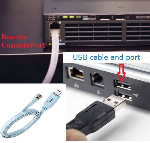
начну с того, что на 18XX 28XX и почих маршрутизаторах 8 серии подключение и первоначальная настройка оборудования осуществляется через консольный порт с разъемом RJ-45, обычно, кабель для настройки идет в комплекте, представляет из себя RJ-45 на RS-232 голубого цвета. Оборудование 19XX 29XX серий помимо консольного порта RJ 45 имеет консольный порт MiniUSB (Что значительно удобнее при настройке оборудования имея под рукой ноутбук с отсутствующим COM портом). Для настройки оборудования через MiniUSB нам понадобится драйвер эмуляции
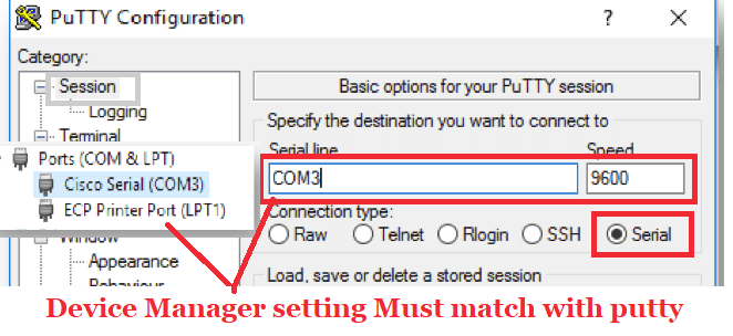
Далее в Device Manager появится Cisco Serial где можно настроить номер порта.
Установка соединения осуществляется со стандартными значениями – 9600 бод/8 бит данных/1 стоп бит/без проверки четности и контроля прохождения. В Windows – системах вы можете использовать putty, в Linux cu или minicom. В дальнейшем, когда маршрутизатору будет присвоен IP-адрес для настроек будем использовать ssh, но первый раз без консольного подключения не обойтись.
Открываем Putty, выбираем тип подключения Serial порт COM7 ( У меня он COM7) нажимаем 2 раза [Enter] и видим меред собой командную строку с приглашением роутера
Router>
Переходим в превелегированный режим командой enable
Router>enable
Router#
удаляем имеющуюся конфигурацию, находящуюся во флэш-памяти, и перезагружаем маршрутизатор:
Router#erase startup-config
Router#reload
Ждем пока роутер перезагрузится, наблюдая за процессом загрузки в окне консоли, после чего снова переходим в превилигированный режим
Router>enable
Переходим в конфигурационный режим и даем команду hostname:
Router#configure terminal
Enter configuration commands, one per line. End with CNTL/Z.
Router(config)#hostname Gw0
Gw0(config)#
Включим режим хранения паролей в файле конфигурации устройства в зашифрованном виде:
Gw0(config)#service password-encryption
Отключим управление маршрутизатором через http и https и CDP
Gw0(config)#no ip http server
Gw0(config)#no ip http secure-server
Gw0(config)#no cdp run
Зададим пароли на подключения через консольный порт
Gw0(config)#line con 0
Gw0(config-line)#password пароль
Gw0(config-line)#login
Gw0(config-line)#exit
И Telnet
Gw0(config)#line vty ? О, сколько он там сказал доступно? 0-1441 значит line vty 0 1441 ))
Gw0(config-line)#password пароль
Gw0(config-line)#login
Gw0(config-line)#exit
Зададим пароль на Enable режим
Gw0(config) enable secret пароль_enable_режима
Перейдем к настройке интерфейса внутренней сети. Если маршрутизатор имеет гигабитные порты то названия портов можно сократить как Gi 0/0 (Gigabit ethernet) , если 100 Мбитные то скорее всего это будут Fa (fast ethernet)
В принципе, если вы сомневаетесь в команде, нажмите TAB — в командной строке команда дописалась? значит норма, не помните что вводить? введите знак вопроса… IOS выдаст вам все доступные команды в данном контексте.
Gw0(config) #interface Gi 0/0
Gw0(config-if)#ip address 192.168.0.1 255.255.255.0
Gw0(config-if)#description LAN
Gw0(config-if)#no shutdown
Gw0(config-if)#exit
Задаем dns-сервера
Gw0(config)# ip name-server 192.168.0.2
Все, маршрутизатор доступен телнетом по 192.168.0.1
Записываем конфигурацию в память командой
Gw0# copy running-config startup config или командой wr
В следующей статье,собственно, мы отключим доступ на маршрутизатор через telnet (Ибо не секюрно ) и настроим доступ к нему используя SSH.
To be contined
This article is a complete Guide on Cisco Router Configuration with Details. I have divided this article into three parts i.e.
- Basic cisco router configuration step by step
- Advanced cisco router configuration
- Cisco GUI Configurations
Cisco Router Configuration For Beginners
I want to make it clear that this cisco configuration tutorial is for cisco learners. Although I have tried to cover the most topics, but visit Cisco’s website for more details and advanced configuration.
In basic Cisco router configurations, we will review all basic steps for configuration of a router and then see all basic Cisco CLI commands.
Basic Cisco router Configuration step by step
In Order to configure a cisco router you need to access the router CLI interface. You can do this in numerous ways. Here I am show you the most basic way to access a cisco router that is access Cisco router through console cable. Most for configuring a brand new router you need to adopt this method.
Access Cisco router with USB Console cable
Old console connection came with the DB-9 to console connection. But now a USB console connections are being used in market. You see this connection in following figure and you can connect it according to this.
Once your connection setting is complete, you are required a software for access the router CLI. Putty is the most famous and easy to use software. You can download it free from internet. For making the connection to your router you need to confirm the com-port number, open device manage and find the com port number under the “Ports (COM & LPT)”. Open the putty and give the same serial line as you find in device manage and click connect.
You can use any other software for creating a connection to router.
What are Three Modes in Cisco Router configuration?
Once you have a physical connection with your Cisco Router, you can configure it. Before Going into configurations of Cisco Router, let introduce you the basic configuration modes of Cisco. There are 3 modes or command-levels in Cisco router. In each command mode you have specific privileges and control.
- User Mode
- Privileged EXEC Mode
- Global_Configuration Mode
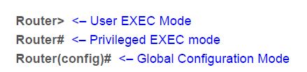
Cisco User Mode Cisco:
In first command mode of cisco you can run limited type of show commands, basic reachability tests. This command mode is represented by symbol “>”.
Cisco Privileged Mode
Privileged EXEC is second command level mode with the symbol “#”. Use “enable” command in user mode for accessing the privileged mode. In this mode you can have access to all monitoring commands of router.
What is global configuration mode of cisco router?
The Global configuration mode is for administrator where you can configure your Cisco router and the running configuration. You can access global configuration mode from Privileged EXEC mode using a command “configure terminal”. For more Cisco Global configuration mode Commands you can visit here.
How to Check Current Configurations on Cisco Router?
Once your cisco router is boot up you can check already performed configuration or default configuration Using command show running-config. If you are new to cisco just run this command in privileged mode this will give you a brief of all physical interfaces of cisco routers as well as all the protocols configuration.
What are Different types of passwords you can set on CISCO Router?
You can set different types of password on each command level mode, which will make your router secure.
How to configure console Password on Cisco Router?
The most basic password that you can configure on cisco router is to set the console password. This password blocks the unauthorized access through console cable on Cisco router. You can set the console password by using the following commands.
Router2>enable
Router2# configure terminal
Router2(config)#line console 0
Router2(config-line)#password cisco
Router2(config-line)#login
Above command will set the console password of router to “cisco”.
How to set enable password?
With the enable password you can secure privilege exec mode. You can set enable password in two ways. Both commands will set the enable password but the difference is first command will save the password in clear text which will be visible in show running-config, whereas the enable secret will save the password in encrypted form.
router(config)# enable password cisco
or
router(config)# enable secret cisco
How to set the Telnet password on Cisco Router?
Telnet password is used to secure your remote access to cisco router. By default there are five VTY line ot connections available but it may vary depending upon the version of Cisco router. You can set the telnet password by using these commands:
Router(config)#line vty 0 (This command will Set password to cisco on five vty lines)
Router(config-line)#password cisco
Router(config-line)#login
How to configure Cisco Router Host name?
After securing your router with different password, the most basic setting is to change the router name or host name of your cisco router. You can accomplish this by executing a cisco command “Hostname <router_new_name>” in global configuration mode.
Router(config)# hostname home_router

home_router(config)#
Above command will set the hostname to “home_router”
Disable automatic domain lookup
If you are beginner then it is better to turn off automatic domain lookup. It will save your time because if domain lookup is not disabled then router tries to resolve every word that is not a command. And every incorrectly typed command will result a wait of one or two minute. To understand the concept of automatic domain lookup any random word on cisco router and press enter and see the results. You can disable it with the help of command:
Router(config)# no ip domain-lookup
Configure IP address of Cisco Router
Configuring an IP address of a Cisco router is a most common and easy task. You can setting the IP address to any router interface with the following details
- Choose the interface by number.
- Specify the interface number.
- Specify the IP address and Subnet mask
You can check all the interfaces of a router by using the command “show ip interface brief” this will display all the interfaces of your Cisco router. Now select interface you want to configure. There are different type of interfaces available in Cisco router e.g. Ethernet, fastethernet, serial interfaces etc
You can configure all type of interface in a same way. Following commands can be used for configuring the Cisco router interfaces
Router(config)# Interface <interface_type & number>

Router(config-if)#ip address <IP_Address of interface> <Subnet Mask>

Router(config-if)#no shutdown
Following are the examples of different interfaces configurations on Cisco router:
| Sr | FastEthernet Interface | Serial Interface |
Router(config)#interface fastethernet 0/0 |
Router(config)#interface serial 0/0/0DCE side only command. Assigns a clock rate for the interfaceRouter(config-if)#bandwidth 64n |
What is a loopback interface used for & how to Configure it?
The Loopback interfaces are not physical interface but these are the logical interfaces used for different purpose. Loopback interface remain always up and most network professional use these interfaces for testing to test IP software without worrying about broken or corrupted drivers or hardware. A different IP scheme is designated for loopback IP address with start number 127.0.0.1. You can configure the loopback interface on Cisco Router with commands as under:
Router1(config)#interface loopback 1

Router1(config-if)#ip address 127.2.0.1 255.0.0.0

Router1(config-if)#no shutdown
Router1(config)#interface loopback 2

Router1(config-if)#ip address 127.3.0.2 255.0.0.0

Router1(config-if)#no shutdown
How to disable or stop a Router Interface?
You can start or stop any Cisco router interface by using the commands “shutdown” to disable the interface and “no shutdown” to enable any interface.
How to Configure IPV6 interface on Cisco Router?
For configuring an IPv6 address on Cisco router, you need to enable it as it is not enable on Cisco Router by-default. You can enable IPV6 using command “ipv6 unicast-routing“. An IPV6 interface on Cisco Router can be configured with following commands:
Router1(config)#ipv6 unicast-routing

Router1(config)#int fa0/0

Router1(config-if)#ipv6 address 2001:0BB9:AABB:1234::/64 eui-64
How to save Cisco Router Configurations?
You can save the configuration on Cisco router by using the following command in privilege mode:
Router#copy run start
or Simply use Router#write
Backup Cisco Router Configuration:
You can save the configuration of cisco router to local device using the TFTP server. Following cisco commands will do the task for you.
Router2#copy running-config tftp

Address or name of remote host []? 192.168.2.11

Destination filename [Router2-confg]? backup_of-my_router

!!

1030 bytes copied in 3.58 secs (415 bytes/sec)

Router2#
For more detail on Taking backup and restore with TFTP server you can visit here.
What is default Gateway and how to configure it on Cisco?
The purpose of default gateway is to direct packets addressed to networks not found in the routing-table. In presence of default routes all packets with the unknown destinations are forwarded to default gateway. Default gateways help in limiting system resources like memory, broadcast & processing power.
You can use these cisco commands for configuring default Gateway:
Router2(config)#ip default-gateway 172.16.1.13
Router2(config)#ip default-gateway 172.16.1.13
or
Router2(config)# ip route 0.0.0.0 0.0.0. 172.16.1.13
All above commands will set the cisco router default gateway to 172.16.1.13, you can use any one of these commands.
Cisco Router Configuration DHCP Server
The DHCP server is used for automatic assignments of IP address to hosts. A DHCP server have a pool of IPs and assigns one of them to the every DHCP client. You can configure a Cisco router as a DHCP server by using these commands:
R1(config)#ip dhcp excluded-address 192.168.10.1 192.168.10.10

R1(config)#ip dhcp pool W7_DHCP_Pool

R1(dhcp-config)#network 192.168.10.0 255.255.255.0

R1(dhcp-config)#default-router 192.168.10.1

R1(dhcp-config)#dns-server 192.168.10.1
Exclude-address command will define the range of IP address which will not be assigned to hosts. W7_DHCP_Pool is name of DHCP pool, you can use any other. Ans network command will define the IP address which are assigned by DHCP server to DHCP clients.
How to configure DNS Server on Cisco router:
They main purpose of DNS to resolve IP address into domain name and voice versa. DNS maintain a directory of Fully Qualified Domain Names and translate them to IPs. DNS makes Domain names easy for people to remember. You can configure DNS on Cisco by help of following commads:
R1# configure terminal

R1(config)# ip dns server

R1(config)# ip domain-lookup

R1(config)# ip name-server 4.2.2.2

R1(config)# ip host fileserver 192.168.0.5
Advanced Cisco Router Configuration
Now we will see some advance Cisco router configuration examples:
Access list Cisco Router configuration
With ACL you can apply different restrictions and can assign different permission for data packet. For example you can deny or permit a network to enter or out from an interface. There are two main types of ACL
- Standard ACL range is from 1-99
- Extened ACL range 100–199 and 2000–2699
For configuration example of Cisco ACL, you can visit here.
What is NAT and how to config it on Cisco?
NAT (Network Address Translation) is used to provide Internet_access to the local LAN‘s hosts. NAT uses one or more local IP-address and translated this into Global IP address and vice versa. In Cisco we configured NAT (Network Address Translation) on Border or edge router, on one side of router we have internal LAN network and on other side we have ISP network. There are three types of Network Address Translation:
- Static NAT
- Dynamic NAT
- PAT
You can configure NAT on Cisco router by following steps:
- Configure a ACL to Allow the IP addresses for internet access
- Define a NAT pool
- Apply the ACL on Interface
R1(config)#access-list 1 permit 192.168.22.0 0.0.0.255

R1(config)#ip nat pool NAT-POOL 155.55.55.1 155.55.55.7 netmask 255.255.255.240

R1(config)#ip nat inside source list 1 pool NAT_POOL_IPs

R1(config)#int fa0/0

R1(config-if)#ip nat inside
You can configure Network Address Translation on Cisco Router by using this Tutorial.
Configuration of inter-vlan routing on Cisco
Vlan are used to create different virtual LAN under the same switch, which creates different broadcast domains. Host under the one VLAN cant communicate with other VLANs. You require a router if you want to interconnect VLANs with each other. This concept is known as “inter-vlan routing” or“router on a stick”. If you want to learn about the configurations of “inter-vlan routing” on cisco Router, click here.
RIP Cisco router Configuration:
The RIP (Routing Information Protocol) is one of easiest protocol to configure on Cisco Router. RIP is distance vector routing protocol and support maximum 15 hub counts. RIP is used for small scale networks. RIP also supports equal cast load balancing for dividing the load across the different interfaces. On Cisco Router you can enable the Routing Information Protocol by following commands:
R1(config)#router rip

R1(config-router)#network 10.1.1.0

R1(config-router)#network 11.1.1.0
With the network command you can define which connected network you want to advertise in RIP. For example if we have two network on R1 10.1.1.0 & 11.1.1.0, and want to advertise into RIP. In this case you can do so by using the above commands.
EIGRP configuration on Cisco Router:
Enhanced Interior Gateway Routing Protocol is designed by Cisco and it is a routing protocol which you can use only on Cisco Router. Configuration of EIGRP on Cisco Router is resembles With RIP. Commands are almost similar to RIP. Following few commands are required for basic configuration of Enhanced Interior Gateway Routing Protocol.
Router(config)# router eigrp <Number>

Router(config-router)# network <Subnet or Network-ID>
You can use EIGRP with other routing protocols in same network. This concept is know as redistribution of routing protocols into EIGRP.
OSPF configuration on Cisco Router:
OSPF (Open Shortest Path First ) is the one of the famous and most used routing protocol. It is open standard protocol and you can used it on very vendor’s router. OSPF is link state routing protocol, by using its algorithm Open Shortest Path First can find it best path more accurately. An example of OSPF configuration on Cisco is as under:
R2#conf t

R3(config)#router ospf 1

R3(config-router)#network 1 7 2.16.10.0 0.0.0.255 area 0

R3(config-router)#network 10 .10.22.0 0 .0.0.255 area 0
Cisco port forwarding
IS IS Configuration on Cisco Router
IS-IS is stands for Intermediate System To Intermediate System. IS IS is a link-state routing protocol and more efficient in case of handling router memory. Configuration of IS-IS is a little tricky as compare to configuration of other routing protocol. Here are example command example:
R1(config-if)# router isis

R1(config-router)# net 49. 0020. 3333.3333.3333.00

R1(config-router)# is-type level-2-only

R1(config-router)# summary-address 11.0.0.0 255.255.0.0 level-1-2
For Complete configuration of IS-IS on Cisco, you can visit here.
Cisco PPPOE Configuration On Router
The Point-to-Point Protocol over Ethernet PPPoe is Protocol used for configuring a path between the LAN users to ISP network. PPPoe is used to provide the DSL internet access to LAN users.
Client side PPPoe configuration is quite simple.
- Create a dialer_interface for PPPoE connection
- Tie it to a physical interface
dialer interface use these configuration commands on Cisco:
R1(config)# interface dialer_new

R1(config-if)# dialer pool 1

R1(config-if)# encapsulation ppp

R1(config-if)# ip address negotiated

The line ip address negotiated instructs the client to use an IP address provided by the PPPoE server.
R1(config-if)# mtu 1492
Tie it to a physical interface: In 2nd step we assign our ISP facing physical interface to our newly created PPPoE dialer group:
R1(config)# interface f0/0

R1(config-if)# no ip address

R1(config-if)# pppoe-client dial-pool-number 1

R1(config-if)# no shutdown
Configure Cisco Router as NTP Server
With an NTP server you can synchronize time setting on every Cisco device in the network. The NTP server is important, because different protocol configurations required the same time on all the network devices. After that you have set the NTP server, all the client devices can get the updated time setting from FTP server. Few commands are required for basic configurations of NTP server on Cisco:
NTP_client(config)#ntp server 172.16.1.11

NTP_Server(config)#ntp master
MPLS Configuration On Cisco router
The M PLS stands for Multiprotocol Label Switching and it is a routing technique for fast forwarding of data packets. MPLS is a very detail and large topic and i am sharing here a an example of MPLS VPNs on Cisco Routers. For more detail you can explore more on search engine.
HTTP Configuration on Cisco Router
You can enable the HTTP on Cisco router with following ip commands.
R1(config)#aaa new-model

R1(config)#aaa authentication login default local

R1(config)#username test secret testpass

R1(config)#ip http authentication local

R1(config)#ip http secure-server
Cisco router configure HSRP:
The HSRP Hot Standby Router Protocol is designed by Cisco and it redundancy protocol used for handling different Gateways. The main purpose of HSRP is to keep a link up with ISP., In case of failure of one link.
SSH Configuration on Cisco
The SSH is used for creating a secure connection from remote host.
- Set console and enable password on Cisco Router
- Generate the RSA Keys and Line VTY configurations
- Username & password for SSH
Here is an example of SSH configuration on Cisco, you can read it here.
Cisco GUI Configurations
If you think that CLI commands are difficult to remember for configuration of Cisco router. There are tools like Cisco SDM and “Cisco Network Assistant” is available, using these tools you can configure Cisco router with using any command. For example you can visit how to configure Cisco Router with SDM GUI tool.
In conclusion, I have tried to cover some important topics related to Cisco configurations,if you want to learn more about the CISCO configuration CLI Commands, you can visit here. For Basic Switch Configuration on Cisco Visit here.
Using this configuration guide you can configue any Ciso IOS router like Cisco 1800 series,1841, cisco 1905 k9, 1941 k9, cisco 2900 series, cisco 800 series, cisco 800 series, cisco 881-k9, cisco asr 1001-x router, cisco ios xrv 9000 etc
Please share this if you like it. Thank you..!
Advanced BGP Interview Questions

Me Waqas Azam and I am a professional blogger & freelance writer. I also working in the IT industry for over 7 years. I am graduated in Computer Science and information technology.
Read the article BASIC CONFIGURATION OF THE CISCO ROUTER. ACCESS TO THE INTERNET in ![]() English
English
Рассмотрим схему подключения офиса к сети Интернет с помощью маршрутизатора Cisco. Для примера возьмем модель Cisco 881. Команды для настройки других маршрутизаторов (1841, 2800, 3825…) будут аналогичными Различия могут быть в настройке интерфейсов, вернее в их названиях и нумерации.
В схеме присутствуют:
- канал в Интернет со статическим адресом
- несколько компьютеров в локальной сети офиса
- маршрутизатор
- коммутатор, который используется для организации локальной сети офиса
Задача: обеспечить доступ компьютеров локальной сети в Интернет.

Шаг 0. Очистка конфигурации
Первое, с чего стоит начать настройку нового маршрутизатора – полностью очистить стартовую конфигурацию устройства. (Выполнять только на новом или тестовом оборудовании!) Для этого нужно подключиться с помощью специального кабеля к консольному порту маршрутизатора, зайти в командную строку и выполнить следующее:
Войти в привилегированный режим(#), возможно потребуется ввести логин/пароль.
router> enable
Удалить стартовую конфигурацию
router# write erase

/подтверждение/
Перезагрузить маршрутизатор
router# reload

/подтверждение/
После выполнения маршрутизатор должен перезагрузиться в течение 3ех минут, а при старте вывести запрос о начале базовой настройки. Следует отказаться.
Would you like to enter the basic configuration dialog (yes/no): no
В текущей конфигурации маршрутизатора будут только технологические строки по умолчанию, и можно приступать к основной настройке.
Шаг 1. Имя устройства
Задание имени маршрутизатора для удобства последующего администрирования выполняется командой hostname «название устройства»
router#conf t

router (config)#hostname R-DELTACONFIG

R-DELTACONFIG(config)#
Шаг 2. Настройка интерфейсов
Необходимо настроить 2 интерфейса: внешний и внутренний.
Через внешний интерфейс будет осуществляться связь с Интернет. На нем будут те ip адрес и маска сети, которые предоставил Интернет провайдер.
Внутренний интерфейс будет настроен для локальной сети 192.168.0.0 /24
Предположим, что оператор связи предоставил нам следующие адреса:
- Сеть 200.150.100.0
- Маска подсети 255.255.255.252 или /30
- Шлюз по умолчанию 200.150.100.1
Настроим внешний интерфейс: зададим ip адрес и сетевую маску, и включим его командой no shut
R-DELTACONFIG#conf t

R-DELTACONFIG (config)#

interface Fa 4

ip address 200.150.100.2 255.255.255.252

no shutdown
После этого соединяем этот интерфейс маршрутизатора с портом оборудования провайдера при помощи прямого патч корда и далее проверяем его доступность командой ping.
Сначала собственный интерфейс
R-DELTACONFIG#ping 200.150.100.2

Type escape sequence to abort.

Sending 5, 100-byte ICMP Echos to 200.150.100.2, timeout is 2 seconds:

!!!!!

Success rate is 100 percent (5/5), round-trip min/avg/max = 1/1/4 ms
Затем соседний адрес — шлюз провайдера
R-DELTACONFIG#ping 200.150.100.1

Type escape sequence to abort.

Sending 5, 100-byte ICMP Echos to 200.150.100.1, timeout is 2 seconds:

!!!!!

Success rate is 100 percent (5/5), round-trip min/avg/max = 2/4/10 ms
Убедившись в доступности шлюза Провайдера, переходим к настройке внутреннего интерфейса.
В локальной сети будет использоваться следующая адресация
- Сеть 192.168.0.0
- Маска подсети 255.255.255.0
- Внутренний адрес маршрутизатора, который выполняет роль шлюза в Интернет для всех хостов в сети, 192.168.0.1
- Диапазон внутренних адресов сети (пользователи, принтеры, серверы и.т.д.) советую начинать с адреса 192.168.0.5
- Максимально возможный доступный для использования адрес в этой сети будет 192.168.0.254
- Адреса с 192.168.0.2 до 192.168.0.4 оставим про запас для непредвиденных технологических нужд
Для настройки внутреннего интерфейса локальной сети следует зайти в режим конфигурирования виртуального интерфейса Vlan 1, задать на нем ip адрес и соотнести ему один из физических интерфейсов маршрутизатора (Fa 0).
R-DELTACONFIG#conf t

interface Vlan 1

Ip address 192.168.0.1 255.255.255.0

no shutdown
Выбираем физический интерфейс маршрутизатора и соотносим его с виртуальным Vlan
interface Fa 0

switchport access vlan 1

no shutdown
Для наглядности:

ip address => interface Vlan X => interface Fastethernet Y
Ip адрес присваивается виртуальному интерфейсу Vlan X, а он привязывается к физическому интерфейсу Fastethernet Y.
Интерфейс маршрутизатора Fa 0 нужно соединить с коммутатором, где располагаются рабочие станции локальной сети или напрямую с рабочей станцией администратора. После этого проверить доступность этого интерфейса маршрутизатора с помощью ping из командной строки.
Шаг 3 Настройка удаленного доступа к маршрутизатору
Получить доступ к консоли маршрутизатора можно не только с помощью консольного кабеля, но и удаленно с помощью протоколов Telnet(данные передаются в открытом виде) или SSH(защищенное соединение).
Рассмотрим настройку безопасного подключения.
Включаем протокол SSH 2 версии и задаем произвольное имя домена
R-DELTACONFIG (config)#

ip ssh ver 2

ip domain-name xxx.ru
Генерируем ключи rsa, необходимые для подключения. При запросе указываем 1024.
crypto key generate rsa

How many bits in the modulus [512]: 1024
Задаем имя пользователя с правами администратора и его пароль (*****)
username admin privilege 15 secret 0 *****
Включаем авторизацию через локальную базу устройства (тот пользователь, которого создали строчкой выше)
line vty 0 4

login local
Задаем пароль на привилегированный режим
enable secret 0 *****
После этого при помощи специальной программы, поддерживающей протокол SSH можно зайти в командную строку маршрутизатора удаленно с любой из рабочих станций локальной сети. При авторизации следует ввести логин и пароль, которые были задан. Подробнее про доступ на устройство по протоколу SSH написано в этой статье.
Шаг 4. Шлюз по умолчанию
Для маршрутизации пакетов в сеть Интернет на устройстве необходимо указать шлюз по умолчанию(default gateway).
R-DELTACONFIG (config)#

ip route 0.0.0.0 0.0.0.0 200.150.100.1
После этого можно проверить не только доступность оборудования провайдера, но и полностью канала в Интернет. Для этого необходимо запустить ping до любого адреса во внешней сети в цифровой форме(DNS для локальной сети лучше настраивать после настройки маршрутизатора). Для примера возьмем адрес лидера на рынке ping – www.yandex.ru (93.158.134.3)
R-DELTACONFIG#ping 93.158.134.3

Type escape sequence to abort.

Sending 5, 100-byte ICMP Echos to 93.158.134.3, timeout is 2 seconds:

!!!!!

Success rate is 100 percent (5/5), round-trip min/avg/max = 1/5/10 ms
Важно!
Обратите внимание, что на данный момент ping внешних адресов работает только(!) будучи запущенным из консоли управления маршрутизатором. Рабочие станции локальной сети все еще не имеют доступа в Интернет.
Шаг 5 Настройка трансляции адресов (NAT)
Для доступа в Интернет из локальной сети необходимо динамически транслировать все внутренние адреса в определенный внешний ip адрес. В нашем случае, так как провайдер предоставляет только один внешний адрес 200.150.100.2 (определяется маской подсети /30 в условиях примера), то все адреса локальной сети должны транслироваться в него.
Указываем список внутренних адресов, которые будем транслировать во внешний адрес.
R-DELTACONFIG (config)#

ip access-list standard ACL_NAT

permit 192.168.0.0 0.0.0.255
Указываем внутренний интерфейс для процедуры трансляции
Interface Vlan 1

ip nat inside
Указываем внешний интерфейс для процедуры трансляции
Interface Fa 4

ip nat outside
Создаем правило трансляции (NAT)
ip nat inside source list ACL_NAT interface fa4
В результате должен появиться доступ с любой рабочей станции локальной сети в Интернет при условии, что шлюзом по умолчанию указан внутренний ip адрес маршрутизатора (192.168.0.1). Проверить можно с помощью команды ping до адреса в Интернет из командной строки. Желательно, чтобы проверяемый адрес был в цифровом виде, чтобы исключить потенциальные проблемы с DNS именами.
Важно!
В указанном примере меняется собственный адрес источника. Если в процессе работы необходимо транслировать адрес назначения — пускать траффик на вымышленный адрес, чтобы попасть на некий настоящий, то прочитайте статью ip nat outside.
Важно!
Не стоит оставлять полный доступ в Интернет со всех адресов локальной сети. Советую после проверки работоспособности соединения для безопасности ограничить доступ в Интернет и разрешить его только с конкретных адресов — например с прокси сервера и рабочих станций администратора и/или директора. О том как это сделать можно прочитать в статье «немного об access lists«.
Важно!
Не забудьте сохранить конфигурацию на всех устройствах командой write или copy run start. Иначе после перезагрузки все изменения будут потеряны.
R-DELTACONFIG#write

Building configuration...

[OK]