In this network, a router and 2 PCs are used. Computers are connected with routers using a copper straight-through cable. After forming the network, to check network connectivity a simple PDU is transferred from PC0 to PC1. The network simulation status is successful. From this network, it can be observed that the router handles data transfers between multiple devices.
Procedure:
Step-1(Configuring Router1):
- Select the router and Open CLI.
- Press ENTER to start configuring Router1.
- Type enable to activate the privileged mode.
- Type config t(configure terminal) to access the configuration menu.
- Configure interfaces of Router1:
• Type interface FastEthernet0/0 to access FastEthernet0/0 and Configure the FastEthernet0/0 interface with the IP address 192.168.10.1 and Subnet mask 255.255.255.0.
• Type interface FastEthernet0/1 to access GigabitEthernet0/0 and Configure the FastEthernet0/1 interface with IP address 192.168.20.1 and Subnet mask 255.255.255.0.
6. Type no shutdown to finish.
Router1 Command Line Interface:
Router>enable
Router#config t
Enter configuration commands, one per line. End with CNTL/Z.
Router(config)#interface FastEthernet0/0
Router(config-if)#ip address 192.168.10.1 255.255.255.0
Router(config-if)#no shutdown
Router(config-if)#
%LINK-5-CHANGED: Interface GigabitEthernet0/0, changed state to up
Router(config-if)#interface FastEthernet0/1
Router(config-if)#ip address 192.168.20.1 255.255.255.0
Router(config-if)#no shutdown
Step-2(Configuring PCs):
- Assign IP Addresses to every PC in the network.
- Select the PC, Go to the desktop and select IP Configuration and assign an IP address, Default gateway, Subnet Mask
- Assign the default gateway of PC0 as 192.168.10.1.
- Assign the default gateway of PC1 as 192.168.20.1.
Step-3(Connecting PCs with Router):
- Connect FastEthernet0 port of PC0 with FastEthernet0/0 port of Router1 using a copper straight-through cable.
- Connect FastEthernet0 port of PC1 with FastEthernet0/1 port of Router1 using a copper straight-through cable.
Router Configuration Table:
| Device Name | IP address FastEthernet0/0 | Subnet Mask | IP Address FastEthernet0/1 | Subnet Mask |
| Router1 | 192.168.10.1 | 255.255.255.0 | 192.168.20.1 | 255.255.255.0 |
PC Configuration Table:
| Device Name | IP address | Subnet Mask | Gateway |
| PC 0 | 192.168.10.2 | 255.255.255.0 | 192.168.10.1 |
| PC 1 | 192.168.20.2 | 255.255.255.0 | 192.168.20.1 |
Designed Network topology:

Simulation of Designed Network Topology:
Sending a PDU From PC0 to PC1:


Acknowledgment From PC1 to PC0:


Last Updated :
10 Nov, 2021
Like Article
Save Article
Cisco Packet Tracer — это мощный инструмент для моделирования и создания сетевых конфигураций. С его помощью вы можете создавать виртуальные сети, подключать устройства, настраивать сетевые протоколы и тестировать свою сеть перед его реализацией в реальном мире. В этой статье мы рассмотрим процесс подключения роутера и настройки сети с помощью Cisco Packet Tracer.
Для начала, откройте Cisco Packet Tracer и создайте новый проект. После этого выберите устройства из библиотеки и перетащите их на рабочую область. Наиболее важным устройством в сети является роутер, так как он выполняет функцию маршрутизации и позволяет устройствам обмениваться данными.
Чтобы подключить роутер к устройствам, выберите кабель Ethernet из библиотеки и перетащите его на интерфейс устройства и роутера. Затем повторите этот процесс для каждого устройства, которое вы хотите подключить к сети. После того, как вы подключили все устройства, вы можете приступить к настройке сети.
Вы можете настроить сетевые протоколы, IP-адреса, маршруты и другие настройки с помощью командного интерфейса роутера. Чтобы открыть командный интерфейс, щелкните правой кнопкой мыши по роутеру и выберите «Консоль». Здесь вы можете вводить команды для настройки сети. Если вы новичок в Cisco Packet Tracer, рекомендуется ознакомиться с документацией Cisco и изучить основные команды для настройки сетевых устройств.
Примечание: При настройке сети в Cisco Packet Tracer рекомендуется сохранять проект и регулярно делать резервные копии. Также стоит помнить, что этот инструмент предназначен для моделирования и обучения, и может отличаться от реальной сетевой среды.
В заключение, Cisco Packet Tracer — это отличный инструмент для моделирования и создания сетевых конфигураций. Если вы хотите научиться подключать роутер и настраивать сеть, Cisco Packet Tracer — это лучший выбор для вас. Благодаря его простому интерфейсу и возможностям моделирования, вы сможете быстро и эффективно настроить сеть и проверить ее до ее реализации в реальном мире.
Содержание
- Использование Cisco Packet Tracer для подключения роутера и настройки сети
- Ознакомление с Cisco Packet Tracer
- Выбор и подключение роутера
Использование Cisco Packet Tracer для подключения роутера и настройки сети
Для начала, откройте программу Cisco Packet Tracer и перейдите во вкладку «Devices» (Устройства) в боковом меню. В списке доступных устройств найдите роутер и перетащите его на рабочую область.
Подключение роутера происходит с помощью соединительных кабелей. Нажмите на устройство «Router» и выберите опцию «Connections» (Подключения) во всплывающем меню. Затем, выберите подходящий тип соединения и подключите кабель к другому устройству в сети.
Настройка сети может включать в себя задание IP-адресов, создание подсетей и настройку маршрутизации. Для настройки роутера, нажмите на него и выберите опцию «CLI» (Командная строка) во всплывающем меню.
В командной строке роутера вы можете вводить команды для настройки его интерфейсов, установки IP-адресов и добавления маршрутов. Например, используйте команду «interface» для выбора интерфейса, а затем «ip address» для задания IP-адреса.
Кроме того, Packet Tracer предлагает возможность настройки и других параметров, таких как безопасность, виртуальные локальные сети (VLAN) и многое другое.
После завершения настройки роутера и сети, вы можете проверить их работоспособность, запустив симуляцию сети в Packet Tracer. Нажмите на кнопку «Simulation» (Симуляция) в верхнем меню и выберите «Start» (Запуск).
Загрузка и настройка роутера может быть сложной задачей для начинающих, поэтому рекомендуется ознакомиться с подробными учебными материалами, доступными на официальном сайте Cisco.
Вывод: Cisco Packet Tracer — мощный инструмент для создания и настройки сетей, включая подключение роутера. Путем использования командной строки и разнообразных опций, вы можете настроить сетевую инфраструктуру и убедиться в ее работоспособности, сэкономив время и ресурсы.
Ознакомление с Cisco Packet Tracer
С помощью Cisco Packet Tracer пользователь может создавать и настраивать сетевые топологии, добавлять и настраивать устройства, устанавливать виртуальные соединения между устройствами, настраивать параметры сетевых протоколов и маршрутизации, а также наблюдать за передачей данных в сети.
Программа имеет интуитивный интерфейс, что делает ее доступной даже для новичков. В Cisco Packet Tracer представлены различные инструменты и элементы управления для создания и настройки сетей, что позволяет пользователям легко и быстро смоделировать и проверить различные сетевые сценарии.
Cisco Packet Tracer также используется как учебная платформа для студентов и преподавателей, чтобы изучать и преподавать сетевые технологии. В программе доступны различные задания и сценарии, которые помогают практиковать и углубить понимание основных концепций и принципов работы сетей.
Выбор и подключение роутера
Перед тем как начать настраивать сеть с использованием Cisco Packet Tracer, важно выбрать и подключить подходящий роутер.
При выборе роутера необходимо учитывать требования и потребности вашей сети. Важные факторы при выборе роутера включают:
- Скорость передачи данных;
- Поддержка беспроводной связи;
- Количество портов Ethernet;
- Поддержка протоколов маршрутизации;
- Бюджет.
После выбора роутера, необходимо правильно подключить его к сети. Для этого следуйте инструкциям, предоставленным производителем вашего роутера. Обычно, подключение роутера включает в себя следующие шаги:
- Подключите кабель Ethernet от модема Интернет-провайдера к порту WAN (Internet) на задней панели роутера.
- Подключите компьютеры или другие устройства к портам Ethernet на задней панели роутера.
- Проверьте, что все подключения надежно закреплены и устройства включены в сеть.
- Для доступа к настройкам роутера, установите программное обеспечение, предоставленное производителем, если требуется.
- Следуйте инструкциям производителя для настройки параметров сети, таких как SSID и пароль Wi-Fi, IP-адрес и др.
- После настройки роутера, проверьте подключение к Интернету с помощью одного из подключенных устройств.
После успешного подключения роутера к сети, вы можете приступить к настройке сетевых устройств в Cisco Packet Tracer и созданию необходимых конфигураций.
Configure A Router With Packet Tracer

Computer networking professionals getting started with Packet Tracer may find the interface to be flustered. Being a development program, this is only natural. However, learning how to configure a router with Packet Tracer will put professionals on the right track to mastering the program in about half an hour.
By this time, you should already have the Packet Tracer download and have it installed on your computer. Open the program and select the router from the lower left-hand corner, and drag it into the center of the sandbox screen as seen below. (Click for larger picture)

We will be setting up a very basic network that allows two computers to communicate, so the next step is to select end devices from the bottom left-hand corner and drag it to the sandbox screen. Do this twice to make two computers appear below the router.
Now select connections from the same bottom left-hand corner. When you connect like-devices(Such as a router and computer) you use a crossover cable, so you should select copper cross-over cable from the second menu to the immediate right. Click on Router0, and connect the cable via FastEthernet0/0 as seen below:

Now click the PC0 and select FastEthernet. You will notice that although a link is established, it is not functional. You can tell by the red dots that are present on both ends of the connection. Once the router is configured correctly, the red dots will turn green to indicate the devices are able to communicate.
Do the same operation to PC1, only this time connect the cable to FastEthernet0/1 since FastEthernet0/0 is already taken by PC0. Your network should be similar to the one below at this point:

Configuring The Router In Packet Tracer
A router that is turned off doesn’t work very well! Click on your router to bring up the configuration menu and verify that it is turned on.When on, there will be a small green light below the switch as seen in the diagram.

Next we have to open the Ethernet ports to allow communication. Although they are physically connected, they are in a state that is known as being in administrative shut down. Now click on the CLI tab to access the configuration menu. If you’ve used the Cisco IOS before, you will notice it looks and acts the same way.
1. Press RETURN to start the session
2. Type enable to get to privileged mode (this gives you more options in configuring the router)
3. Type config terminal (or config t for short) to access the configuration menu.
4. Type interface fastethernet0/0 to access Ethernet0/0
5. Type ip address 192.168.10.1 255.255.255.0 to assign an IP address and subnet mask to the interface.
6. Type no shutdown to open the interface up for business.
That’s it! You should now see a message similar to the following:
%LINK-5-CHANGED: Interface FastEthernet0/0, changed state to up
%LINEPROTO-5-UPDOWN: Line protocol on Interface FastEthernet0/0, changed state to up
Now we have to do the same thing for fastethernet0/1. If you don’t, there still won’t be a connection to PC1! Make sure to enter the IP address carefully as seen below:
1. Press Ctrl + Z to go back to the previous mode.
1. Type interface fastethernet0/1
2. Type ip address 192.168.20.1 255.255.255.0
3. Type no shutdown
At this point our router is configured properly. If you test out a ping, you will notice that the computers still don’t communicate, however!
Configuring The Gateway In Packet Tracer
Our last step is to configure the gateway on each desktop computer. The gateway is the address we assigned to the Ethernet port that the desktop is connected to. It will allow the computer to interface with another network, so our ping won’t work without it!
Click on PC0 to bring up the configuration menu. Under global settings you will find a field for the gateway. Enter the corresponding IP address of the router’s interface, which is 192.168.10.1. Then click the FastEthernet tab on the left column to set the actual computer’s IP address to be on the network. Use 192.168.10.2 for the IP address, and 255.255.255.0 for the subnet mask.

Do the same thing for PC1, only use 192.168.20.1 for the gateway address, 192.168.20.2 for the IP address, and 255.255.255.0 for the subnet mask. You can confirm that your network works by sending out a packet of information from PC0 to PC1, and vice versa. Click the packet icon on the right menu as seen below:

Click on PC0 and then click PC1. On the lower right of the screen you will see a message box that says “Successful.” If it doesn’t, you may have had a syntax error when putting in an IP address or router configuration command. Review your work or ask for help among the community if you are stuck.
Closing Comments
Congratulations! You have a small working network. A real-world application of this very network would be to have two computers connected to the Internet, whereas the router would then be connected to your telecommunications company. (Or what we would call the “cloud”)
More advanced devices and topologies won’t be so easy, but you’re now on the right path to becoming qualified for the CCNA certification exam.
About The Author

Alison Quine
Настройка роутера является важной частью процесса создания и поддержания сетевых соединений. Однако, это может быть сложной задачей для новичков или тех, кто только начинает знакомиться с оборудованием Cisco. В этой статье мы рассмотрим подробную инструкцию по настройке роутера в программе Cisco Packet Tracer.
Cisco Packet Tracer — это симулятор сетевых устройств, который позволяет создавать и разрабатывать комплексные сетевые конфигурации. Он имитирует работу аппаратного оборудования Cisco, позволяя пользователям получить практический опыт в работе с роутерами и коммутаторами Cisco.
Первым шагом в настройке роутера в Cisco Packet Tracer является создание сетевой топологии. Пользователь может выбрать разные модели роутеров и коммутаторов, а затем разместить их на рабочем столе программы. Затем необходимо соединить устройства с помощью кабелей, чтобы установить физическое подключение между ними.
После создания сетевой топологии необходимо настроить каждый роутер. Это включает в себя задание IP-адреса интерфейсу, настройку протокола маршрутизации, настройку безопасности и других параметров. Все эти действия можно выполнить через командную строку роутера, которая эмулируется в программе Cisco Packet Tracer.
Содержание
- Настройка роутера в Cisco Packet Tracer
- Подготовка к настройке
- Пошаговая инструкция по настройке
Настройка роутера в Cisco Packet Tracer
Настройка роутера в Cisco Packet Tracer – это важный процесс, который позволяет конфигурировать и управлять сетевым оборудованием. С помощью данного руководства вы узнаете, как выполнить основные шаги настройки роутера.
- Открыть Cisco Packet Tracer
- Создать новый проект
- Добавить роутер в сеть
- Настроить интерфейсы роутера
- Настроить маршрутизацию
- Проверить настройки
Перед тем как начать настройку роутера, откройте программу Cisco Packet Tracer на вашем компьютере. Если у вас ее еще нет, скачайте и установите ее.
После запуска программы выберите «Create a New Packet Tracer». В появившемся окне выберите тип проекта (в данном случае выберите «Generic») и нажмите «Create».
На рабочей области программы выберите «End Devices» и найдите значок роутера. Перетащите его на рабочую область.
Для настройки интерфейсов роутера щелкните на нем правой кнопкой мыши и выберите «Configure». В появившемся окне укажите IP-адреса и другие настройки для каждого интерфейса.
Чтобы настроить маршрутизацию, щелкните правой кнопкой мыши на роутере и выберите «CLI». Откроется окно командной строки, где вы сможете ввести необходимые настройки маршрутизации.
После завершения настройки роутера, убедитесь, что все настройки были введены корректно. Проверьте соединение между устройствами, отправив пакеты данных и просмотрев результаты.
Вот и все! Теперь вы знаете, как настраивать роутер в Cisco Packet Tracer. Следуя этим шагам, вы сможете эффективно настраивать и управлять сетевым оборудованием в рамках данной программы.
Подготовка к настройке
Перед тем как приступить к настройке роутера в Cisco Packet Tracer, необходимо выполнить несколько подготовительных шагов:
- Шаг 1: Подключение оборудования
Подключите все необходимое оборудование для создания сети. В случае с роутером в Cisco Packet Tracer понадобятся следующие элементы:
- Роутер
- Компьютеры или другие устройства, которые будут подключены к роутеру
- Кабели для подключения роутера к компьютерам
Убедитесь, что все устройства правильно подключены и готовы к работе.
- Шаг 2: Загрузка Cisco Packet Tracer
Убедитесь, что у вас установлена последняя версия Cisco Packet Tracer на вашем компьютере. Если программа еще не установлена, загрузите ее с официального сайта Cisco и установите на ваш компьютер.
- Шаг 3: Запуск Cisco Packet Tracer
Запустите программу Cisco Packet Tracer на вашем компьютере.
- Шаг 4: Создание нового проекта
Создайте новый проект в Cisco Packet Tracer, выбрав соответствующий вариант при запуске программы или в меню «Файл».
- Шаг 5: Размещение оборудования
Разместите все необходимое оборудование на поле проекта. Для этого перетащите элементы из панели с оборудованием на поле проекта.
- Шаг 6: Подключение кабелей
Подключите все устройства с помощью кабелей. Для этого просто перетащите кабели из панели с оборудованием и подключите их к соответствующим портам на устройствах.
После выполнения всех подготовительных шагов можно приступать к настройке роутера в Cisco Packet Tracer и созданию необходимых сетевых соединений.
Пошаговая инструкция по настройке
Настройка роутера в программе Cisco Packet Tracer может показаться сложной задачей для новичков. Однако, если следовать пошаговой инструкции, процесс станет гораздо проще. В этой инструкции мы рассмотрим основные шаги настройки роутера.
-
Запуск программы Cisco Packet Tracer
Запустите программу Cisco Packet Tracer на вашем компьютере. После запуска вы увидите главное окно программы.
-
Выбор и добавление роутера
-
Выберите вкладку «Devices» на панели слева.
-
В поисковой строке введите «router» и выберите нужный тип роутера из списка доступных моделей.
-
Перетащите роутер на рабочую область программы.
-
-
Подключение кабелей
-
Выберите вкладку «Connections» на панели слева.
-
Выберите тип кабеля, который вы хотите использовать для подключения устройств.
-
Нажмите на один из портов роутера, затем на другой порт или устройство, чтобы соединить их кабелем.
-
-
Настройка базовых параметров роутера
-
Щелкните правой кнопкой мыши на роутере и выберите «Configure».
-
Настройте базовые параметры роутера, такие как имя и пароль.
-
Нажмите «OK», чтобы применить изменения.
-
-
Настройка интерфейсов роутера
-
Щелкните правой кнопкой мыши на роутере и выберите «CLI».
-
В открывшемся окне командной строки введите команду «enable» для входа в привилегированный режим.
-
Введите команду «configure terminal» для перехода в режим настройки интерфейсов.
-
Введите команду «interface <номер интерфейса>«, где <номер интерфейса> — номер интерфейса, который вы хотите настроить.
-
Настройте параметры интерфейса, такие как IP-адрес и маску подсети.
-
Нажмите «Ctrl+Z» для выхода из режима настройки интерфейсов.
-
Наберите команду «copy running-config startup-config», чтобы сохранить настройки.
-
-
Тестирование сети
Подключите другие устройства к роутеру, сконфигурируйте их сетевые параметры и протестируйте связь между устройствами.
Это основная пошаговая инструкция по настройке роутера в программе Cisco Packet Tracer. Следуйте этим шагам и вы сможете успешно настроить свою сеть.
Hello and welcome! This tutorial will give you an easy guide of configuring a wireless network in Packet Tracer using a wireless router. We’ll go through wireless LAN configuration, wireless security and configuring the wireless router for internet connectivity. Briefly, here are the configurations we’ll perform on the wireless router:
- Wireless LAN administration.
- Wireless LAN network setup.
- Securing a wireless network with WPA and WEP security features.
- Setting up internet connectivity on the wireless router.
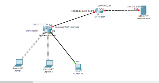
In our network set up, we have two laptops and a PC which should connect to a LAN provided by one wireless router.The PC is is used by the network Admin and connects to the LAN via an Ethernet port of wireless router.The laptops should connect to the same LAN by wireless means, and for this reason we’ll install wireless adapters on them. Still, we’ll need to connect the LAN to the internet via an ISP router.
Let’s now do all that step by step.
Wireless LAN configuration
First get into Cisco Packet Tracer and in the physical mode, pick a wireless router and two laptops,a PC, a generic server and a 2800-series router(or just any other router other than wireless).
Now connect the PC to the Ethernet 1 of the wireless router.
For the laptops, replace the already-installed wired LAN module with a wireless adapter module (WMP 300N) .
Make sure that you first power off each laptop before you make any replacement then restore the power back after replacement. That’s easy to do!
Once you have the wireless modules in place, you’ll see the wireless connections come up between the laptops and the wireless router as shown below.
Next, we’re going to do some settings on the wireless router to create a LAN then connect it to the internet.
To do any configuration on the wireless router, we’ll use its GUI(Graphical User Interface) which we can access either by:
- Clicking the Wireless Router icon then GUI tab, or
- Using a browser in a PC or laptop in the LAN.
Let’s use the PC to access the router GUI.
We’ll access the router from the PC or the laptops using the router’s LAN interface.The LAN interface is simply the default gateway of the LAN.
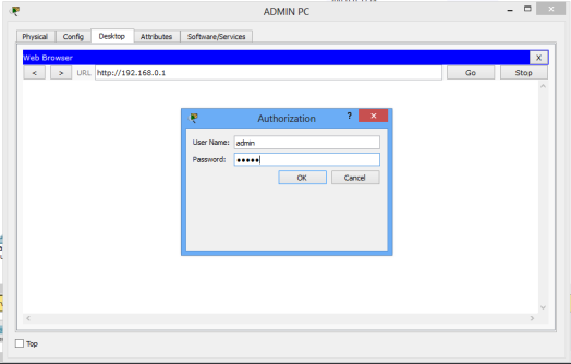
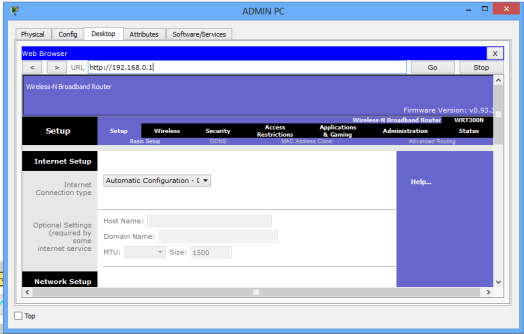
So now, on the ADMIN PC browser, type the IP address of the LAN interface of the wireless router.(192.168.0.1 by default ), then hit Go.
A login prompt appears. Provide the username (admin) and password (admin) to be allowed into the GUI of the router.You can always change these settings later.
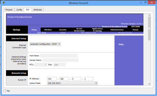
You should now be in the GUI of the router, whichever approach you chose to access it. Just examine it closely for a moment. On it, you can see several tabs like Setup, Wireless, Security, Access Restrictions, Application & Gaming, Administration and WRT 300N status.
For this tutorial we’ll focus on setup, wireless and administration tabs. Notice that once you click on one major tab, other ‘sub-tabs’ will appear.
Wireless Router Administration
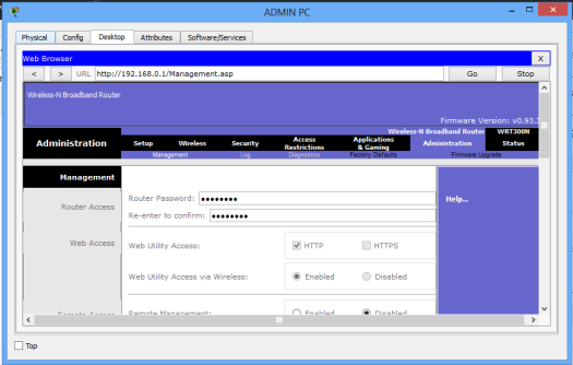
We’ll begin with Administration in the GUI. Here we’ll simply change the router’s username and password.
On the browser of Admin PC, type the IP address of the LAN interface of the wireless router(192.168.0.1, by default). Hit Go to access the GUI of the router. Provide the default username(admin) and password(admin). Click OK. You’re now on the GUI of the router. See it on the figure below.
Click on the Administration tab and set a new password for administrative access. Scroll down and Save settings. You will be prompted for a username and the new password you just set.Type them and click OK. Wait a bit. A new screen appears confirming settings are successful. You can click on continue to continue with configurations.
To test for the new password entered, close the browser of Admin PC and try to to access the GUI again using the browser. You’ll now provide the new password you’ve just set.
The admin username and password are important, as only a network admin(or a user with admin rights) is able to log into the router and manage its settings.
Let’s now move on to another setup.
LAN Setup and Internet Setup
To configure addresses for the LAN and internet connectivity, we’ll use Setup tab.
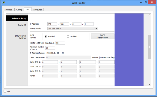
Network Setup
Network setup means LAN setup. Already, we have a PC and three laptops in the LAN.We’ll assign the them IP addresses either statically or dynamically (using a DHCP pool set up in the wireless router).
The default LAN network address given here is 192.168.0.0 with a subnet mask of 255.255.255.0 .The first address in this network (192.168.0.1 by default) has been assigned to the LAN interface of the router. It has just been named IP address. Obviously, all the PCs in the LAN will use the LAN interface as their default interface(to communicate to hosts in outside networks).
Now, in the router’s network settings, you may choose to enable DHCP to dynamically assign IP addresses to the PCs. On the other hand, if you choose to disable DHCP, then obviously, you’ll have to configure static IP addresses on the PCs.
When you choose to enable DHCP, set the start address for the LAN pool, maximum hosts to be allowed in your LAN and the DNS server for the LAN. The PCs will receive addresses automatically from the pool.
Now, going the DHCP way:
- Ensure DHCP is checked.
- Leave the IP address as 192.168.0.1 (This is the default LAN gateway address).
- Set a start address of 192.168.0.50 and set maximum users to 100 (or any number of users you want)
- You can leave the DNS server entry as it is (0.0.0.0) or specify the address of a DNS server of your choice.
- Scroll down and Save settings.
See the set up window below.
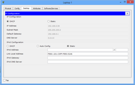
Moving on, let’s enable DHCP on each PC for dynamic configuration. Go to the IP configuration tab for each PC and enable DHCP. Each PC should automatically obtain an IP address from the router.
As an example, here is the IP configuration for Laptop1:
Now let’s test our wireless LAN.
Ping PC2 from PC1. Ping should succeed.
Try also to ping the LAN interface of the router from one of the PCs ,say, PC1 . It should be successful.
That was pretty easy! Let’s now move on and add wireless security for the wireless LAN access.
Adding security for wireless LAN access
The LAN network we have just setup has no wireless security features enabled. If this a was a production network, this would mean an obvious security threat since this makes the network accessible to unauthorized users. So let’s implement some level of wireless security to our LAN.
Access the GUI of wireless router (either by clicking on Router icon or from Admin PC browser), then click on Wireless tab. Under the Basic Wireless Settings sub tab, change the default wireless SSID to any name of your choice. I have named mine ‘myLAN‘. After this, don’t forget to Save settings.
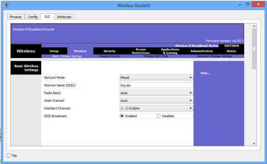
The acronym SSID stands for Service Set Identifier, and its the name of your wireless network(wireless LAN).
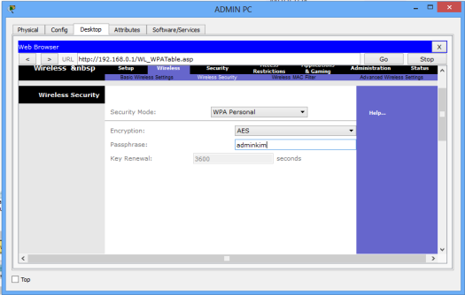
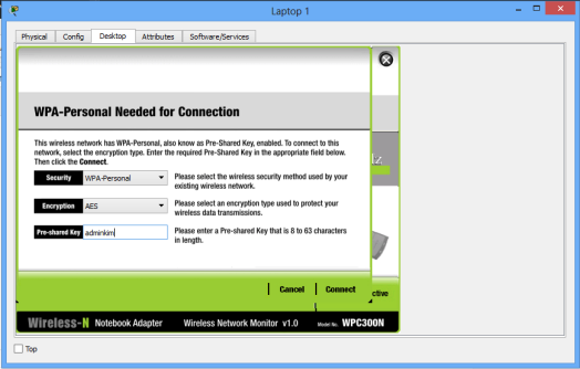
Still, in the Wireless tab, under the Wireless security sub tab, change security mode to WPA personal , then set passphrase field to a password of your choice. Scroll down and Save settings
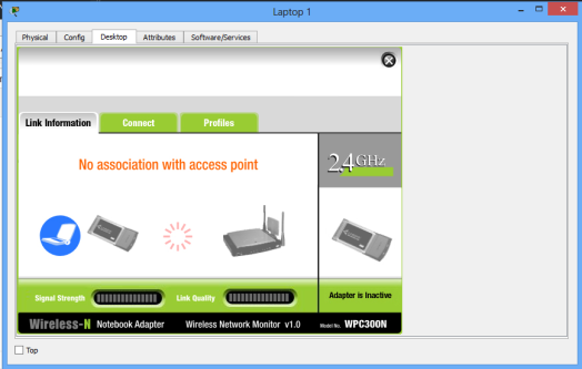
The LAN network is now secured for wireless access. To test whether its really protected, click Laptop1->Desktop->Wireless.
A new window appears that shows the now secured wireless network. Click connect. You can now see the name of the wireless network( myWIFI , in my case) and its signal strength. Site features listed include WPA1 PSK security feature.
Again, click connect, then provide the security pre-shared key for the WiFi that you set, then connect. Laptop 1 is now connected to the WiFi network. You can see at the bottom right of the screen that the wireless network adapter on the laptop is active.Repeat this process for the Laptop2.
Now, you can change the wireless security mode to any other from the available options. You may choose WEP security feature for our wireless network, for example. For WEP, provide a 40-bit (10 hexadecimal digits e.g. A123B456C789) or 64 -bit key(16 hex characters). WEP and WPA configurations look almost alike.
That’s all for wireless security configuration.
Lastly, let’s see how to set up internet configurations on the wireless Router so that the PC and laptops in the LAN can access the internet. So move on to the next section.
Internet Setup
For this part, we’ll configure the internet interface on the router so as to connect our LAN to the internet. Note that for different routers (from different vendors), the internet interface may be named differently; in some routers, for example, the interface may have the name ‘WAN interface‘, suitably because its the interface that allows devices in our LAN to access the internet.
Here, we’ll connect the internet interface to an ISP router which then connects to an internet server (example.com, as an example).
So now, access the Internet Setup tab on the GUI of the wireless router (either by clicking on its icon or from admin PC browser). Actually, in a real life router configuration, you’ll use a PC browser. In this case you should remember the username name and the new password you set.
To Set internet connectivity , we’ll need to set a static IP address on the interface or set interface as a DHCP client so that it will be assigned an address dynamically by the ISP router. Alternatively, you may use PPPoE to provide WAN connectivity to the internet.
Now, if you choose to configure a static IP address for the internet interface, you can specify also the default gateway and a DNS server of your choice.
And, if you’d rather like to have the internet interface address configured by DHCP, you’ll then set the internet interface as a DHCP client. A DHCP server will be configured on another device, such as the ISP router (in our topology here!).
Otherwise, if you choose PPPoE for internet connectivity, then set up the username and password for PPPoE authentication. The internet interface will then become a PPPoE client and will negotiate for connection with a PPPoE server running on an ISP device so as to achieve internet connectivity.Usually the username and password will be provided by your ISP.
For now, we’ll set the internet interface to act as a DHCP client (with the DHCP server configured on the ISP router)
So then :
First configure IP addresses and a DHCP server on ISP router.
ISP_ROUTER(config)#int fa0/0
ISP_ROUTER(config-if)#ip add 155.21.21.1 255.255.0.0
ISP_ROUTER(config-if)#no shut
ISP_ROUTER(config-if)#
ISP_ROUTER(config-if)#int fa0/1
ISP_ROUTER(config-if)#ip add 200.0.0.1 255.255.255.0
ISP_ROUTER(config-if)#no shut

ISP_ROUTER(config-if)#exit

ISP_ROUTER(config)#ip dhcp pool mypool
ISP_ROUTER(dhcp-config)#net 155.21.0.0 255.255.0.0
ISP_ROUTER(dhcp-config)#default-router 155.21.21.1
ISP_ROUTER(dhcp-config)#dns-server 0.0.0.0
Now make the internet interface a DHCP client by enabling DHCP on it.
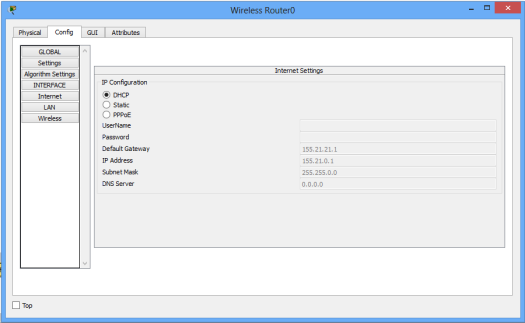
To verify DHCP configuration,click on the wireless router icon, then go to Config tab. Pick DHCP. The interface is now configured with an IP address from the pool set in the ISP router.
Next,we have to configure static or dynamic routes in the ISP router for the devices in the wireless LAN to gain access the internet server:
Here is a static route:
ISP_ROUTER(config)#ip route 192.168.0.0
                    255.255.255.0 fa0/0
Lastly, assign an IP address to the internet server (if you hadn’t done so), then try to reach the server from a host in the LAN.
For example, you can ping the server from Laptop1. Ping should succeed.
That’s all for this tutorial, and I hope you found the tutorial helpful. I also strongly believe that if you’ve gotten everything presented in here,then you have more than a foundation to create your own wireless network using a wireless router, e.g, home WiFi. It’s my believe!
Cheers!
See also:
- How to configure DHCP server in Packet Tracer.
- Configuring DHCPv6 (both stateless and stateful) in Packet Tracer.
- DNS server configuration in Packet Tracer
- IP helper-address configuration in Packet Tracer