Implementing IPv6 Addressing and Basic Connectivity
Implementing basic IPv6 connectivity in the Cisco IOS software consists of assigning IPv6 addresses to individual router
interfaces. The forwarding of IPv6 traffic can be enabled globally, and Cisco Express Forwarding switching for IPv6 can also
be enabled. Basic connectivity can be enhanced by configuring support for AAAA record types in the Domain Name System (DNS)
name-to-address and address-to-name lookup processes, and by managing IPv6 neighbor discovery.
Finding Feature Information
Your software release may not support all the features documented in this module. For the latest caveats and feature information,
see Bug Search Tooland the release notes for your platform and software release. To find information about the features documented in this module,
and to see a list of the releases in which each feature is supported, see the feature information table.
Use Cisco Feature Navigator to find information about platform support and Cisco software image support. To access Cisco Feature
Navigator, go to www.cisco.com/go/cfn. An account on Cisco.com is not required.
Prerequisites for Implementing IPv6 Addressing and Basic Connectivity
-
The following prerequisites apply to Cisco Express Forwarding and distributed Cisco Express Forwarding for IPv6: - To forward IPv6 traffic using Cisco Express Forwarding or distributed Cisco Express Forwarding, you must configure forwarding
of IPv6 unicast datagrams globally on the router by using the
ipv6 unicast-routing command, and you must configure an IPv6 address on an interface by using the
ipv6 address command. - You must enable Cisco Express Forwarding for IPv4 globally on the router by using the
ip
cef command before enabling Cisco Express Forwarding for IPv6 globally on the router by using the
ipv6
cef command. - On distributed architecture platforms that support both Cisco Express Forwarding and distributed Cisco Express Forwarding,
you must enable distributed Cisco Express Forwarding for IPv4 globally on the router by using the
ip
cef
distributed command before enabling distributed Cisco Express Forwarding for IPv6 globally on the router by using the
ipv6
cef
distributed command. - To use Unicast Reverse Path Forwarding (RPF), enable Cisco Express Forwarding switching or distributed Cisco Express Forwarding
switching in the router. There is no need to configure the input interface for Cisco Express Forwarding switching. As long
as Cisco Express Forwarding is running on the router, individual interfaces can be configured with other switching modes.
Note
For Unicast RPF to work, Cisco Express Forwarding must be configured globally in the router. Unicast RPF will not work without
Cisco Express Forwarding.
- To forward IPv6 traffic using Cisco Express Forwarding or distributed Cisco Express Forwarding, you must configure forwarding
Restrictions for Implementing
IPv6 Addressing and Basic Connectivity
-
Multiple IPv6
global addresses within the same prefix can be configured on an interface;
however, multiple IPv6 link-local addresses on an interface are not supported. -
IPv4 alias and IPv6 alias addresses used must be available in the global routing table and not under VRF.
Information About Implementing IPv6 Addressing and Basic Connectivity
IPv6 for Cisco Software
IPv6, formerly named IPng (next generation), is the latest version of the Internet Protocol (IP). IP is a packet-based protocol
used to exchange data, voice, and video traffic over digital networks. IPv6 was proposed when it became clear that the 32-bit
addressing scheme of IP version 4 (IPv4) was inadequate to meet the demands of Internet growth. After extensive discussion
it was decided to base IPng on IP but add a much larger address space and improvements such as a simplified main header and
extension headers. IPv6 is described initially in RFC 2460,
Internet Protocol, Version 6 (IPv6) Specification, issued by the Internet Engineering Task Force (IETF). Further RFCs describe the architecture and services supported by IPv6.
The architecture of IPv6 has been designed to allow existing IPv4 users to transition easily to IPv6 while providing services
such as end-to-end security, quality of service (QoS), and globally unique addresses. The larger IPv6 address space allows
networks to scale and provide global reachability. The simplified IPv6 packet header format handles packets more efficiently.
IPv6 prefix aggregation, simplified network renumbering, and IPv6 site multihoming capabilities provide an IPv6 addressing
hierarchy that allows for more efficient routing. IPv6 supports widely deployed routing protocols such as Routing Information
Protocol (RIP), Integrated Intermediate System-to-Intermediate System (IS-IS), Open Shortest Path First (OSPF) for IPv6, and
multiprotocol Border Gateway Protocol (BGP). Other available features include stateless autoconfiguration and an increased
number of multicast addresses.
Large IPv6 Address Space for Unique Addresses
The primary motivation for IPv6 is the need to meet the demand for globally unique IP addresses. IPv6 quadruples the number
of network address bits from 32 bits (in IPv4) to 128 bits, which provides more than enough globally unique IP addresses for
every networked device on the planet. By being globally unique, IPv6 addresses inherently enable global reachability and end-to-end
security for networked devices, functionality that is crucial to the applications and services that are driving the demand
for the addresses. Additionally, the flexibility of the IPv6 address space reduces the need for private addresses; therefore,
IPv6 enables new application protocols that do not require special processing by border devices at the edge of networks.
IPv6 Address Formats
IPv6 addresses are represented as a series of 16-bit hexadecimal fields separated by colons (:) in the format: x:x:x:x:x:x:x:x.
Following are two examples of IPv6 addresses:
2001:DB8:7654:3210:FEDC:BA98:7654:3210
2001:DB8:0:0:8:800:200C:417A
IPv6 addresses commonly contain successive hexadecimal fields of zeros. Two colons (::) may be used to compress successive
hexadecimal fields of zeros at the beginning, middle, or end of an IPv6 address (the colons represent successive hexadecimal
fields of zeros). The table below lists compressed IPv6 address formats.
A double colon may be used as part of the
ipv6-address argument when consecutive 16-bit values are denoted as zero. You can configure multiple IPv6 addresses per interfaces, but
only one link-local address.
 Note |
Two colons (::) can be used only once in an IPv6 address to represent the longest successive hexadecimal fields of zeros. |
|
IPv6 Address Type |
Preferred Format |
Compressed Format |
|---|---|---|
|
Unicast |
2001:0:0:0:DB8:800:200C:417A |
2001::DB8:800:200C:417A |
|
Multicast |
FF01:0:0:0:0:0:0:101 |
FF01::101 |
|
Loopback |
0:0:0:0:0:0:0:1 |
::1 |
|
Unspecified |
0:0:0:0:0:0:0:0 |
:: |
The loopback address listed in the table above may be used by a node to send an IPv6 packet to itself. The loopback address
in IPv6 functions the same as the loopback address in IPv4 (127.0.0.1).
Note |
The IPv6 loopback address cannot be assigned to a physical interface. A packet that has the IPv6 loopback address as its |
The unspecified address listed in the table above indicates the absence of an IPv6 address. For example, a newly initialized
node on an IPv6 network may use the unspecified address as the source address in its packets until it receives its IPv6 address.
Note |
The IPv6 unspecified address cannot be assigned to an interface. The unspecified IPv6 addresses must not be used as destination |
An IPv6 address prefix, in the format
ipv6-prefix /prefix-length , can be used to represent bit-wise contiguous blocks of the entire address space. The
ipv6-prefix must be in the form documented in RFC 2373 where the address is specified in hexadecimal using 16-bit values between colons.
The prefix length is a decimal value that indicates how many of the high-order contiguous bits of the address comprise the
prefix (the network portion of the address). For example, 2001:DB8:8086:6502::/32 is a valid IPv6 prefix.
IPv6 Address Type: Unicast
An IPv6 unicast address is an identifier for a single interface, on a single node. A packet that is sent to a unicast address
is delivered to the interface identified by that address. Cisco software supports the IPv6 unicast address types described
in the following sections.
Aggregatable Global Address
An aggregatable global address is an IPv6 address from the aggregatable global unicast prefix. The structure of aggregatable
global unicast addresses enables strict aggregation of routing prefixes that limits the number of routing table entries in
the global routing table. Aggregatable global addresses are used on links that are aggregated upward through organizations,
and eventually to the Internet service providers (ISPs).
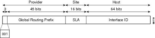
Aggregatable global IPv6 addresses are defined by a global routing prefix, a subnet ID, and an interface ID. Except for addresses
that start with binary 000, all global unicast addresses have a 64-bit interface ID. The IPv6 global unicast address allocation
uses the range of addresses that start with binary value 001 (2000::/3). The figure below shows the structure of an aggregatable
global address.
Addresses with a prefix of 2000::/3 (001) through E000::/3 (111) are required to have 64-bit interface identifiers in the
extended universal identifier (EUI)-64 format. The Internet Assigned Numbers Authority (IANA) allocates the IPv6 address space
in the range of 2000::/16 to regional registries.
The aggregatable global address typically consists of a 48-bit global routing prefix and a 16-bit subnet ID or Site-Level
Aggregator (SLA). In the IPv6 aggregatable global unicast address format document (RFC 2374), the global routing prefix included
two other hierarchically structured fields named Top-Level Aggregator (TLA) and Next-Level Aggregator (NLA). The IETF decided
to remove the TLS and NLA fields from the RFCs because these fields are policy-based. Some existing IPv6 networks deployed
before the change might still be using networks based on the older architecture.
A 16-bit subnet field called the subnet ID could be used by individual organizations to create their own local addressing
hierarchy and to identify subnets. A subnet ID is similar to a subnet in IPv4, except that an organization with an IPv6 subnet
ID can support up to 65,535 individual subnets.
An interface ID is used to identify interfaces on a link. The interface ID must be unique to the link. It may also be unique
over a broader scope. In many cases, an interface ID will be the same as or based on the link-layer address of an interface.
Interface IDs used in aggregatable global unicast and other IPv6 address types must be 64 bits long and constructed in the
modified EUI-64 format.
Interface IDs are constructed in the modified EUI-64 format in one of the following ways:
-
For all IEEE 802 interface types (for example, FDDI interfaces), the first three octets (24 bits) are taken from the Organizationally
Unique Identifier (OUI) of the 48-bit link-layer address (the Media Access Control [MAC] address) of the interface, the fourth
and fifth octets (16 bits) are a fixed hexadecimal value of FFFE, and the last three octets (24 bits) are taken from the last
three octets of the MAC address. The construction of the interface ID is completed by setting the Universal/Local (U/L) bit—the
seventh bit of the first octet—to a value of 0 or 1. A value of 0 indicates a locally administered identifier; a value of
1 indicates a globally unique IPv6 interface identifier. -
For all other interface types (for example, serial, loopback, ATM, Frame Relay, and tunnel interface types—except tunnel
interfaces used with IPv6 overlay tunnels), the interface ID is constructed in the same way as the interface ID for IEEE 802
interface types; however, the first MAC address from the pool of MAC addresses in the router is used to construct the identifier
(because the interface does not have a MAC address). -
For tunnel interface types that are used with IPv6 overlay tunnels, the interface ID is the IPv4 address assigned to the
tunnel interface with all zeros in the high-order 32 bits of the identifier.
Note |
For interfaces using Point-to-Point Protocol (PPP), given that the interfaces at both ends of the connection might have the |
If no IEEE 802 interface types are in the router, link-local IPv6 addresses are generated on the interfaces in the router
in the following sequence:
-
The router is queried for MAC addresses (from the pool of MAC addresses in the router).
-
If no MAC addresses are available in the router, the serial number of the router is used to form the link-local addresses.
-
If the serial number of the router cannot be used to form the link-local addresses, the router uses a message digest algorithm
5 (MD5) hash to determine the MAC address of the router from the hostname of the router.
Link-Local Address
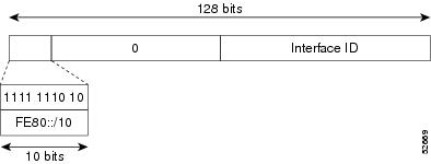
A link-local address is an IPv6 unicast address that can be automatically configured on any interface using the link-local
prefix FE80::/10 (1111 1110 10) and the interface identifier in the modified EUI-64 format. Link-local addresses are used
in the neighbor discovery protocol and the stateless autoconfiguration process. Nodes on a local link can use link-local addresses
to communicate; the nodes do not need globally unique addresses to communicate. The figure below shows the structure of a
link-local address.
IPv6 devices must not forward packets that have link-local source or destination addresses to other links.
IPv4-Compatible IPv6 Address
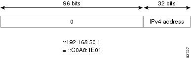
An IPv4-compatible IPv6 address is an IPv6 unicast address that has zeros in the high-order 96 bits of the address and an
IPv4 address in the low-order 32 bits of the address. The format of an IPv4-compatible IPv6 address is 0:0:0:0:0:0:A.B.C.D
or ::A.B.C.D. The entire 128-bit IPv4-compatible IPv6 address is used as the IPv6 address of a node and the IPv4 address embedded
in the low-order 32 bits is used as the IPv4 address of the node. IPv4-compatible IPv6 addresses are assigned to nodes that
support both the IPv4 and IPv6 protocol stacks and are used in automatic tunnels. The figure below shows the structure of
an IPv4-compatible IPv6 address and a few acceptable formats for the address.
IPv6 Address Type Multicast
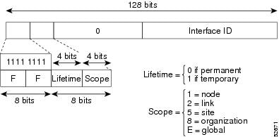
An IPv6 multicast address is an IPv6 address that has a prefix of FF00::/8 (1111 1111). An IPv6 multicast address is an identifier
for a set of interfaces that typically belong to different nodes. A packet sent to a multicast address is delivered to all
interfaces identified by the multicast address. The second octet following the prefix defines the lifetime and scope of the
multicast address. A permanent multicast address has a lifetime parameter equal to 0; a temporary multicast address has a
lifetime parameter equal to 1. A multicast address that has the scope of a node, link, site, or organization, or a global
scope has a scope parameter of 1, 2, 5, 8, or E, respectively. For example, a multicast address with the prefix FF02::/16
is a permanent multicast address with a link scope. The figure below shows the format of the IPv6 multicast address.
An IPv6 address must be configured on an interface for the interface to forward IPv6 traffic. Configuring a global IPv6 address
on an interface automatically configures a link-local address and activates IPv6 for that interface. Additionally, the configured
interface automatically joins the following required multicast groups for that link:
-
Solicited-node multicast group FF02:0:0:0:0:1:FF00::/104 for each unicast address assigned to the interface
-
All-nodes link-local multicast group FF02::1
-
All-routers link-local multicast group FF02::2
Note |
The solicited-node multicast address is used in the Neighbor Discovery process. |
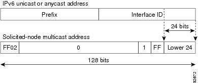
The solicited-node multicast address is a multicast group that corresponds to an IPv6 unicast address. IPv6 nodes must join
the associated solicited-node multicast group for every unicast address to which it is assigned. The IPv6 solicited-node multicast
address has the prefix FF02:0:0:0:0:1:FF00:0000/104 concatenated with the 24 low-order bits of a corresponding IPv6 unicast
address (see the figure below). For example, the solicited-node multicast address corresponding to the IPv6 address 2037::01:800:200E:8C6C
is FF02::1:FF0E:8C6C. Solicited-node addresses are used in neighbor solicitation messages.
Note |
There are no broadcast addresses in IPv6. IPv6 multicast addresses are used instead of broadcast addresses. |
IPv6 Address Output Display
When IPv6 or IPv4 command output displays an IPv6 address, a long IPv6 address can overflow into neighboring fields, causing
the output to be difficult to read. The output fields were designed to work with the longest possible IPv4 address, which
has 15 characters; IPv6 addresses can be up to 39 characters long. The following scheme has been adopted in IPv4 and IPv6
commands to allow the appropriate length of IPv6 address to be displayed and move the following fields to the next line, if
necessary. The fields that are moved are kept in alignment with the header row.
The following example displays eight connections. The first six connections feature IPv6 addresses; the last two connections
feature IPv4 addresses.
Device# where
Conn Host                Address             Byte  Idle Conn Name
   1 test5               2001:DB8:3333:4::5    6    24 test5
   2 test4               2001:DB8:3333:44::5
                                               6    24 test4
   3 2001:DB8:3333:4::5 2001:DB8:3333:4::5     6    24 2001:DB8:3333:4::5
   4 2001:DB8:3333:44::5
                         2001:DB8:3333:44::5
                                               6    23 2001:DB8:3333:44::5
   5 2001:DB8:3000:4000:5000:6000:7000:8001
                         2001:DB8:3000:4000:5000:6000:7000:8001
                                               6    20 2001:DB8:3000:4000:5000:6000:
   6 2001:DB8:1::1      2001:DB8:1::1          0     1 2001:DB8:1::1
   7 10.1.9.1            10.1.9.1              0     0 10.1.9.1
   8 10.222.111.222      10.222.111.222        0     0 10.222.111.222
Connection 1 contains an IPv6 address that uses the maximum address length in the address field. Connection 2 shows the IPv6
address overflowing the address field and the following fields moved to the next line, but in alignment with the appropriate
headers. Connection 3 contains an IPv6 address that fills the maximum length of the hostname and address fields without wrapping
any lines. Connection 4 shows the effect of both the hostname and address fields containing a long IPv6 address. The output
is shown over three lines keeping the correct heading alignment. Connection 5 displays a similar effect as connection 4 with
a very long IPv6 address in the hostname and address fields. Note that the connection name field is actually truncated. Connection
6 displays a very short IPv6 address that does not require any change in the display. Connections 7 and 8 display short and
long IPv4 addresses.
Note |
The IPv6 address output display applies to all commands that display IPv6 addresses. |
Simplified IPv6 Packet Header
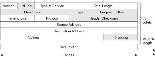
The basic IPv4 packet header has 12 fields with a total size of 20 octets (160 bits) (see the figure below). The 12 fields
may be followed by an Options field, which is followed by a data portion that is usually the transport-layer packet. The variable
length of the Options field adds to the total size of the IPv4 packet header. The shaded fields of the IPv4 packet header
shown in the figure below are not included in the IPv6 packet header.
The basic IPv6 packet header has 8 fields with a total size of 40 octets (320 bits) (see the figure below). Fields were removed
from the IPv6 header because, in IPv6, fragmentation is not handled by devices and checksums at the network layer are not
used. Instead, fragmentation in IPv6 is handled by the source of a packet and checksums at the data link layer and transport
layer are used. (In IPv4, the UDP transport layer uses an optional checksum. In IPv6, use of the UDP checksum is required
to check the integrity of the inner packet.) Additionally, the basic IPv6 packet header and Options field are aligned to 64
bits, which can facilitate the processing of IPv6 packets.

The table below lists the fields in the basic IPv6 packet header.
|
Field |
Description |
|---|---|
|
Version |
Similar to the Version field in the IPv4 packet header, except that the field lists number 6 for IPv6 instead of number 4 |
|
Traffic Class |
Similar to the Type of Service field in the IPv4 packet header. The Traffic Class field tags packets with a traffic class |
|
Flow Label |
A new field in the IPv6 packet header. The Flow Label field tags packets with a specific flow that differentiates the packets |
|
Payload Length |
Similar to the Total Length field in the IPv4 packet header. The Payload Length field indicates the total length of the data |
|
Next Header |
Similar to the Protocol field in the IPv4 packet header. The value of the Next Header field determines the type of information |
|
Hop Limit |
Similar to the Time to Live field in the IPv4 packet header. The value of the Hop Limit field specifies the maximum number |
|
Source Address |
Similar to the Source Address field in the IPv4 packet header, except that the field contains a 128-bit source address for |
|
Destination Address |
Similar to the Destination Address field in the IPv4 packet header, except that the field contains a 128-bit destination |
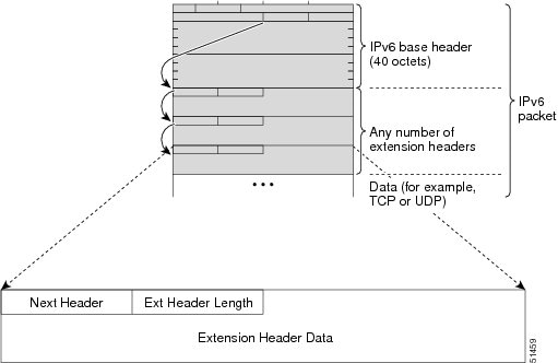
Following the eight fields of the basic IPv6 packet header are optional extension headers and the data portion of the packet.
If present, each extension header is aligned to 64 bits. There is no fixed number of extension headers in an IPv6 packet.
The extension headers form a chain of headers. Each extension header is identified by the Next Header field of the previous
header. Typically, the final extension header has a Next Header field of a transport-layer protocol, such as TCP or UDP. The
figure below shows the IPv6 extension header format.
The table below lists the extension header types and their Next Header field values.
|
Header Type |
Next Header Value |
Description |
|---|---|---|
|
Hop-by-hop options header |
0 |
This header is processed by all hops in the path of a packet. When present, the hop-by-hop options header always follows |
|
Destination options header |
60 |
The destination options header can follow any hop-by-hop options header, in which case the destination options header is |
|
Routing header |
43 |
The routing header is used for source routing. |
|
Fragment header |
44 |
The fragment header is used when a source must fragment a packet that is larger than the maximum transmission unit (MTU) |
|
Authentication header and ESP header |
51 50 |
The Authentication header and the ESP header are used within IP Security Protocol (IPsec) to provide authentication, integrity, |
|
Upper-layer headers |
6 (TCP) 17 (UDP) |
The upper-layer (transport) headers are the typical headers used inside a packet to transport the data. The two main transport |
|
Mobility headers |
135 |
Extension headers used by mobile nodes, correspondent nodes, and home agents in all messaging related to the creation and |
Cisco Express Forwarding
for IPv6
Cisco Express
Forwarding is advanced, Layer 3 IP switching technology for the forwarding of
IPv6 packets.
Each IPv6 router
interface has an association to one IPv6 global FIB and one IPv6 link-local FIB
(multiple interfaces can have an association to the same FIB). All IPv6 router
interfaces that are attached to the same IPv6 link share the same IPv6
link-local FIB. IPv6 packets that have an IPv6 global destination address are
processed by the IPv6 global FIB; however, packets that have an IPv6 global
destination address and an IPv6 link-local source address are sent to the RP
for process switching and scope-error handling. Packets that have a link-local
source address are not forwarded off of the local link and are sent to the RP
for process switching and scope-error handling.
Unicast Reverse Path
Forwarding
Use the Unicast
Reverse Path Forwarding for IPv6 feature to mitigate problems caused by
malformed or spoofed IPv6 source addresses that pass through an IPv6 device.
Malformed or forged source addresses can indicate denial-of-service (DoS)
attacks based on source IPv6 address spoofing.
When uRPF is enabled
on an interface, the device examines all packets received on that interface.
The device verifies that the source address appears in the routing table and
matches the interface on which the packet was received. This «look backward»
ability is available only when Cisco Express Forwarding is enabled on the
device; this is because the lookup relies on the presence of the Forwarding
Information Bases (FIBs). Cisco Express Forwarding generates the FIB as part of
its operation.
Note |
uRPF is an input |
Note |
With uRPF, all |
DNS for IPv6
IPv6 supports DNS record types that are supported in the DNS name-to-address and address-to-name lookup processes. The DNS
record types support IPv6 addresses. IPv6 also supports the reverse mapping of IPv6 addresses to DNS names.
The table below lists the IPv6 DNS record types.
|
Record Type |
Description |
Format |
||
|---|---|---|---|---|
|
AAAA |
Maps a hostname to an IPv6 address. (Equivalent to an A record in IPv4.) |
www.abc.test AAAA 3FFE:YYYY:C18:1::2 |
||
|
PTR |
Maps an IPv6 address to a hostname. (Equivalent to a PTR record in IPv4.)
|
2.0.0.0.0.0.0.0.0.0.0.0.0.0.0.0.1.0.0.0.8.1.c.0.y.y.y.y.e.f.f.3.ip6.int PTR www.abc.test |
Cisco Discovery Protocol IPv6 Address Support
The Cisco Discovery Protocol IPv6 address support for neighbor information feature adds the ability to transfer IPv6 addressing
information between two Cisco devices. Cisco Discovery Protocol support for IPv6 addresses provides IPv6 information to network
management products and troubleshooting tools.
ICMP for IPv6
Internet Control Message Protocol (ICMP) in IPv6 functions the same as ICMP in IPv4. ICMP generates error messages, such
as ICMP destination unreachable messages, and informational messages, such as ICMP echo request and reply messages. Additionally,
ICMP packets in IPv6 are used in the IPv6 neighbor discovery process, path MTU discovery, and the Multicast Listener Discovery
(MLD) protocol for IPv6. MLD is used by IPv6 devices to discover multicast listeners (nodes that want to receive multicast
packets destined for specific multicast addresses) on directly attached links. MLD is based on version 2 of the Internet Group
Management Protocol (IGMP) for IPv4.
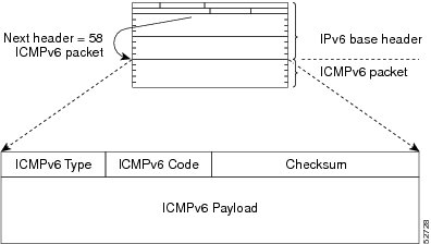
A value of 58 in the Next Header field of the basic IPv6 packet header identifies an IPv6 ICMP packet. ICMP packets in IPv6
are like a transport-layer packet in the sense that the ICMP packet follows all the extension headers and is the last piece
of information in the IPv6 packet. Within IPv6 ICMP packets, the ICMPv6 Type and ICMPv6 Code fields identify IPv6 ICMP packet
specifics, such as the ICMP message type. The value in the Checksum field is derived (computed by the sender and checked by
the receiver) from the fields in the IPv6 ICMP packet and the IPv6 pseudoheader. The ICMPv6 Data field contains error or diagnostic
information relevant to IP packet processing. The figure below shows the IPv6 ICMP packet header format.
IPv6 ICMP Rate Limiting
The IPv6 ICMP rate limiting feature implements a token bucket algorithm for limiting the rate at which IPv6 ICMP error messages
are sent out on the network. The initial implementation of IPv6 ICMP rate limiting defined a fixed interval between error
messages, but some applications such as traceroute often require replies to a group of requests sent in rapid succession.
The fixed interval between error messages is not flexible enough to work with applications such as traceroute and can cause
the application to fail.
Implementing a token bucket scheme allows a number of tokens—representing the ability to send one error message each—to
be stored in a virtual bucket. The maximum number of tokens allowed in the bucket can be specified, and for every error message
to be sent, one token is removed from the bucket. If a series of error messages is generated, error messages can be sent until
the bucket is empty. When the bucket is empty of tokens, no IPv6 ICMP error messages are sent until a new token is placed
in the bucket. The token bucket algorithm does not increase the average rate limiting time interval, and it is more flexible
than the fixed time interval scheme.
IPv6 MTU Path Discovery
As in IPv4, path MTU discovery in IPv6 allows a host to dynamically discover and adjust to differences in the MTU size of
every link along a given data path. In IPv6, however, fragmentation is handled by the source of a packet when the path MTU
of one link along a given data path is not large enough to accommodate the size of the packets. Having IPv6 hosts handle packet
fragmentation saves IPv6 device processing resources and helps IPv6 networks run more efficiently.
Note |
In IPv6, the minimum link MTU is 1280 octets. We recommend using an MTU value of 1500 octets for IPv6 links. |
With IPv6 path MTU discovery, a device originating IPv6 traffic has an MTU cache that contains MTU values received in ICMPv6
«toobig» messages. In order to prevent an attacker from filling the MTU cache, the device keeps track of the destinations
to which it has originated (sent) traffic, and only accepts toobig ICMPv6 messages that have an inner destination matching
one of these tracked destinations.
If a malicious device can learn to which destination the device is originating traffic, it could still send a toobig ICMPv6
message to the device for this destination, even if the attacker is not on the path to this destination, and succeeds in forcing
his entry into the MTU cache. The device then starts fragmenting traffic to this destination, which significantly affects
device performance.
Enabling flow-label marking for locally generated traffic can mitigate this attack. Originated packets are marked with a
flow label (which is randomly generated and changed every minute), and toobig messages received are checked against the values
sent. Unless an attacker can snoop traffic, the attacker will not know which flow label to use, and its toobig message will
be dropped.
IPv6 Neighbor Discovery
The IPv6 neighbor discovery process uses ICMP messages and solicited-node multicast addresses to determine the link-layer
address of a neighbor on the same network (local link), verify the reachability of a neighbor, and track neighboring devices.
The IPv6 static cache entry for neighbor discovery feature allows static entries to be made in the IPv6 neighbor cache. Static
routing requires an administrator to manually enter IPv6 addresses, subnet masks, gateways, and corresponding Media Access
Control (MAC) addresses for each interface of each device into a table. Static routing enables more control but requires more
work to maintain the table. The table must be updated each time routes are added or changed.
Stateful Switchover
IPv6 neighbor discovery supports stateful switchover (SSO) using Cisco Express Forwarding. When switchover occurs, the Cisco
Express Forwarding adjacency state, which is checkpointed, is used to reconstruct the neighbor discovery cache.
SSO and ISSU Support for Per-User IPv6 ACL for PPP Sessions
The Stateful Switchover (SSO) and In Service Software Upgrade (ISSU) support for per-user IPv6 ACL for PPP sessions feature
reproduces IPv6 ACLs on the active RP to the standby RP, which provide a consistent SSO and ISSU experience for active sessions.
IPv6 Neighbor Solicitation Message
A value of 135 in the Type field of the ICMP packet header identifies a neighbor solicitation message. Neighbor solicitation
messages are sent on the local link when a node wants to determine the link-layer address of another node on the same local
link (see the figure below). When a node wants to determine the link-layer address of another node, the source address in
a neighbor solicitation message is the IPv6 address of the node sending the neighbor solicitation message. The destination
address in the neighbor solicitation message is the solicited-node multicast address that corresponds to the IPv6 address
of the destination node. The neighbor solicitation message also includes the link-layer address of the source node.
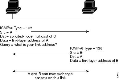
After receiving the neighbor solicitation message, the destination node replies by sending a neighbor advertisement message,
which has a value of 136 in the Type field of the ICMP packet header, on the local link. The source address in the neighbor
advertisement message is the IPv6 address of the node (more specifically, the IPv6 address of the node interface) sending
the neighbor advertisement message. The destination address in the neighbor advertisement message is the IPv6 address of the
node that sent the neighbor solicitation message. The data portion of the neighbor advertisement message includes the link-layer
address of the node sending the neighbor advertisement message.
After the source node receives the neighbor advertisement, the source node and destination node can communicate.
Neighbor solicitation messages are also used to verify the reachability of a neighbor after the link-layer address of a neighbor
is identified. When a node wants to verify the reachability of a neighbor, the destination address in a neighbor solicitation
message is the unicast address of the neighbor.
Neighbor advertisement messages are also sent when there is a change in the link-layer address of a node on a local link.
When there is such a change, the destination address for the neighbor advertisement is the all-nodes multicast address.
Neighbor solicitation messages are also used to verify the reachability of a neighbor after the link-layer address of a neighbor
is identified. Neighbor unreachability detection identifies the failure of a neighbor or the failure of the forward path to
the neighbor, and is used for all paths between hosts and neighboring nodes (hosts or devices). Neighbor unreachability detection
is performed for neighbors to which only unicast packets are being sent and is not performed for neighbors to which multicast
packets are being sent.
A neighbor is considered reachable when a positive acknowledgment is returned from the neighbor (indicating that packets
previously sent to the neighbor have been received and processed). A positive acknowledgment from an upper-layer protocol
(such as TCP) indicates that a connection is making forward progress (reaching its destination) or the receipt of a neighbor
advertisement message in response to a neighbor solicitation message. If packets are reaching the peer, they are also reaching
the next-hop neighbor of the source. Therefore, forward progress is also a confirmation that the next-hop neighbor is reachable.
For destinations that are not on the local link, forward progress implies that the first-hop device is reachable. When acknowledgments
from an upper-layer protocol are not available, a node probes the neighbor using unicast neighbor solicitation messages to
verify that the forward path is still working.
The return of a solicited neighbor advertisement message from the neighbor is a positive acknowledgment that the forward
path is still working (neighbor advertisement messages that have the solicited flag set to a value of 1 are sent only in response
to a neighbor solicitation message). Unsolicited messages confirm only the one-way path from the source to the destination
node; solicited neighbor advertisement messages indicate that a path is working in both directions.
Note |
A neighbor advertisement message that has the solicited flag set to a value of 0 must not be considered as a positive acknowledgment |
Neighbor solicitation messages are also used in the stateless autoconfiguration process to verify the uniqueness of unicast
IPv6 addresses before the addresses are assigned to an interface. Duplicate address detection is performed first on a new,
link-local IPv6 address before the address is assigned to an interface (the new address remains in a tentative state while
duplicate address detection is performed). Specifically, a node sends a neighbor solicitation message with an unspecified
source address and a tentative link-local address in the body of the message. If another node is already using that address,
the node returns a neighbor advertisement message that contains the tentative link-local address. If another node is simultaneously
verifying the uniqueness of the same address, that node also returns a neighbor solicitation message. If no neighbor advertisement
messages are received in response to the neighbor solicitation message and no neighbor solicitation messages are received
from other nodes that are attempting to verify the same tentative address, the node that sent the original neighbor solicitation
message considers the tentative link-local address to be unique and assigns the address to the interface.
Every IPv6 unicast address (global or link-local) must be verified for uniqueness on the link; however, until the uniqueness
of the link-local address is verified, duplicate address detection is not performed on any other IPv6 addresses associated
with the link-local address. The Cisco implementation of duplicate address detection in the Cisco software does not verify
the uniqueness of anycast or global addresses that are generated from 64-bit interface identifiers.
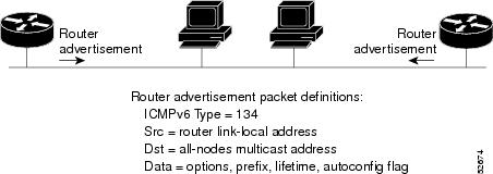
IPv6 Router Advertisement
Message
Router advertisement
(RA) messages, which have a value of 134 in the Type field of the ICMP packet
header, are periodically sent out each configured interface of an IPv6 router.
For stateless autoconfiguration to work properly, the advertised prefix length
in RA messages must always be 64 bits.
The RA messages are
sent to the all-nodes multicast address (see the figure below).
Message
RA messages typically
include the following information:
-
One or more
onlink IPv6 prefixes that nodes on the local link can use to automatically
configure their IPv6 addresses -
Lifetime
information for each prefix included in the advertisement -
Sets of flags
that indicate the type of autoconfiguration (stateless or stateful) that can be
completed -
Default router
information (whether the router sending the advertisement should be used as a
default router and, if so, the amount of time (in seconds) the router should be
used as a default router) -
Additional
information for hosts, such as the hop limit and MTU a host should use in
packets that it originates
RAs are also sent in
response to router solicitation messages.
The following RA
message parameters can be configured:
-
The time interval
between periodic RA messages -
The «router
lifetime» value, which indicates the usefulness of a router as the default
router (for use by all nodes on a given link) -
The network
prefixes in use on a given link -
The time interval
between neighbor solicitation message retransmissions (on a given link) -
The amount of
time a node considers a neighbor reachable (for use by all nodes on a given
link)
The configured
parameters are specific to an interface. The sending of RA messages (with
default values) is automatically enabled on FDDI interfaces when the
ipv6
unicast-routing command is configured. For other
interface types, the sending of RA messages must be manually configured by
using the
no
ipv6
nd
ra
suppress command. The sending of RA messages can be
disabled on individual interfaces by using the
ipv6
nd
ra suppress command.
Default Router Preferences for Traffic Engineering
Hosts discover and select default devices by listening to router advertisements (RAs). Typical default device selection mechanisms
are suboptimal in certain cases, such as when traffic engineering is needed. For example, two devices on a link may provide
equivalent but not equal-cost routing, and policy may dictate that one of the devices is preferred. Some examples are as follows:
-
Multiple devices that route to distinct sets of prefixes—Redirects (sent by nonoptimal devices for a destination) mean that
hosts can choose any device and the system will work. However, traffic patterns may mean that choosing one of the devices
would lead to considerably fewer redirects. -
Accidentally deploying a new device—Deploying a new device before it has been fully configured could lead to hosts adopting
the new device as a default device and traffic disappearing. Network managers may want to indicate that some devices are more
preferred than others. -
Multihomed situations—Multihomed situations may become more common, because of multiple physical links and because of the
use of tunneling for IPv6 transport. Some of the devices may not provide full default routing because they route only to the
6-to-4 prefix or they route only to a corporate intranet. These situations cannot be resolved with redirects, which operate
only over a single link.
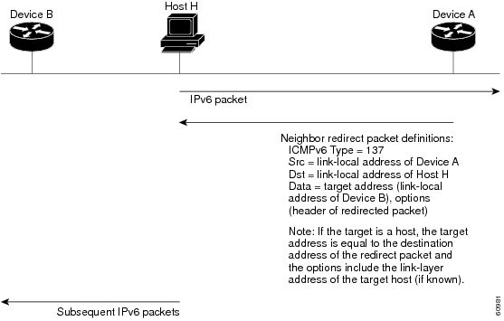
IPv6 Neighbor Redirect Message
A value of 137 in the type field of the ICMP packet header identifies an IPv6 neighbor redirect message. Devices send neighbor
redirect messages to inform hosts of better first-hop nodes on the path to a destination (see the figure below).
Note |
A device must be able to determine the link-local address for each of its neighboring devices in order to ensure that the |
After forwarding a packet, a device should send a redirect message to the source of the packet under the following circumstances:
-
The destination address of the packet is not a multicast address.
-
The packet was not addressed to the device.
-
The packet is about to be sent out the interface on which it was received.
-
The device determines that a better first-hop node for the packet resides on the same link as the source of the packet.
-
The source address of the packet is a global IPv6 address of a neighbor on the same link, or a link-local address.
Use the
ipv6
icmp
error-interval command to limit the rate at which the device generates all IPv6 ICMP error messages, including neighbor redirect messages,
which ultimately reduces link-layer congestion.
Note |
A device must not update its routing tables after receiving a neighbor redirect message, and hosts must not originate neighbor |
Per-Interface Neighbor Discovery Cache Limit
The number of entries in the Neighbor Discovery cache can be limited by interface. Once the limit is reached, no new entries
are allowed. The per-interface Neighbor Discovery cache limit function can be used to prevent any particular customer attached
to an interface from overloading the Neighbor Discovery cache, whether intentionally or unintentionally.
When this feature is enabled globally, a common per-interface cache size limit is configured on all interfaces on the device.
When this feature is enabled per interface, a cache size limit is configured on the associated interface. The per-interface
limit overrides any globally configured limit.
Link, Subnet, and Site Addressing Changes
This section describes the IPv6 stateless autoconfiguration and general prefix features, which can be used to manage link,
subnet, and site addressing changes.
IPv6 Stateless Autoconfiguration
All interfaces on IPv6 nodes must have a link-local address, which is usually automatically configured from the identifier
for an interface and the link-local prefix FE80::/10. A link-local address enables a node to communicate with other nodes
on the link and can be used to further configure the node.
Nodes can connect to a network and automatically generate global IPv6 addresses without the need for manual configuration
or help of a server, such as a Dynamic Host Configuration Protocol (DHCP) server. With IPv6, a device on the link advertises
any global prefixes in Router Advertisement (RA) messages, as well as its willingness to function as a default device for
the link. RA messages are sent periodically and in response to device solicitation messages, which are sent by hosts at system
startup.
A node on the link can automatically configure global IPv6 addresses by appending its interface identifier (64 bits) to the
prefixes (64 bits) included in the RA messages. The resulting 128-bit IPv6 addresses configured by the node are then subjected
to duplicate address detection to ensure their uniqueness on the link. If the prefixes advertised in the RA messages are globally
unique, then the IPv6 addresses configured by the node are also guaranteed to be globally unique. Device solicitation messages,
which have a value of 133 in the Type field of the ICMP packet header, are sent by hosts at system startup so that the host
can immediately autoconfigure without needing to wait for the next scheduled RA message.
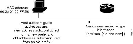
Simplified Network Renumbering for IPv6 Hosts
The strict aggregation of the global routing table requires that networks be renumbered when the service provider for the
network is changed. When the stateless autoconfiguration functionality in IPv6 is used to renumber a network, the prefix from
a new service provider is added to RA messages that are sent on the link. (The RA messages contain both the prefix from the
old service provider and the prefix from the new service provider.) Nodes on the link automatically configure additional addresses
by using the prefix from the new service provider. The nodes can then use the addresses created from the new prefix and the
existing addresses created from the old prefix on the link. Configuration of the lifetime parameters associated with the old
and new prefixes means that nodes on the link can make the transition to using only addresses created from the new prefix.
During a transition period, the old prefix is removed from RA messages and only addresses that contain the new prefix are
used on the link (the renumbering is complete) (see the figure below).
IPv6 General Prefixes
The upper 64 bits of an IPv6 address are composed from a global routing prefix plus a subnet ID, as defined in RFC 3513.
A general prefix (for example, /48) holds a short prefix, based on which a number of longer, more-specific prefixes (for example,
/64) can be defined. When the general prefix is changed, all of the more-specific prefixes based on it will change, too. This
function greatly simplifies network renumbering and allows for automated prefix definition.
For example, a general prefix might be 48 bits long (“/48”) and the more specific prefixes generated from it might be 64
bits long (“/64”). In the following example, the leftmost 48 bits of all the specific prefixes will be the same, and they
are the same as the general prefix itself. The next 16 bits are all different.
 General prefix: 2001:DB8:2222::/48
Specific prefix: 2001:DB8:2222:0000::/64
Specific prefix: 2001:DB8:2222:0001::/64
Specific prefix: 2001:DB8:2222:4321::/64
Specific prefix: 2001:DB8:2222:7744::/64
General prefixes can be defined in several ways:
-
Manually
-
Based on a 6to4 interface
-
Dynamically, from a prefix received by a Dynamic Host Configuration Protocol (DHCP) for IPv6 prefix delegation client
More specific prefixes, based on a general prefix, can be used when configuring IPv6 on an interface.
DHCP for IPv6 Prefix Delegation
DHCP for IPv6 can be used in environments to deliver stateful and stateless information. For further information about this
feature, see Implementing DHCP for IPv6.
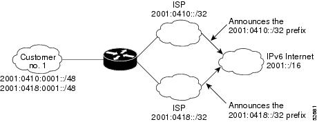
IPv6 Prefix Aggregation
The aggregatable nature of the IPv6 address space enables an IPv6 addressing hierarchy. For example, an enterprise can subdivide
a single IPv6 prefix from a service provider into multiple, longer prefixes for use within its internal network. Conversely,
a service provider can aggregate all of the prefixes of its customers into a single, shorter prefix that the service provider
can then advertise over the IPv6 internet (see the figure below).
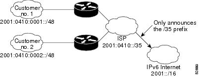
IPv6 Site Multihoming
Multiple IPv6 prefixes can be assigned to networks and hosts. Having multiple prefixes assigned to a network allows that
network to connect easily to multiple ISPs without breaking the global routing table (see the figure below).
IPv6 Data Links
In IPv6 networks, a data link is a network sharing a particular link-local prefix. Data links are networks arbitrarily segmented
by a network administrator in order to provide a multilevel, hierarchical routing structure while shielding the subnetwork
from the addressing complexity of attached networks. The function of a subnetwork in IPv6 is similar to a subnetwork in IPv4.
A subnetwork prefix is associated with one data link; multiple subnetwork prefixes may be assigned to the same data link.
The following data links are supported for IPv6: FDDI, Frame Relay PVC, Cisco High-Level Data Link Control (HDLC), PPP over
Packet over SONET, ISDN, and serial interfaces.
How to Implement IPv6 Addressing and Basic Connectivity
Configuring IPv6 Addressing and Enabling IPv6 Routing
Perform this task to assign IPv6 addresses to individual device interfaces and enable IPv6 traffic forwarding globally on
the device. By default, IPv6 addresses are not configured and IPv6 routing is disabled.
Note |
Multiple IPv6 link-local addresses on an interface are not supported. > |
SUMMARY STEPS
-
enable
-
configure
terminal
-
interface
type
number
- Do one of the following:
-
ipv6
address
ipv6-prefix
/prefix-length
eui-64 -
ipv6
address
ipv6-address
/
prefix-length
link-local
-
ipv6
enable
-
exit
-
ipv6
unicast-routing
DETAILED STEPS
| Command or Action | Purpose | |
|---|---|---|
| Step 1 |
Example: |
Enables privileged EXEC mode.
|
| Step 2 |
Example: |
Enters global configuration mode. |
| Step 3 |
Example: |
Specifies an interface type and number, and places the device in interface configuration mode. |
| Step 4 |
Do one of the following:
Example:Example:Example:Example:Example:Example: |
Specifies an IPv6 network assigned to the interface and enables IPv6 processing on the interface. or Specifies an IPv6 address assigned to the interface and enables IPv6 processing on the interface. or Automatically configures an IPv6 link-local address on the interface while also enabling the interface for IPv6 processing.
|
| Step 5 |
Example: |
Exits interface configuration mode, and returns the device to global configuration mode. |
| Step 6 |
Example: |
Enables the forwarding of IPv6 unicast datagrams. |
Configuring a Neighbor Discovery Cache Limit
Configuring a Neighbor Discovery Cache Limit on a Specified Interface
SUMMARY STEPS
-
enable
-
configure
terminal
-
interface
type
number
-
ipv6
nd
cache
interface-limit
size
[log
rate ]
DETAILED STEPS
| Command or Action | Purpose | |
|---|---|---|
| Step 1 |
Example: |
Enables privileged EXEC mode.
|
| Step 2 |
Example: |
Enters global configuration mode. |
| Step 3 |
Example: |
Specifies an interface type and number, and places the device in interface configuration mode. |
| Step 4 |
Example: |
Configures a Neighbor Discovery cache limit on a specified interface on the device.
|
Configuring a Neighbor Discovery Cache Limit on All Device Interfaces
SUMMARY STEPS
-
enable
-
configure
terminal
-
ipv6
nd
cache
interface-limit
size
[log
rate ]
DETAILED STEPS
| Command or Action | Purpose | |
|---|---|---|
| Step 1 |
Example: |
Enables privileged EXEC mode.
|
| Step 2 |
Example: |
Enters global configuration mode. |
| Step 3 |
Example: |
Configures a neighbor discovery cache limit on all interfaces on the device. |
Defining and Using IPv6 General Prefixes
General prefixes can be defined in several ways:
-
Manually
-
Based on a 6to4 interface
-
Dynamically, from a prefix received by a DHCP for IPv6 prefix delegation client
More specific prefixes, based on a general prefix, can be used when configuring IPv6 on an interface.
Defining a General Prefix Manually
SUMMARY STEPS
-
enable
-
configure
terminal
-
ipv6
general-prefix
prefix-name
{ipv6-prefix/prefix-length |
6to4
interface-type
interface-number}
DETAILED STEPS
| Command or Action | Purpose | |
|---|---|---|
| Step 1 |
Example: |
Enables privileged EXEC mode.
|
| Step 2 |
Example: |
Enters global configuration mode. |
| Step 3 |
Example: |
Defines a general prefix for an IPv6 address. |
Defining a General Prefix Based on a 6to4 Interface
SUMMARY STEPS
-
enable
-
configure
terminal
-
ipv6
general-prefix
prefix-name
{ipv6-prefix / prefix-length | 6to4 interface-type interface-number
DETAILED STEPS
| Command or Action | Purpose | |
|---|---|---|
| Step 1 |
Example: |
Enables privileged EXEC mode.
|
| Step 2 |
Example: |
Enters global configuration mode. |
| Step 3 |
Example: |
Defines a general prefix for an IPv6 address. When defining a general prefix based on a 6to4 interface, specify the 6to4 keyword and the interface-type interface-number arguments.
When defining a general prefix based on an interface used for 6to4 tunneling, the general prefix will be of the form 2001:a.b.c.d::/48, |
Defining a General Prefix with the DHCP for IPv6 Prefix Delegation Client Function
You can define a general prefix dynamically using the DHCP for IPv6 prefix delegation client function. For information on
how to perform this task, see the Implementing DHCP for IPv6 module.
Using a General Prefix in IPv6
SUMMARY STEPS
-
enable
-
configure
terminal
-
interface
type
number
-
ipv6
address
{ipv6-address / prefix-length | prefix-name sub-bits /prefix-length
DETAILED STEPS
| Command or Action | Purpose | |
|---|---|---|
| Step 1 |
Example: |
Enables privileged EXEC mode.
|
| Step 2 |
Example: |
Enters global configuration mode. |
| Step 3 |
Example: |
Specifies an interface type and number, and places the router in interface configuration mode. |
| Step 4 |
Example: |
Configures an IPv6 prefix name for an IPv6 address and enables IPv6 processing on the interface. |
Customizing IPv6 ICMP Rate Limiting
SUMMARY STEPS
-
enable
-
configure
terminal
-
ipv6
icmp
error-interval
milliseconds
[bucketsize ]
DETAILED STEPS
| Command or Action | Purpose | |
|---|---|---|
| Step 1 |
Example: |
Enables privileged EXEC mode.
|
| Step 2 |
Example: |
Enters global configuration mode. |
| Step 3 |
Example: |
Customizes the interval and bucket size for IPv6 ICMP error messages. |
Enabling Flow-Label Marking in Packets that Originate from the Device
This feature allows the device to track destinations to which the device has sent packets that are 1280 bytes or larger.
SUMMARY STEPS
-
enable
-
configure
terminal
-
ipv6
flowset
- exit
-
clear
ipv6
mtu
DETAILED STEPS
| Command or Action | Purpose | |
|---|---|---|
| Step 1 |
Example: |
Enables privileged EXEC mode.
|
| Step 2 |
Example: |
Enters global configuration mode. |
| Step 3 |
Example: |
Configures flow-label marking in 1280-byte or larger packets sent by the device. |
| Step 4 |
exit Example: |
Exits global configuration mode, and places the device in privileged EXEC mode. |
| Step 5 |
Example: |
Clears the MTU cache of messages. |
Clearing Messages from the IPv6 MTU Cache
SUMMARY STEPS
-
enable
-
clear
ipv6
mtu
DETAILED STEPS
| Command or Action | Purpose | |
|---|---|---|
| Step 1 |
Example: |
Enables privileged EXEC mode.
|
| Step 2 |
Example: |
Clears the MTU cache of messages. |
Configuring the DRP Extension for Traffic Engineering
Perform this task to configure the DRP extension to RAs in order to signal the preference value of a default router.
SUMMARY STEPS
-
enable
-
configure
terminal
-
interface
type
number
-
ipv6
nd
router-preference
{high | medium | low
DETAILED STEPS
| Command or Action | Purpose | |
|---|---|---|
| Step 1 |
Example: |
Enables privileged EXEC mode.
|
| Step 2 |
Example: |
Enters global configuration mode. |
| Step 3 |
Example: |
Specifies the interface type and number, and enters interface configuration mode. |
| Step 4 |
Example: |
Configures a DRP for a router on a specific interface |
Configuring Cisco Express Forwarding and Distributed Cisco Express Forwarding Switching for IPv6
Configuring Cisco Express
Forwarding
SUMMARY STEPS
-
enable -
configure
terminal
- Do
the following: -
ipv6cef
-
ipv6
cef
accounting
[non-recursive |per-prefix |
prefix-length ]
DETAILED STEPS
| Command or Action | Purpose | |||
|---|---|---|---|---|
| Step 1 |
Example: |
Enables
|
||
| Step 2 |
Example: |
Enters global |
||
| Step 3 |
Do
Example: |
Enables Cisco |
||
| Step 4 |
per-prefix | Example: |
Enables Cisco
|
Configuring Unicast RPF
Before you begin
To use uRPF, enable Cisco Express Forwarding switching or distributed Cisco Express Forwarding switching in the device. There
is no need to configure the input interface for Cisco Express Forwarding switching. As long as Cisco Express Forwarding is
running on the device, individual interfaces can be configured with other switching modes.
Note |
Cisco Express Forwarding must be configured globally in the device. uRPF will not work without Cisco Express Forwarding. |
Note |
uRPF should not be used on interfaces that are internal to the network. Internal interfaces are likely to have routing asymmetry, For example, devices at the edge of the network of an ISP are more likely to have symmetrical reverse paths than devices |
SUMMARY STEPS
-
enable
-
configure
terminal
-
interface
type
number
-
ipv6
verify
unicast
source
reachable-via
{rx |
any } [allow-default ] [allow-self-ping ] [access-list-name
DETAILED STEPS
| Command or Action | Purpose | |
|---|---|---|
| Step 1 |
Example: |
Enables privileged EXEC mode.
|
| Step 2 |
Example: |
Enters global configuration mode. |
| Step 3 |
Example: |
Specifies an interface type and number, and places the device in interface configuration mode. |
| Step 4 |
Example: |
Verifies that a source address exists in the FIB table and enables uRPF. |
Mapping Hostnames to IPv6 Addresses
Hostname-to-Address
Mappings
A name server is
used to track information associated with domain names. A name server can
maintain a database of hostname-to-address mappings. Each name can map to one
or more IPv4 addresses, IPv6 addresses, or both address types. In order to use
this service to map domain names to IPv6 addresses, you must specify a name
server and enable the DNS, which is the global naming scheme of the Internet
that uniquely identifies network devices.
Cisco software
maintains a cache of hostname-to-address mappings for use by the
connect ,
telnet , and
ping commands, related Telnet support operations, and many other commands that
generate command output. This cache speeds the conversion of names to
addresses.
Similar to IPv4,
IPv6 uses a naming scheme that allows a network device to be identified by its
location within a hierarchical name space that provides for domains. Domain
names are joined with periods (.) as the delimiting characters. For example,
Cisco is a commercial organization that is identified by a
com domain
name, so its domain name is
cisco.com . A
specific device in this domain, the FTP server, for example, is identified as
ftp.cisco.com .
SUMMARY STEPS
-
enable -
configure
terminal
- Do one of the
following: -
ip domain
name
[vrf
vrf-name ]
name -
ip domain
list
[vrf
vrf-name ]
name -
ip
name-server
[vrf
vrf-name ]
server-address1 [server-address2…server-address6 ] -
ip
domain-lookup
DETAILED STEPS
| Command or Action | Purpose | |||
|---|---|---|---|---|
| Step 1 |
Example: |
Enables
|
||
| Step 2 |
Example: |
Enters global |
||
| Step 3 |
Do one of the
Example:Example:Example: |
(Optional) or (Optional)
|
||
| Step 4 |
Example: |
Specifies one
|
||
| Step 5 |
Example: |
Enables
|
Mapping IPv6 Addresses to IPv6 Frame Relay Interfaces
Perform this task to map IPv6 addresses to Frame Relay PVCs. Specifically, the steps in this section explain how to explicitly
map IPv6 addresses to the Frame Relay PVCs used to reach the addresses.
Note |
This task shows how to configure Frame Relay PVCs. Several of the steps are labeled optional because many networks will require |
IPv6 for Cisco IOS XE Software Support for Wide-Area Networking Technologies
IPv6 for Cisco IOS XE software supports wide-area networking technologies such as Cisco HDLC, PPP over Packet over SONET (PoS),
ISDN, and serial (synchronous and asynchronous) interface types, and Frame Relay PVCs. These technologies function the same
in IPv6 as they do in IPv4—IPv6 does not enhance the technologies in any way.
IPv6 Addresses and PVCs
Broadcast and multicast are used in LANs to map protocol (network-layer) addresses to the hardware addresses of remote nodes
(hosts and routers). Because using broadcast and multicast to map network-layer addresses to hardware addresses in circuit-based
WANs such as Frame Relay networks is difficult to implement, these networks utilize implicit, explicit, and dynamic mappings
for the network-layer addresses of remote nodes and the PVCs used to reach the addresses.
Assigning an IPv6 address to an interface by using the ipv6 address command defines the IPv6 addresses for the interface and the network that is directly connected to the interface. If only
one PVC is terminated on the interface (the interface is a point-to-point interface), there is an implicit mapping between
all of the IPv6 addresses on the network and the PVC used to reach the addresses (no additional address mappings are needed).
If several PVCs are terminated on the interface (the interface is a point-to-multipoint interface), the frame-relay map ipv6
command is used to configure explicit mappings between the IPv6 addresses of the remote nodes and the PVCs used to reach the
addresses.
Note |
Given that IPv6 supports multiple address types, and depending on which applications or protocols are configured on a point-to-multipoint |
SUMMARY STEPS
-
enable
-
configure
terminal
-
interface
type
number
-
protocol
ipv6
ipv6-address
[[no ] broadcast ] -
frame-relay
map
ipv6
ipv6-address
dlci
[broadcast ] [cisco ] [ietf ]
[payload-compression packet-by-packet | frf9 stac
[hardware-options ] | data-stream stac
[hardware-options ]}] -
ipv6
address
ipv6-address
/
prefix-length
link-local
DETAILED STEPS
| Command or Action | Purpose | |
|---|---|---|
| Step 1 |
Example: |
Enables privileged EXEC mode.
|
| Step 2 |
Example: |
Enters global configuration mode. |
| Step 3 |
Example: |
Specifies an interface type and number, and places the router in interface configuration mode. |
| Step 4 |
Example: |
(Optional) Maps the IPv6 address of a remote node to the PVC used to reach the address. |
| Step 5 |
Example: |
(Optional) Maps the IPv6 address of a remote node to the data-link connection identifier (DLCI) of the PVC used to reach the |
| Step 6 |
Example: |
Specifies an IPv6 network assigned to the interface and enables IPv6 processing on the interface.
|
Displaying IPv6 Redirect
Messages
SUMMARY STEPS
-
enable -
show
ipv6
interface
[brief ] [type
number ] [prefix ] -
show
ipv6
route
[ipv6-address |
ipv6-prefix /prefix-length |
protocol |
interface-type
interface-number ] -
show
ipv6
traffic
-
show
hosts
[vrf
vrf-name |
all |
hostname |
summary ] -
enable
-
showrunning-config
DETAILED STEPS
| Command or Action | Purpose | |
|---|---|---|
| Step 1 |
Example: |
Enables
|
| Step 2 |
Example: |
Displays the |
| Step 3 |
Example: |
(Optional) |
| Step 4 |
Example: |
(Optional) |
| Step 5 |
Example: |
Displays the |
| Step 6 |
Example: |
Enables
|
| Step 7 |
running-config Example: |
Displays the |
Examples
Sample Output from the show ipv6 route Command
When the
ipv6-address or
ipv6-prefix/ prefix-length argument is specified, only route information for that address or network is displayed. The following is sample output from
the
show
ipv6
route command when entered with the IPv6 prefix 2001:DB8::/35:
Router# show ipv6 route 2001:DB8::/35
IPv6 Routing Table - 261 entries
Codes: C - Connected, L - Local, S - Static, R - RIP, B - BGP
I1 - ISIS L1, I2 - ISIS L2, IA - ISIS interarea
B 2001:DB8::/35 [20/3]
  via FE80::60:5C59:9E00:16, Tunnel1
Sample Output from the show ipv6 traffic Command
In the following example, the
show
ipv6
traffic command is used to display ICMP rate-limited counters:
Router# show ipv6 traffic
ICMP statistics:
  Rcvd: 188 input, 0 checksum errors, 0 too short
        0 unknown info type, 0 unknown error type
        unreach: 0 routing, 0 admin, 0 neighbor, 0 address, 0 port
        parameter: 0 error, 0 header, 0 option
        0 hopcount expired, 0 reassembly timeout,0 too big
        0 echo request, 0 echo reply
        0 group query, 0 group report, 0 group reduce
        1 router solicit, 175 router advert, 0 redirects
        0 neighbor solicit, 12 neighbor advert
  Sent: 7376 output, 56 rate-limited
        unreach: 0 routing, 15 admin, 0 neighbor, 0 address, 0 port
        parameter: 0 error, 0 header, 0 option
        0 hopcount expired, 0 reassembly timeout,0 too big
        15 echo request, 0 echo reply
        0 group query, 0 group report, 0 group reduce
        0 router solicit, 7326 router advert, 0 redirects
        2 neighbor solicit, 22 neighbor advert
Sample Output from the show frame-relay map Command
In the following example, the show frame-relay map command is used to verify that the IPv6 address of a remote node is mapped
to the DLCI of the PVC used to reach the address. The following example shows that the link-local and global IPv6 addresses
(FE80::E0:F727:E400:A and 2001:DB8:2222:1044::73; FE80::60:3E47:AC8:8 and 2001.DB8:2222:1044::72) of two remote nodes are
explicitly mapped to DLCI 17 and DLCI 19, respectively. Both DLCI 17 and DLCI 19 are terminated on interface serial 3 of this
node; therefore, interface serial 3 of this node is a point-to-multipoint interface.
Router# show frame-relay map
Serial3 (up): ipv6 FE80::E0:F727:E400:A dlci 17(0x11,0x410), static,
              broadcast, CISCO, status defined, active
Serial3 (up): ipv6 2001:DB8:2222:1044::72 dlci 19(0x13,0x430), static,
              CISCO, status defined, active
Serial3 (up): ipv6 2001:DB8:2222:1044::73 dlci 17(0x11,0x410), static,
              CISCO, status defined, active
Serial3 (up): ipv6 FE80::60:3E47:AC8:8 dlci 19(0x13,0x430), static,
              broadcast, CISCO, status defined, active
Sample Output from the show hosts Command
The state of the name lookup system on the DHCP for IPv6 client can be displayed with the
show
hosts command:
Router# show hosts
Default domain is not set
Domain list:verybigcompany.com
Name/address lookup uses domain service
Name servers are 2001:DB8:A:B::1, 2001:DB8:3000:3000::42
Codes:UN - unknown, EX - expired, OK - OK, ?? - revalidate
       temp - temporary, perm - permanent
       NA - Not Applicable None - Not defined
Host                      Port  Flags      Age Type   Address(es)
sdfasfd                   None  (temp, UN)  0  IPv6
Sample Output from the show running-config Command
In the following example, the
show
running-config command is used to verify that IPv6 processing of packets is enabled globally on the router and on applicable interfaces,
and that an IPv6 address is configured on applicable interfaces:
Router# show running-config
Building configuration...
Current configuration : 22324 bytes
!
! Last configuration change at 14:59:38 PST Tue Jan 16 2001
! NVRAM config last updated at 04:25:39 PST Tue Jan 16 2001 by bird
!
hostname Router
!
ipv6 unicast-routing
!
interface gigabitethernet0/0/0
 no ip route-cache
 no ip mroute-cache
 no keepalive
 media-type 10BaseT
        ipv6 address 2001:DB8:0:1::/64 eui-64
In the following example, the
show
running-config command is used to verify that Cisco Express Forwarding and network accounting for Cisco Express Forwarding have been enabled
globally on a nondistributed architecture platform, and that Cisco Express Forwarding has been enabled on an IPv6 interface.
The following output shows that both that Cisco Express Forwarding and network accounting for Cisco Express Forwarding have
been enabled globally on the router, and that Cisco Express Forwarding has also been enabled on Gigabit Ethernet interface
0/0/0:
Router# show running-config
Building configuration...
Current configuration : 22324 bytes
!
! Last configuration change at 14:59:38 PST Tue Jan 16 2001
! NVRAM config last updated at 04:25:39 PST Tue Jan 16 2001 by bird
!
hostname Router
!
ip cef
ipv6 unicast-routing
ipv6 cef
ipv6 cef accounting prefix-length
!
!
interface gigabitethernet0/0/0
 ip address 10.4.9.11 255.0.0.0
 media-type 10BaseT
 ipv6 address 2001:DB8:C18:1::/64 eui-64
!
In the following example, the
show
running-config command is used to verify static hostname-to-address mappings, default domain names, and name servers in the hostname cache,
and to verify that the DNS service is enabled:
Router# show running-config
Building configuration...
!
ipv6 host cisco-sj 2001:DB8:20:1::12
!
ip domain-name cisco.com
ip domain-lookup
ip name-server 2001:DB8:C01F:768::1
Configuration Examples for Implementing IPv6 Addressing and Basic Connectivity
Example: IPv6 Addressing and IPv6 Routing Configuration
In the following example, IPv6 is enabled on the device with both a link-local address and a global address based on the
IPv6 prefix 2001:DB8:c18:1::/64. The EUI-64 interface ID is used in the low-order 64 bits of both addresses. Output from the
show
ipv6
interface command is included to show how the interface ID (260:3EFF:FE47:1530) is appended to the link-local prefix FE80::/64 of Gigabit
Ethernet interface 0/0/0.
ipv6 unicast-routing
interface gigabitethernet 0/0/0
  ipv6 address 2001:DB8:c18:1::/64 eui-64
Device# show ipv6 interface gigabitethernet 0/0/0
Gigabitethernet0/0/0 is up, line protocol is up
 IPv6 is enabled, link-local address is FE80::260:3EFF:FE47:1530
  Global unicast address(es):
    2001:DB8:C18:1:260:3EFF:FE47:1530, subnet is 2001:DB8:C18:1::/64
  Joined group address(es):
    FF02::1
    FF02::2
    FF02::1:FF47:1530
    FF02::9
  MTU is 1500 bytes
  ICMP error messages limited to one every 500 milliseconds
  ND reachable time is 30000 milliseconds
  ND advertised reachable time is 0 milliseconds
  ND advertised retransmit interval is 0 milliseconds
  ND router advertisements are sent every 200 seconds
  ND router advertisements live for 1800 seconds
  Hosts use stateless autoconfig for addresses.
Example: Dual-Protocol Stacks Configuration
The following example enables the forwarding of IPv6 unicast datagrams globally on the device and configures Gigabit Ethernet
interface 0/0/0 with both an IPv4 address and an IPv6 address:
ipv6 unicast-routing
interface gigabitethernet0/0/0
  ip address 192.168.99.1 255.255.255.0
 ipv6 address 2001:DB8:c18:1::3/64
Example: IPv6 ICMP Rate Limiting Configuration
The following example shows an interval of 50 milliseconds and a bucket size of 20 tokens being configured for IPv6 ICMP
error messages:
ipv6 icmp error-interval 50 20Example: Cisco Express
Forwarding
Configuration
In the following
example, both Cisco Express Forwarding for IPv6 and network accounting for
Cisco Express Forwarding for IPv6 have been enabled globally on a
nondistributed architecture device, and Cisco Express Forwarding for IPv6 has
been enabled on Gigabit Ethernet interface 0/0/0. The example also shows that
the forwarding of IPv6 unicast datagrams has been configured globally on the
device with the
ipv6
unicast-routing command, an IPv6 address has been
configured on Gigabit Ethernet interface 0/0/0 with the
ipv6
address command, and Cisco Express Forwarding for
IPv4 has been configured globally on the device with the
ip
cef command.
ip cef
ipv6 unicast-routing
ipv6 cef
ipv6 cef accounting prefix-length
interface gigabitethernet0/0/0
 ip address 10.4.9.11 255.0.0.0
 media-type 10BaseT
 ipv6 address 2001:DB8:C18:1::/64 eui-64
Example: Hostname-to-Address
Mappings Configuration
The following
example defines two static hostname-to-address mappings in the hostname cache,
establishes a domain list with several alternate domain names to complete
unqualified hostnames, specifies host 2001:DB8::250:8bff:fee8:f800 and host
2001:DB8:0:f004::1 as the name servers, and reenables the DNS service:
ip domain list domain1-list.com
ip domain list serviceprovider2-name.com
ip domain list college2-name.edu
ip name-server 2001:DB8::250:8bff:fee8:f800 2001:DB8:0:f004::1
ip domain-lookup
Example IPv6 Address to Frame Relay PVC Mapping Configuration
Example IPv6 Frame Relay PVC Mapping Configuration (Point-to-Point Interface)
In the following example, three nodes named Router A, Router B, and Router C make up a fully meshed network. Each node is
configured with two PVCs, which provide an individual connection to each of the other two nodes. Each PVC is configured on
a different point-to-point subinterface, which creates three unique IPv6 networks (2001:DB8:2222:1017:/64, 2001:DB8:2222:1018::/64,
and 2001:DB8:2222:1019::/64). Therefore, the mappings between the IPv6 addresses of each node and the DLCI (DLCI 17, 18, and
19) of the PVC used to reach the addresses are implicit (no additional mappings are required).
Note |
Given that each PVC in the following example is configured on a different point-to-point subinterface, the configuration in |
Router A Configuration
interface Serial 3
 encapsulation frame-relay
!
interface Serial3.17 point-to-point
 description to Router B
 ipv6 address 2001:DB8:2222:1017::46/64
 frame-relay interface-dlci 17
!
interface Serial 3.19 point-to-point
 description to Router C
 ipv6 address 2001:DB8:2222:1019::46/64
 frame-relay interface-dlci 19
Router B Configuration
interface Serial 5
 encapsulation frame-relay
!
interface Serial5.17 point-to-point
 description to Router A
 ipv6 address 2001:DB8:2222:1017::73/64
 frame-relay interface-dlci 17
!
interface Serial5.18 point-to-point
 description to Router C
 ipv6 address 2001:DB8:2222:1018::73/64
 frame-relay interface-dlci 18
Router C Configuration
interface Serial 0
 encapsulation frame-relay
!
interface Serial0.18 point-to-point
 description to Router B
 ipv6 address 2001:DB8:2222:1018::72/64
 frame-relay interface-dlci 18
!
interface Serial0.19 point-to-point
 description to Router A
 ipv6 address 2001:DB8:2222:1019::72/64
 frame-relay interface-dlci 19
Example IPv6 Frame Relay PVC Mapping Configuration (Point-to-Multipoint Interface)
In the following example, the same three nodes (Router A, Router B, and Router C) from the previous example make up a fully
meshed network and each node is configured with two PVCs (which provide an individual connection to each of the other two
nodes). However, the two PVCs on each node in the following example are configured on a single interface (serial 3, serial
5, and serial 10, respectively), which makes each interface a point-to-multipoint interface. Therefore, explicit mappings
are required between the link-local and global IPv6 addresses of each interface on all three nodes and the DLCI (DLCI 17,
18, and 19) of the PVC used to reach the addresses.
Router A Configuration
interface Serial 3
 encapsulation frame-relay
 ipv6 address 2001:DB8:2222:1044::46/64
 frame-relay map ipv6 FE80::E0:F727:E400:A 17 broadcast
 frame-relay map ipv6 FE80::60:3E47:AC8:8 19 broadcast
 frame-relay map ipv6 2001:DB8:2222:1044::72 19
 frame-relay map ipv6 2001:DB8:2222:1044::73 17
Router B Configuration
interface Serial 5
 encapsulation frame-relay
 ipv6 address 2001:DB8:2222:1044::73/64
 frame-relay map ipv6 FE80::60:3E59:DA78:C 17 broadcast
 frame-relay map ipv6 FE80::60:3E47:AC8:8 18 broadcast
 frame-relay map ipv6 2001:DB8:2222:1044::46 17
 frame-relay map ipv6 2001:DB8:2222:1044::72 18
Router C Configuration
interface Serial 10
 encapsulation frame-relay
 ipv6 address 2001:DB8:2222:1044::72/64
 frame-relay map ipv6 FE80::60:3E59:DA78:C 19 broadcast
 frame-relay map ipv6 FE80::E0:F727:E400:A 18 broadcast
 frame-relay map ipv6 2001:DB8:2222:1044::46 19
 frame-relay map ipv6 2001:DB8:2222:1044::73 18
Additional References
Related Documents
|
Related Topic |
Document Title |
|---|---|
|
IPv6 supported feature list |
Start Here: Cisco IOS XE Software Release Specifics for IPv6 Features |
|
IPv6 commands: complete command syntax, command mode, defaults, usage guidelines, and examples |
Cisco IOS IPv6 Command Reference |
|
IPv6 DHCP description and configuration |
Implementing DHCP for IPv6 |
|
IPv4 addressing configuration tasks |
Configuring IPv4 Addresses |
|
IPv4 services configuration tasks |
Configuring IP Services |
|
IPv4 addressing commands |
Cisco IOS IP Addressing Services Command Reference |
|
IPv4 IP services commands |
Cisco IOS IP Application Services Command Reference |
|
Stateful Switchover |
Configuring Stateful Switchover |
|
In Service Software Upgrade |
Cisco IOS XE In Service Software Upgrade Process |
|
Switching commands |
Cisco IOS IP Switching Command Reference |
|
Cisco IOS master command list, all releases |
Cisco IOS Master Command List, All Releases |
Standards
|
Standards |
Title |
|---|---|
|
No new or modified standards are supported by this feature, and support for existing standards has not been modified by this |
— |
MIBs
|
MIBs |
MIBs Link |
|---|---|
|
None |
To locate and download MIBs for selected platforms, Cisco software releases, and feature sets, use Cisco MIB Locator found http://www.cisco.com/go/mibs |
RFCs
|
RFCs |
Title |
|---|---|
|
RFC 1981 |
Path MTU Discovery for IP version 6 |
|
RFC 2373 |
IP Version 6 Addressing Architecture |
|
RFC 2374 |
An Aggregatable Global Unicast Address Format |
|
RFC 2460 |
Internet Protocol, Version 6 (IPv6) Specification |
|
RFC 2461 |
Neighbor Discovery for IP Version 6 (IPv6) |
|
RFC 2462 |
IPv6 Stateless Address Autoconfiguration |
|
RFC 2463 |
Internet Control Message Protocol (ICMPv6) for the Internet Protocol Version 6 (IPv6) Specification |
|
RFC 2467 |
Transmission of IPv6 Packets over FDDI Networks |
|
RFC 2472 |
IP Version 6 over PPP |
|
RFC 2590 |
Transmission of IPv6 Packets over Frame Relay Networks Specification |
|
RFC 3152 |
Delegation of IP6.ARPA |
|
RFC 3162 |
RADIUS and IPv6 |
|
RFC 3513 |
Internet Protocol Version 6 (IPv6) Addressing Architecture |
|
RFC 3596 |
DNS Extensions to Support IP version 6 |
Technical Assistance
|
Description |
Link |
|---|---|
|
The Cisco Support and Documentation website provides online resources to download documentation, software, and tools. Use |
http://www.cisco.com/cisco/web/support/index.html |
Feature Information for Implementing IPv6 Addressing and Basic Connectivity
The following table provides release information about the feature or features described in this module. This table lists
only the software release that introduced support for a given feature in a given software release train. Unless noted otherwise,
subsequent releases of that software release train also support that feature.
Use Cisco Feature Navigator to find information about platform support and Cisco software image support. To access Cisco
Feature Navigator, go to www.cisco.com/go/cfn. An account on Cisco.com is not required.
|
Feature Name |
Releases |
Feature Information |
|---|---|---|
|
IPv6—Base Protocols High Availability |
Cisco IOS XE Release 2.1 |
IPv6 Neighbor Discovery supports SSO. |
|
IPv6—ICMPv6 |
Cisco IOS XE Release 2.1 |
ICMP for IPv6 generates error messages, such as ICMP destination unreachable messages, and informational messages, such as |
|
IPv6—ICMPv6 Redirect |
Cisco IOS XE Release 2.1 |
A value of 137 in the Type field of the ICMP packet header identifies an IPv6 neighbor redirect message. Routers send neighbor |
|
IPv6—ICMP Rate Limiting |
Cisco IOS XE Release 2.1 |
The IPv6 ICMP rate limiting feature implements a token bucket algorithm for limiting the rate at which IPv6 ICMP error messages |
|
IPv6—IPv6 Default Router Preferences |
Cisco IOS XE Release 2.1 |
The DRP extension provides a coarse preference metric (low, medium, or high) for default routers. |
|
IPv6—IPv6 MTU Path Discovery |
Cisco IOS XE Release 2.1 |
Path MTU discovery in IPv6 allows a host to dynamically discover and adjust to differences in the MTU size of every link |
|
IPv6—IPv6 Neighbor Discovery |
Cisco IOS XE Release 2.1 |
The IPv6 Neighbor Discovery process uses ICMP messages and solicited-node multicast addresses to determine the link-layer |
|
IPv6—IPv6 Neighbor Discovery Duplicate Address Detection |
Cisco IOS XE Release 2.1 |
IPv6 Neighbor Discovery duplicate address detection is performed first on a new, link-local IPv6 address before the address |
|
IPv6—IPv6 Stateless Autoconfiguration |
Cisco IOS XE Release 2.1 |
The IPv6 stateless autoconfiguration feature can be used to manage link, subnet, and site addressing changes. |
|
IPv6—Per-Interface Neighbor Discovery Cache Limit |
Cisco IOS XE Release 2.6 |
The per-interface Neighbor Discovery cache limit feature provides the ability to limit the number of Neighbor Discovery cache The following commands were introduced or modified for this feature:
|
|
IPv6—IPv6 Static Cache Entry for Neighbor Discovery |
Cisco IOS XE Release 2.1 |
The IPv6 static cache entry for Neighbor Discovery feature allows static entries to be made in the IPv6 neighbor cache. |
|
IPv6 Data Link—Cisco High-Level Data Link Control (HDLC) |
Cisco IOS XE Release 2.1 |
In IPv6 networks, a data link is a network sharing a particular link-local prefix. HDLC is a type of data link supported |
|
IPv6 Data Link—Fast Ethernet |
Cisco IOS XE Release 2.1 |
In IPv6 networks, a data link is a network sharing a particular link-local prefix. Fast Ethernet data links supported for |
|
IPv6 Data Link—FDDI |
Cisco IOS XE Release 2.1 |
In IPv6 networks, a data link is a network sharing a particular link-local prefix. FDDI is a type of data link supported |
|
IPv6 Data Link—Frame Relay PVC |
Cisco IOS XE Release 2.1 |
In IPv6 networks, a data link is a network sharing a particular link-local prefix. Frame relay PVC is a type of data link |
|
IPv6 Data Link—PPP Service over Packet over SONET, ISDN, and Serial (Synchronous and Asynchronous) Interfaces |
Cisco IOS XE Release 2.1 |
In IPv6 networks, a data link is a network sharing a particular link-local prefix. PPP service over Packet over SONET, ISDN, |
|
IPv6 Data Link—VLANs Using IEEE 802.1Q Encapsulation |
Cisco IOS XE Release 2.1 |
In IPv6 networks, a data link is a network sharing a particular link-local prefix. VLANs using IEEE 802.1Q encapsulation |
|
IPv6 Services—AAAA DNS Lookups over an IPv4 Transport |
Cisco IOS XE Release 2.1 |
IPv6 basic connectivity can be enhanced by configuring support for AAAA record types in the DNS name-to-address and address-to-name |
|
IPv6 Services—Cisco Discovery Protocol—IPv6 Address Family Support for Neighbor Information |
Cisco IOS XE Release 2.1 |
The Cisco Discovery Protocol IPv6 address support for neighbor information feature adds the ability to transfer IPv6 addressing |
|
IPv6 Services—DNS Lookups over an IPv6 Transport |
Cisco IOS XE Release 2.1 |
IPv6 supports DNS record types that are supported in the DNS name-to-address and address-to-name lookup processes. |
|
IPv6 Switching—Cisco Express Forwarding and Distributed Cisco Express Forwarding Support |
Cisco IOS XE Release 2.1 |
Cisco Express Forwarding for IPv6 is advanced, Layer 3 IP switching technology for the forwarding of IPv6 packets. Distributed |
|
SSO/ISSU Support for per-User IPv6 ACL for PPP Sessions |
Cisco IOS XE 3.2.1S |
Reproducing IPv6 ACLs on the active RP to the standby RP provides a consistent SSO and ISSU experience for active sessions. |
|
Unicast Reverse Path Forwarding for IPv6 |
Cisco IOS XE Release 2.1 |
The Unicast RPF feature mitigates problems caused by malformed or forged (spoofed) IPv6 source addresses that pass through |
An IPv6 is the sixth version of any IP address on the IP protocol. It consists of eight groups of four hexadecimal digits. IP v6 is a 128-bits address having an address space of 2^128.
For more details about IPv6 refer to the articles: What is IPv6? and Internet Protocol version 6 (IPv6).
Steps to Configure IPv6 on Cisco Packets Tracer:
Step 1: First open the Cisco packet tracer desktop and create a network topology something like the image and an IPv6 addressing table given below.
| S.NO | Device Name | Model-Name | Link-Local-Address | Default-Gateway |
|---|---|---|---|---|
| 1. | PC | PC | FE80::207:ECFF:FEA3:EB56 | FE80::1 |
| 2. | Switch | PT-switch | FE80::207:ECFF:FEB9:862A | FE80::1 |
| 3. | Router | 2911 | FE80::250:FFF:FE6C:B21 | FE80::1 |
| 4. | cable | Automatic connecting cable | nil | nil |
IP Addressing Table:
| S.NO | Interface | IPv6 Address |
|---|---|---|
| 1. | Gig0/0 | 2001:DB:AAAA:A::1/64 |
| 2. | Gig0/1 | 2001:DB:AAAA:B::1/64 |
Step 2: Configuring the GigabitEthernet Interfaces.
- First, we will configure the GigabitEthernet0/0 using CLI.
- Click on router0 and go to CLI and type the commands are given below:
Router>en
Router#conf t
Enter configuration commands, one per line.  End with CNTL/Z.
Router(config)#ipv6 unicast-routing
Router(config)#int Gig0/0
Router(config-if)#ipv6 address FE80::1 link
Router(config-if)#ipv6 address FE80::1 link-local
Router(config-if)#no shut
- Now we will configure the GigabitEthernet0/1 Interface.
- Click on router0 and go to CLI and type the commands are given below:
Router(config-if)#int Gig0/1
Router(config-if)#ipv6 address FE80::1 link-local
Router(config-if)#no shut
- Then, both the interfaces will be active now:
Step 3: Configuring Ipv6 address in both Interfaces using CLI:
- CLI commands to configure IPv6 address in GigabitEthernet0/0 and GigabitEthernet0/1 ports are given below:
Router#en
Router#conf t
Enter configuration commands, one per line.  End with CNTL/Z.
Router(config)#int Gig0/0
Router(config-if)#ipv6 address 2001:DB8:AAAA:A::1/64
Router(config-if)#no shut
Router(config-if)#int Gig0/1
Router(config-if)#ipv6 address 2001:DB8:AAAA:B::1/64
Router(config-if)#no shut
Router(config-if)#
Router(config-if)#
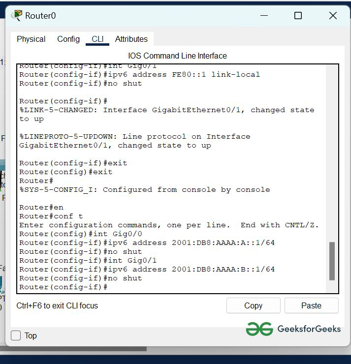
Step 4: We have configured the router now change the settings of hosts in IPv6 configuration:
- First, click on PC0 and go to desktop then IP configuration.
- Now find the IPv6 configuration.
- Change the settings from static to automatic and then after a few seconds, the IPv6 address and default gateway are displayed.
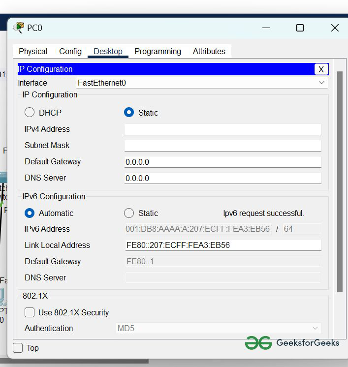
- Similarly, repeat this procedure with PC1 and PC2
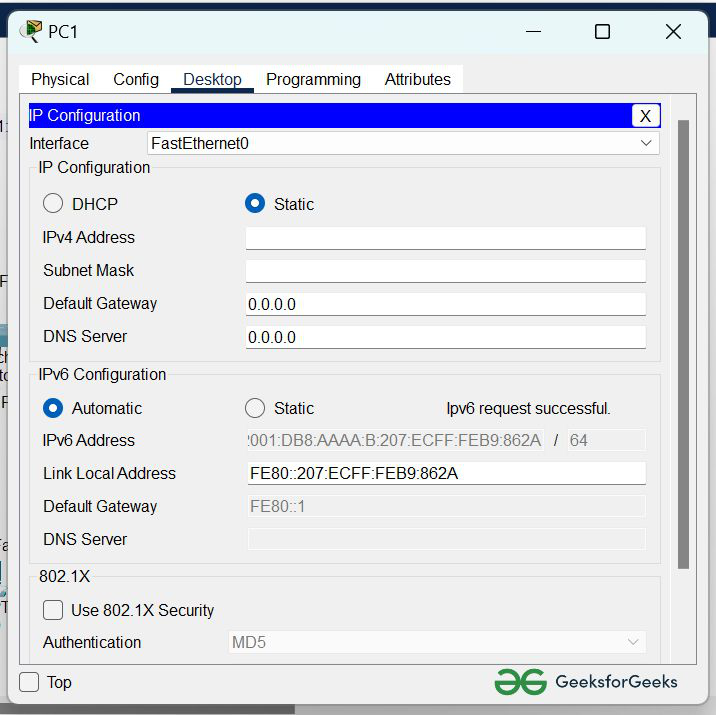
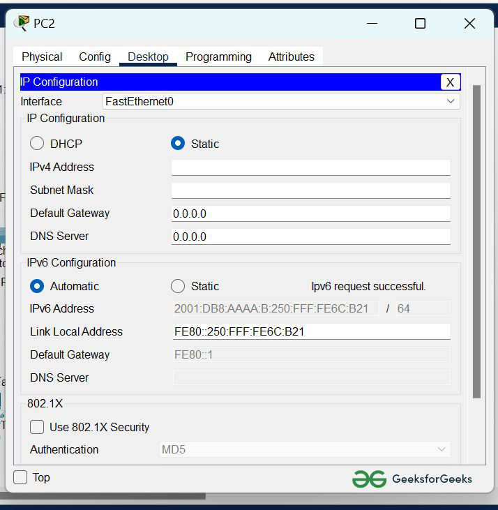
Step 5: Now we have to verify the connection by pinging the IPv6 address of PC0 in PC1.
- First, click on PC1 and go to the command prompt, and type ping <ipv6 address>
command: ping 2001:DB8:AAAA:A:20D:BDFF:FE1A:D121
- As we can see in the below image, getting replies from PC0 means the connection is established successfully.
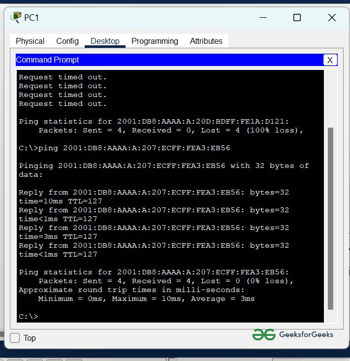
Simulation Result:
Last Updated :
22 Jun, 2022
Like Article
Save Article
Время на прочтение
7 мин
Количество просмотров 53K

Введение
Протокол IPv6 является наследником повсеместно используемого сегодня протокола IP четвёртой версии, IPv4, и естественно, наследует большую часть логики работы этого протокола. Так, например, заголовки пакетов в IPv4 и IPv6 очень похожи, используется та же логика пересылки пакетов – маршрутизация на основе адреса получателя, контроль времени нахождения пакета в сети с помощью TTL и так далее. Однако, есть и существенные отличия: кроме изменения длины самого IP-адреса произошёл отказ от использования широковещания в любой форме, включая направленное (Broadcast, Directed broadcast). Вместо него теперь используются групповые рассылки (multicast). Также исчез ARP-протокол, функции которого возложены на ICMP, что заставит отделы информационной безопасности внимательнее относиться к данному протоколу, так как простое его запрещение уже стало невозможным. Мы не станем описывать все изменения, произошедшие с протоколом, так как читатель сможет с лёгкостью найти их на большинстве IT-ресурсов. Вместо этого покажем практические примеры настройки устройств на базе Cisco IOS для работы с IPv6.
Многие начинающие сетевые специалисты задаются вопросом: «Нужно ли сейчас начинать изучать IPv6?» На наш взгляд, сегодня уже нельзя подходить к IPv6 как к отдельной главе или технологии, вместо этого все изучаемые техники и методики следует отрабатывать сразу на обоих версиях протокола IP. Так, например, при изучении работы протокола динамической маршрутизации EIGRP стоит проводить настройку тестовых сетей в лаборатории как для IPv4, так и для IPv6 одновременно. Перейдём от слов к делу!
Адресация в IPv6
Длина адреса протокола IPv6 составляет 128 бит, что в четыре раза больше той, которая была в IPv4. Количество адресов IPv6 огромно и составляет 2128≈3,4⋅1038. Сам адрес протокола IPv6 можно разделить на две части: префикс и адрес хоста, которую ещё называют идентификатором интерфейса. Такое деление очень похоже на то, что использовалось в IPv4 при бесклассовой маршрутизации.
Адреса в IPv6 записываются в шестнадцатеричной форме, каждая группа из четырёх цифр отделяется двоеточием. Например, 2001:1111:2222:3333:4444:5555:6666:7777.
Маска указывается через слеш, то есть, например, /64.
В адресе протокола IPv6 могут встречаться длинные последовательности нулей, поэтому предусмотрена сокращённая запись адреса. Во-первых, могут не записываться начальные нули каждой группы цифр, то есть вместо адреса 2001:0001:0002:0003:0004:0005:0006:7000 можно записать 2001:1:2:3:4:5:6:7000. Конечные нули при этом не удаляются. В случае, когда группа цифр в адресе (или несколько групп подряд) содержит только нули, она может быть заменена на двойное двоеточие. Например, вместо адреса 2001:1:0:0:0:0:0:1 может использоваться сокращённая запись вида 2001:1::1. Стоит отметить, что сократить адрес таким образом можно только один раз.
Ниже приводятся правильные и неправильные формы записи IPv6 адресов.
Правильная запись.
2001:0000:0db8:0000:0000:0000:07a0:765d
2001:0:db8:0:0:0:7a0:765d
2001:0:db8::7a0:765d
Ошибочная форма.
2001::db8::7a0:765d
2001:0:db8::7a:765d
Забавные сокращения.
::/0 – шлюз по умолчанию
::1 – loopback
2001:2345:6789::/64 – адрес какой-то сети
Однако не все адреса протокола IPv6 могут быть назначены узлам в глобальной сети. Существует несколько зарезервированных диапазонов и типов адресов. Адрес IPv6 может относиться к одному из трёх следующих типов.
• Unicast
• Multicast
• Anycast
Адреса Unicast очень похожи на аналогичные адреса протокола IPv4, они могут назначаться интерфейсам сетевых устройств, серверам и хостам конечных пользователей. Групповые или Multicast адреса предназначены для доставки пакетов сразу нескольким получателям, входящим в группу. При использовании Anycast адресов данные будут получены ближайшим узлом, которому назначен такой адрес. Стоит обратить особое внимание на то, что в списке поддерживаемых протоколом IPv6 адресов отсутствуют широковещательные адреса. Даже среди Unicast адресов существует более мелкое дробление на типы.
• Link local
• Global unicast
• Unique local
Адреса, относящиеся к группе Unique local, описаны в RFC 4193 и по своему назначению очень похожи на приватные адреса протокола IPv4, описанные в RFC 1918. Адреса группы Link local предназначены для передачи информации между устройствами, подключёнными к одной L2-сети. Большинство адресов из диапазона Global unicast могут быть назначены интерфейсам конкретных сетевых узлов. Список зарезервированных адресов представлен ниже.
| Адрес | Маска | Описание | Заметки |
| :: | 128 | — | Аналог 0.0.0.0 в IPv4 |
| ::1 | 128 | Loopback | Аналог 127.0.0.1 в IPv4 |
| ::xx.xx.xx.xx | 96 | Встроенный IPv4 | IPv4 совместимый. Устарел, не используется |
| ::ffff:xx.xx.xx.xx | 96 | IPv4, отображённый на IPv6 | Для хостов, не поддерживающих IPv6 |
| 2001:db8:: | 32 | Документирование | Зарезервирован для примеров. RFC 3849 |
| fe80:: — febf:: | 10 | Link-local | Аналог 169.254.0.0/16 в IPv4 |
| fc00:: | 7 | Unique Local Unicast | Пришёл на смену Site-Local. RFC 4193 |
| ffxx:: | 8 | Multicast | — |
Базовая настройка интерфейсов
Включение маршрутизации IPv6 производится с помощью команды ipv6 unicast-routing. В принципе, поддержка маршрутизатором протокола IPv6 будет производиться и без введения указанной команды, однако без неё устройство будет выполнять функции хоста для IPv6. Многие команды, к которым вы привыкли в IPv4, присутствуют также и в IPv6, однако для них вместо опции ip нужно будет указывать слово ipv6.
Настройка адреса на интерфейсе возможна несколькими способами. При одном лишь включении поддержки IPv6 на интерфейсе автоматически назначается link-local адрес.
R1#conf t
Enter configuration commands, one per line.  End with CNTL/Z.
R1(config)#int gi0/0
R1(config-if)#ipv6 enable
R1(config-if)#^Z
R1#show ipv6 int bri
Ethernet0/0                [administratively down/down]
    unassigned
GigabitEthernet0/0         [up/up]
    FE80::C800:3FFF:FED0:A008
Вычисление части адреса link-local производится с помощью алгоритма EUI-64 на основе MAC-адреса интерфейса. Для этого в середину 48 байтного МАС-адреса автоматически дописывается два байта, которые в шестнадцатеричной записи имеют вид FFFE, а также производится инвертирование седьмого бита первого байта MAC-адреса. На рисунках ниже схематично показана работа обсуждаемого алгоритма.

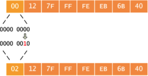
Сравните указанные выше link-local адрес с физическим адресом интерфейса Gi0/0 маршрутизатора (несущественная часть вывода команды sho int Gi0/0 удалена).
R1#show int gi0/0
GigabitEthernet0/0 is up, line protocol is up
  Hardware is i82543 (Livengood), address is ca00.3fd0.a008 (bia ca00.3fd0.a008)
EUI-64 часть IPv6 адреса: CA00:3FFF:FED0:A008.
Назначение адреса на интерфейс вручную производится с помощью команды ipv6 address, например, ipv6 address 2001:db8::1/64. Возможно лишь указывать адрес сегмента сети, оставшаяся часть будет назначаться автоматически с использованием преобразованного с помощью EUI-64 физического адреса интерфейса, для чего используйте команду с ключевым словом eui-64.
R2#conf t
R2(config)#int gi0/0
R2(config-if)#ipv ad 2001:db8::/64 eui-64
R2(config-if)#^Z
R2#show ipv6 int bri
Ethernet0/0                [administratively down/down]
    unassigned
GigabitEthernet0/0         [up/up]
    FE80::C801:42FF:FEA4:8
    2001:DB8::C801:42FF:FEA4:8
Обмен сообщениями внутри одного L2-сегмента только с помощью адресов link-local возможен и в некоторых случаях используется, однако в большинстве ситуаций интерфейсу должен быть назначен обычный маршрутизируемый IPv6-адрес. Так, например, соседство по протоколам OSPF или EIGRP устанавливается с использованием link-local адресов. Автоматический поиск соседа и другие служебные протоколы также работают по link-local адресам
R1#sho ipv6 int brief
Ethernet0/0                [administratively down/down]
    unassigned
GigabitEthernet0/0         [up/up]
    FE80::C800:42FF:FEA4:8
    2001:DB8::1
R1#sho ipv ei ne
IPv6-EIGRP neighbors for process 1
H   Address                 Interface       Hold Uptime   SRTT   RTO  Q  Seq
                                            (sec)         (ms)       Cnt Num
0   Link-local address:     Gi0/0             12 00:01:03   39   234  0  3
    FE80::C801:42FF:FEA4:8

R1#ping FE80::C801:42FF:FEA4:8

Output Interface: GigabitEthernet0/0
Type escape sequence to abort.
Sending 5, 100-byte ICMP Echos to FE80::C801:42FF:FEA4:8, timeout is 2 seconds:
Packet sent with a source address of FE80::C800:42FF:FEA4:8
!!!!!
Success rate is 100 percent (5/5), round-trip min/avg/max = 4/20/48 ms
Естественно, сохранилась и возможность автоматического назначения адреса в IPv6 с помощью протокола DHCP. Стоит, правда, отметить, что в IPv6 существует два различных типа DHCP: stateless и stateful, настройка которых производится с помощью команд ipv6 address autoconfig и ipv6 address dhcp соответственно.
Как уже было отмечено ранее, в IPv6 протокол ARP более не используется. Определение соседей производится с помощью протокола NDP (Neighbor Discovery Protocol) путём обмена сообщениями ICMP, отправляя их на групповой адрес FF02::1.
R1#show ipv6 neighbors
IPv6 Address                              Age Link-layer Addr State Interface
FE80::C801:42FF:FEA4:8                     25 ca01.42a4.0008  STALE Gi0/0
В операционных системах семейства Windows также присутствует возможность просмотра списка соседей (аналог команды arp –a), правда, теперь придётся использовать более длинный системный вызов.
C:\>netsh interface ipv6 show neighbors
Interface 1: Loopback Pseudo-Interface 1
Internet Address                              Physical Address   Type
--------------------------------------------  -----------------  -----------
ff02::c                                                          Permanent
ff02::16                                                         Permanent
ff02::1:2                                                        Permanent
ff02::1:3                                                        Permanent
ff02::1:ff1e:f939                                                Permanent
Interface 24: Подключение по локальной сети 4
Internet Address                              Physical Address   Type
--------------------------------------------  -----------------  -----------
2001:db8:0: 5::1                            00-11-5c-1b-3d-49  Reachable (Router)
fe80::ffff:ffff:fffe                          Unreachable        Unreachable
fe80::211:5cff:fe1b:3d49                      00-11-5c-1b-3d-49  Stale (Router)
fe80::218:f3ff:fe73:33d7                      Unreachable        Unreachable
fe80::a541:1a9:3b2d:7734                      Unreachable        Unreachable
ff02::1                                       33-33-00-00-00-01  Permanent
ff02::2                                       33-33-00-00-00-02  Permanent
ff02::c                                       33-33-00-00-00-0c  Permanent
ff02::16                                      33-33-00-00-00-16  Permanent
ff02::1:2                                     33-33-00-01-00-02  Permanent
ff02::1:3                                     33-33-00-01-00-03  Permanent
ff02::1:ff00:0                                33-33-ff-00-00-00  Permanent
ff02::1:ff00:1                                33-33-ff-00-00-01  Permanent
Похожим образом осуществляется поиск маршрутизаторов в локальном сегменте, правда, в этом случае отправка пакетов производится на адрес FF02::2. Заинтересованный узел отправляет сообщение RS (Router Solicitation), на которое получает ответ RA (Router Advertisement) от маршрутизатора. Указанный ответ содержит параметры работы IP-протокола в данной сети. Описанный процесс представлен на рисунке ниже.
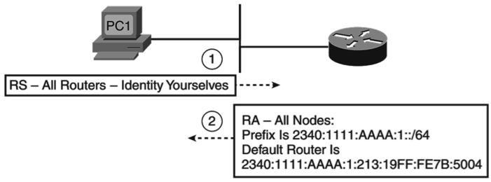
Обнаружение маршрутизатора, подключённого к сегменту локальной сети, используется для получения узлом адреса IPv6 с помощью процедуры stateless address autoconfiguration (SLAAC), которую ещё называют Stateless DHCP.
______________
UPD 5/05/14: Как верно заметил коллега в комментарии, следует различать SLAAC и Stateless DHCP. В нашем с Максимом тексте пропущено важно е слово «ОШИБОЧНО». Помните, как в учебнике по философии говорилось, что нельзя выдирать цитату из контекста, а то получится «Было бы ошибкой думать, что (цитата)» 
Итого, верно было бы написать: «stateless address autoconfiguration (SLAAC), которую в некоторой литературе ОШИБОЧНО называют Stateless DHCP.»
Приношу свои извинения за недосмотр и введение в заблуждение
______________
(продолжение в виде маршрутизации, туннелирования и VRF — здесь).
Статья написана Максимом Климановым (foxnetwork.ru, я — соавтор), который попросил меня опубликовать ее для широкого круга читателей.
Cisco routers do not have Internet Protocol version 6 (IPv6) routing enabled by default. So how do we enable IPv6 on a router?
- First, enable IPv6 routing on a Cisco router using the ‘ipv6 unicast-routing’ global configuration command. This command globally enables IPv6 and must be the first command executed on the router.
- Configure the IPv6 global unicast address on an interface using the ‘ipv6 address address/prefix-length [eui-64]’ command. After you enter this command, the link local address will be automatically derived. If you omit the ‘eui-64’ parameter, you will need to configure the entire address manually.
IPv6 Configuration and Verification
Here is an IPv6 configuration example:
R1(config)#ipv6 unicast-routing
R1(config)#int Gi0/0
R1(config-if)#ipv6 address 2001:0BB9:AABB:1234::/64 eui-64
We can verify the IP configuration and IP settings using the ‘show ipv6 interface Gi0/0’ command:
R1#show ipv6 interface Gi0/0
GigabitEthernet0/0 is up, line protocol is up
  IPv6 is enabled, link-local address is FE80::201:42FF:FE65:3E01
  No Virtual link-local address(es):
  Global unicast address(es):
    2001:BB9:AABB:1234:201:42FF:FE65:3E01, subnet is 2001:BB9:AABB:1234::/64 [EUI]
  Joined group address(es):
    FF02::1
    FF02::2
    FF02::1:FF65:3E01
  MTU is 1500 bytes
  ....
From the output above, we can verify the following:
- The link local IPv6 address has been automatically configured. Link local addresses begin with FE80::/10, and the interface ID is used for the rest of the address. Because the interface’s MAC address is 00:01:42:65:3E01, the calculated address is FE80::201:42FF:FE65:3E01.IPv6 hosts check that their link local IP addresses are unique and not in use by reaching out to the local network using Neighbor Discovery Process (NDP).
- The global IPv6 address has been created using the modified EUI-64 method. Remember that IPv6 global addresses begin with 2000::/3. So in our case, the IPv6 global address is 2001:BB9:AABB:1234:201:42FF:FE65:3E01.
We will also create an IPv6 address on another router. This time, we will enter the whole address:
R2(config-if)#ipv6 address 2001:0BB9:AABB:1234:1111:2222:3333:4444/64
Notice that the IPv6 address is in the same subnet configured on R1 (2001:0BB9:AABB:1234/64). We can test the connectivity between the devices using the ‘ping’ command for IPv6:
R1#ping ipv6 2001:0BB9:AABB:1234:1111:2222:3333:4444

Type escape sequence to abort.
Sending 5, 100-byte ICMP Echos to 2001:0BB9:AABB:1234:1111:2222:3333:4444, timeout is 2 seconds:
!!!!!
Success rate is 100 percent (5/5), round-trip min/avg/max = 0/0/0 ms
As you can see from the output above, the devices can communicate with each other. So that’s how to enable IPv6 on router. IPv6 addresses and the default gateway can also be configured on hosts automatically using SLAAC and DHCPv6. DNS servers are still required to be able to reach the Internet.
Download our Free CCNA Study Guide PDF for complete notes on all the CCNA 200-301 exam topics in one book.
We recommend the Cisco CCNA Gold Bootcamp as your main CCNA training course. It’s the highest rated Cisco course online with an average rating of 4.8 from over 30,000 public reviews and is the gold standard in CCNA training:

Table of Contents
IPv6 Configuration
IPv6 is the new version of the most important Network Layer Protocol IP. With this new IP version, IPv6, beside different features, some configuration differencies are also coming. In this lesson, we will focus on these IPv6 Configuration Steps, IPv6 Configuration on Cisco devices. We will use the below Packet Tracer topology for our IPv6 Config.
You can download Packet Tracer IPv6 Lab, in Packet Tracer Labs page.
In this configuration lesson, we will follow the below IPv6 Configuration steps:
- Enable IPv6 Globally
- Enable IPv6 on Interface
- Configure EUI-64 Format Global Unicast Address
- Configure Manual Global Unicast Address
- IPv6 Ping
- Manual Link Local Address Configuration
- Auto IPv6 Address Configuration
- Enable DHCPv6 Client
- IPv6 Verification Commands
So, let’s go to the IPv6 Configuration steps and configure IPv6 for Cisco routers.
Enable IPv6 Globally
After going to the configuration mode with “configure terminal” command, to enable IPv6 on a Cisco router, “ipv6 unicast-routing” command is used. With this Cisco command, IPv6 is enabled globally on the router. This can be used before both interface configurations and IPv6 Routing Protocol configurations.
Router 1# configure terminal
Router 1(config)# ipv6 unicast-routing
Router 2# configure terminal
Router 2(config)# ipv6 unicast-routing
Enable IPv6 on Interface
After enabling IPv6 globally, we should enable IPv6 under the Interfaces. To enable IPv6 under an interface, we will use “ipv6 enable” command. Let’s enable IPv6 on two interfaces of each router.
Router 1 (config)# interface FastEthernet0/0
Router 1 (config-if)# ipv6 enable
Router 1 (config-if)# no shutdown
Router 1 (config)# interface FastEthernet0/1
Router 1 (config-if)# ipv6 enable
Router 1 (config-if)# no shutdown
Router 2 (config)# interface FastEthernet0/0
Router 2 (config-if)# ipv6 enable
Router 2 (config-if)# no shutdown
Router 2 (config)# interface FastEthernet0/1
Router 2 (config-if)# ipv6 enable
Router 2 (config-if)# no shutdown
Configure EUI-64 Format Global Unicast Address
EUI-64 format is the IPv6 format used to create IPv6 Global Unicast Addresses. It is a specific format that we have also talked about before. With this format, basically, interface id of the whole IPv6 adderess is ceated with the help of the MAC address. After that, this created interface id is appended to the network id.
To configure an interface with EUI-64 format (Extended Unique Identifier), firstly we will go under the interface, then we will use “ip address ipv6-address/prefix-length eui-64” command. Here, our IPv6 address and prefix-length are 2001:AAAA:BBBB:CCCC::/64. The real EUI-64 Global Unicast Address will be created with this address and MAC address after IPv6 configuration.
Router 1 (config)# interface FastEthernet0/0
Router 1(config-if)# ipv6 address 2001:AAAA:BBBB:CCCC::/64 eui-64
Router 1(config-if)# end
Let’s check the IPv6 address that is created with EUI-64 format with “show ipv6 interface brief” command.
Router 1# show ipv6 interface brief
FastEthernet0/0 [up/up]
FE80::2E0:B0FF:FE0E:7701
2001:AAAA:BBBB:CCCC:2E0:B0FF:FE0E:7701
FastEthernet0/1 [up/up]
FE80::2E0:B0FF:FE0E:7702
Vlan1 [administratively down/down]
unassigned
Configure Manual Global Unicast Address
If we do not use EUI-64 format address, we have to write the whole IPv6 Address to the configuration line. Let’s configure Gigabit Ethernet 0/0 interface of Router 2 manually.
Router 2 (config)# interface FastEthernet0/0
Router 2 (config-if)# ipv6 address 2001:AAAA:BBBB:CCCC:1234:1234:1234:1234/64
Router 2(config-if)# end
Here, both of these directly connected interfaces are in the same subnet, the Network ID is same (2001:AAAA:BBBB:CCCC::/64).
Let’s check the IPv6 address that we have manually assigned with “show ipv6 interface brief” command.
Router 2# show ipv6 interface brief
FastEthernet0/0 [up/up]
FE80::206:2AFF:FE15:BD01
2001:AAAA:BBBB:CCCC:1234:1234:1234:1234
FastEthernet0/1 [administratively up/up]
FE80::206:2AFF:FE15:BD02
Vlan1 [administratively down/down]
unassigned
IPv6 Ping
To check the connectivity between two node, we use ping. As IPv4, with IPv6, we also use ping, but this time it is called IPv6 Ping. The format of IPv6 Ping is a little difference than IPv4 Ping. These differences are the format of the used IP address and the used keywords. With IPv6 Ping, “ping ipv6” keywords are used before the destination IPv6 address.
Here, we will ping from Router 1 GigabitEthernet0/0 interface to Router 2 GigabitEthernet0/0 interface.
Router 1# ping ipv6 2001:AAAA:BBBB:CCCC:1234:1234:1234:1234
Type escape sequence to abort.
Sending 5, 100-byte ICMP Echos to 2001:AAAA:BBBB:CCCC:1234:1234:1234:1234, timeout is 2 seconds:
!!!!!
Success rate is 100 percent (5/5), round-trip min/avg/max = 0/0/1 ms
To check the configured IPv6 Address, we can use “show ipv6 interface interface-name” command.
Router 1# show ipv6 interface FastEthernet0/0
FastEthernet0/0 is up, line protocol is up
IPv6 is enabled, link-local address is FE80::2E0:B0FF:FE0E:7701
No Virtual link-local address(es):
Global unicast address(es):
2001:AAAA:BBBB:CCCC:2E0:B0FF:FE0E:7701, subnet is 2001:AAAA:BBBB:CCCC::/64 [EUI]
Joined group address(es):
FF02::1
FF02::2
FF02::1:FF0E:7701
MTU is 1500 bytes
ICMP error messages limited to one every 100 milliseconds
ICMP redirects are enabled
ICMP unreachables are sent
ND DAD is enabled, number of DAD attempts: 1
ND reachable time is 30000 milliseconds
ND advertised reachable time is 0 (unspecified)
ND advertised retransmit interval is 0 (unspecified)
ND router advertisements are sent every 200 seconds
ND router advertisements live for 1800 seconds
ND advertised default router preference is Medium
Hosts use stateless autoconfig for addresses.
Router 2# show ipv6 interface FastEthernet0/0
FastEthernet0/0 is up, line protocol is up
IPv6 is enabled, link-local address is FE80::206:2AFF:FE15:BD01
No Virtual link-local address(es):
Global unicast address(es):
2001:AAAA:BBBB:CCCC:1234:1234:1234:1234, subnet is 2001:AAAA:BBBB:CCCC::/64
Joined group address(es):
FF02::1
FF02::2
FF02::1:FF15:BD01
FF02::1:FF34:1234
MTU is 1500 bytes
ICMP error messages limited to one every 100 milliseconds
ICMP redirects are enabled
ICMP unreachables are sent
ND DAD is enabled, number of DAD attempts: 1
ND reachable time is 30000 milliseconds
ND advertised reachable time is 0 (unspecified)
ND advertised retransmit interval is 0 (unspecified)
ND router advertisements are sent every 200 seconds
ND router advertisements live for 1800 seconds
ND advertised default router preference is Medium
Hosts use stateless autoconfig for addresses.
Here, with ipv6 ping, there are some options that we can use. These are given below:
ping ipv6 [hostname | ip_address] [repeat repeat-count | size datagram-size | source [interface-name | source-address]
- repeat : Ping packet count. The default ping repeat value is 5.
- size : Datagram size. The default value ping size is 56 bytes.
- source : Source Address of the ping. Default value is None.
So if we would like to send 10 IPv6 ping packet with 200 byte datagrams from 2001:AAAA:BBBB:CCCC:1234:1234:1234:1234 to 2001:AAAA:BBBB:CCCC:1111:2222:3333:4444, we will use the below command:
Router 2 # ping ipv6 2001:AAAA:BBBB:CCCC:1111:2222:3333:4444 repeat 10 size 200 source 2001:AAAA:BBBB:CCCC:1234:1234:1234:1234
Manual Link Local Address Configuration
To configure a Link Locak address manually, we use “ipv6 address link-local ipv6-address” command. Here, we should write an IPv6 address in the range of Link Local addresses. If you would like to learn more about a Link Local Address, you can check Link Local Address lesson.
Let’s configure GigabitEthernet0/1 interface of Router 1 with Link Local Address FE80::AAAA:BBBB:CCCC:DDDD. Here, there is no need to write a prefix length but we will add link-local keyword at the end of the command.
Router 1 (config)# interface FastEthernet0/1
Router 1 (config-if)# ipv6 address FE80::AAAA:BBBB:CCCC:DDDD link-local
Router 1 (config-if)# end
Let’s check the manually configure ipv6 Link-Local address with “show ipv6 interface brief” command.
Router 1# show ipv6 interface brief
FastEthernet0/0 [up/up]
FE80::2E0:B0FF:FE0E:7701
2001:AAAA:BBBB:CCCC:2E0:B0FF:FE0E:7701
FastEthernet0/1 [administratively down/down]
FE80::AAAA:BBBB:CCCC:DDDD
Vlan1 [administratively down/down]
unassigned
Auto IPv6 Address Configuration
IPv6 Addresses can be configured automatically. This is one of the most important characteristics coming with IPv6. For IPv6 Auto configuration, we will use “ipv6 address autoconfig” command. Let’s use it on Router 2 on GigabitEthernet0/1.
Router 2 (config)# interface FastEthernet0/1
Router 2 (config-if)# ipv6 address autoconfig
Router 2 (config-if)# end
This type of IPv6 address configuration is Sateless Auto Configuration.
Let’s check the Autoconfigured Link-Local ipv6 address with “show ipv6 interface brief” command.
Router 2# show ipv6 interface brief
FastEthernet0/0 [up/up]
FE80::206:2AFF:FE15:BD01
2001:AAAA:BBBB:CCCC:1234:1234:1234:1234
FastEthernet0/1 [up/down]
FE80::206:2AFF:FE15:BD02
Vlan1 [administratively down/down]
unassigned
Let’s ping from Router 2 to Router 1 to test this second interfaces’ ipv6 connection.
Router 2# ping ipv6 FE80::AAAA:BBBB:CCCC:DDDD
Output Interface: FastEthernet0/1
Type escape sequence to abort.
Sending 5, 100-byte ICMP Echos to FE80::AAAA:BBBB:CCCC:DDDD, timeout is 2 seconds:
!!!!!
Success rate is 100 percent (5/5), round-trip min/avg/max = 0/0/1 ms
Enable DHCPv6 Client
To enable DHCPv6 Client function on an interface, we use “ipv6 address dhcp” command under this interface. With this command, interface gets its IPv6 address form the DHCPv6 server. Let’s enable DHCPv6 on GigabitEthernet0/2 of Router 2.
Router 1 (config)# interface FastEthernet0/1
Router 1 (config-if)# ipv6 address dhcp
Router 1 (config)# end
To verify DHCPv6 enabled interfaces, we can use “show ipv6 dhcp interface” command.
Router 1 # show ipv6 dhcp interface
IPv6 Verification Commands
To verify IPv6 Configuration, we can use different show commands. These IPv6 show commands are given below
- To check IPv6 interface configuration and status we use “show ipv6 interface interface-id”.
Router 1# show ipv6 interface FastEthernet0/0
FastEthernet0/0 is up, line protocol is up
IPv6 is enabled, link-local address is FE80::2E0:B0FF:FE0E:7701
No Virtual link-local address(es):
Global unicast address(es):
2001:AAAA:BBBB:CCCC:2E0:B0FF:FE0E:7701, subnet is 2001:AAAA:BBBB:CCCC::/64 [EUI]
Joined group address(es):
FF02::1
FF02::2
FF02::1:FF0E:7701
MTU is 1500 bytes
ICMP error messages limited to one every 100 milliseconds
ICMP redirects are enabled
ICMP unreachables are sent
ND DAD is enabled, number of DAD attempts: 1
ND reachable time is 30000 milliseconds
ND advertised reachable time is 0 (unspecified)
ND advertised retransmit interval is 0 (unspecified)
ND router advertisements are sent every 200 seconds
ND router advertisements live for 1800 seconds
ND advertised default router preference is Medium
Hosts use stateless autoconfig for addresses.
- To check IPv6 neighbor cache entries we use “show ipv6 neighbors”.
