Всем привет!
Сегодня создадим простейшую сеть, топология которой представлена на рисунке.
Топология
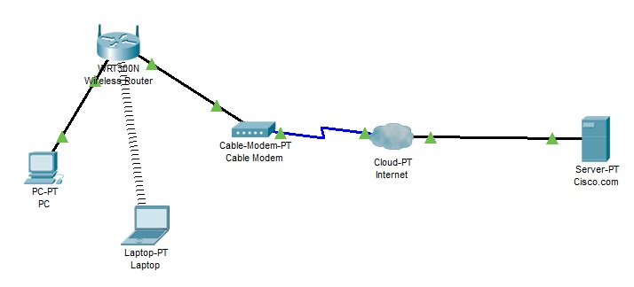
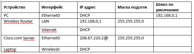
Таблица адресации
Задачи
- Создание простейшей сети в рабочей области логической топологии
- Конфигурирование сетевых устройств
- Тестирование связи между сетевыми устройствами
Создание простейшей сети в рабочей области логической топологии
Запускаем Packet Tracer
а. Запустите Packet Tracer на вашем ПК или ноутбуке.
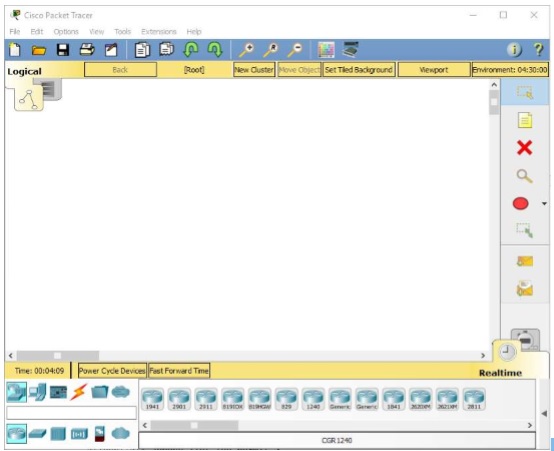
Дважды щелкните значок «Пакет трассировщика» на рабочем столе или перейдите в каталог, содержащий исполняемый файл Packet Tracer, и запустите пакетный трассировщик. Пакет Tracer должен открываться с пустой рабочей областью логической топологии по умолчанию, как показано на рисунке.
Выстраиваем топологию
а. Добавьте сетевые устройства в рабочее пространство.
Используя окно выбора устройства, добавьте сетевые устройства в рабочее пространство, как показано на диаграмме топологии.
Чтобы поместить устройство в рабочую область, сначала выберите тип устройства из окна «Выбор типа устройства». Затем щелкните нужную модель устройства в окне «Выбор устройства». Наконец, нажмите на местоположение в рабочей области, чтобы поместить ваше устройство в это место. Если вы хотите отменить свой выбор, нажмите на значок «Отмена» для этого устройства. Кроме того, вы можете щелкнуть и перетащить устройство из окна «Выбор конкретного устройства» в рабочее пространство.
б. Измените отображаемые имена устройств сети.
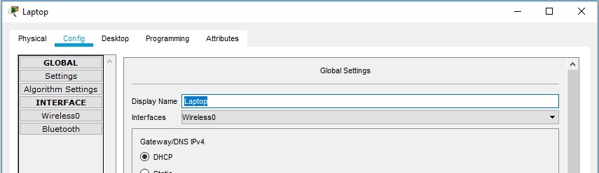
Чтобы изменить отображаемые имена сетевых устройств, щелкните значок устройства в рабочем пространстве Packet Tracer Logical, затем щелкните вкладку Config в окне конфигурации устройства. На вкладке «Конфигурация» введите новое имя устройства в поле «Отображаемое имя», как показано на рисунке.
в. Добавить физическую проводку между устройствами в рабочей области
Используя поле выбора устройства, добавьте физическую проводку между устройствами в рабочей области, как показано на диаграмме топологии.
Для подключения к беспроводному маршрутизатору ПК понадобится медный прямой кабель. Выберите медный прямой кабель в окне «Выбор устройства» и прикрепите его к интерфейсу FastEthernet0 на ПК и интерфейсу Ethernet 1 беспроводного маршрутизатора.
Для подключения беспроводного маршрутизатора к кабельному модему потребуется медный прямой кабель. Выберите медный прямой кабель в окне «Выбор устройства» и прикрепите его к Интернет-интерфейсу беспроводного маршрутизатора и интерфейсу порта 1 кабельного модема.
Внимание: не перепутайте медный прямой кабель (чёрная сплошная линия) с медным перекрёстным кабелем (чёрная прерывистая линия). В случае ошибки порты не поднимутся (линки не загорятся зелёным цветом).
Для подключения к интернет-облако кабельный модем потребуется коаксиальный кабель. Выберите коаксиальный кабель в окне «Выбор устройства» и прикрепите его к интерфейсу порта 0 кабельного модема и коаксиальному интерфейсу интернет-облака.
Для подключения к серверу Cisco.com для облака Interne необходим медный прямой кабель. Выберите медный прямой кабель в окне «Выбор устройства» и прикрепите его к интерфейсу Ethernet облака Интернета и интерфейсу FastEthernet0 на сервере Cisco.com.
Настройка сетевых устройств
Настройте беспроводной маршрутизатор
a. Создание беспроводной сети на беспроводном маршрутизаторе
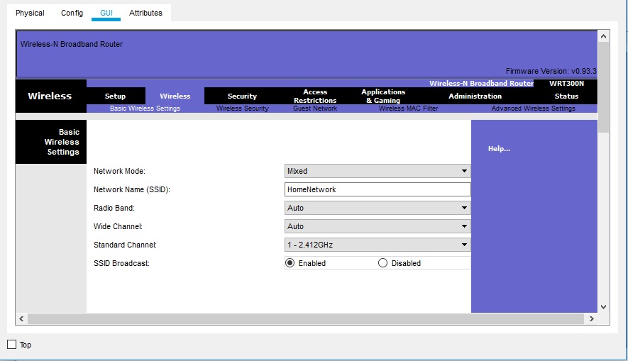
Нажмите значок Wireless Router на рабочем пространстве Packet Tracer Logical, чтобы открыть окно конфигурации устройства. В окне конфигурации Wireless Router нажмите вкладку GUI, чтобы просмотреть параметры конфигурации для Wireless Router. Затем щелкните вкладку Wireless в графическом интерфейсе, чтобы просмотреть настройки беспроводной сети. Единственным параметром, который необходимо изменить по умолчанию, является имя сети (SSID). Здесь введите имя «HomeNetwork», как показано на рисунке.
б. Настройка подключения к Интернету на беспроводном маршрутизаторе
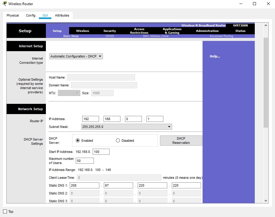
Нажмите вкладку «Настройка» в графическом интерфейсе Wireless Router. В настройках сервера DHCP убедитесь, что выбрана кнопка «Включено» и настройте статический IP-адрес DNS-сервера как 208.67.220.220, как показано на рисунке.
с. Перейдите на вкладку «Сохранить настройки».
Настройте ноутбук
a. Настройка портативного компьютера для доступа к беспроводной сети
Нажмите значок «Ноутбук» на рабочем месте Packet Tracer Logical, а в окнах конфигурации ноутбука выберите вкладку «Физические». На вкладке «Физик» вам нужно будет удалить медный модуль Ethernet и заменить его на модуль Wireless WPC300N. Для этого сначала выключите ноутбук, нажав кнопку питания на боковой панели ноутбука. Затем удалите установленный в данный момент медный модуль Ethernet, щелкнув модуль на боковой панели ноутбука и перетащите его в панель MODULES слева от окна ноутбука. Затем установите модуль Wireless WPC300N, щелкнув по нему в панели MODULES и перетащив его в пустой порт модуля на стороне ноутбука. Включите ноутбук снова, снова нажав кнопку питания ноутбука. С установленным беспроводным модулем следующая задача — подключить ноутбук к беспроводной сети.
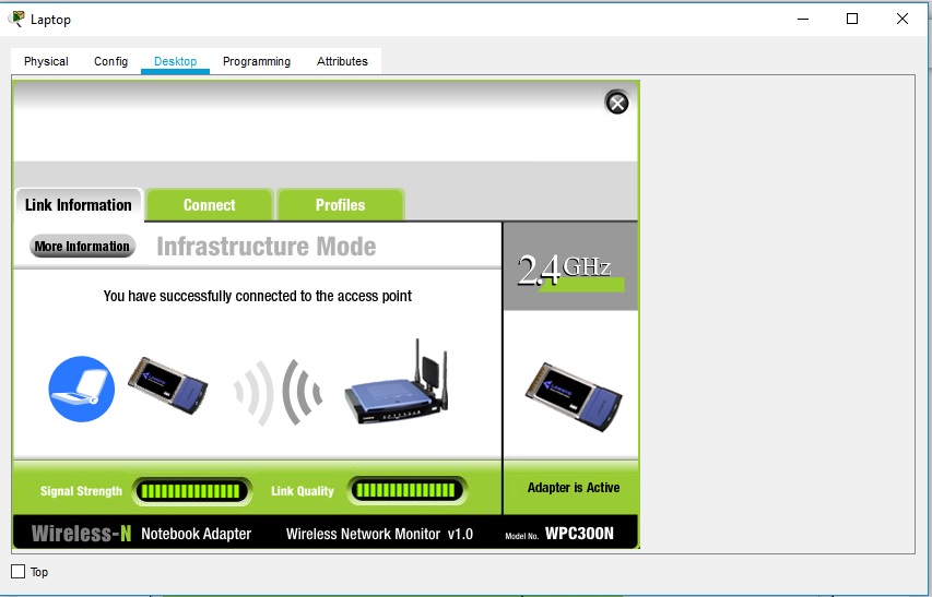
Перейдите на вкладку «Рабочий стол» в верхней части окна конфигурации ноутбука и выберите значок «Беспроводная сеть ПК». После того, как параметры адаптера ноутбука Wireless-N видны, выберите вкладку «Подключить». Беспроводная сеть «HomeNetwork» должна быть видна в списке беспроводных сетей, как показано на рисунке. Выберите сеть и нажмите вкладку «Подключиться», расположенную под информацией о сайте.
Настройте ПК
a. Конфигурирование ПК для проводной сети
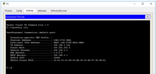
Нажмите значок ПК на рабочем пространстве Packet Tracer Logical и выберите вкладку «Рабочий стол», а затем значок «Конфигурация IP». В окне IP-конфигурации выберите переключатель DCHP, как показано на рисунке, чтобы ПК использовал DCHP для приема IPv4-адреса с беспроводного маршрутизатора. Закройте окно настройки IP.
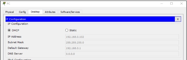
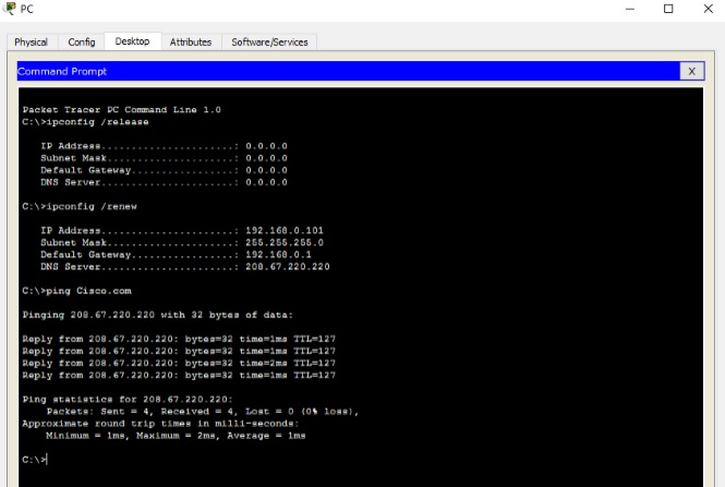
Нажмите на значок командной строки. Убедитесь, что ПК получил IPv4-адрес, выпустив команду ipconfig / all из команды, как показано на рисунке. ПК должен получить IPv4-адрес в диапазоне 192.168.0.x.
Настройте облако Интернета
a. При необходимости установите сетевые модули.
Нажмите значок «Интернет-облако» в рабочей области «Трассировщик пакетов» и затем перейдите на вкладку «Физические». Для облачного устройства потребуется два модуля, если они еще не установлены. PT-CLOUD-NM-1CX, который предназначен для подключения кабельного модема и PT-CLOUD-NM-1CFE, который предназначен для подключения медного Ethernet-кабеля. Если эти модули отсутствуют, отключите физические облачные устройства, нажав на кнопку питания и перетащите каждый модуль на пустой порт модуля на устройстве, а затем снова включите устройство.
б. Определите тип поставщика.
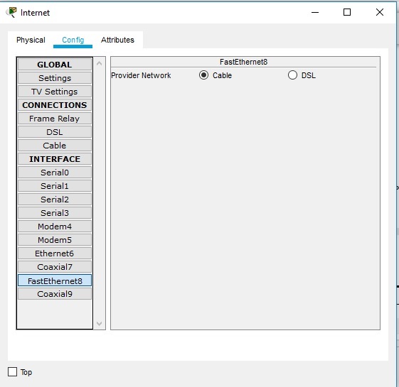
На вкладке «Конфигурация» нажмите «FastEthernet8» в «INTERFACE» на левой панели. В окне конфигурации FastEthernet8 выберите «Кабель» в качестве сети поставщика, как показано на рисунке.
с. Идентификация портов From и To
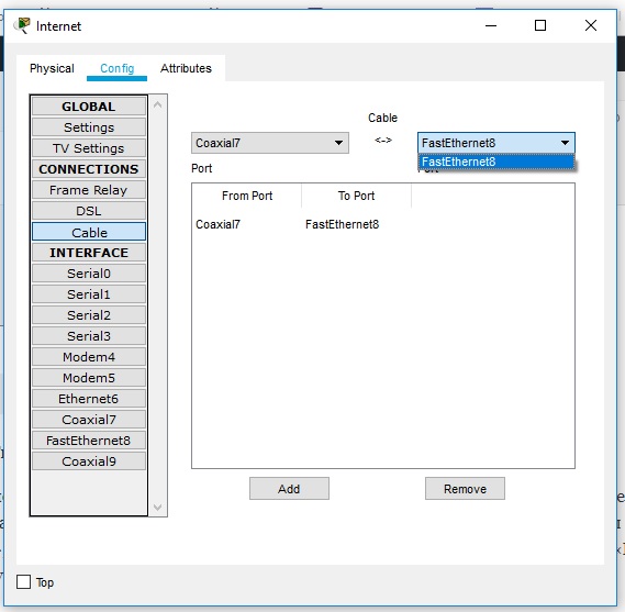
Перейдите на вкладку «Конфигурация» в окне «Облако». В левой панели нажмите «Кабель» под разъемами CONNECTIONS. В первом раскрывающемся списке выберите Coaxial7, а во втором выпадающем списке выберите «FastEthernet8», затем нажмите кнопку Add, чтобы добавить их как «От порта» и «В порт», как показано на рисунке.
Настройте сервер Cisco.com
a. Настройте сервер Cisco.com как сервер DHCP
Нажмите значок сервера Cisco.com в рабочем пространстве Packet Tracer Logical и выберите вкладку «Службы». Выберите DHCP из списка «УСЛУГИ» на левой панели.
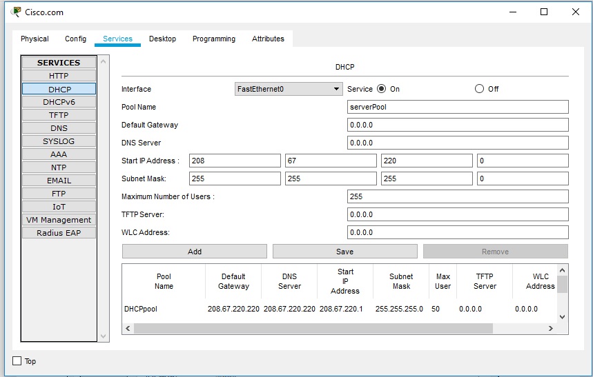
В окне конфигурации DHCP настройте DHCP, как показано на рисунке, со следующими настройками.
- Нажмите «Вкл.», Чтобы включить службу DCHP.
- Имя пула: DHCPpool
- Шлюз по умолчанию: 208.67.220.220
- DNS-сервер: 208.67.220.220
- Запуск IP-адреса: 208.67.220.1
- Маска подсети 255.255.255.0
- Максимальное количество пользователей: 50
Нажмите «Добавить», чтобы добавить пул
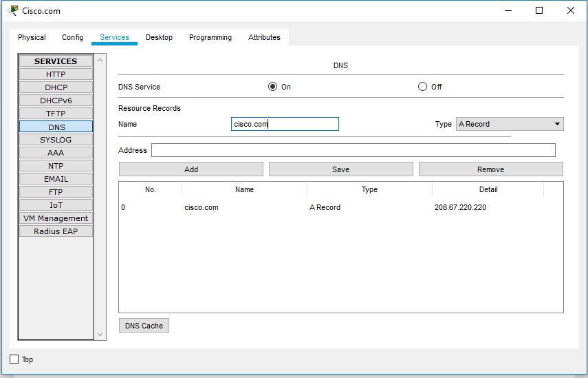
б. Настройте сервер Cisco.com как DNS-сервер для предоставления имени домена для разрешения адреса IPv4.
На вкладке «Службы» выберите DNS из служб, перечисленных на левой панели.
Настройте службу DNS, используя следующие настройки, как показано на рисунке.
- Нажмите «Вкл.», Чтобы включить службу DNS:
- Имя: Cisco.com
- Тип: A Запись
Адрес: 208.67.220.220
Нажмите «Добавить», чтобы добавить настройки службы DNS
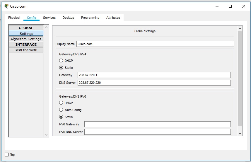
с. Настройте глобальные настройки сервера Cisco.com.
Выберите вкладку «Конфигурация». Нажмите «Настройки» в левой панели. Настройте глобальные настройки сервера следующим образом:
- Выберите Статический
- Шлюз: 208.67.220.1
- DNS-сервер: 208.67.220.220
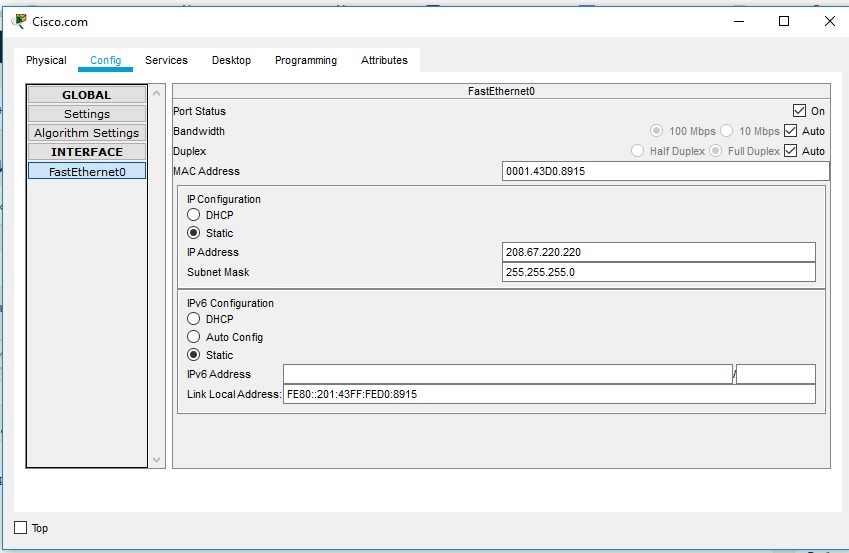
д. Настройте параметры интерфейса FastEthernet0 сервера Cisco.com.
Нажмите «FastEthernet» в левой панели вкладки «Конфигурация». Настройте параметры интерфейса FastEthernet на сервере следующим образом:
- Выберите «Статический» при настройке IP-адреса
- IP-адрес: 208.67.220.220
- Маска подсети: 255.255.255.0
Проверка подключения
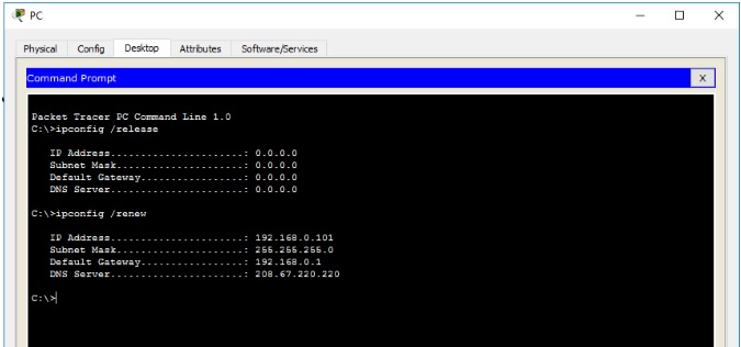
Обновите настройки IPv4 на ПК
a. Убедитесь, что ПК получает информацию о конфигурации IPv4 от DHCP.
Нажмите на ПК в рабочем пространстве Packet Tracer Logical, а затем выберите вкладку Desktop в окне конфигурации ПК.
Нажмите значок командной строки
б. Проверить подключение к серверу Cisco.com с ПК
Из командной строки, выдающей команду ping Cisco.com. Для возврата ping может потребоваться несколько секунд. Необходимо получить четыре ответа, как показано на рисунке.
Файл с готовой лабораторной работой можно скачать по ссылке Готовая лабораторная работа. Потребуется версия Cisco Packet Tracer 7.2
Чтобы научиться настраивать NAT переходите по ссылке Лабораторная работа №8 | Настройка NAT
Если у вас возникли трудности с выполнением задания, вы всегда сможете найти толкового исполнителя здесь: work-zilla.com

Кол-во просмотров: 68398
вот сама топология сети
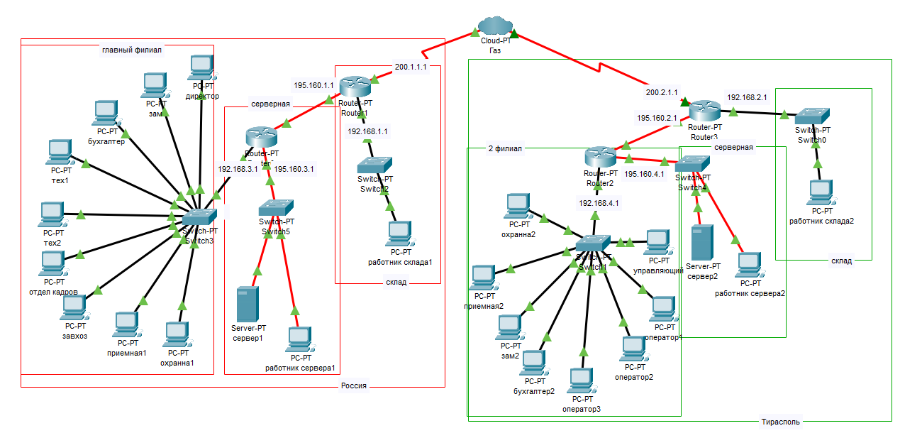
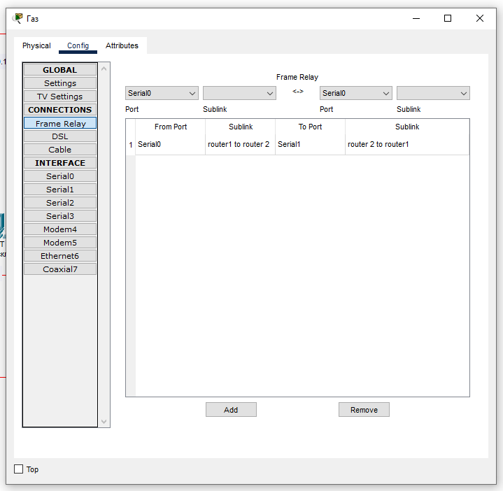
и мне надо через облако Frame Relay провести маршрутизацию я это сделал вот:
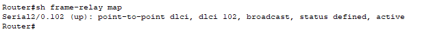
и прописал маршрутизацию роутера к облаку:
но пинговать 2 филиала не может не могу понять что не так сделал помогите плиз с решением данной проблемы укажите гдк я прошляпился
-
Вопрос задан
-
739 просмотров
Configuring Cisco Cloud APIC Using the Setup Wizard
Configuring and Deploying Inter-Site Connectivity
Before you can begin to configure and deploy your Cloud APIC, you must first configure and deploy your Cisco ACI Multi-Site and your on-premises Cisco ACI, if you are connecting an on-premises site to cloud sites. The
actual configuration for each varies, depending on your requirements
and setup. If you are connecting an on-premises site to cloud sites,
you will also need to configure and deploy an on-premises IPsec
termination device to connect to the Cisco Cloud Services Router
1000Vs deployed by Cloud APIC in AWS. See Components of Extending Cisco ACI Fabric to the Public Cloud for more
information.
Following are documents that will aid you in the process of configuring and deploying these components:
-
Cisco ACI documentation: Available at Cisco Application Policy Infrastructure Controller (APIC) documentation, such as Operating Cisco Application Centric Infrastructure and Cisco APIC Basic Configuration Guide, Release 4.0(1).
-
Cisco ACI Multi-Site: Available at Cisco ACI Multi-Site documentation, such as Cisco ACI Multi-Site Orchestrator Installation and Upgrade Guide, Release 2.0(1).
-
Cisco Cloud Services Router 1000V: Available at Cisco CSR 1000v documentation.
Gathering On-Premises Configuration Information
 Note |
You do not have to gather any information in this section if you |
Use the following list to gather and record the necessary on-premises configuration
information that you will need throughout these procedures to set up
your Cisco Cloud APIC:
|
Necessary On-Premises Information |
Your Entry |
|---|---|
|
On-premises IPsec device public IP address |
|
|
IPsec termination device to CSR OSPF area |
|
|
On-premises APIC IP address |
|
|
Cisco Cloud APIC IP address |
Understanding Limitations for Number of Sites, Regions and CSRs
Throughout this document, you will be asked to decide on various configurations for sites, regions and CSRs. Following is
a list of limitations for each that you should keep in mind as you’re making configuration decisions for each.
Sites
The total number of sites that you can have with Cloud APIC depends on the type of configuration that you are setting up:
-
On-premises ACI site-to-cloud site configuration (AWS or Azure): ACI Multi-Site multi-cloud deployments support any combination of one or two cloud sites (AWS or Azure) and one or two on-premises
sites for a maximum total of four sites. The connectivity options are:-
Hybrid-Cloud: On-premises-to-single cloud site connectivity
-
Hybrid Multi-Cloud: On-premises-to-multiple cloud sites connectivity
-
-
Multi-Cloud: Cloud site-to-cloud site connectivity (AWS or Azure): ACI Multi-Site multi-cloud deployments support a combination of any two cloud sites (AWS, Azure, or both) for a total of
two sites. -
Cloud First: Single-Cloud Configuration: ACI Multi-Site multi-cloud deployments support a single cloud site (AWS or Azure)
Regions
Within each site, you can have a maximum of four regions per site. Cloud APIC can manage multiple regions as a single site.
CSRs
You can have a certain number of CSRs within some regions, with the following limitations:
-
You must have at least one region with CSRs deployed to have inter-VNET (Azure), inter-VPC (AWS), or inter-VRF communications.
-
You do not have to have CSRs in every region.
-
For regions with CSRs deployed to enable connectivity, the number of CSRs that you can deploy in each region varies:
-
For cloud site-to-cloud site configurations (Multi-Cloud):
-
CSRs can be deployed on a maximum of two managed regions.
-
A maximum of two CSRs per managed region is supported, for a total of four CSRs per cloud site.
-
-
For on-premises-to-cloud site (Hybrid-Cloud or Hybrid Multi-Cloud) or for single-cloud (Cloud First) configurations :
-
CSRs can be deployed on all four managed regions.
-
The number of CSRs supported per managed region varies, depending on the release:
-
For releases prior to 5.1(2), a maximum of four CSRs per managed region is supported, for a total of 16 CSRs per cloud site.
-
For Release 5.1(2) and later, a maximum of eight CSRs per managed region is supported, for a total of 32 CSRs per cloud site.
For more information on increasing the number of CSRs, see the Cloud APIC for AWS User Guide.
-
-
-
Locating the Cloud APIC IP Address
These procedures describe how to locate the IP address for the Cloud APIC through the AWS site.
Procedure
| Step 1 |
Go to the AWS account for the Cloud APIC infra tenant. |
||
| Step 2 |
Click the Services link at the top of the screen, then click the EC2 link. The EC2 Dashboard screen appears. |
||
| Step 3 |
In the EC2 Dashboard screen, you should see text displaying the number of running instances in the Resources area (for example, 1 Running Instances). Click this running instances link. The Instances screen appears. |
||
| Step 4 |
Choose the Cloud APIC instance named Capic-1 and copy the IP address that is shown in the IPv4 Public IP column. This is the Cloud APIC IP address that you will use to log into the Cloud APIC.
|
Configuring Cisco Cloud APIC Using the Setup Wizard
Follow the procedures in this topic to set up the cloud infrastructure configuration for your Cloud APIC. Cloud APIC will automatically deploy the required AWS constructs and the necessary CSRs.
Before you begin
Following are the prerequisites for this task:
-
You have met the requirements that are outlined in Requirements for Extending the Cisco ACI Fabric to the Public Cloud before proceeding with the tasks in this section.
-
You have successfully completed the procedures that are provided in Configuring the Cloud Formation Template Information for the Cisco Cloud APIC.
Procedure
| Step 1 |
In the AWS site, get the Cloud APIC IP address. See Locating the Cloud APIC IP Address for those instructions. |
||||||
| Step 2 |
Open a browser window and, using the secure version of HTTP (https://), paste the IP address into the URL field, then press Return to access this Cloud APIC. For example, https://192.168.0.0. If you see a message asking you to Ignore Risk and Accept Certificate, accept the certificate to continue. |
||||||
| Step 3 |
Enter the following information in the login page for the Cloud APIC:
|
||||||
| Step 4 |
Click Login at the bottom of the page.
The Welcome to Cloud APIC setup wizard page appears. |
||||||
| Step 5 |
Click Begin Set Up. The Let’s Configure the Basics page appears, with these areas to be configured:
|
||||||
| Step 6 |
In the DNS Servers row, click Edit Configuration. The DNS and NTP page appears. |
||||||
| Step 7 |
In the DNS and NTP page, add the DNS, if necessary, and NTP servers.
|
||||||
| Step 8 |
When you have finished adding the DNS and NTP servers, click Save and Continue. The Let’s Configure the Basics page appears again. |
||||||
| Step 9 |
In the Region Management row, click Begin. The Region Management page appears. |
||||||
| Step 10 |
Verify that the Cloud APIC home region is selected. The region that you selected in Step 2 in Deploying the Cloud APIC in AWS is the home region and should be selected already in this page. This is the region where the Cloud APIC is deployed (the region that will be managed by Cloud APIC), and will be indicated with the text cAPIC deployed in the Region column. |
||||||
| Step 11 |
Select additional regions if you want the Cloud APIC to manage additional regions, and to possibly deploy CSRs to have inter-VPC communication and Hybrid-Cloud, Hybrid Multi-Cloud, The CSR can manage four regions, including the home region where Cloud APIC is deployed. A Cloud APIC can manage multiple cloud regions as a single site. In a typical Cisco ACI configuration, a site represents anything that can be managed by an APIC cluster. If a Cloud APIC cluster manages two regions, those two regions are considered a single site by Cisco ACI. The following options are available on the row for any region that you select:
|
||||||
| Step 12 |
When you have selected all the appropriate regions, click Next at the bottom of the page. The General Connectivity page appears. |
||||||
| Step 13 |
Enter the following information on the General Connectivity page.
|
||||||
| Step 14 |
Click the appropriate button, depending on whether you are configuring inter-site connectivity or not.
|
||||||
| Step 15 |
Enter the following information in the Inter-Site Connectivity page:
|
||||||
| Step 16 |
When you have entered all the necessary information on this page, click Save and Continue at the bottom of the page. The Let’s Configure the Basics page appears again. |
||||||
| Step 17 |
In the Smart Licensing row, click Register. The Smart Licensing page appears. |
||||||
| Step 18 |
Enter the necessary information in the Smart Licensing page. Cisco Smart Licensing is a unified license management system that manages software licenses across Cisco products. To register
To learn more about Smart Software Licensing, visit https://www.cisco.com/go/smartlicensing. |
||||||
| Step 19 |
Click Register at the bottom of the page if you entered the necessary licensing information on this page, or click Continue in Evaluation Mode if you want to continue in evaluation mode instead. The Summary page appears. |
||||||
| Step 20 |
Verify the information on the Summary page, then click Close. At this point, you are finished with the internal network connectivity configuration for your Cloud APIC. If this is the first time that you are deploying your Cloud APIC, this process might take quite a bit of time, possibly 30 minutes or so before the process is successfully completed. |
What to do next
Determine if you are managing additional sites along with the Cisco Cloud APIC site or not:
-
If you are managing additional sites (an on-premises site or cloud sites) along with the Cisco Cloud APIC site (if you selected
the Inter-Site Connectivity option in the Region Management page), go to Managing Cisco Cloud APIC Through Cisco ACI Multi-Site. -
If you are setting up a Cloud First configuration, where you are not managing any other sites along with the Cisco Cloud APIC
site (if you selected only the Cloud Routers option in the Region Management page), you will not need to use the Cisco ACI Multi-Site for additional configurations. However, you will have additional
configurations that you must perform in the Cisco Cloud APIC GUI in this case. Use the Global Create option in the Cisco Cloud
APIC GUI to configure the following components:-
Tenant
-
Application Profile
-
EPG
See Navigating the Cisco Cloud APIC GUI and Configuring Cisco Cloud APIC Components for more information.
-
Verifying the Cisco Cloud APIC Setup Wizard Configurations
Use the procedures in this topic to verify that the configuration information that you entered in the Cloud APIC Setup Wizard
are applied correctly.
Procedure
In Cisco Cloud APIC, verify the following settings:
-
Under Cloud Resources, click on Regions and verify that the regions that you selected are shown as managed in the Admin State column.
-
Under Infrastructure, click on Inter-Region Connectivity and verify the information in this screen is correct.
-
Under Infrastructure, click on On Premises Connectivity and verify the information in this screen is correct.
-
Click on Dashboard and use the information in the On Premises Connectivity Status and the Inter-Region Connectivity Status
boxes to verify that the setup wizard and tunnel configurations were done properly.
What to do next
Complete the multi-site configuration using the procedures provided in Managing Cisco Cloud APIC Through Cisco ACI Multi-Site.
Локальное администрирование соединителя управления
После успешной установки соединителя ваш шлюз будет готов к использованию с Webex Calling. При необходимости можно обновить некоторые параметры коннектора, используя параметры, доступные в меню сценария:
|
Вы можете перезапустить скрипт в любое время, используя следующую команду: tclsh загрузочная флэш-память: /gateway_connector /gateway_onboarding .tcl . |
===============================================================
Webex Managed Gateway Connector
===============================================================
Options
s : Display Status Page
v : View and Modify Cloud Connector Settings
e : Enable Guestshell
d : Disable Guestshell
l : Collect Logs
r : Clear Logs
u : Uninstall Connector
q : Quit
===============================================================
Select an option from the menu:
Включить гостевую оболочку
Включите облачный коннектор с помощью e: Enable Guestshell пункт меню. Это изменяет статус коннектора с INACTIVE до ACTIVE.
Отключить гостевую оболочку
Отключите облачный коннектор с помощью d: Disable Guestshell пункт меню. Это изменяет статус коннектора с ACTIVE до INACTIVE.
Удалить коннектор
Удалите облачный коннектор с помощью u: Uninstall Connector пункт меню. При этом будут удалены все данные в контейнере гостевой оболочки и все конфигурации, связанные с облачным соединителем.
Сбор журналов
Соберите журналы с помощью l: Collect Logs пункт меню. Система отображает место хранения этих журналов после сбора журналов.
|
Если у вас есть активное обращение в службу обращение в службу поддержки Cisco TAC, вы можете прикрепить журналы непосредственно к запрос службы на обслуживание с помощью команды скопировать загрузочную флэш-память: / guest-share /<log-filename> scp: //<case-number> :<cxd-token> @ cxd.cisco.com . |
Ниже приведен пример команды:
vcubeprod#copy bootflash:/guest-share/gateway_webex_cloud_logs_2022114090628.tar.gz scp://123456789:a1b2c3d4e5@cxd.cisco.comОчистить журналы
Очистите все файлы журналов на устройстве, используя r: Clear Logs пункт меню. При этом будут удалены все существующие журналы, кроме последних журналов сценария Tcl и коннекторов.
Просмотр и изменение настроек Cloud Connector
Внесите следующие изменения в существующие настройки облачного коннектора с помощью v: View and Modify Cloud Connector Settings пункт меню.
===============================================================
                Webex Managed Gateway Connector
===============================================================
		Script Version         : 2.0.2
		Hostname/IP Addr       : 10.65.125.188
		DNS Server(s)          : 10.64.86.70
		Gateway Username       : lab
		External Interface     : GigabitEthernet1
		Proxy Hostname/IP Addr : proxy-wsa.esl.cisco.com:80
===============================================================
             Options
               c :  Update Gateway Credentials
               e :  Update External Interface
               p :  Update Proxy Details
               n :  Update DNS Server
               k :  Update Connector Package Verification Key
               l :  Modify log level for Cloud Connector
               h :  Go to home menu
               q :  Quit

===============================================================
                        Select an option from the menu: c
Обновить учетные данные шлюза
Обновите имя пользователя и пароль шлюза с помощью c: Update Gateway Credentials пункт меню.
Обновить внешний интерфейс
Измените интерфейс, к которому привязан коннектор, и IP-адрес коннектора с помощью v: View and Modify Cloud Connector Settings пункт меню.
Обновить сведения о прокси
Вы можете выполнять следующие задачи с помощью p: Update Proxy Details пункт меню:
-
i: Update Proxy IP and Port -
c: Update Proxy Credentials -
r: Remove Proxy Credentials -
a: Remove All Proxy Details -
h: Go to home menu
Ключ проверки пакета соединителя обновления
Если у вас возникла техническая проблема, и инженер службы поддержки попросил вас заменить ключ проверки пакета, загрузите новый шлюз-webex-connector.gpg файл в загрузочная флэшка: /gateway_connector / и используйте k: Update Connector Package Verification Key пункт меню для проверки.
Изменение уровня журнала для соединителя управления
Измените уровень ведения журнала для коннектора с помощью l: Modify log level for Cloud Connector пункт пункт меню, а затем выберите один из следующих вариантов:
===============================================
		  Number      Log Level
===============================================
		    1           DEBUG
		    2           INFO
		    3           WARNING
		    4           ERROR
		    5           CRITICAL
===============================================