Виртуальные локальные сети (VLAN) — это мощный инструмент для разделения физической сети на логические сегменты. Они позволяют группировать устройства в сети согласно их функциональности, обеспечивая повышенную безопасность и эффективность сети.
Настройка VLAN на роутере Cisco Packet Tracer позволяет создать виртуальные LAN-сегменты и определить настройки для каждого сегмента. В этом пошаговом руководстве мы рассмотрим процесс создания VLAN на роутере с использованием Cisco Packet Tracer и настроим соответствующие устройства.
Перед началом настройки VLAN, убедитесь, что у вас есть правильный образ Cisco IOS для роутера на Cisco Packet Tracer. Также убедитесь, что версия Cisco Packet Tracer поддерживает функционал VLAN. Если у вас возникнут любые проблемы, обратитесь к документации Cisco или обратитесь к опытным специалистам по сетевым технологиям.
Теперь, когда мы готовы, давайте двигаться дальше и начнем настраивать VLAN на роутере на Cisco Packet Tracer, следуя пошаговым инструкциям в нашем руководстве.
Содержание
- Что такое VLAN и зачем его настраивать на Cisco Packet Tracer на роутере
- Шаг 1: Создание VLAN
- Создание нового VLAN на Cisco Packet Tracer на роутере
- Шаг 2: Назначение портов VLAN
- Назначение портов к созданному VLAN на Cisco Packet Tracer на роутере
- Шаг 3: Настройка VLAN на интерфейсе роутера
- Конфигурирование VLAN на интерфейсе роутера на Cisco Packet Tracer
- Шаг 4: Проверка настроек
- Проверка работоспособности настроенных VLAN на Cisco Packet Tracer на роутере
Что такое VLAN и зачем его настраивать на Cisco Packet Tracer на роутере
VLAN настраивается на роутере с помощью программы Cisco Packet Tracer, которая предоставляет возможность виртуальной настройки сетей. Настраивая VLAN на роутере, можно создавать виртуальные группы устройств, которые находятся на разных физических сегментах сети, но могут обмениваться данными между собой.
Основные преимущества настройки VLAN на Cisco Packet Tracer на роутере:
- Изоляция трафика: VLAN позволяет разнести различные группы устройств по разным сетям, что позволяет изолировать трафик между ними. Это повышает безопасность сети и предотвращает возможные атаки.
- Управление трафиком: VLAN позволяет контролировать и оптимизировать трафик в сети. Виртуальные группы позволяют создавать отдельные сегменты для различных типов трафика, таких как голосовые данные или данные высокой пропускной способности, что повышает производительность сети.
- Увеличение гибкости: VLAN позволяет легко изменять конфигурацию сети в зависимости от потребностей. Различные виртуальные группы устройств могут быть добавлены, удалены или модифицированы без проблем, что делает сеть более гибкой.
- Управление устройствами: VLAN позволяет настроить доступ к определенным устройствам или группам устройств в сети. Это позволяет более эффективно управлять ресурсами сети и управлять безопасностью.
Использование VLAN на Cisco Packet Tracer на роутере является важным шагом в настройке современной сети. Оно позволяет более эффективно управлять и контролировать работу сети, повышая безопасность и производительность.
Шаг 1: Создание VLAN
Перед настройкой VLAN необходимо убедиться, что роутер в вашей сети поддерживает данную функцию.
Для создания VLAN на Cisco Packet Tracer выполните следующие шаги:
- Откройте программу Cisco Packet Tracer и создайте новый проект.
- Перетащите на поле проекта маршрутизатор из панели устройств.
- Щелкните правой кнопкой мыши на маршрутизаторе и выберите «Configure».
- Перейдите на вкладку «VLAN» и нажмите кнопку «Add» для добавления нового VLAN.
- Введите идентификатор VLAN и название VLAN в соответствующие поля.
- Установите тип VLAN как «Static» и нажмите «OK».
- Повторите шаги 4-6 для создания необходимого количества VLAN.
- Нажмите «Apply» для сохранения настроек VLAN.
Поздравляю! Вы только что создали VLAN на Cisco Packet Tracer. Теперь можно перейти к настройке портов маршрутизатора для работы с VLAN.
Создание нового VLAN на Cisco Packet Tracer на роутере
Для создания нового VLAN на Cisco Packet Tracer на роутере необходимо выполнить следующие шаги:
- Зайдите в конфигурационный режим роутера с помощью команды
enable. - Перейдите в режим основной конфигурации командой
configure terminal. - Введите команду
vlan vlan_id, гдеvlan_id— идентификатор создаваемого VLAN. - Нажмите клавишу
Enterи введите командуname vlan_name, гдеvlan_name— имя для создаваемого VLAN. - Нажмите клавишу
Enterи введите командуexit, чтобы выйти из конфигурационного режима VLAN. - Сохраните конфигурацию командой
writeилиcopy running-config startup-config.
После выполнения этих шагов новый VLAN будет создан на Cisco Packet Tracer на роутере.
Шаг 2: Назначение портов VLAN
После создания VLAN необходимо назначить порты на роутере для работы с соответствующими VLAN. Это позволит установить соединение между VLAN и физическими портами на роутере. Чтобы назначить порт VLAN, выполните следующие действия:
- Откройте конфигурацию роутера с помощью команды
conf t. - Перейдите в режим настройки интерфейса VLAN с помощью команды
interface vlan [номер VLAN]. - Назначьте IP-адрес VLAN с помощью команды
ip address [IP-адрес] [маска подсети]. - Активируйте VLAN с помощью команды
no shutdown. - Назначьте порт VLAN с помощью команды
switchport access vlan [номер VLAN]. - Повторите этот процесс для каждого порта, который вы хотите назначить на определенный VLAN.
После завершения этих шагов порты VLAN будут настроены на роутере и готовы к использованию. Теперь вы можете передавать данные между VLAN с помощью этих портов.
Назначение портов к созданному VLAN на Cisco Packet Tracer на роутере
После создания VLAN на Cisco Packet Tracer, необходимо назначить соответствующие порты для работы с этим VLAN на роутере. Назначение портов позволяет установить соединение между устройствами в этом VLAN.
Для назначения портов к созданному VLAN на роутере, необходимо выполнить следующие шаги:
- Зайти в режим конфигурации роутера с помощью команды
enableи ввести пароль, если он установлен. - Перейти в режим конфигурации интерфейса командой
configure terminal. - Выбрать интерфейс, который будет назначен для VLAN, с помощью команды
interface [тип интерфейса номер интерфейса]. - Назначить VLAN для выбранного интерфейса с помощью команды
switchport access vlan [номер VLAN]. - Сохранить настройки командой
writeилиcopy running-config startup-config.
После выполнения этих шагов, выбранный интерфейс будет назначен для работы с созданным VLAN на Cisco Packet Tracer на роутере. Не забудьте сохранить настройки, чтобы они сохранялись после перезагрузки устройства.
Шаг 3: Настройка VLAN на интерфейсе роутера
После создания VLAN на коммутаторе, следующим шагом будет настройка соответствующих VLAN на интерфейсе роутера. Для этого выполните следующие действия:
| Шаг | Команда | Описание |
|---|---|---|
| 1 | Войдите в режим настройки интерфейса: | configure terminal |
| 2 | Выберите нужный интерфейс: | interface [номер интерфейса] |
| 3 | Настройте соответствующую VLAN для интерфейса: | switchport mode access |
| 4 | Присвойте номер VLAN: | switchport access vlan [номер VLAN] |
| 5 | Завершите конфигурацию: | exit |
Повторите эти шаги для каждого интерфейса роутера, на котором нужно настроить VLAN.
После завершения настройки VLAN на интерфейсе роутера, коммутатор и роутер должны быть подключены друг к другу. Теперь VLAN-трафик будет проходить через роутер, что позволит разделить сеть на несколько виртуальных LAN.
Конфигурирование VLAN на интерфейсе роутера на Cisco Packet Tracer
Для настройки VLAN на интерфейсе роутера на Cisco Packet Tracer следуйте следующим шагам:
- Откройте программу Cisco Packet Tracer и создайте новый проект.
- Добавьте роутер на рабочее пространство, перетащив его из панели инструментов.
- Щелкните правой кнопкой мыши на интерфейсе роутера, на который вы хотите настроить VLAN, и выберите «Настроить».
- В открывшемся окне настройки интерфейса выберите вкладку «Виртуальная локальная сеть (VLAN) — VLAN».
- Установите флажок «Включено» рядом с VLAN и введите идентификатор VLAN в поле «VLAN ID».
- Нажмите «Применить» для сохранения изменений.
После выполнения этих шагов VLAN будет настроен на выбранном интерфейсе роутера. Вы можете продолжить настройку других параметров VLAN, таких как настройка портов коммутатора, добавление компьютеров в VLAN и т.д.
Шаг 4: Проверка настроек
После завершения настройки VLAN-ов на роутере Cisco, следует проверить правильность выполненных действий. Для этого можно использовать несколько способов.
1. Проверка интерфейсов VLAN
Воспользуйтесь командой show vlan brief на консоли роутера, чтобы просмотреть текущую конфигурацию VLAN-ов. Вы увидите список всех созданных VLAN-ов, а также соответствующий номер и статус интерфейсов VLAN. Убедитесь, что интерфейсы VLAN находятся в состоянии «up» и сопоставлены с правильными VLAN-ами.
2. Проверка сетевых соединений
Проверьте соединение между устройствами, подключенными к VLAN-ам, с помощью команды ping. Например, для проверки связи между компьютерами, подключенными к разным VLAN-ам, можно использовать команду ping с IP-адресом компьютера в другом VLAN. Если пинг проходит успешно, значит, настройка VLAN-ов выполнена корректно.
3. Проверка интерфейсов маршрутизатора
Используйте команду show interfaces на консоли роутера, чтобы получить информацию о состоянии и конфигурации интерфейсов маршрутизатора. Убедитесь, что интерфейсы VLAN отображаются и находятся в состоянии «up». Проверьте также, что правильно настроены IP-адреса на каждом интерфейсе VLAN.
После проверки настроек и убеждения в их правильности, вы можете быть уверены, что VLAN-ы на роутере Cisco настроены корректно и готовы к использованию.
Проверка работоспособности настроенных VLAN на Cisco Packet Tracer на роутере
После настройки VLAN на Cisco Packet Tracer на роутере важно проверить их работоспособность. Для этого можно выполнить несколько простых шагов:
- Подключите компьютеры к соответствующим портам на коммутаторах, задействованных в настройке VLAN.
- Настройте IP-адреса для каждого компьютера. Убедитесь, что IP-адреса компьютеров принадлежат тому же подсети, что и соответствующие VLAN.
- Проверьте связность между компьютерами в пределах одной и той же VLAN. Для этого выполните команду ping с IP-адреса одного компьютера на IP-адрес другого компьютера.
- Проверьте связность между компьютерами из разных VLAN. Для этого выполните команду ping с IP-адреса компьютера одного VLAN на IP-адрес компьютера из другого VLAN.
- Убедитесь, что связность работает корректно и все компьютеры в VLAN могут свободно обмениваться данными.
Проверка работоспособности настроенных VLAN на Cisco Packet Tracer на роутере позволит убедиться, что все настройки выполнены правильно и VLAN функционируют так, как задумано. Если во время проверки возникают проблемы, стоит перепроверить настройки VLAN и IP-адреса компьютеров, а также убедиться, что виртуальные интерфейсы VLAN на роутере работают корректно.
⇒ CISCO ⇐
Voice(Asterisk\Cisco)
Microsoft
Powershell
Python
SQL\T-SQL
FreeBSD and Nix
1С
Общая
WEB Разработка
ORACLE SQL \ JAVA
Мото
Стрельба, пневматика, оружие
Саморазвитие и психология
Продолжаем серию статей по cisco.
Ссылка на первую http://snakeproject.ru/rubric/article.php?art=packet_tracer_1
В данной статье мы построим более сложную сеть с dhcp, vlan`ами, и статической маршрутизацией.
dhcp нужен как сервер раздачи ip адресов по сети.
vlan разделяют сеть на логические сегменты(повышают безопастность, разделяют сегменты доступа по сети)
статическая маршрутизация определяется в виде записей маршрутов для прохождения пакетов по сети.
Скачайте проект для packet tracer файл
Открываем и смотрим настройки:
Видео выложу на своем канале YouTube
Комментарии пользователей
Анонимам нельзя оставоять комментарии, зарегистрируйтесь!
Код обмена баннерами


© Snakeproject.ru создан в 2013 году.
При копировании материала с сайта — оставьте ссылку.
Welcome to this tutorial! This is a simple step by step guide of configuring VLAN and interVLAN routing on a Cisco switch. But just before get into configurations , let’s have a brief overview of what’s a VLAN.
What is a VLAN?
A Virtual LAN (VLAN) is simply a logical LAN, just as its name suggests. VLANs have similar characteristics with those of physical LANs, only that with VLANs, you can logically group hosts even if they are physically located on separate LAN segments.
We treat each VLAN as a separate subnet or broadcast domain. For this reason, to move packets from one VLAN to another, we have to use a router or a layer 3 switch.
VLANs are configured on switches by placing some interfaces into one broadcast domain and some interfaces into another. For this tutorial, we’ll configure 2 VLANs on a switch. We’ll then proceed and configure a router to enable communication between the two VLANs.
So then,
- In Cisco Packet Tracer, create the network topology as shown below:
2. Create 2 VLANs on the switch: VLAN 10 and VLAN 20. You can give them custom names.
Switch#config terminal
Switch(config)#vlan 10
Switch(config-vlan)#name SALES
Switch(config-vlan)#vlan 20
Switch(config-vlan)#name IT
3. Assign switch ports to the VLANs. Remember each VLAN is viewed as separate broadcast domain.
And just before you configure, have in mind that switch ports could be either access or trunk.
- An access port is assigned to a single VLAN . These ports are configured for switch ports that connect to devices with a normal network card, for example a PC in a network.
- A trunk port on the other hand is a port that can be connected to another switch or router. This port can carry traffic of multiple VLANs.
So in our case, we’ll configure switch interfaces fa 0/1 through fa 0/4 as access ports to connect to our PCs. Here, interfaces fa 0/1 and fa 0/2 are assigned to VLAN 10 while interfaces fa 0/3 and fa 0/4 are assigned to VLAN 20.
Switch Interface fa0/5 will be configured as trunk port, as it will be used to carry traffic between the two VLANs via the router.
Switch>enable
Switch#config terminal

Switch(config)#int fa0/1
Switch(config-if)#switchport mode access
Switch(config-if)#switchport access vlan 10

Switch(config-if)#int fa0/2
Switch(config-if)#switchport mode access
Switch(config-if)#switchport access vlan 10

Switch(config-if)#int fa0/3
Switch(config-if)#switchport mode access
Switch(config-if)#switchport access vlan 20

Switch(config-if)#int fa0/4
Switch(config-if)#switchport mode access
Switch(config-if)#switchport access vlan 20
Worth noting: We could have configured all the above interfaces as access ports using interface range command as shown below:
Switch(config-if)#int range fa0/1-4
Switch(config-if-range)#switchport mode access
In the above commands, we have specified an interface range and then proceeded to configure all the ports specified as access ports.
Interface fa0/5 is configured as trunk and will be used to for inter-VLAN communication.
Switch(config)#int fa 0/5
Switch(config-if)#switchport mode trunk
The next thing is to:
4 . Assign static IP addresses to the four PCs which are located in the separate VLANs. PC1 and PC2 fall in VLAN 10 while PC3 and PC4 fall in VLAN 20.
PC1 IP address 192.168.1.10 Subnet mask 255.255.255.0 Default gateway 192.168.1.1
PC2: IP address 192.168.1.20 Subnet mask 255.255.255.0 Default gateway 192.168.1.1
PC3: IP address 192.168.2.10 Subnet mask 255.255.255.0 Default gateway 192.168.2.1
PC4: IP address 192.168.2.20 Subnet mask 255.255.255.0 Default gateway 192.168.2.1
And now it’s very clear that we treat a VLAN just like a physical LAN when assigning IP addresses.
At this point let’s try to test connectivity within VLANs and between VLANs
To test communication between hosts in the same VLAN:
Ping PC2 from PC1 both in VLAN 10. Ping test should be successful.
To test connectivity between hosts in different VLANs:
Ping PC3 in VLAN 20 from PC1 in VLAN 10. Ping here will definitely fail. Why? Because inter-VLAN routing is not yet enabled. Hope you can see how we’ve used VLANs to place the hosts into two logical networks which can be viewed as separate broadcast domains.
Now, in order to allow the hosts in the two VLANs to communicate, we need to do something extra. And you can guess what. We’ll configure the router to permit inter-VLAN communication. Let’s do that right away.
5. Configure inter-VLAN routing on the router
We’ll configure the router so that it will enable communication between the two vlans via a single physical interface. How is this made possible? We’ll divide the single physical interface on the router into logical interfaces (sub interfaces). Each sub-interface will then serve as a default gateway for each of the VLANs. This scenario is called router on a stick (R.O.A.S) and will allow the VLANs to communicate through the single physical interface.
Wort noting: We can’t assign an IP address to the router’s physical interface that we have subdivided into logical sub-interfaces. We’ll instead assign IP addresses to the sub interfaces.
So let’s do router configurations:
Router>enable
Router#config terminal

Router(config)#int fa0/0
Router(config-if)#no shutdown

Router(config-if)#int fa0/0.10
Router(config-subif)#encapsulation dot1q 10
Router(config-subif)#ip add 192.168.1.1 255.255.255.0
Router(config-subif)#

Router(config-subif)#int fa0/0.20
Router(config-subif)#encapsulation dot1q 20
Router(config-subif)#ip add 192.168.2.1 255.255.255.0
As you can notice from above, the routers physical interface fa0/0 was subdivided into two sub-interfaces( fa0/0.10 and fa0/0.20) , which are then configured as trunk interfaces and given IP addresses.
Finally,
6. Test inter-VLAN connectivity.
Here we’ll test connectivity between computers in different VLANs . Don’t forget that its the router that enables inter-VLAN routing.
Ping PC3 in VLAN 20 from PC1 in VLAN 10. If everything is well configured, then ping should work perfectly.
And that’s all!
Hope this article was useful to you. Comment to help improve it.
All the best.
See also:
- Configuring Switch Port Security in Packet Tracer
In this article, you will learn-
- 1 How to Configure VLAN in Cisco Packet Tracer
-
-
-
- 1.0.0.0.1 Office 1 Switch
-
-
- 1.1 Assigning VLAN Membership
-
-
- 1.1.0.0.1 Office 1 Switch
- 1.1.0.0.2 Office 2 Switch
- 1.1.0.0.3 Office 3 Switch
-
- 1.1.1 Testing VLAN configuration
-
-
- 2 Configure Router on Stick
- 2.1 Spanning Tree Protocol (STP)
- 3 READ NEXT
How to Configure VLAN in Cisco Packet Tracer: This instructional exercise discloses how to make and allot VLAN, VLAN Membership (Static and Dynamic), Router on Stick and Spanning Tree Protocol (STP) in detail with down to earth models in parcel tracer. Figure out how to make and oversee VLAN in Cisco switch bit by bit.
Make a training lab in bundle tracer as appeared in the following the figure of download pre-made practice lab from the second piece of this instructional exercise,
Making VLAN
By and by lab organize Office1 Switch is arranged as VTP Server. Office2 and Office3 switches are arranged as VTP customers. We just need to make VLANs in VTP Server. VTP Server will spread this data to all VTP customers naturally.
VLAN VLAN number command is used to create the VLAN.
Office 1 Switch
S1(config)#vlan 10
S1(config-vlan)#exit
S1(config)#vlan 20
S1(config-vlan)#exit
S1(config)#
Assigning VLAN Membership
VLAN can be assigned statically or dynamically. CCNA exam only includes static methods; therefore we will also use static methods to assign VLAN membership. switch port access VLAN [vlan number ] command is used to assign VLAN to the interface. The following commands will assign VLANs to the interfaces.
Office 1 Switch
S1(config)#interface fastEthernet 0/1
S1(config-if)#switchport access vlan 10
S1(config-if)#interface fastEthernet 0/2
S1(config-if)#switchport access vlan 20
Office 2 Switch
S2(config)#interface fastEthernet 0/1
S2(config-if)#switchport access vlan 10
S2(config-if)#interface fastEthernet 0/2
S2(config-if)#switchport access vlan 20
Office 3 Switch
S3(config)#interface fastEthernet 0/1
S3(config-if)#switchport access vlan 10
S3(config-if)#interface fastEthernet 0/2
S3(config-if)#switchport access vlan 20


We have effectively doled out VLAN enrollment. It's a great opportunity to test our setup. To test this design, we will utilize the ping order. ping order is utilized to test the network between two gadgets. According to our design, gadgets from the same VLAN can impart. Gadgets from various VLANs must not have the option to speak with one another without the switch.
Testing VLAN configuration
Access PC’s command prompt to test VLAN configuration. Double click PC-PT and click Command Prompt
We have two VLAN configurations VLAN 10 and VLAN 20. Let’s test VLAN 10 first. In VLAN 10 we have three PCs with IP addresses 10.0.0.2, 10.0.0.3 and 10.0.0.4. These PCs must be able to communicate with each other. At this point PCs from VLAN 10 should not be allowed to access PCs from VLAN 20. VLAN 20 also has three PCs 20.0.0.2, 20.0.0.3 and 20.0.0.4.
We have successfully implemented VLAN 10 now test VLAN 20.
Same as VLAN 10, PCs from VLAN 20 must be able to communicate with other PCs of the same VLAN while they should not be able to access VLAN 10.
Congratulations we have successfully achieved one more milestone of this article.
Configure Router on Stick
Typically routers are configured to receive data on one physical interface and forward that data from another physical interface based on its configuration. Each VLAN has a layer 3 address that should be configured as the default gateway address on all its devices. In our scenario, we reserved IP address 10.0.0.1 for VLAN 10 and 20.0.0.1 for VLAN 20.
With the default configuration, we need two physical interfaces on the router to make this intra VLAN communication. Due to the price of the router, it’s not a cost-effective solution to use a physical interface of the router for each VLAN. Usually, a router has one or two Ethernet interfaces. For example, if we have 50 VLANs, we would need nearly 25 routers in order to make intra VLANs communications. To deal with the situation we use Router on Stick.
A router on Stick is a router that supports trunk connection and has an ability to switch frames between the VLANs on this trunk connection. On this router, a single physical interface is sufficient to make communication between our both VLANs.
Access command prompt of Router
To configure Router on Stick we have to access the CLI prompt of Router. Click Router and Click CLI from menu items and Press Enter key to access the CLI
Run following commands in the same sequence to configure Router on Stick
Router>enable
Router#configure terminal
Enter configuration commands, one per line.  End with CNTL/Z.
Router(config)#interface fastEthernet 0/0
Router(config-if)#no ip address
Router(config-if)#no shutdown
Router(config-if)#exit
Router(config)#interface fastEthernet 0/0.10
Router(config-subif)#encapsulation dot1Q 10
Router(config-subif)#ip address 10.0.0.1 255.0.0.0
Router(config-subif)#exit
Router(config)#interface fastEthernet 0/0.20
Router(config-subif)#encapsulation dot1Q 20
Router(config-subif)#ip address 20.0.0.1 255.0.0.0
Router(config-subif)#exit
In the above configuration, we broke up a single physical interface [FastEthernet 0/0] into two logical interfaces, known as sub-interfaces. The router supports up to 1000 interfaces including both physical and logical.
- By default interface, the link works as an access link. We need to change it into a trunk link. encapsulation commands specify the trunk type and associate VLAN with sub-interface.
- In the next step, we assigned the IP address to our sub-interface.
That’s all configuration we need to switch VLANs. Now we can test different VLAN communications. To test intra VLANs communication open command prompt of PC and ping the PC of other VLAN.
PC [10.0.0.3] from VLAN 10 can now access PC [20.0.0.2] from VLAN 20.
Spanning Tree Protocol (STP)
STP is a Layer 2 protocol, used for removing loops. For backup purposes, we typically create backup links for important resources. In our scenario, all offices have backup links that create loops in topology. STP automatically removes layer 2 loops. STP multicasts frame that contains information about switch interfaces. These frames are called BPDU (Bridge Protocol Data Units). The switch uses BPDUs to learn network topology. If it found any loop, it will automatically remove that. To remove the loop, STP disables port or ports that are causing it.
| Switch(config)#vtp password password | Set VTP password. Password is case sensitive |
| Switch#show vtp status | Display VTP status including general information |
| Switch#show vtp counters | Show VTP counters of switch |
| Switch(config-if) #switchport mode trunk | Change interface mode in Trunk |
| Switch(config)#vlan 10 | Create VLAN and associate number ID 10 with it |
| Switch(config-vlan)#name Sales | Assign name to VLAN |
| Switch(config-vlan)#exit | Return in Global configuration mode from VLAN configuration mode |
| Switch(config)#interface fastethernet 0/1 | Enter in interface configuration mode |
| Switch(config-if)#switchport mode access | Set interface link type to access link |
| Switch(config-if)#switchport access vlan 10 | Assign this interface to VLAN 10 |
| Switch#show vlan | Displays VLAN information |
| Switch#show vlan brief | Displays VLAN information in short |
| Switch#show vlan id 10 | Displays information VLAN ID 10 only |
| Switch#show vlan name sales | Displays information about VLAN named sales only |
| Switch(config)#interface fastethernet 0/8 | Enter in Interface configuration mode |
| Switch(config-if)#no switchport access vlan 10 | Removes interface from VLAN 10 and reassigns it to the default VLAN – VLAN 1 |
| Switch(config-if)#exit | Move back to Global configuration mode |
| Switch(config)#no vlan 10 | Delete VLAN 10 from VLAN database |
| Switch#copy running-config startup-config | Saves the running configuration in NVRAM |
Use this configured topology for cross-checking if you are not getting the same output after following all steps.
READ NEXT
CCNA Fresher Basic Interview Questions with Answer
CCNA Interview Questions & Answers
How to Secure your Cisco Router with Passwords
The most effective method to Configure MS SQL Server to Listen on a given port
This is about How to Configure VLAN in Cisco Packet Tracer
Thanks for reading! We hope you found this tutorial helpful and we would love to hear your feedback in the Comments section below. And show us what you’ve learned by sharing your projects with us.
The VLAN (Virtual LAN) structure is used to divide the physical network topology into logical network segments. When VLANs are configured, the physical network environment provides better performance and better network management.
How to Create and Configure VLANs on Cisco Switch with Packet Tracer
In a physical network environment, you can allocate users in a specific location to logical areas with VLANs. For example, if a 3-floor company has a finance department on each floor, you can configure a VLAN so that you can communicate these departments between floors.
In the actual scenario, users do not take notice of this change when you do this. By simply grouping the existing network logically, you get more network performance, and you can also restrict data traffic between VLAN groups.
You can now follow the steps below to create and configure VLANs on Switches using the simulator software.
Step 1
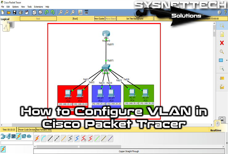
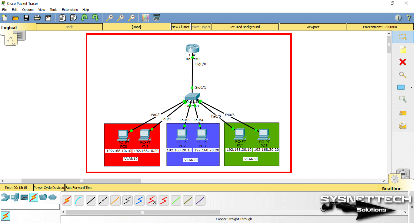
First, add a Router, Switch, and six PCs to the Packet Tracer workspace to create a network topology as shown in the image below.
Step 2
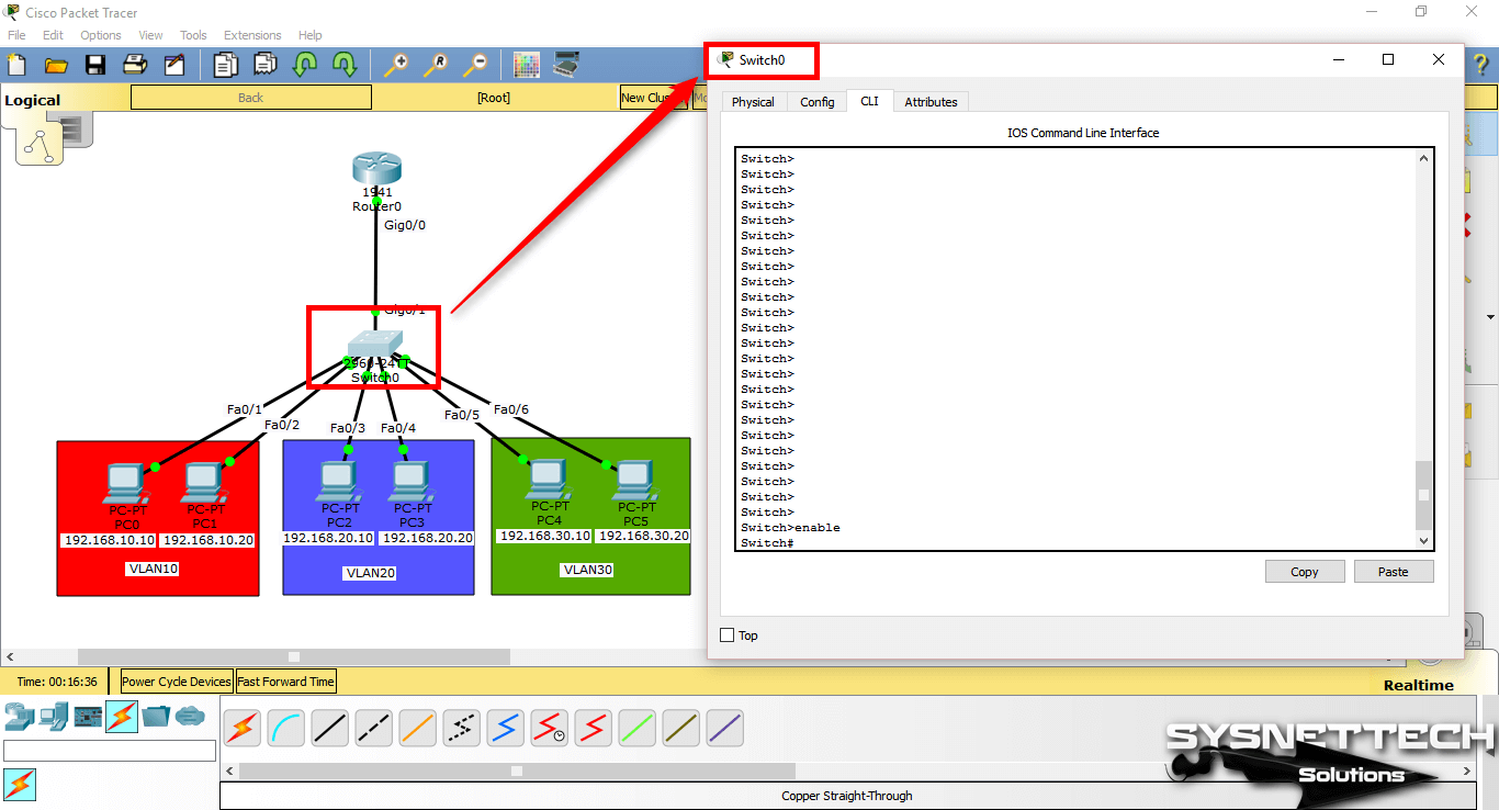
After configuring the Cisco Router’s interface and the TCP/IP settings of the computers, click Switch and click the CLI tab in the window that opens. To change to Privileged mode, execute enable.
Step 3
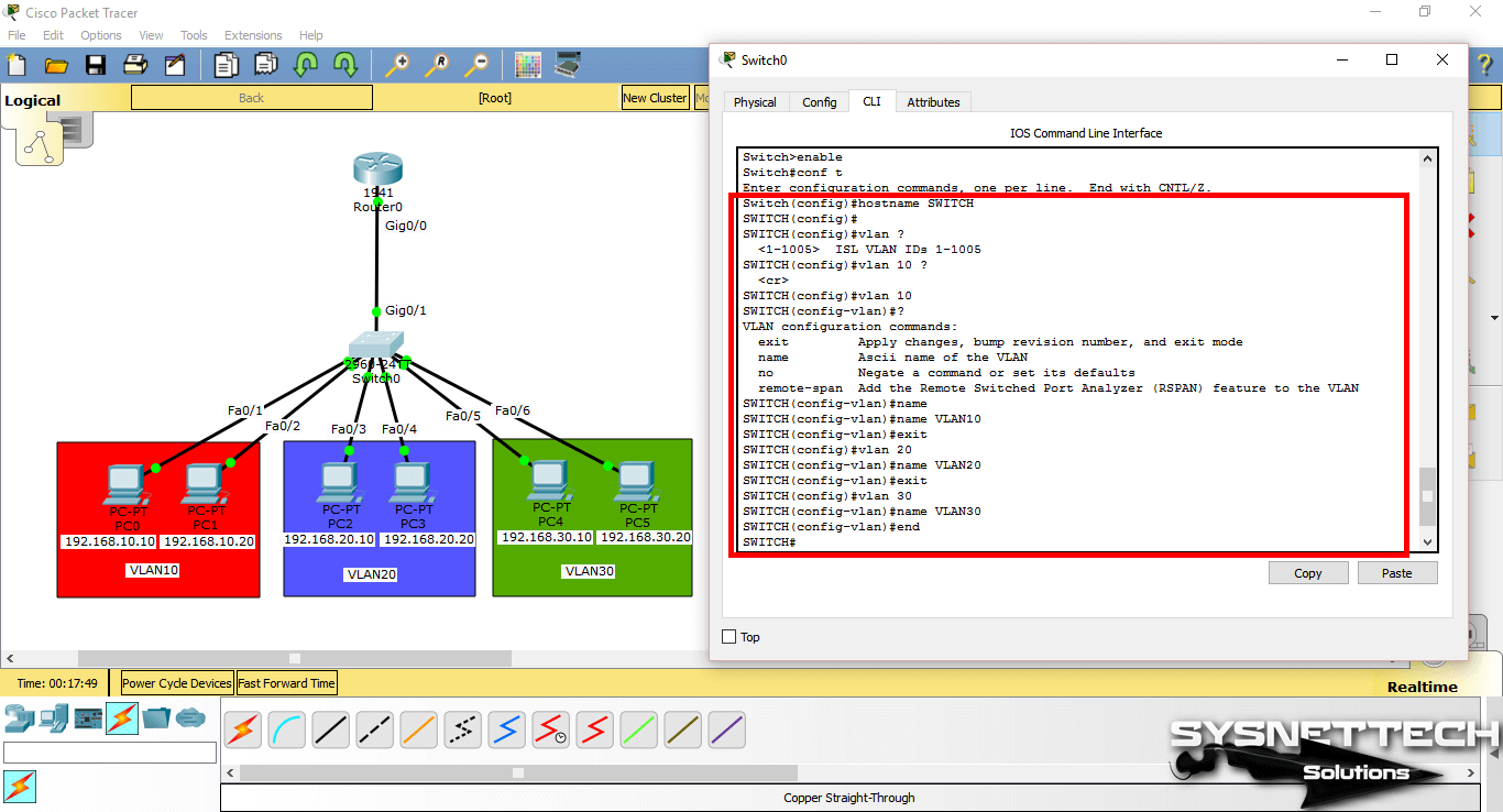
After making the basic settings, create 3 different VLAN groups according to the topology you have created on the Switch. Use the following commands to create a VLAN by topology.
Switch# conf t
Switch(config)# hostname SWITCH
SWITCH(config)# vlan 10
SWITCH(config-vlan)# name VLAN10
SWITCH(config-vlan)# exit
SWITCH(config)# vlan 20
SWITCH(config-vlan)# name VLAN20
SWITCH(config-vlan)# exit
SWITCH(config)# vlan 30
SWITCH(config-vlan)# name VLAN30
SWITCH(config-vlan)# exit
Step 4
After creating VLANs for departments, you need to make clients connected to the Switch interface to VLANs.
Switch from privileged configuration mode on Cisco Switch to global configuration mode.
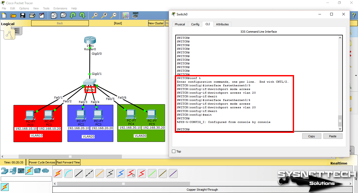
To assign clients in the red zone to VLAN10, perform the following commands in order.
SWITCH# conf t
SWITCH(config)# interface fastethernet 0/1
SWITCH(config-if)# switchport mode access
SWITCH(config-if)# switchport access vlan 10
SWITCH(config-if)# exit
SWITCH(config)# interface fastethernet 0/2
SWITCH(config-if)# switchport mode access
SWITCH(config-if)# switchport access vlan 10
SWITCH(config-if)# exit
SWITCH(config)# end
Step 5
To assign clients in the blue zone to VLAN20, perform the following commands in order.
SWITCH# conf t
SWITCH(config)# interface fastethernet 0/3
SWITCH(config-if)# switchport mode access
SWITCH(config-if)# switchport access vlan 20
SWITCH(config-if)# exit
SWITCH(config)# interface fastethernet 0/4
SWITCH(config-if)# switchport mode access
SWITCH(config-if)# switchport access vlan 20
SWITCH(config-if)# exit
SWITCH(config)# end
Step 6
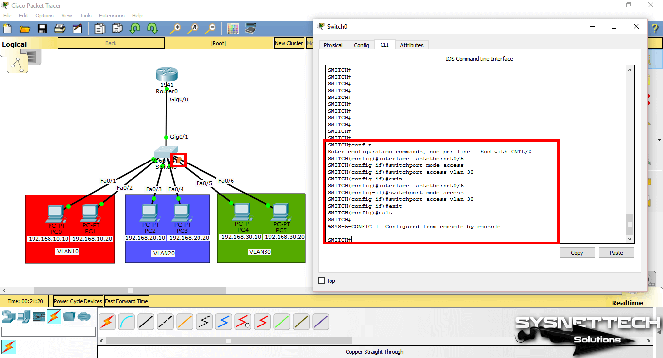
To assign clients in the green zone to the VLAN20, perform the following commands in order.
SWITCH# conf t
SWITCH(config)# interface fastethernet 0/5
SWITCH(config-if)# switchport mode access
SWITCH(config-if)# switchport access vlan 30
SWITCH(config-if)# exit
SWITCH(config)# interface fastethernet 0/6
SWITCH(config-if)# switchport mode access
SWITCH(config-if)# switchport access vlan 30
SWITCH(config-if)# exit
SWITCH(config)# end
Step 7
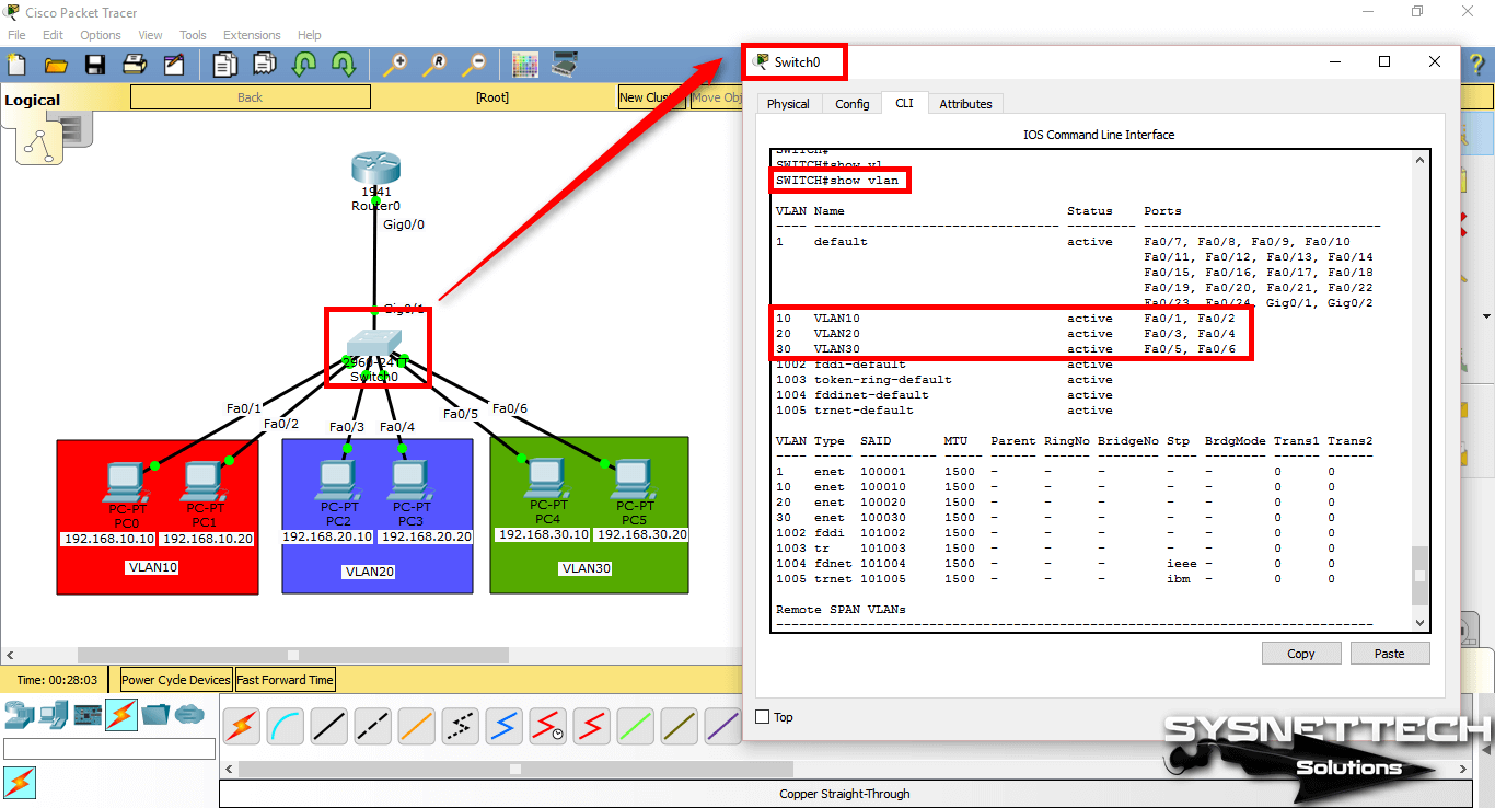
After adding the Switchport to the VLANs, check the interfaces you have created and made on the Switch with the show vlan command.
Step 8
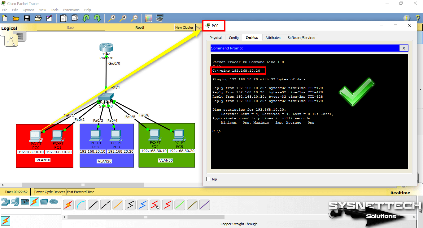
Since the network ports of PC0 and PC1 are connected to the VLAN10, you will see that there is a connection when you ping between these computers.
Step 9
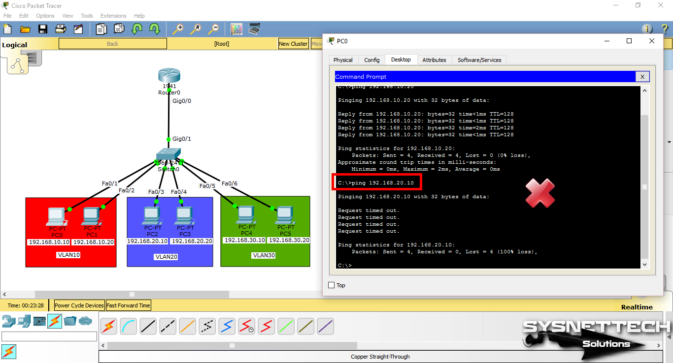
When you ping between computers with other VLANs, you will see that the operation failed.
A ping test from PC0 to PC2 which is a member of VLAN20;
Step 10
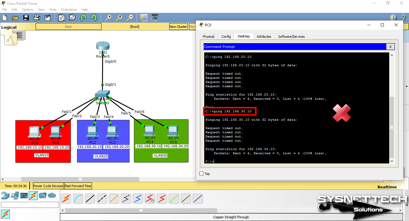
When you ping PC4 from PC0 to VLAN30 member, ping will fail. The reason ping failed is that no routing has been made between the VLANs.
NOTE: When you configure VLANs on the Layer 2 switch, if there is a Router in the environment, you need to configure the Inter-VLAN.
Assigning a Management IP Address to VLANs
By granting a management IP address to VLANs, you can control your devices from the local or remote network.
The ip address command is used in the configuration mode of the port to assign an IP address to the interface of a router. In the Switch, this operation is performed in the settings of the VLAN you will assign IP.
A management IP can be assigned for each VLAN created.
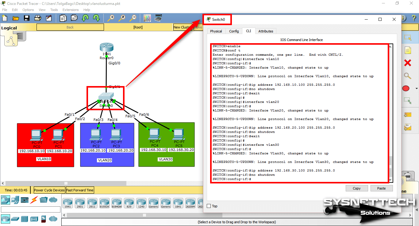
To add management addresses for VLAN10, VLAN20, and VLAN30, addressing the network topology, follow these steps:
Step 1
In CLI, execute the configure terminal command and then the interface command (name of the vlan) to configure the corresponding VLAN.
SWITCH#conf t
Enter configuration commands, one per line. End with CNTL/Z.
SWITCH(config)#interface vlan 10
SWITCH(config-if)#
%LINK-5-CHANGED: Interface Vlan10, changed state to up
%LINEPROTO-5-UPDOWN: Line protocol on Interface Vlan10, changed state to up
SWITCH(config-if)#ip address 192.168.10.100 255.255.255.0
SWITCH(config-if)#no shutdown
SWITCH(config-if)#exit
SWITCH(config)#
SWITCH(config)#interface vlan 20
SWITCH(config-if)#
%LINK-5-CHANGED: Interface Vlan20, changed state to up
%LINEPROTO-5-UPDOWN: Line protocol on Interface Vlan20, changed state to up
SWITCH(config-if)#ip address 192.168.20.100 255.255.255.0
SWITCH(config-if)#no shutdown
SWITCH(config-if)#exit
SWITCH(config)#
SWITCH(config)#interface vlan 30
SWITCH(config-if)#
%LINK-5-CHANGED: Interface Vlan30, changed state to up
%LINEPROTO-5-UPDOWN: Line protocol on Interface Vlan30, changed state to up
SWITCH(config-if)#ip address 192.168.30.100 255.255.255.0
SWITCH(config-if)#no shutdown
SWITCH(config-if)#end
SWITCH#
Step 2
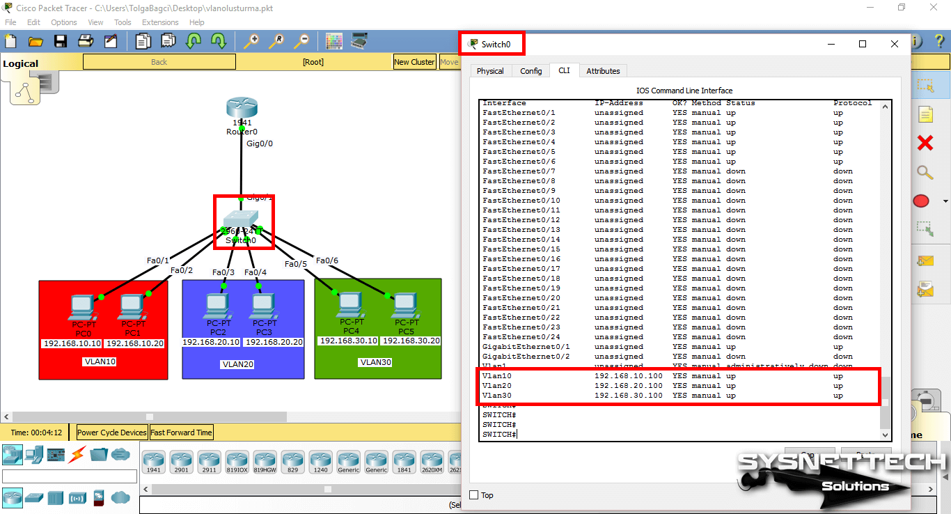
You can examine the IP addresses and port states of the interfaces with the show ip interface brief command in the switch.
Step 3
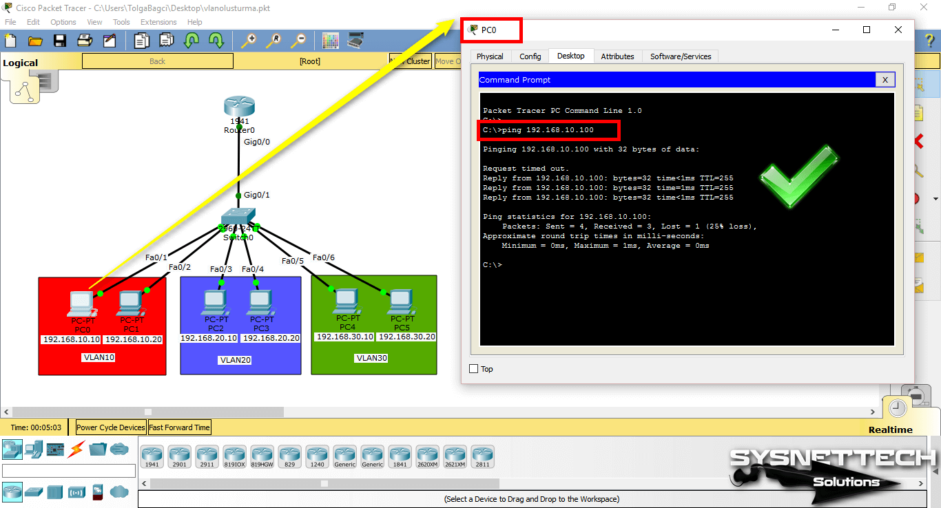
Pinging from PC0 to VLAN 10 management IP address (192.168.10.100) will be successful as follows.
Step 4
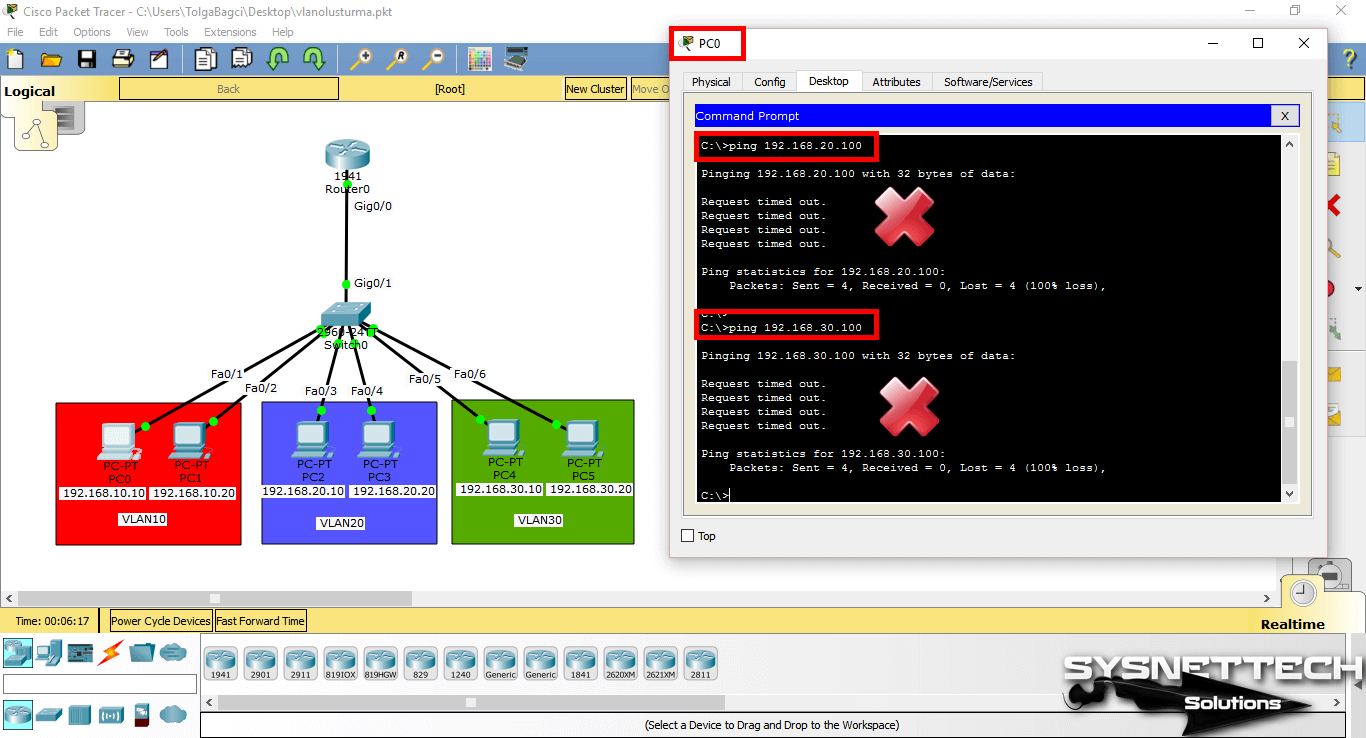
When you ping the VLAN 20 and VLAN 30 IP addresses (192.168.20.100 and 192.168.30.100) from PC0, the operation will fail.
Step 5
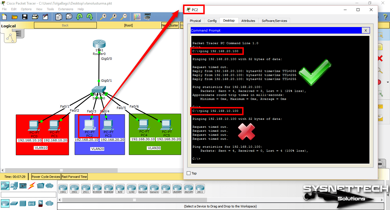
Finally, when you ping the management address from PC2, which is a member of VLAN20, the ping will succeed because clients that are members of the same VLAN can communicate.
If you ping the management address of the other VLAN, the operation will still fail.
Show Commands
SWITCH#show vlan

VLAN Name Status Ports
---- -------------------------------- --------- -------------------------------
1 default active Fa0/7, Fa0/8, Fa0/9, Fa0/10
Fa0/11, Fa0/12, Fa0/13, Fa0/14
Fa0/15, Fa0/16, Fa0/17, Fa0/18
Fa0/19, Fa0/20, Fa0/21, Fa0/22
Fa0/23, Fa0/24, Gig0/1, Gig0/2
10 VLAN10 active Fa0/1, Fa0/2
20 VLAN20 active Fa0/3, Fa0/4
30 VLAN30 active Fa0/5, Fa0/6
1002 fddi-default active
1003 token-ring-default active
1004 fddinet-default active
1005 trnet-default active

VLAN Type SAID MTU Parent RingNo BridgeNo Stp BrdgMode Trans1 Trans2
---- ----- ---------- ----- ------ ------ -------- ---- -------- ------ ------
1 enet 100001 1500 - - - - - 0 0
10 enet 100010 1500 - - - - - 0 0
20 enet 100020 1500 - - - - - 0 0
30 enet 100030 1500 - - - - - 0 0
1002 fddi 101002 1500 - - - - - 0 0
1003 tr 101003 1500 - - - - - 0 0
1004 fdnet 101004 1500 - - - ieee - 0 0
1005 trnet 101005 1500 - - - ibm - 0 0

Remote SPAN VLANs
------------------------------------------------------------------------------

Primary Secondary Type Ports
------- --------- ----------------- ------------------------------------------
SWITCH#
SWITCH#show vlan brief

VLAN Name Status Ports
---- -------------------------------- --------- -------------------------------
1 default active Fa0/7, Fa0/8, Fa0/9, Fa0/10
Fa0/11, Fa0/12, Fa0/13, Fa0/14
Fa0/15, Fa0/16, Fa0/17, Fa0/18
Fa0/19, Fa0/20, Fa0/21, Fa0/22
Fa0/23, Fa0/24, Gig0/1, Gig0/2
10 VLAN10 active Fa0/1, Fa0/2
20 VLAN20 active Fa0/3, Fa0/4
30 VLAN30 active Fa0/5, Fa0/6
1002 fddi-default active
1003 token-ring-default active
1004 fddinet-default active
1005 trnet-default active
SWITCH#
SWITCH#show running-config
Building configuration...

Current configuration : 1351 bytes
!
version 12.2
no service timestamps log datetime msec
no service timestamps debug datetime msec
no service password-encryption
!
hostname SWITCH
!
!
spanning-tree mode pvst
!
interface FastEthernet0/1
switchport access vlan 10
switchport mode access
!
interface FastEthernet0/2
switchport access vlan 10
switchport mode access
!
interface FastEthernet0/3
switchport access vlan 20
switchport mode access
!
interface FastEthernet0/4
switchport access vlan 20
switchport mode access
!
interface FastEthernet0/5
switchport access vlan 30
switchport mode access
!
interface FastEthernet0/6
switchport access vlan 30
switchport mode access
!
interface FastEthernet0/7
!
interface FastEthernet0/8
!
interface FastEthernet0/9
!
interface FastEthernet0/10
!
interface FastEthernet0/11
!
interface FastEthernet0/12
!
interface FastEthernet0/13
!
interface FastEthernet0/14
!
interface FastEthernet0/15
!
interface FastEthernet0/16
!
interface FastEthernet0/17
!
interface FastEthernet0/18
!
interface FastEthernet0/19
!
interface FastEthernet0/20
!
interface FastEthernet0/21
!
interface FastEthernet0/22
!
interface FastEthernet0/23
!
interface FastEthernet0/24
!
interface GigabitEthernet0/1
!
interface GigabitEthernet0/2
!
interface Vlan1
no ip address
shutdown
!
line con 0
!
line vty 0 4
login
line vty 5 15
login
!
end
SWITCH#
SWITCH#show ip interface brief
Interface IP-Address OK? Method Status Protocol
FastEthernet0/1 unassigned YES manual up up
FastEthernet0/2 unassigned YES manual up up
FastEthernet0/3 unassigned YES manual up up
FastEthernet0/4 unassigned YES manual up up
FastEthernet0/5 unassigned YES manual up up
FastEthernet0/6 unassigned YES manual up up
FastEthernet0/7 unassigned YES manual down down
FastEthernet0/8 unassigned YES manual down down
FastEthernet0/9 unassigned YES manual down down
FastEthernet0/10 unassigned YES manual down down
FastEthernet0/11 unassigned YES manual down down
FastEthernet0/12 unassigned YES manual down down
FastEthernet0/13 unassigned YES manual down down
FastEthernet0/14 unassigned YES manual down down
FastEthernet0/15 unassigned YES manual down down
FastEthernet0/16 unassigned YES manual down down
FastEthernet0/17 unassigned YES manual down down
FastEthernet0/18 unassigned YES manual down down
FastEthernet0/19 unassigned YES manual down down
FastEthernet0/20 unassigned YES manual down down
FastEthernet0/21 unassigned YES manual down down
FastEthernet0/22 unassigned YES manual down down
FastEthernet0/23 unassigned YES manual down down
FastEthernet0/24 unassigned YES manual down down
GigabitEthernet0/1 unassigned YES manual up up
GigabitEthernet0/2 unassigned YES manual down down
Vlan1 unassigned YES manual administratively down down
Vlan10 192.168.10.100 YES manual up up
Vlan20 192.168.20.100 YES manual up up
Vlan30 192.168.30.100 YES manual up up
Video
You can watch the video below to create virtual LANs on Packet Tracer and also subscribe to our YouTube channel to support us!
Final Word
In this article, we have examined how to create VLANs in a Cisco Switch with the simulator program, and assign an IP address to the VLAN. If you want to enable data communication between VLANs, you must activate the Inter-VLAN. Thanks for following us!
Related Articles
♦ Create a Network
♦ VLAN Routing
♦ SSH
♦ Telnet
♦ DHCP Relay Agent


