Configuring Routing Between VLANs
This module provides an overview of VLANs. It describes the encapsulation protocols used for routing between VLANs and provides
some basic information about designing VLANs. This module contains tasks for configuring routing between VLANS.
Information About Routing Between VLANs
Virtual Local Area Network Definition
A virtual local area network (VLAN) is a switched network that is logically segmented on an organizational basis, by functions,
project teams, or applications rather than on a physical or geographical basis. For example, all workstations and servers
used by a particular workgroup team can be connected to the same VLAN, regardless of their physical connections to the network
or the fact that they might be intermingled with other teams. Reconfiguration of the network can be done through software
rather than by physically unplugging and moving devices or wires.
A VLAN can be thought of as a broadcast domain that exists within a defined set of switches. A VLAN consists of a number
of end systems, either hosts or network equipment (such as bridges and routers), connected by a single bridging domain. The
bridging domain is supported on various pieces of network equipment; for example, LAN switches that operate bridging protocols
between them with a separate bridge group for each VLAN.
VLANs are created to provide the segmentation services traditionally provided by routers in LAN configurations. VLANs address
scalability, security, and network management. Routers in VLAN topologies provide broadcast filtering, security, address summarization,
and traffic flow management. None of the switches within the defined group will bridge any frames, not even broadcast frames,
between two VLANs. Several key issues described in the following sections need to be considered when designing and building
switched LAN internetworks:
LAN Segmentation
VLANs allow logical network topologies to overlay the physical switched
infrastructure such that any arbitrary collection of LAN ports can be combined
into an autonomous user group or community of interest. The technology
logically segments the network into separate Layer 2 broadcast domains whereby
packets are switched between ports designated to be within the same VLAN. By
containing traffic originating on a particular LAN only to other LANs in the
same VLAN, switched virtual networks avoid wasting bandwidth, a drawback
inherent to traditional bridged and switched networks in which packets are
often forwarded to LANs with no need for them. Implementation of VLANs also
improves scalability, particularly in LAN environments that support broadcast-
or multicast-intensive protocols and applications that flood packets throughout
the network.
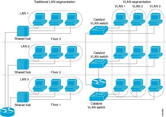
The figure below illustrates the difference between traditional
physical LAN segmentation and logical VLAN segmentation.
Security
VLANs improve security by isolating groups. High-security users can be grouped into a VLAN, possibly on the same physical
segment, and no users outside that VLAN can communicate with them.
Broadcast Control
Just as switches isolate collision domains for attached hosts and only forward appropriate traffic out a particular port,
VLANs provide complete isolation between VLANs. A VLAN is a bridging domain, and all broadcast and multicast traffic is contained
within it.
VLAN Performance
The logical grouping of users allows an accounting group to make intensive use of a networked accounting system assigned to
a VLAN that contains just that accounting group and its servers. That group’s work will not affect other users. The VLAN configuration
improves general network performance by not slowing down other users sharing the network.
Network Management
The logical grouping of users allows easier network management. It is not necessary to pull cables to move a user from one
network to another. Adds, moves, and changes are achieved by configuring a port into the appropriate VLAN.
Network Monitoring Using SNMP
SNMP support has been added to provide mib-2 interfaces sparse table support for Fast Ethernet subinterfaces. Monitor your
VLAN subinterface using the
show
vlans EXEC command. For more information on configuring SNMP on your Cisco network device or enabling an SNMP agent for remote
access, see the “Configuring SNMP Support” module in the
Cisco IOS Network Management Configuration Guide .
Communication Between VLANs
Communication between VLANs is accomplished through routing, and the traditional security and filtering functions of the router
can be used. Cisco IOS software provides network services such as security filtering, quality of service (QoS), and accounting
on a per-VLAN basis. As switched networks evolve to distributed VLANs, Cisco IOS software provides key inter-VLAN communications
and allows the network to scale.
Before Cisco IOS Release 12.2, Cisco IOS support for interfaces that have 802.1Q encapsulation configured is IP, IP multicast,
and IPX routing between respective VLANs represented as subinterfaces on a link. New functionality has been added in IEEE
802.1Q support for bridging on those interfaces and the capability to configure and use integrated routing and bridging (IRB).
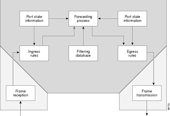
Relaying Function
The relaying function level, as displayed in the figure below, is the
lowest level in the architectural model described in the IEEE 802.1Q standard
and presents three types of rules:
-
Ingress rules—Rules
relevant to the classification of received frames belonging to a VLAN. -
Forwarding rules between
ports—Rules decide whether to filter or forward the frame. -
Egress rules (output of
frames from the switch)—Rules decide if the frame must be sent tagged or
untagged.
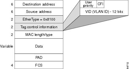
The Tagging Scheme
The figure below shows the tagging scheme proposed by the 802.3ac
standard, that is, the addition of the four octets after the source MAC
address. Their presence is indicated by a particular value of the EtherType
field (called TPID), which has been fixed to be equal to 0x8100. When a frame
has the EtherType equal to 0x8100, this frame carries the tag IEEE
802.1Q/802.1p. The tag is stored in the following two octets and it contains 3
bits of user priority, 1 bit of Canonical Format Identifier (CFI), and 12 bits
of VLAN ID (VID). The 3 bits of user priority are used by the 802.1p standard;
the CFI is used for compatibility reasons between Ethernet-type networks and
Token Ring-type networks. The VID is the identification of the VLAN, which is
basically used by the 802.1Q standard; being on 12 bits, it allows the
identification of 4096 VLANs.
After the two octets of TPID and the two octets of the Tag Control
Information field there are two octets that originally would have been located
after the Source Address field where there is the TPID. They contain either the
MAC length in the case of IEEE 802.3 or the EtherType in the case of Ethernet
version 2.
The EtherType and VLAN ID are inserted after the MAC source address,
but before the original Ethertype/Length or Logical Link Control (LLC). The
1-bit CFI included a T-R Encapsulation bit so that Token Ring frames can be
carried across Ethernet backbones without using 802.1H translation.
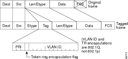
Frame Control Sequence Recomputation
The figure below shows how adding a tag in a frame recomputes the Frame
Control Sequence. 802.1p and 802.1Q share the same tag.
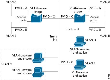
Native VLAN
Each physical port has a parameter called PVID. Every 802.1Q port is
assigned a PVID value that is of its native VLAN ID (default is VLAN 1). All
untagged frames are assigned to the LAN specified in the PVID parameter. When a
tagged frame is received by a port, the tag is respected. If the frame is
untagged, the value contained in the PVID is considered as a tag. Because the
frame is untagged and the PVID is tagged to allow the coexistence, as shown in
the figure below, on the same pieces of cable of VLAN-aware bridge/stations and
of VLAN-unaware bridges/stations. Consider, for example, the two stations
connected to the central trunk link in the lower part of the figure below. They
are VLAN-unaware and they will be associated to the VLAN C, because the PVIDs
of the VLAN-aware bridges are equal to VLAN C. Because the VLAN-unaware
stations will send only untagged frames, when the VLAN-aware bridge devices
receive these untagged frames they will assign them to VLAN C.
PVST+
PVST+ provides support for 802.1Q trunks and the mapping of multiple spanning trees to the single spanning tree of 802.1Q
switches.
The PVST+ architecture distinguishes three types of regions:
-
A PVST region
-
A PVST+ region
-
A MST region
Each region consists of a homogenous type of switch. A PVST region can be connected to a PVST+ region by connecting two ISL
ports. Similarly, a PVST+ region can be connected to an MST region by connecting two 802.1Q ports.
At the boundary between a PVST region and a PVST+ region the mapping of spanning trees is one-to-one. At the boundary between
a MST region and a PVST+ region, the ST in the MST region maps to one PVST in the PVST+ region. The one it maps to is called
the common spanning tree (CST). The default CST is the PVST of VLAN 1 (Native VLAN).
All PVSTs, except for the CST, are tunneled through the MST region. Tunneling means that bridge protocol data units (BPDUs)
are flooded through the MST region along the single spanning tree present in the MST region.
Ingress and Egress Rules
The BPDU transmission on the 802.1Q port of a PVST+ router will be implemented in compliance with the following rules:
-
The CST BPDU (of VLAN 1, by default) is sent to the IEEE address.
-
All the other BPDUs are sent to Shared Spanning Tree Protocol (SSTP)-Address and encapsulated with Logical Link Control-Subnetwork
Access Protocol (LLC-SNAP) header. -
The BPDU of the CST and BPDU of the VLAN equal to the PVID of the 802.1Q trunk are sent untagged.
-
All other BPDUs are sent tagged with the VLAN ID.
-
The CST BPDU is also sent to the SSTP address.
-
Each SSTP-addressed BPDU is also tailed by a Tag-Length-Value for the PVID checking.
The BPDU reception on the 802.1Q port of a PVST+ router will follow these rules:
-
All untagged IEEE addressed BPDUs must be received on the PVID of the 802.1Q port.
-
The IEEE addressed BPDUs whose VLAN ID matches the Native VLAN are processed by CST.
-
All the other IEEE addressed BPDUs whose VLAN ID does not match the Native VLAN and whose port type is not of 802.1Q are processed
by the spanning tree of that particular VLAN ID. -
The SSTP addressed BPDU whose VLAN ID is not equal to the TLV are dropped and the ports are blocked for inconsistency.
-
All the other SSTP addressed BPDUs whose VLAN ID is not equal to the Native VLAN are processed by the spanning tree of that
particular VLAN ID. -
The SSTP addressed BPDUs whose VLAN ID is equal to the Native VLAN are dropped. It is used for consistency checking.
Integrated Routing and Bridging
IRB enables a user to route a given protocol between routed interfaces and bridge groups or route a given protocol between
the bridge groups. Integrated routing and bridging is supported on the following protocols:
-
IP
-
IPX
-
AppleTalk
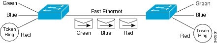
VLAN Colors
VLAN switching is accomplished through frame tagging
where traffic originating and contained within a particular virtual topology carries a unique VLAN ID as it traverses a common
backbone or trunk link. The VLAN ID enables VLAN switching devices to make intelligent forwarding decisions based on the embedded
VLAN ID. Each VLAN is differentiated by a color
, or VLAN identifier. The unique VLAN ID determines the frame coloring
for the VLAN. Packets originating and contained within a particular VLAN carry the identifier that uniquely defines that VLAN
(by the VLAN ID).
The VLAN ID allows VLAN switches and routers to selectively forward packets to ports with the same VLAN ID. The switch that
receives the frame from the source station inserts the VLAN ID and the packet is switched onto the shared backbone network.
When the frame exits the switched LAN, a switch strips the header and forwards the frame to interfaces that match the VLAN
color. If you are using a Cisco network management product such as VlanDirector, you can actually color code the VLANs and
monitor VLAN graphically.
Implementing VLANS
Network managers can logically group networks that span all major topologies, including high-speed technologies such as, ATM,
FDDI, and Fast Ethernet. By creating virtual LANs, system and network administrators can control traffic patterns and react
quickly to relocations and keep up with constant changes in the network due to moving requirements and node relocation just
by changing the VLAN member list in the router configuration. They can add, remove, or move devices or make other changes
to network configuration using software to make the changes.
Issues regarding creating VLANs should have been addressed when you developed your network design. Issues to consider include
the following:
-
Scalability
-
Performance improvements
-
Security
-
Network additions, moves, and changes
Communication Between VLANs
Cisco IOS software provides full-feature routing at Layer 3 and translation at Layer 2 between VLANs. Five different protocols
are available for routing between VLANs:
All five of these technologies are based on OSI Layer 2 bridge multiplexing mechanisms.
Inter-Switch Link Protocol
The Inter-Switch Link (ISL) protocol is used to interconnect two VLAN-capable Ethernet, Fast Ethernet, or Gigabit Ethernet
devices, such as the Catalyst 3000 or 5000 switches and Cisco 7500 routers. The ISL protocol is a packet-tagging protocol
that contains a standard Ethernet frame and the VLAN information associated with that frame. The packets on the ISL link contain
a standard Ethernet, FDDI, or Token Ring frame and the VLAN information associated with that frame. ISL is currently supported
only over Fast Ethernet links, but a single ISL link, or trunk, can carry different protocols from multiple VLANs.
Procedures for configuring ISL and Token Ring ISL (TRISL) features are provided in the Configuring Routing Between VLANs
with Inter-Switch Link Encapsulation section.
IEEE 802.10 Protocol
The IEEE 802.10 protocol provides connectivity between VLANs. Originally developed to address the growing need for security
within shared LAN/MAN environments, it incorporates authentication and encryption techniques to ensure data confidentiality
and integrity throughout the network. Additionally, by functioning at Layer 2, it is well suited to high-throughput, low-latency
switching environments. The IEEE 802.10 protocol can run over any LAN or HDLC serial interface.
Procedures for configuring routing between VLANs with IEEE 802.10 encapsulation are provided in the Configuring Routing Between
VLANs with IEEE 802.10 section.
IEEE 802.1Q Protocol
The IEEE 802.1Q protocol is used to interconnect multiple switches and routers, and for defining VLAN topologies. Cisco currently
supports IEEE 802.1Q for Fast Ethernet and Gigabit Ethernet interfaces.
 Note |
Cisco does not support IEEE 802.1Q encapsulation for Ethernet interfaces. |
Procedures for configuring routing between VLANs with IEEE 802.1Q encapsulation are provided in the Configuring Routing Between
VLANs with IEEE 802.1Q Encapsulation.
ATM LANE Protocol
The ATM LAN Emulation (LANE) protocol provides a way for legacy LAN users to take advantage of ATM benefits without requiring
modifications to end-station hardware or software. LANE emulates a broadcast environment like IEEE 802.3 Ethernet on top of
an ATM network that is a point-to-point environment.
LANE makes ATM function like a LAN. LANE allows standard LAN drivers like NDIS and ODI to be used. The virtual LAN is transparent
to applications. Applications can use normal LAN functions without the underlying complexities of the ATM implementation.
For example, a station can send broadcasts and multicasts, even though ATM is defined as a point-to-point technology and does
not support any-to-any services.
To accomplish this, special low-level software is implemented on an ATM client workstation, called the LAN Emulation Client
(LEC). The client software communicates with a central control point called a LAN Emulation Server (LES). A broadcast and
unknown server (BUS) acts as a central point to distribute broadcasts and multicasts. The LAN Emulation Configuration Server
(LECS) holds a database of LECs and the ELANs they belong to. The database is maintained by a network administrator.
These protocols are described in detail in the
Cisco Internetwork Design Guide .
ATM LANE Fast Simple Server Replication Protocol
To improve the ATM LANE Simple Server Replication Protocol (SSRP), Cisco introduced the ATM LANE Fast Simple Server Replication
Protocol (FSSRP). FSSRP differs from LANE SSRP in that all configured LANE servers of an ELAN are always active. FSSRP-enabled
LANE clients have virtual circuits (VCs) established to a maximum of four LANE servers and BUSs at one time. If a single LANE
server goes down, the LANE client quickly switches over to the next LANE server and BUS, resulting in no data or LE ARP table
entry loss and no extraneous signalling.
The FSSRP feature improves upon SSRP such that LANE server and BUS switchover for LANE clients is immediate. With SSRP, a
LANE server would go down, and depending on the network load, it may have taken considerable time for the LANE client to come
back up joined to the correct LANE server and BUS. In addition to going down with SSRP, the LANE client would do the following:
-
Clear out its data direct VCs
-
Clear out its LE ARP entries
-
Cause substantial signalling activity and data loss
FSSRP was designed to alleviate these problems with the LANE client. With FSSRP, each LANE client is simultaneously joined
to up to four LANE servers and BUSs. The concept of the master LANE server and BUS is maintained; the LANE client uses the
master LANE server when it needs LANE server BUS services. However, the difference between SSRP and FSSRP is that if and when
the master LANE server goes down, the LANE client is already connected to multiple backup LANE servers and BUSs. The LANE
client simply uses the next backup LANE server and BUS as the master LANE server and BUS.
VLAN Interoperability
Cisco IOS features bring added benefits to the VLAN technology. Enhancements to ISL, IEEE 802.10, and ATM LANE implementations
enable routing of all major protocols between VLANs. These enhancements allow users to create more robust networks incorporating
VLAN configurations by providing communications capabilities between VLANs.
Inter-VLAN Communications
The Cisco IOS supports full routing of several protocols over ISL and
ATM LANE VLANs. IP, Novell IPX, and AppleTalk routing are supported over IEEE
802.10 VLANs. Standard routing attributes such as network advertisements,
secondaries, and help addresses are applicable, and VLAN routing is fast
switched. The table below shows protocols supported for each VLAN encapsulation
format and corresponding Cisco IOS software releases in which support was
introduced.
|
Protocol |
ISL |
ATM LANE |
IEEE 802.10 |
|---|---|---|---|
|
IP |
Release 11.1 |
Release 10.3 |
Release 11.1 |
|
Novell IPX (default encapsulation) |
Release 11.1 |
Release 10.3 |
Release 11.1 |
|
Novell IPX (configurable encapsulation) |
Release 11.3 |
Release 10.3 |
Release 11.3 |
|
AppleTalk Phase II |
Release 11.3 |
Release 10.3 |
— |
|
DECnet |
Release 11.3 |
Release 11.0 |
— |
|
Banyan VINES |
Release 11.3 |
Release 11.2 |
— |
|
XNS |
Release 11.3 |
Release 11.2 |
— |
|
CLNS |
Release 12.1 |
— |
— |
|
IS-IS |
Release 12.1 |
— |
— |
VLAN Translation
VLAN translation refers to the ability of the Cisco IOS software to translate between different VLANs or between VLAN and
non-VLAN encapsulating interfaces at Layer 2. Translation is typically used for selective inter-VLAN switching of nonroutable
protocols and to extend a single VLAN topology across hybrid switching environments. It is also possible to bridge VLANs on
the main interface; the VLAN encapsulating header is preserved. Topology changes in one VLAN domain do not affect a different
VLAN.
Designing Switched VLANs
By the time you are ready to configure routing between VLANs, you will have already defined them through the switches in
your network. Issues related to network design and VLAN definition should be addressed during your network design. See the
Cisco Internetwork Design Guide and the appropriate switch documentation for information on these topics:
-
Sharing resources between VLANs
-
Load balancing
-
Redundant links
-
Addressing
-
Segmenting networks with VLANs—Segmenting the network into broadcast groups improves network security. Use router access
lists based on station addresses, application types, and protocol types. -
Routers and their role in switched networks—In switched networks, routers perform broadcast management, route processing,
and distribution, and provide communication between VLANs. Routers provide VLAN access to shared resources and connect to
other parts of the network that are either logically segmented with the more traditional subnet approach or require access
to remote sites across wide-area links.
Frame Tagging in ISL
ISL is a Cisco protocol for interconnecting multiple switches and
maintaining VLAN information as traffic goes between switches. ISL provides
VLAN capabilities while maintaining full wire speed performance on Fast
Ethernet links in full- or half-duplex mode. ISL operates in a point-to-point
environment and will support up to 1000 VLANs. You can define virtually as many
logical networks as are necessary for your environment.
With ISL, an Ethernet frame is encapsulated with a header that
transports VLAN IDs between switches and routers. A 26-byte header that
contains a 10-bit VLAN ID is propounded to the Ethernet frame.
A VLAN ID is added to the frame only when the frame is prepended for a
nonlocal network. The figure below shows VLAN packets traversing the shared
backbone. Each VLAN packet carries the VLAN ID within the packet header.
You can configure routing between any number of VLANs in your network.
This section documents the configuration tasks for each protocol supported with
ISL encapsulation. The basic process is the same, regardless of the protocol
being routed. It involves the following tasks:
-
Enabling the protocol on
the router -
Enabling the protocol on
the interface -
Defining the encapsulation
format as ISL or TRISL -
Customizing the protocol
according to the requirements for your environment
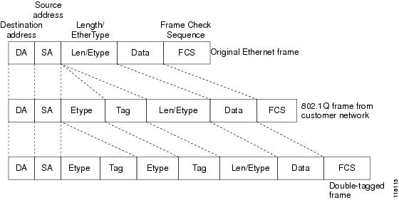
IEEE 802.1Q-in-Q VLAN Tag
Termination on Subinterfaces
IEEE 802.1Q-in-Q VLAN
Tag Termination simply adds another layer of IEEE 802.1Q tag (called “metro
tag” or “PE-VLAN”) to the 802.1Q tagged packets that enter the network. The
purpose is to expand the VLAN space by tagging the tagged packets, thus
producing a “double-tagged” frame. The expanded VLAN space allows the service
provider to provide certain services, such as Internet access on specific VLANs
for specific customers, and yet still allows the service provider to provide
other types of services for their other customers on other VLANs.
Generally the service
provider’s customers require a range of VLANs to handle multiple applications.
Service providers can allow their customers to use this feature to safely
assign their own VLAN IDs on subinterfaces because these subinterface VLAN IDs
are encapsulated within a service-provider designated VLAN ID for that
customer. Therefore there is no overlap of VLAN IDs among customers, nor does
traffic from different customers become mixed. The double-tagged frame is
“terminated” or assigned on a subinterface with an expanded
encapsulation
dot1q command that specifies the two VLAN ID tags
(outer VLAN ID and inner VLAN ID) terminated on the subinterface. See the
figure below.
IEEE 802.1Q-in-Q VLAN
Tag Termination is generally supported on whichever Cisco IOS features or
protocols are supported on the subinterface; the exception is that Cisco 10000
series Internet router only supports PPPoE. For example if you can run PPPoE on
the subinterface, you can configure a double-tagged frame for PPPoE. The only
restriction is whether you assign ambiguous or unambiguous subinterfaces for
the inner VLAN ID. See the figure below.
Note |
The Cisco 10000 |
The primary benefit
for the service provider is reduced number of VLANs supported for the same
number of customers. Other benefits of this feature include:
-
PPPoE
scalability. By expanding the available VLAN space from 4096 to approximately
16.8 million (4096 times 4096), the number of PPPoE sessions that can be
terminated on a given interface is multiplied. -
When deploying
Gigabyte Ethernet DSL Access Multiplexer (DSLAM) in wholesale model, you can
assign the inner VLAN ID to represent the end-customer virtual circuit (VC) and
assign the outer VLAN ID to represent the service provider ID.
The Q-in-Q VLAN tag
termination feature is simpler than the IEEE 802.1Q tunneling feature deployed
for the Catalyst 6500 series switches or the Catalyst 3550 and Catalyst 3750
switches. Whereas switches require IEEE 802.1Q tunnels on interfaces to carry
double-tagged traffic, routers need only encapsulate Q-in-Q VLAN tags within
another level of 802.1Q tags in order for the packets to arrive at the correct
destination as shown in figure below.
Double-Tagged Ethernet Frames
Cisco 10000 Series Internet
Router Application
For the emerging
broadband Ethernet-based DSLAM market, the Cisco 10000 series Internet router
supports Q-in-Q encapsulation. With the Ethernet-based DSLAM model shown in the
figure below, customers typically get their own VLAN and all these VLANs are
aggregated on a DSLAM.
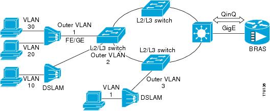
VLAN aggregation on a
DSLAM will result in a lot of aggregate VLANs that at some point need to be
terminated on the broadband remote access servers (BRAS). Although the model
could connect the DSLAMs directly to the BRAS, a more common model uses the
existing Ethernet-switched network where each DSLAM VLAN ID is tagged with a
second tag (Q-in-Q) as it connects into the Ethernet-switched network.
The only model that
is supported is PPPoE over Q-in-Q (PPPoEoQinQ). This can either be a PPP
terminated session or as a L2TP LAC session.
The Cisco 10000
series Internet router already supports plain PPPoE and PPP over 802.1Q
encapsulation. Supporting PPP over Q-in-Q encapsulation is new. PPP over Q-in-Q
encapsulation processing is an extension to 802.1q encapsulation processing. A
Q-in-Q frame looks like a VLAN 802.1Q frame, only it has two 802.1Q tags
instead of one.
PPP over Q-in-Q
encapsulation supports configurable outer tag Ethertype. The configurable
Ethertype field values are 0x8100 (default), 0x9100, and 0x9200. See the figure
below.
![]()
Security ACL Application on the Cisco 10000 Series Internet Router
The IEEE 802.1Q-in-Q VLAN Tag Termination feature provides limited security access control list (ACL) support for the Cisco
10000 series Internet router.
If you apply an ACL to PPPoE traffic on a Q-in-Q subinterface in a VLAN, apply the ACL directly on the PPPoE session, using
virtual access interfaces (VAIs) or RADIUS attribute 11 or 242.
You can apply ACLs to virtual access interfaces by configuring them under virtual template interfaces. You can also configure
ACLs by using RADIUS attribute 11 or 242. When you use attribute 242, a maximum of 30,000 sessions can have ACLs.
ACLs that are applied to the VLAN Q-in-Q subinterface have no effect and are silently ignored. In the following example, ACL
1 that is applied to the VLAN Q-in-Q subinterface level will be ignored:
Router(config)# interface FastEthernet3/0/0.100
Router(config-subif)# encapsulation dot1q 100 second-dot1q 200
Router(config-subif)# ip access-group 1
Unambiguous and Ambiguous Subinterfaces
The
encapsulation
dot1q command is used to configure Q-in-Q termination on a subinterface. The command accepts an Outer VLAN ID and one or more Inner
VLAN IDs. The outer VLAN ID always has a specific value, while inner VLAN ID can either be a specific value or a range of
values.
A subinterface that is configured with a single Inner VLAN ID is called an unambiguous Q-in-Q subinterface. In the following
example, Q-in-Q traffic with an Outer VLAN ID of 101 and an Inner VLAN ID of 1001 is mapped to the Gigabit Ethernet 1/0.100
subinterface:
Router(config)# interface gigabitEehernet1/0.100
Router(config-subif)# encapsulation dot1q 101 second-dot1q 1001
A subinterface that is configured with multiple Inner VLAN IDs is called an ambiguous Q-in-Q subinterface. By allowing multiple
Inner VLAN IDs to be grouped together, ambiguous Q-in-Q subinterfaces allow for a smaller configuration, improved memory usage
and better scalability.
In the following example, Q-in-Q traffic with an Outer VLAN ID of 101 and Inner VLAN IDs anywhere in the 2001-2100 and 3001-3100
range is mapped to the Gigabit Ethernet 1/0.101 subinterface.:
Router(config)# interface gigabitethernet1/0.101
Router(config-subif)# encapsulation dot1q 101 second-dot1q 2001-2100,3001-3100
Ambiguous subinterfaces can also use the
any keyword to specify the inner VLAN ID.
See the Monitoring and Maintaining VLAN Subinterfaces section for an example of how VLAN IDs are assigned to subinterfaces,
and for a detailed example of how the
any keyword is used on ambiguous subinterfaces.
Only PPPoE is supported on ambiguous subinterfaces. Standard IP routing is not supported on ambiguous subinterfaces.
Note |
On the Cisco 10000 series Internet router, Modular QoS services are only supported on unambiguous subinterfaces. |
How to Configure Routing Between VLANS
Configuring a VLAN Range
Using the VLAN Range feature, you can group VLAN subinterfaces together so that any command entered in a group applies to
every subinterface within the group. This capability simplifies configurations and reduces command parsing.
The VLAN Range feature provides the following benefits:
-
Simultaneous Configurations: Identical commands can be entered once for a range of subinterfaces, rather than being entered
separately for each subinterface. -
Overlapping Range Configurations: Overlapping ranges of subinterfaces can be configured.
-
Customized Subinterfaces: Individual subinterfaces within a range can be customized or deleted.
Restrictions
-
Each command you enter while you are in interface configuration mode with the interface range command is executed as it is entered. The commands are not batched together for execution after you exit interface configuration
mode. If you exit interface configuration mode while the commands are being executed, some commands might not be executed
on some interfaces in the range. Wait until the command prompt reappears before exiting interface configuration mode. -
The no interface range command is not supported. You must delete individual subinterfaces to delete a range.
Configuring a Range of VLAN Subinterfaces
Use the following commands to configure a range of VLAN subinterfaces.
SUMMARY STEPS
-
enable
-
configure
terminal
-
interface
range
{{ethernet | fastethernet | gigabitethernet | atm } slot / interface . subinterface — {{ethernet | fastethernet | gigabitethernet | atm }slot / interface . subinterface } -
encapsulation
dot1Q
vlan-id
-
no
shutdown
-
exit
-
show
running-config
-
show
interfaces
DETAILED STEPS
| Command or Action | Purpose | |||
|---|---|---|---|---|
| Step 1 |
Example: |
Enables privileged EXEC mode.
|
||
| Step 2 |
Example: |
Enters global configuration mode. |
||
| Step 3 |
Example: |
Selects the range of subinterfaces to be configured.
|
||
| Step 4 |
Example: |
Applies a unique VLAN ID to each subinterface within the range.
|
||
| Step 5 |
Example: |
Activates the interface.
|
||
| Step 6 |
Example: |
Returns to privileged EXEC mode. |
||
| Step 7 |
Example: |
Verifies subinterface configuration. |
||
| Step 8 |
Example: |
Verifies that subinterfaces have been created. |
Configuring Routing Between VLANs with Inter-Switch Link Encapsulation
This section describes the Inter-Switch Link (ISL) protocol and provides guidelines for configuring ISL and Token Ring ISL
(TRISL) features. This section contains the following:
Configuring AppleTalk Routing over ISL
AppleTalk can be routed over VLAN subinterfaces using the ISL and IEEE 802.10 VLAN encapsulation protocols. The AppleTalk
Routing over ISL and IEEE 802.10 Virtual LANs feature provides full-feature Cisco IOS software AppleTalk support on a per-VLAN
basis, allowing standard AppleTalk capabilities to be configured on VLANs.
To route AppleTalk over ISL or IEEE 802.10 between VLANs, you need to customize the subinterface to create the environment
in which it will be used. Perform the steps in the order in which they appear.
SUMMARY STEPS
-
enable
-
configure
terminal
-
appletalk
routing
[eigrp router-number ] -
interface
type
slot
/
port
.
subinterface-number -
encapsulation
isl
vlan-identifier
-
appletalk
cable-range
cable-range
[network . node ] -
appletalk
zone
zone-name
DETAILED STEPS
| Command or Action | Purpose | |
|---|---|---|
| Step 1 |
Example: |
Enables privileged EXEC mode.
|
| Step 2 |
Example: |
Enters global configuration mode. |
| Step 3 |
Example: |
Enables AppleTalk routing globally on either ISL or 802.10 interfaces. |
| Step 4 |
Example: |
Specifies the subinterface the VLAN will use. |
| Step 5 |
Example:Example:Example:Example: |
Defines the encapsulation format as either ISL (isl ) or IEEE 802.10 (sde ), and specifies the VLAN identifier or security association identifier, respectively. |
| Step 6 |
Example: |
Assigns the AppleTalk cable range and zone for the subinterface. |
| Step 7 |
Example: |
Assigns the AppleTalk zone for the subinterface. |
Configuring Banyan VINES Routing over ISL
Banyan VINES can be routed over VLAN subinterfaces using the ISL encapsulation protocol. The Banyan VINES Routing over ISL
Virtual LANs feature provides full-feature Cisco IOS software Banyan VINES support on a per-VLAN basis, allowing standard
Banyan VINES capabilities to be configured on VLANs.
To route Banyan VINES over ISL between VLANs, you need to configure ISL encapsulation on the subinterface. Perform the steps
in the following task in the order in which they appear:
SUMMARY STEPS
-
enable
-
configure
terminal
-
vines
routing
[address ] -
interface
type
slot
/
port
.
subinterface-number
-
encapsulation
isl
vlan-identifier
-
vines
metric
[whole [fraction ]]
DETAILED STEPS
| Command or Action | Purpose | |
|---|---|---|
| Step 1 |
Example: |
Enables privileged EXEC mode.
|
| Step 2 |
Example: |
Enters global configuration mode. |
| Step 3 |
Example: |
Enables Banyan VINES routing globally. |
| Step 4 |
Example: |
Specifies the subinterface on which ISL will be used. |
| Step 5 |
Example: |
Defines the encapsulation format as ISL (isl ), and specifies the VLAN identifier. |
| Step 6 |
Example: |
Enables VINES routing metric on an interface. |
Configuring DECnet Routing over ISL
DECnet can be routed over VLAN subinterfaces using the ISL VLAN encapsulation protocols. The DECnet Routing over ISL Virtual
LANs feature provides full-feature Cisco IOS software DECnet support on a per-VLAN basis, allowing standard DECnet capabilities
to be configured on VLANs.
To route DECnet over ISL VLANs, you need to configure ISL encapsulation on the subinterface. Perform the steps described in
the following task in the order in which they appear.
SUMMARY STEPS
-
enable
-
configure
terminal
- Router(config)# decnet [network —number ] routing [decnet-address ]
-
interface
type
slot
/
port
.
subinterface-number -
encapsulation
isl
vlan-identifier
-
decnet
cost
[cost-value ]
DETAILED STEPS
| Command or Action | Purpose | |
|---|---|---|
| Step 1 |
Example: |
Enables privileged EXEC mode.
|
| Step 2 |
Example: |
Enters global configuration mode. |
| Step 3 |
Router(config)# decnet [network —number ] routing [decnet-address ] Example: |
Enables DECnet on the router. |
| Step 4 |
Example: |
Specifies the subinterface on which ISL will be used. |
| Step 5 |
Example: |
Defines the encapsulation format as ISL (isl ), and specifies the VLAN identifier. |
| Step 6 |
Example: |
Enables DECnet cost metric on an interface. |
Configuring the Hot Standby Router Protocol over ISL
The Hot Standby Router Protocol (HSRP) provides fault tolerance and enhanced routing performance for IP networks. HSRP allows
Cisco IOS routers to monitor each other’s operational status and very quickly assume packet forwarding responsibility in the
event the current forwarding device in the HSRP group fails or is taken down for maintenance. The standby mechanism remains
transparent to the attached hosts and can be deployed on any LAN type. With multiple Hot Standby groups, routers can simultaneously
provide redundant backup and perform loadsharing across different IP subnets.
The figure below illustrates HSRP in use with ISL providing routing between several VLANs.
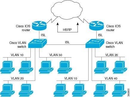
A separate HSRP group is configured for each VLAN subnet so that Cisco IOS router A can be the primary and forwarding router
for VLANs 10 and 20. At the same time, it acts as backup for VLANs 30 and 40. Conversely, Router B acts as the primary and
forwarding router for ISL VLANs 30 and 40, as well as the secondary and backup router for distributed VLAN subnets 10 and
20.
Running HSRP over ISL allows users to configure redundancy between multiple routers that are configured as front ends for
VLAN IP subnets. By configuring HSRP over ISLs, users can eliminate situations in which a single point of failure causes traffic
interruptions. This feature inherently provides some improvement in overall networking resilience by providing load balancing
and redundancy capabilities between subnets and VLANs.
To configure HSRP over ISLs between VLANs, you need to create the environment in which it will be used. Perform the tasks
described in the following sections in the order in which they appear.
SUMMARY STEPS
-
enable
-
configure
terminal
-
interface
type
slot
/
port
.
subinterface-number -
encapsulation
isl
vlan-identifier
-
ip
address
ip-address
mask
[secondary ] - Router(config-if)#
standby [group-number ]
ip [ip-address [secondary ]] -
standby
[group-number ]
timers
hellotime
holdtime -
standby
[group-number ]
priority
priority -
standby
[group-number ]
preempt -
standby
[group-number ]
track
type-number [interface-priority ] -
standby
[group-number ]
authentication
string
DETAILED STEPS
| Command or Action | Purpose | |
|---|---|---|
| Step 1 |
Example: |
Enables privileged EXEC mode.
|
| Step 2 |
Example: |
Enters global configuration mode. |
| Step 3 |
Example: |
Specifies the subinterface on which ISL will be used and enters interface configuration mode. |
| Step 4 |
Example: |
Defines the encapsulation format, and specifies the VLAN identifier. |
| Step 5 |
Example: |
Specifies the IP address for the subnet on which ISL will be used. |
| Step 6 |
Router(config-if)# Example: |
Enables HSRP. |
| Step 7 |
Example: |
Configures the time between hello packets and the hold time before other routers declare the active router to be down. |
| Step 8 |
Example: |
Sets the Hot Standby priority used to choose the active router. |
| Step 9 |
Example: |
Specifies that if the local router has priority over the current active router, the local router should attempt to take its |
| Step 10 |
Example: |
Configures the interface to track other interfaces, so that if one of the other interfaces goes down, the Hot Standby priority |
| Step 11 |
Example: |
Selects an authentication string to be carried in all HSRP messages. |
What to do next
Note |
For more information on HSRP, see the “Configuring HSRP” module in the |
Configuring IP Routing over TRISL
The IP routing over TRISL VLANs feature extends IP routing capabilities to include support for routing IP frame types in VLAN
configurations.
SUMMARY STEPS
-
enable
-
configure
terminal
-
ip
routing
-
interface
type
slot
/
port
.
subinterface-number
-
encapsulation
tr-isl
trbrf-vlan
vlanid
bridge-num
bridge-number -
ip
address
ip-address mask
DETAILED STEPS
| Command or Action | Purpose | |||
|---|---|---|---|---|
| Step 1 |
Example: |
Enables privileged EXEC mode.
|
||
| Step 2 |
Example: |
Enters global configuration mode. |
||
| Step 3 |
Example: |
Enables IP routing on the router. |
||
| Step 4 |
Example: |
Specifies the subinterface on which TRISL will be used and enters interface configuration mode. |
||
| Step 5 |
Example: |
Defines the encapsulation for TRISL.
|
||
| Step 6 |
Example: |
Sets a primary IP address for an interface.
|
Configuring IPX Routing on 802.10 VLANs over ISL
The IPX Encapsulation for 802.10 VLAN feature provides configurable IPX (Novell-FDDI, SAP, SNAP) encapsulation over 802.10
VLAN on router FDDI interfaces to connect the Catalyst 5000 VLAN switch. This feature extends Novell NetWare routing capabilities
to include support for routing all standard IPX encapsulations for Ethernet frame types in VLAN configurations. Users with
Novell NetWare environments can now configure any one of the three IPX Ethernet encapsulations to be routed using Secure Data
Exchange (SDE) encapsulation across VLAN boundaries. IPX encapsulation options now supported for VLAN traffic include the
following:
-
Novell-FDDI (IPX FDDI RAW to 802.10 on FDDI)
-
SAP (IEEE 802.2 SAP to 802.10 on FDDI)
-
SNAP (IEEE 802.2 SNAP to 802.10 on FDDI)
NetWare users can now configure consolidated VLAN routing over a single VLAN trunking FDDI interface. Not all IPX encapsulations
are currently supported for SDE VLAN. The IPX interior encapsulation support can be achieved by messaging the IPX header before
encapsulating in the SDE format. Fast switching will also support all IPX interior encapsulations on non-MCI platforms (for
example non-AGS+ and non-7000). With configurable Ethernet encapsulation protocols, users have the flexibility of using VLANs
regardless of their NetWare Ethernet encapsulation. Configuring Novell IPX encapsulations on a per-VLAN basis facilitates
migration between versions of Netware. NetWare traffic can now be routed across VLAN boundaries with standard encapsulation
options (arpa ,
sap , and
snap ) previously unavailable. Encapsulation types and corresponding framing types are described in the “Configuring Novell IPX
” module of the
Cisco IOS Novell IPX Configuration Guide .
Note |
Only one type of IPX encapsulation can be configured per VLAN (subinterface). The IPX encapsulation used must be the same |
To configure Cisco IOS software on a router with connected VLANs to exchange different IPX framing protocols, perform the
steps described in the following task in the order in which they are appear.
SUMMARY STEPS
-
enable
-
configure
terminal
-
ipx
routing
[node ] -
interface
fddi
slot
/
port
.
subinterface-number -
encapsulation
sde
vlan-identifier
-
ipx
network
network
encapsulation
encapsulation-type
DETAILED STEPS
| Command or Action | Purpose | |
|---|---|---|
| Step 1 |
Example: |
Enables privileged EXEC mode.
|
| Step 2 |
Example: |
Enters global configuration mode. |
| Step 3 |
Example: |
Enables IPX routing globally. |
| Step 4 |
Example: |
Specifies the subinterface on which SDE will be used and enters interface configuration mode. |
| Step 5 |
Example: |
Defines the encapsulation format and specifies the VLAN identifier. |
| Step 6 |
Example: |
Specifies the IPX encapsulation among Novell-FDDI, SAP, or SNAP. |
Configuring IPX Routing over TRISL
The IPX Routing over ISL VLANs feature extends Novell NetWare routing capabilities to include support for routing all standard
IPX encapsulations for Ethernet frame types in VLAN configurations. Users with Novell NetWare environments can configure either
SAP or SNAP encapsulations to be routed using the TRISL encapsulation across VLAN boundaries. The SAP (Novell Ethernet_802.2)
IPX encapsulation is supported for VLAN traffic.
NetWare users can now configure consolidated VLAN routing over a single VLAN trunking interface. With configurable Ethernet
encapsulation protocols, users have the flexibility of using VLANs regardless of their NetWare Ethernet encapsulation. Configuring
Novell IPX encapsulations on a per-VLAN basis facilitates migration between versions of Netware. NetWare traffic can now be
routed across VLAN boundaries with standard encapsulation options (sap and
snap ) previously unavailable. Encapsulation types and corresponding framing types are described in the “Configuring Novell IPX
” module of the
Cisco IOS Novell IPX Configuration Guide .
Note |
Only one type of IPX encapsulation can be configured per VLAN (subinterface). The IPX encapsulation used must be the same |
To configure Cisco IOS software to exchange different IPX framing protocols on a router with connected VLANs, perform the
steps in the following task in the order in which they are appear.
SUMMARY STEPS
-
enable
-
configure
terminal
-
ipx
routing
[node ] -
interface
type
slot
/
port
.
subinterface-number -
encapsulation
tr-isl
trbrf-vlan
trbrf-vlan
bridge-num
bridge-num -
ipx
network
network
encapsulation
encapsulation-type
DETAILED STEPS
| Command or Action | Purpose | |
|---|---|---|
| Step 1 |
Example: |
Enables privileged EXEC mode.
|
| Step 2 |
Example: |
Enters global configuration mode. |
| Step 3 |
Example: |
Enables IPX routing globally. |
| Step 4 |
Example: |
Specifies the subinterface on which TRISL will be used and enters interface configuration mode. |
| Step 5 |
Example: |
Defines the encapsulation for TRISL. |
| Step 6 |
Example: |
Specifies the IPX encapsulation on the subinterface by specifying the NetWare network number (if necessary) and the encapsulation |
What to do next
Note |
The default IPX encapsulation format for Cisco IOS routers is “novell-ether” (Novell Ethernet_802.3). If you are running |
Configuring VIP Distributed Switching over ISL
With the introduction of the VIP distributed ISL feature, ISL
encapsulated IP packets can be switched on Versatile Interface Processor (VIP)
controllers installed on Cisco 7500 series routers.
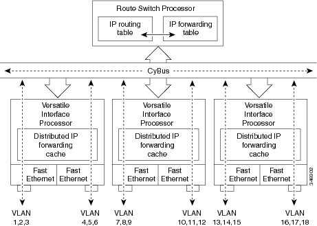
The second generation VIP2 provides distributed switching of IP
encapsulated in ISL in VLAN configurations. Where an aggregation route performs
inter-VLAN routing for multiple VLANs, traffic can be switched autonomously
on-card or between cards rather than through the central Route Switch Processor
(RSP). The figure below shows the VIP distributed architecture of the Cisco
7500 series router.
This distributed architecture allows incremental capacity increases
by installation of additional VIP cards. Using VIP cards for switching the
majority of IP VLAN traffic in multiprotocol environments substantially
increases routing performance for the other protocols because the RSP offloads
IP and can then be dedicated to switching the non-IP protocols.
VIP distributed switching offloads switching of ISL VLAN IP traffic
to the VIP card, removing involvement from the main CPU. Offloading ISL traffic
to the VIP card substantially improves networking performance. Because you can
install multiple VIP cards in a router, VLAN routing capacity is increased
linearly according to the number of VIP cards installed in the router.
To configure distributed switching on the VIP, you must first
configure the router for IP routing. Perform the tasks described below in the
order in which they appear.
SUMMARY STEPS
-
enable
-
configure
terminal
-
ip
routing
-
interface
type
slot
/
port-adapter
/
port
-
ip
route-cache
distributed
-
encapsulation
isl
vlan-identifier
DETAILED STEPS
| Command or Action | Purpose | |
|---|---|---|
| Step 1 |
Example: |
Enables privileged EXEC mode.
|
| Step 2 |
Example: |
Enters global configuration mode. |
| Step 3 |
Example: |
Enables IP routing on the router.
|
| Step 4 |
Example: |
Specifies the interface and enters interface configuration mode. |
| Step 5 |
Example: |
Enables VIP distributed switching of IP packets on the interface. |
| Step 6 |
Example: |
Defines the encapsulation format as ISL, and specifies the VLAN |
Configuring XNS Routing over ISL
XNS can be routed over VLAN subinterfaces using the ISL VLAN encapsulation protocol. The XNS Routing over ISL Virtual LANs
feature provides full-feature Cisco IOS software XNS support on a per-VLAN basis, allowing standard XNS capabilities to be
configured on VLANs.
To route XNS over ISL VLANs, you need to configure ISL encapsulation on the subinterface. Perform the steps described in the
following task in the order in which they appear.
SUMMARY STEPS
-
enable
-
configure
terminal
-
xns
routing
[address ] -
interface
type
slot
/
port
.
subinterface-number -
encapsulation
isl
vlan-identifier
-
xns
network
[number ]
DETAILED STEPS
| Command or Action | Purpose | |
|---|---|---|
| Step 1 |
Example: |
Enables privileged EXEC mode.
|
| Step 2 |
Example: |
Enters global configuration mode. |
| Step 3 |
Example: |
Enables XNS routing globally. |
| Step 4 |
Example: |
Specifies the subinterface on which ISL will be used and enters interface configuration mode. |
| Step 5 |
Example: |
Defines the encapsulation format as ISL (isl ), and specifies the VLAN identifier. |
| Step 6 |
Example: |
Enables XNS routing on the subinterface. |
Configuring CLNS Routing over ISL
CLNS can be routed over VLAN subinterfaces using the ISL VLAN encapsulation protocol. The CLNS Routing over ISL Virtual LANs
feature provides full-feature Cisco IOS software CLNS support on a per-VLAN basis, allowing standard CLNS capabilities to
be configured on VLANs.
To route CLNS over ISL VLANs, you need to configure ISL encapsulation on the subinterface. Perform the steps described in
the following task in the order in which they appear.
SUMMARY STEPS
-
enable
-
configure
terminal
-
clns
routing
-
interface
type
slot
/
port
.
subinterface-number -
encapsulation
isl
vlan-identifier
-
clns
enable
DETAILED STEPS
| Command or Action | Purpose | |
|---|---|---|
| Step 1 |
Example: |
Enables privileged EXEC mode.
|
| Step 2 |
Example: |
Enters global configuration mode. |
| Step 3 |
Example: |
Enables CLNS routing globally. |
| Step 4 |
Example: |
Specifies the subinterface on which ISL will be used and enters interface configuration mode. |
| Step 5 |
Example: |
Defines the encapsulation format as ISL (isl ), and specifies the VLAN identifier. |
| Step 6 |
Example: |
Enables CLNS routing on the subinterface. |
Configuring IS-IS Routing over ISL
IS-IS routing can be enabled over VLAN subinterfaces using the ISL VLAN encapsulation protocol. The IS-IS Routing over ISL
Virtual LANs feature provides full-feature Cisco IOS software IS-IS support on a per-VLAN basis, allowing standard IS-IS capabilities
to be configured on VLANs.
To enable IS-IS over ISL VLANs, you need to configure ISL encapsulation on the subinterface. Perform the steps described in
the following task in the order in which they appear.
SUMMARY STEPS
-
enable
-
configure
terminal
-
router
isis
[tag ] -
net
network-entity-title
-
interface
type
slot
/
port
.
subinterface-number -
encapsulation
isl
vlan-identifier
-
clns
router
isis
network
[tag ]
DETAILED STEPS
| Command or Action | Purpose | |
|---|---|---|
| Step 1 |
Example: |
Enables privileged EXEC mode.
|
| Step 2 |
Example: |
Enters global configuration mode. |
| Step 3 |
Example: |
Enables IS-IS routing, and enters router configuration mode. |
| Step 4 |
Example: |
Configures the NET for the routing process. |
| Step 5 |
Example: |
Specifies the subinterface on which ISL will be used and enters interface configuration mode. |
| Step 6 |
Example: |
Defines the encapsulation format as ISL (isl ), and specifies the VLAN identifier. |
| Step 7 |
Example: |
Specifies the interfaces that should be actively routing IS-IS. |
Configuring Routing Between VLANs with IEEE 802.1Q Encapsulation
This section describes the required and optional tasks for configuring routing between VLANs with IEEE 802.1Q encapsulation.
The IEEE 802.1Q protocol is used to interconnect multiple switches and routers, and for defining VLAN topologies.
Prerequisites
Configuring routing between VLANs with IEEE 802.1Q encapsulation assumes the presence of a single spanning tree and of an
explicit tagging scheme with one-level tagging.
You can configure routing between any number of VLANs in your network.
Restrictions
The IEEE 802.1Q standard is extremely restrictive to untagged frames. The standard provides only a per-port VLANs solution
for untagged frames. For example, assigning untagged frames to VLANs takes into consideration only the port from which they
have been received. Each port has a parameter called a permanent virtual identification
(Native VLAN) that specifies the VLAN assigned to receive untagged frames.
The main characteristics of the IEEE 802.1Q are that it assigns frames to VLANs by filtering and that the standard assumes
the presence of a single spanning tree and of an explicit tagging scheme with one-level tagging.
This section contains the configuration tasks for each protocol supported with IEEE 802.1Q encapsulation. The basic process
is the same, regardless of the protocol being routed. It involves the following tasks:
-
Enabling the protocol on the router
-
Enabling the protocol on the interface
-
Defining the encapsulation format as IEEE 802.1Q
-
Customizing the protocol according to the requirements for your environment
To configure IEEE 802.1Q on your network, perform the following tasks. One of the following tasks is required depending on
the protocol being used.
-
Configuring AppleTalk Routing over IEEE 802.1Q (required)
-
Configuring IP Routing over IEEE 802.1Q (required)
-
Configuring IPX Routing over IEEE 802.1Q (required)
The following tasks are optional. Perform the following tasks to connect a network of hosts over a simple bridging-access
device to a remote access concentrator bridge between IEEE 802.1Q VLANs. The following sections contain configuration tasks
for the Integrated Routing and Bridging, Transparent Bridging, and PVST+ Between VLANs with IEEE 802.1Q Encapsulation:
-
Configuring a VLAN for a Bridge Group with Default VLAN1 (optional)
-
Configuring a VLAN for a Bridge Group as a Native VLAN (optional)
Configuring AppleTalk Routing over IEEE 802.1Q
AppleTalk can be routed over virtual LAN (VLAN) subinterfaces using the IEEE 802.1Q VLAN encapsulation protocol. AppleTalk
Routing provides full-feature Cisco IOS software AppleTalk support on a per-VLAN basis, allowing standard AppleTalk capabilities
to be configured on VLANs.
To route AppleTalk over IEEE 802.1Q between VLANs, you need to customize the subinterface to create the environment in which
it will be used. Perform the steps in the order in which they appear.
Use the following task to enable AppleTalk routing on IEEE 802.1Q interfaces.
SUMMARY STEPS
-
enable
-
configure
terminal
-
appletalk
routing
[eigrp
router-number ] -
interface
fastethernet
slot
/
port
.
subinterface-number -
encapsulation
dot1q
vlan-identifier
-
appletalk
cable-range
cable-range
[network
.
node ] -
appletalk
zone
zone-name
DETAILED STEPS
| Command or Action | Purpose | |
|---|---|---|
| Step 1 |
Example: |
Enables privileged EXEC mode.
|
| Step 2 |
Example: |
Enters global configuration mode. |
| Step 3 |
Example: |
Enables AppleTalk routing globally. |
| Step 4 |
Example: |
Specifies the subinterface the VLAN will use and enters interface configuration mode. |
| Step 5 |
Example: |
Defines the encapsulation format as IEEE 802.1Q (dot1q ), and specifies the VLAN identifier. |
| Step 6 |
Example: |
Assigns the AppleTalk cable range and zone for the subinterface. |
| Step 7 |
Example: |
Assigns the AppleTalk zone for the subinterface. |
What to do next
Note |
For more information on configuring AppleTalk, see the “Configuring AppleTalk” module in the |
Configuring IP Routing over IEEE 802.1Q
IP routing over IEEE 802.1Q extends IP routing capabilities to include support for routing IP frame types in VLAN configurations
using the IEEE 802.1Q encapsulation.
To route IP over IEEE 802.1Q between VLANs, you need to customize the subinterface to create the environment in which it will
be used. Perform the tasks described in the following sections in the order in which they appear.
SUMMARY STEPS
-
enable
-
configure
terminal
- ip routing
-
interface
fastethernet
slot
/
port
.
subinterface-number -
encapsulation
dot1q
vlanid -
ip
address
ip-address
mask
DETAILED STEPS
| Command or Action | Purpose | |
|---|---|---|
| Step 1 |
Example: |
Enables privileged EXEC mode.
|
| Step 2 |
Example: |
Enters global configuration mode. |
| Step 3 |
ip routing Example: |
Enables IP routing on the router. |
| Step 4 |
Example: |
Specifies the subinterface on which IEEE 802.1Q will be used and enters interface configuration mode. |
| Step 5 |
Example: |
Defines the encapsulation format at IEEE.802.1Q (dot1q) and specifies the VLAN identifier. |
| Step 6 |
Example: |
Sets a primary IP address and mask for the interface. |
What to do next
Once you have IP routing enabled on the router, you can customize the characteristics to suit your environment. See the appropriate
Cisco IOS IP Routing Configuration Guide
for the version of Cisco IOS you are using.
Configuring IPX Routing over IEEE 802.1Q
IPX routing over IEEE 802.1Q VLANs extends Novell NetWare routing capabilities to include support for routing Novell Ethernet_802.3
encapsulation frame types in VLAN configurations. Users with Novell NetWare environments can configure Novell Ethernet_802.3
encapsulation frames to be routed using IEEE 802.1Q encapsulation across VLAN boundaries.
To configure Cisco IOS software on a router with connected VLANs to exchange IPX Novell Ethernet_802.3 encapsulated frames,
perform the steps described in the following task in the order in which they appear.
SUMMARY STEPS
-
enable
-
configure
terminal
-
ipx
routing
[node ] -
interface
fastethernet
slot
/
port
.
subinterface-number -
encapsulation
dot1q
vlanid -
ipx
network
network
DETAILED STEPS
| Command or Action | Purpose | |
|---|---|---|
| Step 1 |
Example: |
Enables privileged EXEC mode.
|
| Step 2 |
Example: |
Enters global configuration mode. |
| Step 3 |
Example: |
Enables IPX routing globally. |
| Step 4 |
Example: |
Specifies the subinterface on which IEEE 802.1Q will be used and enters interface configuration mode. |
| Step 5 |
Example: |
Defines the encapsulation format at IEEE.802.1Q (dot1q ) and specifies the VLAN identifier. |
| Step 6 |
Example: |
Specifies the IPX network number. |
Configuring a VLAN for a Bridge Group with Default VLAN1
Use the following task to configure a VLAN associated with a bridge group with a default native VLAN.
SUMMARY STEPS
-
enable
-
configure
terminal
-
interface
fastethernet
slot
/
port
.
subinterface-number -
encapsulation
dot1q
vlanid -
bridge-group
bridge-group
DETAILED STEPS
| Command or Action | Purpose | |||
|---|---|---|---|---|
| Step 1 |
Example: |
Enables privileged EXEC mode.
|
||
| Step 2 |
Example: |
Enters global configuration mode. |
||
| Step 3 |
Example: |
Selects a particular interface to configure and enters interface configuration mode. |
||
| Step 4 |
Example: |
Defines the encapsulation format at IEEE.802.1Q (dot1q) and specifies the VLAN identifier.
|
||
| Step 5 |
Example: |
Assigns the bridge group to the interface. |
Configuring a VLAN for a Bridge Group as a Native VLAN
Use the following task to configure a VLAN associated to a bridge group as a native VLAN.
SUMMARY STEPS
-
enable
-
configure
terminal
-
interface
fastethernet
slot
/
port
.
subinterface-number -
encapsulation
dot1q
vlanid
native
-
bridge-group
bridge-group
DETAILED STEPS
| Command or Action | Purpose | |||
|---|---|---|---|---|
| Step 1 |
Example: |
Enables privileged EXEC mode.
|
||
| Step 2 |
Example: |
Enters global configuration mode. |
||
| Step 3 |
Example: |
Selects a particular interface to configure and enters interface configuration mode. |
||
| Step 4 |
Example: |
Defines the encapsulation format at IEEE.802.1Q (dot1q ) and specifies the VLAN identifier. VLAN 20 is specified as the native VLAN.
|
||
| Step 5 |
Example: |
Assigns the bridge group to the interface. |
What to do next
Note |
If there is an explicitly defined native VLAN, VLAN1 will only be used to process CST. |
Configuring IEEE 802.1Q-in-Q VLAN Tag Termination
Encapsulating IEEE 802.1Q VLAN tags within 802.1Q enables service providers to use a single VLAN to support customers who
have multiple VLANs. The IEEE 802.1Q-in-Q VLAN Tag Termination feature on the subinterface level preserves VLAN IDs and keeps
traffic in different customer VLANs segregated.
You must have checked Feature Navigator to verify that your Cisco device and software image support this feature.
You must be connected to an Ethernet device that supports double VLAN tag imposition/disposition or switching.
The following restrictions apply to the Cisco 10000 series Internet router for configuring IEEE 802.1Q-in-Q VLAN tag termination:
-
Supported on Ethernet, FastEthernet, or Gigabit Ethernet interfaces.
-
Supports only Point-to-Point Protocol over Ethernet (PPPoE) packets that are double-tagged for Q-in-Q VLAN tag termination.
-
IP and Multiprotocol Label Switching (MPLS) packets are not supported.
-
Modular QoS can be applied to unambiguous subinterfaces only.
-
Limited ACL support.
Perform these tasks to configure the main interface used for the Q-in-Q double tagging and to configure the subinterfaces.
Configuring EtherType Field for Outer VLAN Tag Termination
The following restrictions are applicable for the Cisco 10000 series Internet router:
-
PPPoE is already configured.
-
Virtual private dial-up network (VPDN) is enabled.
The first task is optional. A step in this task shows you how to configure the EtherType field to be 0x9100 for the outer
VLAN tag, if that is required.
After the subinterface is defined, the 802.1Q encapsulation is configured to use the double tagging.
To configure the EtherType field for Outer VLAN Tag Termination, use the following steps. This task is optional.
SUMMARY STEPS
-
enable
-
configure
terminal
-
interface
type
number
-
dot1q
tunneling
ethertype
ethertype
DETAILED STEPS
| Command or Action | Purpose | |
|---|---|---|
| Step 1 |
Example: |
Enables privileged EXEC mode.
|
| Step 2 |
Example: |
Enters global configuration mode. |
| Step 3 |
Example: |
Configures an interface and enters interface configuration mode. |
| Step 4 |
Example: |
(Optional) Defines the Ethertype field type used by peer devices when implementing Q-in-Q VLAN tagging.
|
Configuring the Q-in-Q Subinterface
Use the following steps to configure Q-in-Q subinterfaces. This task is required.
SUMMARY STEPS
-
enable
-
configure
terminal
-
interface
type
number
.
subinterface-number
-
encapsulation
dot1q
vlan-id
second-dot1q
{any
|
vlan-id |
vlan-id
—
vlan-id [,
vlan-id
—
vlan-id ]} -
pppoe
enable
[group
group-name ] -
exit
- Repeat Step 3 to configure another subinterface.
- Repeat Step 4 and Step 5 to specify the VLAN tags to be terminated on the subinterface.
-
end
DETAILED STEPS
| Command or Action | Purpose | |||
|---|---|---|---|---|
| Step 1 |
Example: |
Enables privileged EXEC mode.
|
||
| Step 2 |
Example: |
Enters global configuration mode. |
||
| Step 3 |
Example: |
Configures a subinterface and enters subinterface configuration mode. |
||
| Step 4 |
Example: |
(Required) Enables the 802.1Q encapsulation of traffic on a specified subinterface in a VLAN.
|
||
| Step 5 |
Example: |
Enables PPPoE sessions on a subinterface.
|
||
| Step 6 |
Example: |
Exits subinterface configuration mode and returns to interface configuration mode.
|
||
| Step 7 |
Repeat Step 3 to configure another subinterface. Example: |
(Optional) Configures a subinterface and enters subinterface configuration mode. |
||
| Step 8 |
Repeat Step 4 and Step 5 to specify the VLAN tags to be terminated on the subinterface. Example:Example:Example:Example: |
Step 4 enables the 802.1Q encapsulation of traffic on a specified subinterface in a VLAN.
Step 5 enables PPPoE sessions on the subinterface. The example specifies that the PPPoE profile, vpn1, will be used by PPPoE
|
||
| Step 9 |
Example: |
Exits subinterface configuration mode and returns to privileged EXEC mode. |
Verifying the IEEE 802.1Q-in-Q VLAN Tag Termination
Perform this optional task to verify the configuration of the IEEE 802.1Q-in-Q VLAN Tag Termination feature.
SUMMARY STEPS
-
enable
-
show
running-config
-
show
vlans
dot1q
[internal | interface-type interface-number . subinterface-number [detail ] | outer-id [interface-type interface-number | second-dot1q [inner-id | any ]] [detail ]]
DETAILED STEPS
| Step 1 |
Enables privileged EXEC mode. Enter your password if prompted. Example: |
||
| Step 2 |
Use this command to show the currently running configuration on the device. You can use delimiting characters to display only The following shows the currently running configuration on a Cisco 7300 series router: Example:The following shows the currently running configuration on a Cisco 10000 series Internet router: Example: |
||
| Step 3 |
Use this command to show the statistics for all the 802.1Q VLAN IDs. In this example, only the outer VLAN ID is displayed.
Example: |
Monitoring and Maintaining VLAN Subinterfaces
Use the following task to determine whether a VLAN is a native VLAN.
SUMMARY STEPS
-
enable
-
show
vlans
DETAILED STEPS
| Command or Action | Purpose | |
|---|---|---|
| Step 1 |
Example: |
Enables privileged EXEC mode.
|
| Step 2 |
Example: |
Displays VLAN subinterfaces. |
Monitoring and Maintaining VLAN Subinterfaces Example
The following is sample output from the show vlans command indicating a native VLAN and a bridged group:
Router# show vlans
Virtual LAN ID:  1 (IEEE 802.1Q Encapsulation)
   vLAN Trunk Interface:   FastEthernet1/0/2
 This is configured as native Vlan for the following interface(s) :
FastEthernet1/0/2
   Protocols Configured:   Address: Received:        Transmitted:
Virtual LAN ID:  100 (IEEE 802.1Q Encapsulation)
   vLAN Trunk Interface:   FastEthernet1/0/2.1
   Protocols Configured:   Address: Received:        Transmitted:
        Bridging        Bridge Group 1 0                   0
The following is sample output from the show vlans command that shows the traffic count on Fast Ethernet subinterfaces:
Router# show vlans
Virtual LAN ID:  2 (IEEE 802.1Q Encapsulation)
    vLAN Trunk Interface:   FastEthernet5/0.1

    Protocols Configured:   Address:              Received:        Transmitted:
           IP              172.16.0.3                    16               92129

Virtual LAN ID:  3 (IEEE 802.1Q Encapsulation)

    vLAN Trunk Interface:   Ethernet6/0/1.1

    Protocols Configured:   Address:              Received:        Transmitted:
           IP              172.20.0.3                  1558                1521

Virtual LAN ID:  4 (Inter Switch Link Encapsulation)

    vLAN Trunk Interface:   FastEthernet5/0.2

    Protocols Configured:   Address:              Received:        Transmitted:
           IP              172.30.0.3                     0                   7
Configuration Examples for Configuring Routing Between VLANs
Single Range Configuration Example
The following example configures the Fast Ethernet subinterfaces within the range 5/1.1 and 5/1.4 and applies the following
VLAN IDs to those subinterfaces:
Fast Ethernet5/1.1 = VLAN ID 301 (vlan-id)
Fast Ethernet5/1.2 = VLAN ID 302 (vlan-id = 301 + 2 — 1 = 302)
Fast Ethernet5/1.3 = VLAN ID 303 (vlan-id = 301 + 3 — 1 = 303)
Fast Ethernet5/1.4 = VLAN ID 304 (vlan-id = 301 + 4 — 1 = 304)
Router(config)# interface range fastethernet5/1.1 - fastethernet5/1.4

Router(config-if)# encapsulation dot1Q 301
Router(config-if)# no shutdown

Router(config-if)#
*Oct  6 08:24:35: %LINK-3-UPDOWN: Interface FastEthernet5/1.1, changed state to up
*Oct  6 08:24:35: %LINK-3-UPDOWN: Interface FastEthernet5/1.2, changed state to up
*Oct  6 08:24:35: %LINK-3-UPDOWN: Interface FastEthernet5/1.3, changed state to up
*Oct  6 08:24:35: %LINK-3-UPDOWN: Interface FastEthernet5/1.4, changed state to up
*Oct  6 08:24:36: %LINEPROTO-5-UPDOWN: Line protocol on Interface FastEthernet5/1.1, changed state to up
*Oct  6 08:24:36: %LINEPROTO-5-UPDOWN: Line protocol on Interface FastEthernet5/1.2, changed state to up
*Oct  6 08:24:36: %LINEPROTO-5-UPDOWN: Line protocol on Interface FastEthernet5/1.3, changed state to up
*Oct  6 08:24:36: %LINEPROTO-5-UPDOWN: Line protocol on Interface FastEthernet5/1.4, changed state to up
ISL Encapsulation Configuration Examples
This section provides the following configuration examples for each of the protocols described in this module:
AppleTalk Routing over ISL Configuration Example
The configuration example illustrated in the figure below shows
AppleTalk being routed between different ISL and IEEE 802.10 VLAN encapsulating
subinterfaces.
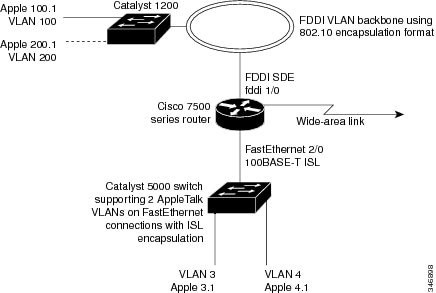
As shown in the figure above, AppleTalk traffic is routed to and from
switched VLAN domains 3, 4, 100, and 200 to any other AppleTalk routing
interface. This example shows a sample configuration file for the Cisco 7500
series router with the commands entered to configure the network shown in the
figure above.
Cisco 7500 Router Configuration
!
appletalk routing
interface Fddi 1/0.100
 encapsulation sde 100
 appletalk cable-range 100-100 100.2
 appletalk zone 100
!
interface Fddi 1/0.200
 encapsulation sde 200
 appletalk cable-range 200-200 200.2
 appletalk zone 200
!
interface FastEthernet 2/0.3
 encapsulation isl 3
 appletalk cable-range 3-3 3.2
 appletalk zone 3
!
interface FastEthernet 2/0.4
 encapsulation isl 4
 appletalk cable-range 4-4 4.2
 appletalk zone 4
!
Banyan VINES Routing over ISL Configuration Example
To configure routing of the Banyan VINES protocol over ISL trunks, you need to define ISL as the encapsulation type. This
example shows Banyan VINES configured to be routed over an ISL trunk:
vines routing
interface fastethernet 0.1
 encapsulation isl 100
 vines metric 2
DECnet Routing over ISL Configuration Example
To configure routing the DECnet protocol over ISL trunks, you need to define ISL as the encapsulation type. This example shows
DECnet configured to be routed over an ISL trunk:
decnet routing 2.1
interface fastethernet 1/0.1
 encapsulation isl 200
 decnet cost 4
HSRP over ISL Configuration Example
The configuration example shown in the figure below shows HSRP being
used on two VLAN routers sending traffic to and from ISL VLANs through a
Catalyst 5000 switch. Each router forwards its own traffic and acts as a
standby for the other.
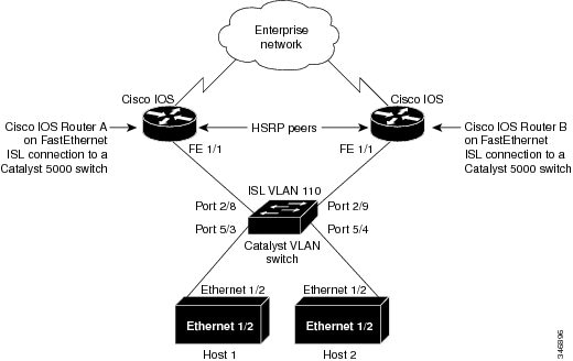
The topology shown in the figure above shows a Catalyst VLAN switch
supporting Fast Ethernet connections to two routers running HSRP. Both routers
are configured to route HSRP over ISLs.
The standby conditions are determined by the standby commands used in
the configuration. Traffic from Host 1 is forwarded through Router A. Because
the priority for the group is higher, Router A is the active router for Host 1.
Because the priority for the group serviced by Host 2 is higher in Router B,
traffic from Host 2 is forwarded through Router B, making Router B its active
router.
In the configuration shown in the figure above, if the active router
becomes unavailable, the standby router assumes active status for the
additional traffic and automatically routes the traffic normally handled by the
router that has become unavailable.
Host 1 Configuration
interface Ethernet 1/2
 ip address 10.1.1.25 255.255.255.0
 ip route 0.0.0.0 0.0.0.0 10.1.1.101
Host 2 Configuration
interface Ethernet 1/2
 ip address 10.1.1.27 255.255.255.0
 ip route 0.0.0.0 0.0.0.0 10.1.1.102
!
Router A Configuration
interface FastEthernet 1/1.110
 encapsulation isl 110
 ip address 10.1.1.2 255.255.255.0
 standby 1 ip 10.1.1.101
 standby 1 preempt
 standby 1 priority 105
 standby 2 ip 10.1.1.102
 standby 2 preempt
!
end
!
Router B Configuration
interface FastEthernet 1/1.110
 encapsulation isl 110
 ip address 10.1.1.3 255.255.255.0
 standby 1 ip 10.1.1.101
 standby 1 preempt
 standby 2 ip 10.1.1.102
 standby 2 preempt
 standby 2 priority 105
router igrp 1
!
network 10.1.0.0
network 10.2.0.0
!
VLAN Switch Configuration
set vlan 110 5/4
set vlan 110 5/3
set trunk 2/8 110
set trunk 2/9 110
IP Routing with RIF Between TrBRF VLANs Example
The figure below shows IP routing with RIF between two TrBRF VLANs.
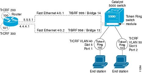
The following is the configuration for the router:
interface FastEthernet4/0.1
 ip address 10.5.5.1 255.255.255.0
 encapsulation tr-isl trbrf-vlan 999 bridge-num 14
 multiring trcrf-vlan 200 ring 100
 multiring all
!
 interface FastEthernet4/0.2
 ip address 10.4.4.1 255.255.255.0
 encapsulation tr-isl trbrf-vlan 998 bridge-num 13
 multiring trcrf-vlan 300 ring 101
 multiring all
The following is the configuration for the Catalyst 5000 switch with
the Token Ring switch module in slot 5. In this configuration, the Token Ring
port 102 is assigned with TrCRF VLAN 40 and the Token Ring port 103 is assigned
with TrCRF VLAN 50:
#vtp
set vtp domain trisl
set vtp mode server
set vtp v2 enable
#drip
set set tokenring reduction enable
set tokenring distrib-crf disable
#vlans
set vlan 999 name trbrf type trbrf bridge 0xe stp ieee
set vlan 200 name trcrf200 type trcrf parent 999 ring 0x64 mode srb
set vlan 40 name trcrf40 type trcrf parent 999 ring 0x66 mode srb
set vlan 998 name trbrf type trbrf bridge 0xd stp ieee
set vlan 300 name trcrf300 type trcrf parent 998 ring 0x65 mode srb
set vlan 50 name trcrf50 type trcrf parent 998 ring 0x67 mode srb
#add token port to trcrf 40
set vlan 40   5/1
#add token port to trcrf 50
set vlan 50   5/2
set trunk 1/2 on
IP Routing Between a TRISL VLAN and an Ethernet ISL VLAN Example
The figure below shows IP routing between a TRISL VLAN and an
Ethernet ISL VLAN.
VLAN
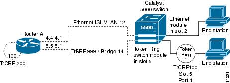
The following is the configuration for the router:
interface FastEthernet4/0.1
 ip address 10.5.5.1 255.255.255.0
 encapsulation tr-isl trbrf-vlan 999 bridge-num 14
 multiring trcrf-vlan 20 ring 100
 multiring all
!
interface FastEthernet4/0.2
 ip address 10.4.4.1 255.255.255.0
 encapsulation isl 12
IPX Routing over ISL Configuration Example
The figure below shows IPX interior encapsulations configured over
ISL encapsulation in VLAN configurations. Note that three different IPX
encapsulation formats are used. VLAN 20 uses SAP encapsulation, VLAN 30 uses
ARPA, and VLAN 70 uses novell-ether encapsulation. Prior to the introduction of
this feature, only the default encapsulation format, “novell-ether,” was
available for routing IPX over ISL links in VLANs.
Configurations
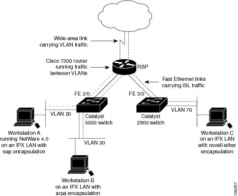
VLAN 20 Configuration
ipx routing
interface FastEthernet 2/0
 no shutdown
interface FastEthernet 2/0.20
 encapsulation isl 20
 ipx network 20 encapsulation sap
VLAN 30 Configuration
ipx routing
interface FastEthernet 2/0
 no shutdown
interface FastEthernet 2/0.30
 encapsulation isl 30
 ipx network 30 encapsulation arpa
VLAN 70 Configuration
ipx routing
interface FastEthernet 3/0
 no shutdown
interface Fast3/0.70
 encapsulation isl 70
 ipx network 70 encapsulation novell-ether
IPX Routing on FDDI Interfaces with SDE Example
The following example enables IPX routing on FDDI interfaces 0.2 and 0.3 with SDE. On FDDI interface 0.2, the encapsulation
type is SNAP. On FDDI interface 0.3, the encapsulation type is Novell’s FDDI_RAW.
ipx routing
interface fddi 0.2 enc sde 2
 ipx network f02 encapsulation snap
interface fddi 0.3 enc sde 3
 ipx network f03 encapsulation novell-fddi
Routing with RIF Between a TRISL VLAN and a Token Ring Interface Example
The figure below shows routing with RIF between a TRISL VLAN and a
Token Ring interface.
Interface
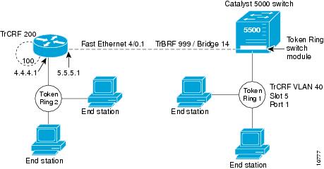
The following is the configuration for the router:
source-bridge ring-group 100
!
interface TokenRing 3/1
 ip address 10.4.4.1 255.255.255.0
!
interface FastEthernet4/0.1
 ip address 10.5.5.1 255.255.255.0
 encapsulation tr-isl trbrf 999 bridge-num 14
 multiring trcrf-vlan 200 ring-group 100
 multiring all
The following is the configuration for the Catalyst 5000 switch with
the Token Ring switch module in slot 5. In this configuration, the Token Ring
port 1 is assigned to the TrCRF VLAN 40:
#vtp
set vtp domain trisl
set vtp mode server
set vtp v2 enable
#drip
set set tokenring reduction enable
set tokenring distrib-crf disable
#vlans
set vlan 999 name trbrf type trbrf bridge 0xe stp ieee
set vlan 200 name trcrf200 type trcrf parent 999 ring 0x64 mode srt
set vlan 40 name trcrf40 type trcrf parent 999 ring 0x1 mode srt
#add token port to trcrf 40
set vlan 40   5/1
set trunk 1/2 on
VIP Distributed Switching over ISL Configuration Example
The figure below shows a topology in which Catalyst VLAN switches are
connected to routers forwarding traffic from a number of ISL VLANs. With the
VIP distributed ISL capability in the Cisco 7500 series router, each VIP card
can route ISL-encapsulated VLAN IP traffic. The inter-VLAN routing capacity is
increased linearly by the packet-forwarding capability of each VIP card.
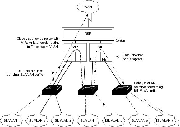
In the figure above, the VIP cards forward the traffic between ISL
VLANs or any other routing interface. Traffic from any VLAN can be routed to
any of the other VLANs, regardless of which VIP card receives the traffic.
These commands show the configuration for each of the VLANs shown in
the figure above:
interface FastEthernet1/0/0
 ip address 10.1.1.1 255.255.255.0
 ip route-cache distributed
 full-duplex
interface FastEthernet1/0/0.1
 ip address 10.1.1.1 255.255.255.0
 encapsulation isl 1
interface FastEthernet1/0/0.2
 ip address 10.1.2.1 255.255.255.0
 encapsulation isl 2
interface FastEthernet1/0/0.3
 ip address 10.1.3.1 255.255.255.0
 encapsulation isl 3
interface FastEthernet1/1/0
 ip route-cache distributed
 full-duplex
interface FastEthernet1/1/0.1
 ip address 172.16.1.1 255.255.255.0
 encapsulation isl 4
interface Fast Ethernet 2/0/0
 ip address 10.1.1.1 255.255.255.0
 ip route-cache distributed
 full-duplex
interface FastEthernet2/0/0.5
 ip address 10.2.1.1 255.255.255.0
 encapsulation isl 5
interface FastEthernet2/1/0
 ip address 10.3.1.1 255.255.255.0
 ip route-cache distributed
 full-duplex
interface FastEthernet2/1/0.6
 ip address 10.4.6.1 255.255.255.0
 encapsulation isl 6
interface FastEthernet2/1/0.7
 ip address 10.4.7.1 255.255.255.0
 encapsulation isl 7
XNS Routing over ISL Configuration Example
To configure routing of the XNS protocol over ISL trunks, you need to define ISL as the encapsulation type. This example shows
XNS configured to be routed over an ISL trunk:
xns routing 0123.4567.adcb
interface fastethernet 1/0.1
 encapsulation isl 100
 xns network 20
CLNS Routing over ISL Configuration Example
To configure routing of the CLNS protocol over ISL trunks, you need to define ISL as the encapsulation type. This example
shows CLNS configured to be routed over an ISL trunk:
clns routing
interface fastethernet 1/0.1
 encapsulation isl 100
 clns enable
IS-IS Routing over ISL Configuration Example
To configure IS-IS routing over ISL trunks, you need to define ISL as the encapsulation type. This example shows IS-IS configured
over an ISL trunk:
isis routing test-proc2
net 49.0001.0002.aaaa.aaaa.aaaa.00
interface fastethernet 2.0
 encapsulation isl 101
 clns router is-is test-proc2
Routing IEEE 802.10 Configuration Example
The figure below shows AppleTalk being routed between different ISL
and IEEE 802.10 VLAN encapsulating subinterfaces.
As shown in the figure above, AppleTalk traffic is routed to and from
switched VLAN domains 3, 4, 100, and 200 to any other AppleTalk routing
interface. This example shows a sample configuration file for the Cisco 7500
series router with the commands entered to configure the network shown in the
figure above.
Cisco 7500 Router Configuration
!
interface Fddi 1/0.100
 encapsulation sde 100
 appletalk cable-range 100-100 100.2
 appletalk zone 100
!
interface Fddi 1/0.200
 encapsulation sde 200
 appletalk cable-range 200-200 200.2
 appletalk zone 200
!
interface FastEthernet 2/0.3
 encapsulation isl 3
 appletalk cable-range 3-3 3.2
 appletalk zone 3
!
interface FastEthernet 2/0.4
 encapsulation isl 4
 appletalk cable-range 4-4 4.2
 appletalk zone 4
!
IEEE 802.1Q Encapsulation Configuration Examples
Configuration examples for each protocols are provided in the following sections:
Configuring AppleTalk over IEEE 802.1Q Example
This configuration example shows AppleTalk being routed on VLAN 100:
!
appletalk routing
!
interface fastethernet 4/1.100
  encapsulation dot1q 100
  appletalk cable-range 100-100 100.1
  appletalk zone eng
!
Configuring IP Routing over IEEE 802.1Q Example
This configuration example shows IP being routed on VLAN 101:
!
ip routing
!
interface fastethernet 4/1.101
  encapsulation dot1q 101
  ip addr 10.0.0.11 255.0.0.0
!
Configuring IPX Routing over IEEE 802.1Q Example
This configuration example shows IPX being routed on VLAN 102:
!
ipx routing
!
interface fastethernet 4/1.102
  encapsulation dot1q 102
  ipx network 100
!
VLAN 100 for Bridge Group 1 with Default VLAN1 Example
The following example configures VLAN 100 for bridge group 1 with a default VLAN1:
interface FastEthernet 4/1.100
encapsulation dot1q 1
bridge-group 1
VLAN 20 for Bridge Group 1 with Native VLAN Example
The following example configures VLAN 20 for bridge group 1 as a native VLAN:
interface FastEthernet 4/1.100
encapsulation dot1q 20 native
bridge-group 1
VLAN ISL or IEEE 802.1Q Routing Example
The following example configures VLAN ISL or IEEE 802.10 routing:
ipx routing
appletalk routing
!
interface Ethernet 1
ip address 10.1.1.1 255.255.255.0
appletalk cable-range 1-1 1.1
appletalk zone 1
ipx network 10 encapsulation snap
!
router igrp 1
network 10.1.0.0
!
end
!
#Catalyst5000
!
set VLAN 110 2/1
set VLAN 120 2/2
!
set trunk 1/1 110,120
# if 802.1Q, set trunk 1/1 nonegotiate 110, 120
!
end
!
ipx routing
appletalk routing
!
interface FastEthernet 1/1.110
encapsulation isl 110
!if 802.1Q, encapsulation dot1Q 110
ip address 10.1.1.2 255.255.255.0
appletalk cable-range 1.1 1.2
appletalk zone 1
ipx network 110 encapsulation snap
!
interface FastEthernet 1/1.120
encapsulation isl 120
!if 802.1Q, encapsulation dot1Q 120
ip address 10.2.1.2 255.255.255.0
appletalk cable-range 2-2 2.2
appletalk zone 2
ipx network 120 encapsulation snap
!
router igrp 1
network 10.1.0.0
network 10.2.1.0.0
!
end
!
ipx routing
appletalk routing
!
interface Ethernet 1
ip address 10.2.1.3 255.255.255.0
appletalk cable-range 2-2 2.3
appletalk zone 2
ipx network 120 encapsulation snap
!
router igrp 1
network 10.2.0.0
!
end
VLAN IEEE 802.1Q Bridging Example
The following examples configures IEEE 802.1Q bridging:
interface FastEthernet4/0
 no ip address
 no ip route-cache
 half-duplex
!
interface FastEthernet4/0.100
 encapsulation dot1Q 100
 no ip route-cache
 bridge-group 1
!
interface FastEthernet4/0.200
 encapsulation dot1Q 200 native
 no ip route-cache
 bridge-group 2
!
interface FastEthernet4/0.300
 encapsulation dot1Q 1
 no ip route-cache
 bridge-group 3
!
interface FastEthernet10/0
 no ip address
 no ip route-cache
 half-duplex
!
interface FastEthernet10/0.100
 encapsulation dot1Q 100
 no ip route-cache
 bridge-group 1
!
interface Ethernet11/3
 no ip address
 no ip route-cache
 bridge-group 2
!
interface Ethernet11/4
 no ip address
 no ip route-cache
 bridge-group 3
!
bridge 1 protocol ieee
bridge 2 protocol ieee
bridge 3 protocol ieee
VLAN IEEE 802.1Q IRB Example
The following examples configures IEEE 802.1Q integrated routing and bridging:
ip cef
appletalk routing
ipx routing 0060.2f27.5980
!
bridge irb
!
interface TokenRing3/1
 no ip address
 ring-speed 16
 bridge-group 2
!
interface FastEthernet4/0
 no ip address
 half-duplex
!
interface FastEthernet4/0.100
 encapsulation dot1Q 100
 bridge-group 1
!
interface FastEthernet4/0.200
 encapsulation dot1Q 200
 bridge-group 2
!
interface FastEthernet10/0
ip address 10.3.1.10 255.255.255.0
 half-duplex
 appletalk cable-range 200-200 200.10
 appletalk zone irb
 ipx network 200
!
interface Ethernet11/3
 no ip address
 bridge-group 1
!
interface BVI 1
 ip address 10.1.1.11 255.255.255.0
 appletalk cable-range 100-100 100.11
 appletalk zone bridging
 ipx network 100
!
router rip
 network 10.0.0.0
 network 10.3.0.0
!
bridge 1 protocol ieee
 bridge 1 route appletalk
 bridge 1 route ip
 bridge 1 route ipx
bridge 2 protocol ieee
!
Configuring IEEE 802.1Q-in-Q VLAN Tag Termination Example
Some ambiguous subinterfaces can use the
any keyword for the inner VLAN ID
specification. The
any keyword represents any inner VLAN ID that
is not explicitly configured on any other interface. In the following example,
seven subinterfaces are configured with various outer and inner VLAN IDs.
Note |
The |
interface GigabitEthernet1/0/0.1
 encapsulation dot1q 100 second-dot1q 100
interface GigabitEthernet1/0/0.2
 encapsulation dot1q 100 second-dot1q 200
interface GigabitEthernet1/0/0.3
 encapsulation dot1q 100 second-dot1q 300-400,500-600
interface GigabitEthernet1/0/0.4
 encapsulation dot1q 100 second-dot1q any
interface GigabitEthernet1/0/0.5
 encapsulation dot1q 200 second-dot1q 50
interface GigabitEthernet1/0/0.6
 encapsulation dot1q 200 second-dot1q 1000-2000,3000-4000
interface GigabitEthernet1/0/0.7
 encapsulation dot1q 200 second-dot1q any
The table below shows which subinterfaces are mapped to different
values of the outer and inner VLAN ID on Q-in-Q frames that come in on Gigabit
Ethernet interface 1/0/0.
|
Outer VLAN ID |
Inner VLAN ID |
Subinterface mapped to |
|---|---|---|
|
100 |
1 through 99 |
GigabitEthernet1/0/0.4 |
|
100 |
100 |
GigabitEthernet1/0/0.1 |
|
100 |
101 through 199 |
GigabitEthernet1/0/0.4 |
|
100 |
200 |
GigabitEthernet1/0/0.2 |
|
100 |
201 through 299 |
GigabitEthernet1/0/0.4 |
|
100 |
300 through 400 |
GigabitEthernet1/0/0.3 |
|
100 |
401 through 499 |
GigabitEthernet1/0/0.4 |
|
100 |
500 through 600 |
GigabitEthernet1/0/0.3 |
|
100 |
601 through 4095 |
GigabitEthernet1/0/0.4 |
|
200 |
1 through 49 |
GigabitEthernet1/0/0.7 |
|
200 |
50 |
GigabitEthernet1/0/0.5 |
|
200 |
51 through 999 |
GigabitEthernet1/0/0.7 |
|
200 |
1000 through 2000 |
GigabitEthernet1/0/0.6 |
|
200 |
2001 through 2999 |
GigabitEthernet1/0/0.7 |
|
200 |
3000 through 4000 |
GigabitEthernet1/0/0.6 |
|
200 |
4001 through 4095 |
GigabitEthernet1/0/0.7 |
A new subinterface is now configured:
interface GigabitEthernet1/0/0.8
 encapsulation dot1q 200 second-dot1q 200-600,900-999
The table below shows the changes made to the table for the outer
VLAN ID of 200. Notice that subinterface 1/0/0.7 configured with the
any keyword now has new inner VLAN ID
mappings.
|
Outer VLAN ID |
Inner VLAN ID |
Subinterface mapped to |
|---|---|---|
|
200 |
1 through 49 |
GigabitEthernet1/0/0.7 |
|
200 |
50 |
GigabitEthernet1/0/0.5 |
|
200 |
51 through 199 |
GigabitEthernet1/0/0.7 |
|
200 |
200 through 600 |
GigabitEthernet1/0/0.8 |
|
200 |
601 through 899 |
GigabitEthernet1/0/0.7 |
|
200 |
900 through 999 |
GigabitEthernet1/0/0.8 |
|
200 |
1000 through 2000 |
GigabitEthernet1/0/0.6 |
|
200 |
2001 through 2999 |
GigabitEthernet1/0/0.7 |
|
200 |
3000 through 4000 |
GigabitEthernet1/0/0.6 |
|
200 |
4001 through 4095 |
GigabitEthernet1/0/0.7 |
Additional References
The following sections provide references related to the Managed LAN Switch feature.
Related Documents
|
Related Topic |
Document Title |
|---|---|
|
IP LAN switching commands: complete command syntax, command mode, defaults, usage guidelines, and examples |
Cisco IOS LAN Switching Services Command Reference |
|
LAN switching |
“LAN Switching” module of the |
Standards
|
Standards |
Title |
|---|---|
|
No new or modified RFCs are supported by this feature, and support for existing standards has not been modified by this feature. |
— |
MIBs
|
MIBs |
MIBs Link |
|---|---|
|
No new or modified MIBs are supported by this feature, and support for existing MIBs has not been modified by this feature. |
To locate and download MIBs for selected platforms, Cisco IOS releases, and feature sets, use Cisco MIB Locator found at http://www.cisco.com/go/mibs |
RFCs
|
RFCs |
Title |
|---|---|
|
No new or modified RFCs are supported by this feature, and support for existing standards has not been modified by this feature. |
— |
Technical Assistance
|
Description |
Link |
|---|---|
|
The Cisco Support website provides extensive online resources, including documentation and tools for troubleshooting and To receive security and technical information about your products, you can subscribe to various services, such as the Product Access to most tools on the Cisco Support website requires a Cisco.com user ID and password. |
http://www.cisco.com/cisco/web/support/index.html |
Feature Information for Routing Between VLANs
The following table provides release information about the feature or features described in this module. This table lists
only the software release that introduced support for a given feature in a given software release train. Unless noted otherwise,
subsequent releases of that software release train also support that feature.
Use Cisco Feature Navigator to find information about platform support and Cisco software image support. To access Cisco
Feature Navigator, go to www.cisco.com/go/cfn. An account on Cisco.com is not required.
|
Feature Name |
Releases |
Feature Information |
|---|---|---|
|
IEEE 802.1Q-in-Q VLAN Tag Termination |
12.0(28)S, 12.3(7)(X17) 12.0(32)S1, 12.2(31)SB 12.3(7)T 12.3((7)XI1 |
Encapsulating IEEE 802.1Q VLAN tags within 802.1Q enables service providers to use a single VLAN to support customers who |
|
Configuring Routing Between VLANs with IEEE 802.1Q Encapsulation |
12.0(7)XE 12.1(5)T 12.2(2)DD 12.2(4)B 12.2(8)T 12.2(13)T Cisco IOS XE 3.8(S) Cisco IOS XE 3.9(S) |
The IEEE 802.1Q protocol is used to interconnect multiple switches and routers, and for defining VLAN topologies. The IEEE In Cisco IOS XE Release 3.8(S), support was added for the Cisco ISR 4400 Series Routers. In Cisco IOS XE Release 3.9(S), support was added for the Cisco CSR 1000V Series Routers. |
|
Configuring Routing Between VLANs with Inter-Switch Link Encapsulation |
12.0(7)XE 12.1(5)T 12.2(2)DD 12.2(4)B 12.2(8)T 12.2(13)T |
ISL is a Cisco protocol for interconnecting multiple switches and maintaining VLAN information as traffic goes between switches. |
|
Configuring Routing Between VLANs with IEEE 802.10 Encapsulation |
12.0(7)XE 12.1(5)T 12.2(2)DD 12.2(4)B 12.2(8)T 12.2(13)T |
AppleTalk can be routed over VLAN subinterfaces using the ISL or IEEE 802.10 VLANs feature that provides full-feature Cisco |
|
VLAN Range |
12.0(7)XE 12.1(5)T 12.2(2)DD 12.2(4)B 12.2(8)T 12.2(13)T |
Using the VLAN Range feature, you can group VLAN subinterfaces together so that any command entered in a group applies to In Cisco IOS Release 12.0(7)XE, the The In Cisco IOS Release 12.2(2)DD, the The The VLAN Range feature was integrated into Cisco IOS Release 12.2(8)T. This VLAN Range feature was integrated into Cisco IOS Release 12.2(13)T. |
|
256+ VLANS |
12.1(2)E, 12.2(8)T Cisco IOS XE 3.8(S) Cisco IOS XE 3.9(S) |
The 256+ VLAN feature enables a device to route In Cisco IOS XE Release 3.8(S), support was added for the Cisco ISR 4400 Series Routers. In Cisco IOS XE Release 3.9(S), support was added for the Cisco CSR 1000V Series Routers. |
Январь 5, 2015
Read the article CONFIGURING INTERVLAN ROUTING ON CISCO ROUTERS (ROUTER ON A STICK) in ![]() English
English
Для настройки взаимодействия между несколькими виртуальными сетями (Vlan), расположенными на одном коммутаторе, необходим маршрутизатор, подключенный к коммутатору через Trunk порт. При передаче трафика по этому порту каждый пакет помечается номером Vlan, которому принадлежит. Это позволяет устройствам корректно перенаправлять пакеты.
На этом интерфейсе настраиваются сабинтерфейсы (subinterfaces) с соответствующими ip адресами для каждой из сетей Vlan.
Ниже приведен пример настройки Trunk порта маршрутизатора Cisco 2811 для связи с коммутатором.

Видео версия этой статьи
Зайдите в режим конфигурирования (conf t)
R-DELTACONFIG#conf t
Выберите интерфейс FastEthernet0/0 и очистите его
interface FastEthernet0/0

no shut

no ip address
Настройка интерфейса для сети управления оборудованием. Здесь не ставим точку после названия и не указываем идентификатор. Vlan. Это Vlan 1 по умолчанию.
interface FastEthernet0/0

ip address 192.168.1.1 255.255.255.0
Настройка сабинтерфейса для сети отдела продаж
interface FastEthernet0/0.10

encapsulation dot1q 10

ip address 192.168.10.1 255.255.255.0

description Sales
Настройка сабинтерфейса для сети бухгалтерии
interface FastEthernet0/0.20

encapsulation dot1q 20

ip address 192.168.20.1 255.255.255.0

description Account
Настройка сабинтерфейса для сети администраторов
interface FastEthernet0/0.100

encapsulation dot1q 100

ip address 192.168.100.1 255.255.255.0

description Admins
Важно!
На каждом интерфейсе рекомендую подписывать предназначения сетей командой description. Это поле никак не влияет на другие настройки, однако делает конфигурацию более удобной для восприятия.
Важно!
Обратите внимание, что рядом с указанием инкапсуляции (encapsulation dot1q 20) и в названии сабинтерфейса (interface FastEthernet0/0.20) стоит цифра, обозначающая номер Vlan (20). При этом порядковый номер сабинтерфейса может быть любым, но в строчке с настройкой инкапсуляции обязательно должен быть номер того Vlan, которому принадлежит сеть.
На коммутаторе помимо access портов, к которым подключены пользователи различных Vlan, должен быть сконфигурирован такой же trunk порт. (Как это сделать описано здесь)
Убедившись, что на коммутаторе настроен trunk порт и созданы Vlan с соответствующими номерами (10, 20 и 100), следует соединить его с интерфейсом FastEthernet0/0 маршрутизатора.
Для взаимодействия устройств из разных Vlan необходимо, чтобы:
- каждая рабочая станция была подключена к порту коммутатора, на котором настроен соответствующий ей Vlan
- На портах, куда подключаются рабочие станции должны присутствовать строчки вида
switchport access vlan Х
Например для бухгалтерии:
switchport access vlan 20 - каждая рабочая станция должна иметь ip адрес в соответствующей сети
Рабочая станция в отделе продаж будет иметь адрес 192.168.10.5 255.255.255.0 - на каждой рабочей станции в сетевых настройках в качестве шлюза по умолчанию должен быть указан ip адрес сабинтерфейса маршрутизатора того же Vlan, что и рабочая станция. Например для сети отдела продаж это 192.168.10.1
- все используемые порты коммутатора и маршрутизатора должны быть включены
Команда show ip inter brief покажет состояния всех интерфейсов. Используемые должны быть в состоянии Up/Up.
Результатом настройки должна стать доступность друг другу всех объектов сети (как рабочих станций, так и интерфейсов маршрутизатора). Проверять следует командой ping с любого хоста или маршрутизатора.

Важно!
Не забудьте сохранить конфигурацию всех устройств командой write или copy run start. Иначе после перезагрузки все изменения будут потеряны.
R-DELTACONFIG#write

Building configuration...

[OK]
Перейти к оглавлению
Материал из Xgu.ru
Перейти к: навигация, поиск
- Короткий URL: vlan/cisco
- Автор: Наташа Самойленко
< VLAN
На этой странице рассматривается процедура настройки VLAN в Cisco.
На странице VLAN в Cisco/Lab находятся лабораторные, которые можно сделать для того чтобы на практике попробовать настройки, которые описываются на этой странице. Лабораторные подготовлены в Packet Tracer, но аналогично могут быть выполнены и на реальном оборудовании.
Содержание
- 1 Настройка VLAN на коммутаторах Cisco под управлением IOS
- 1.1 Настройка access портов
- 1.2 Настройка транка (trunk)
- 1.2.1 Настройка статического транка
- 1.2.2 Динамическое создание транков (DTP)
- 1.2.3 Разрешённые VLAN’ы
- 1.2.4 Native VLAN
- 1.3 Настройка маршрутизации между VLAN
- 1.4 Перевод интерфейса в режим 3го уровня
- 1.5 Просмотр информации
- 1.6 Диапазоны VLAN
- 1.7 Пример настройки
- 1.7.1 Пример базовой настройки VLAN, без настройки маршрутизации
- 1.7.2 Пример конфигураций с настройкой маршрутизации между VLAN
- 2 Настройка VLAN на маршрутизаторах Cisco
- 2.1 Пример настройки
- 2.2 Настройка native VLAN
- 3 Примечания
[править] Настройка VLAN на коммутаторах Cisco под управлением IOS

![]()
Сеть с VLANами на коммутаторах Cisco
Терминология Cisco:
- access port — порт принадлежащий одному VLAN’у и передающий нетегированный трафик
- trunk port — порт передающий тегированный трафик одного или нескольких VLAN’ов
Коммутаторы Cisco ранее поддерживали два протокола 802.1Q и ISL. ISL — проприетарный протокол использующийся в оборудовании Cisco. ISL полностью инкапсулирует фрейм для передачи информации о принадлежности к VLAN’у.
В современных моделях коммутаторов Cisco ISL не поддерживается.
Создание VLAN’а с идентификатором 2 и задание имени для него:
sw1(config)# vlan 2
sw1(config-vlan)# name test
Удаление VLAN’а с идентификатором 2:
sw1(config)# no vlan 2
[править] Настройка access портов
Назначение порта коммутатора в VLAN:
sw1(config)# interface fa0/1
sw1(config-if)# switchport mode access
sw1(config-if)# switchport access vlan 2
Назначение диапазона портов с fa0/4 до fa0/5 в vlan 10:
sw1(config)# interface range fa0/4 - 5
sw1(config-if-range)# switchport mode access
sw1(config-if-range)# switchport access vlan 10
Просмотр информации о VLAN’ах:
sw1# show vlan brief
VLAN Name                             Status    Ports

---- -------------------------------- --------- -------------------------------

1    default                          active    Fa0/6, Fa0/7, Fa0/8, Fa0/9,
                                                Fa0/10, Fa0/11, Fa0/12, Fa0/13,
                                                Fa0/14, Fa0/15, Fa0/16, Fa0/17,
                                                Fa0/18, Fa0/19, Fa0/20, Fa0/21,
                                                Fa0/22, Fa0/23, Fa0/24

2    test                             active    Fa0/1, Fa0/2

10   VLAN0010                         active    Fa0/4, Fa0/5

15   VLAN0015                         active    Fa0/3
[править] Настройка транка (trunk)
Для того чтобы передать через порт трафик нескольких VLAN, порт переводится в режим транка.
Режимы интерфейса (режим по умолчанию зависит от модели коммутатора):
- auto — Порт находится в автоматическом режиме и будет переведён в состояние trunk, только если порт на другом конце находится в режиме on или desirable. Т.е. если порты на обоих концах находятся в режиме «auto», то trunk применяться не будет.
- desirable — Порт находится в режиме «готов перейти в состояние trunk»; периодически передает DTP-кадры порту на другом конце, запрашивая удаленный порт перейти в состояние trunk (состояние trunk будет установлено, если порт на другом конце находится в режиме on, desirable, или auto).
- trunk — Порт постоянно находится в состоянии trunk, даже если порт на другом конце не поддерживает этот режим.
- nonegotiate — Порт готов перейти в режим trunk, но при этом не передает DTP-кадры порту на другом конце. Этот режим используется для предотвращения конфликтов с другим «не-cisco» оборудованием. В этом случае коммутатор на другом конце должен быть вручную настроен на использование trunk’а.
По умолчанию в транке разрешены все VLAN. Для того чтобы через соответствующий VLAN в транке передавались данные, как минимум, необходимо чтобы VLAN был активным.
Активным VLAN становится тогда, когда он создан на коммутаторе и в нём есть хотя бы один порт в состоянии up/up.
VLAN можно создать на коммутаторе с помощью команды vlan.
Кроме того, VLAN автоматически создается на коммутаторе в момент добавления в него интерфейсов в режиме access.
В схеме, которая используется для демонстрации настроек, на коммутаторах sw1 и sw2, нужные VLAN будут созданы в момент добавления access-портов в соответствующие VLAN:
sw1(config)# interface fa0/3
sw1(config-if)# switchport mode access
sw1(config-if)# switchport access vlan 15
% Access VLAN does not exist. Creating vlan 15
На коммутаторе sw3 access-портов нет. Поэтому необходимо явно создать все необходимые VLAN:
sw3(config)# vlan 2,10,15
Для автоматического создания VLAN на коммутаторах, может использоваться протокол VTP.
[править] Настройка статического транка
Создание статического транка:
sw1(config)# interface fa0/22
sw1(config-if)# switchport mode trunk
На некоторых моделях коммутаторов (на которых поддерживается ISL) после попытки перевести интерфейс в режим статического транка, может появится такая ошибка:
sw1(config-if)# switchport mode trunk
Command rejected: An interface whose trunk encapsulation is “Auto” can not be configured to “trunk” mode.
Это происходит из-за того, что динамическое определение инкапсуляции (ISL или 802.1Q) работает только с динамическими режимами транка. И для того, чтобы настроить статический транк, необходимо инкапсуляцию также настроить статически.
Для таких коммутаторов необходимо явно указать тип инкапсуляции для интерфейса:
sw1(config-if)# switchport trunk encapsulation dot1q
И после этого снова повторить команду настройки статического транка (switchport mode trunk).
[править] Динамическое создание транков (DTP)
Dynamic Trunk Protocol (DTP) — проприетарный протокол Cisco, который позволяет коммутаторам динамически распознавать настроен ли соседний коммутатор для поднятия транка и какой протокол использовать (802.1Q или ISL). Включен по умолчанию.
Режимы DTP на интерфейсе:
- auto — Порт находится в автоматическом режиме и будет переведён в состояние trunk, только если порт на другом конце находится в режиме on или desirable. Т.е. если порты на обоих концах находятся в режиме «auto», то trunk применяться не будет.
- desirable — Порт находится в режиме «готов перейти в состояние trunk»; периодически передает DTP-кадры порту на другом конце, запрашивая удаленный порт перейти в состояние trunk (состояние trunk будет установлено, если порт на другом конце находится в режиме on, desirable, или auto).
- nonegotiate — Порт готов перейти в режим trunk, но при этом не передает DTP-кадры порту на другом конце. Этот режим используется для предотвращения конфликтов с другим «не-cisco» оборудованием. В этом случае коммутатор на другом конце должен быть вручную настроен на использование trunk’а.
Перевести интерфейс в режим auto:
sw1(config-if)# switchport mode dynamic auto
Перевести интерфейс в режим desirable:
sw1(config-if)# switchport mode dynamic desirable
Перевести интерфейс в режим nonegotiate:
sw1(config-if)# switchport nonegotiate
Проверить текущий режим DTP:
sw# show dtp interface
[править] Разрешённые VLAN’ы
По умолчанию в транке разрешены все VLAN.
Можно ограничить перечень VLAN, которые могут передаваться через конкретный транк.
Указать перечень разрешенных VLAN для транкового порта fa0/22:
sw1(config)# interface fa0/22
sw1(config-if)# switchport trunk allowed vlan 1-2,10,15
Добавление ещё одного разрешенного VLAN:
sw1(config)# interface fa0/22
sw1(config-if)# switchport trunk allowed vlan add 160
Удаление VLAN из списка разрешенных:
sw1(config)# interface fa0/22
sw1(config-if)# switchport trunk allowed vlan remove 160
[править] Native VLAN
В стандарте 802.1Q существует понятие native VLAN. Трафик этого VLAN передается нетегированным.
По умолчанию это VLAN 1. Однако можно изменить это и указать другой VLAN как native.
Настройка VLAN 5 как native:
sw1(config-if)# switchport trunk native vlan 5
Теперь весь трафик принадлежащий VLAN’у 5 будет передаваться через транковый интерфейс нетегированным, а весь пришедший на транковый интерфейс нетегированный трафик будет промаркирован как принадлежащий VLAN’у 5 (по умолчанию VLAN 1).
[править] Настройка маршрутизации между VLAN

![]()
Передача трафика между VLANами с помощью коммутатора Cisco
Все настройки по назначению портов в VLAN, сделанные ранее для sw1, sw2 и sw3, сохраняются.
Дальнейшие настройки подразумевают использование sw3 как коммутатора 3 уровня.
При такой схеме работы никаких дополнительных настроек на маршрутизаторе не требуется. Коммутатор осуществляет маршрутизацию между сетями разных VLAN, а на маршрутизатор отправляет трафик предназначенный в другие сети.
Настройки на коммутаторе sw3:
| VLAN / интерфейс 3го уровня | IP-адрес |
|---|---|
| VLAN 2 | 10.0.2.1 /24 |
| VLAN 10 | 10.0.10.1 /24 |
| VLAN 15 | 10.0.15.1 /24 |
| Fa 0/10 | 192.168.1.2 /24 |
Включение маршрутизации на коммутаторе:
sw3(config)# ip routing
Задание адреса в VLAN. Этот адрес будет маршрутом по умолчанию для компьютеров в VLAN 2:
sw3(config)# interface Vlan2
sw3(config-if)# ip address 10.0.2.1 255.255.255.0
sw3(config-if)# no shutdown
Задание адреса в VLAN 10:
sw3(config)# interface Vlan10
sw3(config-if)# ip address 10.0.10.1 255.255.255.0
sw3(config-if)# no shutdown
[править] Перевод интерфейса в режим 3го уровня
Интерфейс fa0/10 соединен с маршрутизатором. Этот интерфейс можно перевести в режим 3 уровня.
Перевод fa0/10 в режим интерфейса 3 уровня и задание IP-адреса:
sw3(config)#interface FastEthernet 0/10
sw3(config-if)# no switchport
sw3(config-if)# ip address 192.168.1.2 255.255.255.0
sw3(config-if)# no shutdown
R1 используется как шлюз по умолчанию для рассматриваемой сети. Трафик не предназначенный сетям VLAN’ов будет передаваться на R1.
Настройка маршрута по умолчанию:
sw3(config) ip route 0.0.0.0 0.0.0.0 192.168.1.1
[править] Просмотр информации
Просмотр информации о транке:
sw1# show interface fa0/22 trunk

Port                Mode         Encapsulation  Status        Native vlan
Fa0/22              on           802.1q         trunking      1

Port                Vlans allowed on trunk
Fa0/22              1-2,10,15

Port                Vlans allowed and active in management domain
Fa0/22              1-2,10,15

Port                Vlans in spanning tree forwarding state and not pruned
Fa0/22              1-2,10,15
Просмотр информации о настройках интерфейса (о транке):
sw1# show interface fa0/22 switchport
Name: Fa0/22
Switchport: Enabled
Administrative Mode: trunk
Operational Mode: trunk
Administrative Trunking Encapsulation: dot1q
Operational Trunking Encapsulation: dot1q
Operational Dot1q Ethertype:  0x8100
Negotiation of Trunking: On
Access Mode VLAN: 1 (default)
Trunking Native Mode VLAN: 1 (VLAN_1)
Administrative Native VLAN tagging: enabled
Operational Native VLAN tagging: disabled
Voice VLAN: none
Administrative private-vlan host-association: none
Administrative private-vlan mapping: none
Operational private-vlan: none
Trunking VLANs Enabled: ALL
Pruning VLANs Enabled: 2-1001
Capture Mode Disabled
Capture VLANs Allowed: ALL
Просмотр информации о настройках интерфейса (об access-интерфейсе):
sw1# show interface fa0/3 switchport
Name: Fa0/3
Switchport: Enabled
Administrative Mode: static access
Operational Mode: static access
Administrative Trunking Encapsulation: negotiate
Operational Trunking Encapsulation: native
Operational Dot1q Ethertype:  0x8100
Negotiation of Trunking: Off
Access Mode VLAN: 15 (VLAN0015)
Trunking Native Mode VLAN: 1 (default)
Administrative Native VLAN tagging: enabled
Operational Native VLAN tagging: disabled
Voice VLAN: none
Administrative private-vlan host-association: none
Administrative private-vlan mapping: none
Operational private-vlan: none
Trunking VLANs Enabled: ALL
Pruning VLANs Enabled: 2-1001
Capture Mode Disabled
Capture VLANs Allowed: ALL
Просмотр информации о VLAN’ах:
sw1# show vlan brief
VLAN Name                             Status    Ports

---- -------------------------------- --------- -------------------------------

1    default                          active    Fa0/6, Fa0/7, Fa0/8, Fa0/9,
                                                Fa0/10, Fa0/11, Fa0/12, Fa0/13,
                                                Fa0/14, Fa0/15, Fa0/16, Fa0/17,
                                                Fa0/18, Fa0/19, Fa0/20, Fa0/21,
                                                Fa0/22, Fa0/23, Fa0/24

2    test                             active    Fa0/1, Fa0/2

10   VLAN0010                         active    Fa0/4, Fa0/5

15   VLAN0015                         active    Fa0/3
[править] Диапазоны VLAN
| VLANs | Диапазон | Использование | Передается VTP |
|---|---|---|---|
| 0, 4095 | Reserved | Только для системного использования. | — |
| 1 | Normal | VLAN по умолчанию. Можно использовать, но нельзя удалить. | Да |
| 2-1001 | Normal | Для VLANов Ethernet. Можно создавать, удалять и использовать. | Да |
| 1002-1005 | Normal | Для FDDI и Token Ring. Нельзя удалить. | Да |
| 1006-4094 | Extended | Только для VLANов Ethernet. | Версия 1 и 2 нет, версия 3 да |
[править] Пример настройки
[править] Пример базовой настройки VLAN, без настройки маршрутизации
В этом разделе приведены конфигурационные файлы коммутаторов для изображенной схемы.
На коммутаторе sw3 не настроена маршрутизация между VLAN, поэтому в данной схеме хосты могут общаться только в пределах одного VLAN.
Например, хосты на коммутаторе sw1 в VLAN 2 могут взаимодействовать между собой и с хостами в VLAN 2 на коммутаторе sw2. Однако, они не могут взаимодействовать с хостами в других VLAN на коммутаторах sw1 и sw2.
Не все настройки являются обязательными. Например, перечисление разрешенных VLAN в транке не является обязательным для работы транка, однако, рекомендуется настраивать разрешенные VLAN явно.
Настройки транка на sw1 и sw2 немного отличаются от sw3. На sw3 не задается инкапсуляция для транка (команда switchport trunk encapsulation dot1q), так как в используемой модели коммутатора поддерживается только режим 802.1Q.
Конфигурация sw1:
!
interface FastEthernet0/1
 switchport mode access
 switchport access vlan 2
!
interface FastEthernet0/2
 switchport mode access
 switchport access vlan 2
!
interface FastEthernet0/3
 switchport mode access
 switchport access vlan 15
!
interface FastEthernet0/4
 switchport mode access
 switchport access vlan 10
!
interface FastEthernet0/5
 switchport mode access
 switchport access vlan 10
!
interface FastEthernet0/22
 switchport trunk encapsulation dot1q
 switchport mode trunk
 switchport trunk allowed vlan 1,2,10,15
!
Конфигурация sw2:
!
interface FastEthernet0/1
 switchport mode access
 switchport access vlan 10
!
interface FastEthernet0/2
 switchport mode access
 switchport access vlan 2
!
interface FastEthernet0/3
 switchport mode access
 switchport access vlan 2
!
interface FastEthernet0/22
 switchport trunk encapsulation dot1q
 switchport mode trunk
 switchport trunk allowed vlan 1,2,10
!
Конфигурация sw3:
!
vlan 2,10,15
!
interface FastEthernet0/1
 switchport mode trunk
 switchport trunk allowed vlan 1,2,10,15
!
interface FastEthernet0/2
 switchport mode trunk
 switchport trunk allowed vlan 1,2,10
!
[править] Пример конфигураций с настройкой маршрутизации между VLAN
В этом разделе приведены конфигурационные файлы коммутаторов для изображенной схемы.
На коммутаторе sw3 настроена маршрутизация между VLAN, поэтому в данной схеме хосты могут общаться как в пределах одного VLAN, так и между различными VLAN.
Например, хосты на коммутаторе sw1 в VLAN 2 могут взаимодействовать между собой и с хостами в VLAN 2 на коммутаторе sw2. Кроме того, они могут взаимодействовать с хостами в других VLAN на коммутаторах sw1 и sw2.
Настройки коммутаторов sw1 и sw2 остались точно такими же, как и в предыдущем разделе.
Добавились дополнительные настройки только на коммутаторе sw3.
Конфигурация sw1:
!
interface FastEthernet0/1
 switchport mode access
 switchport access vlan 2
!
interface FastEthernet0/2
 switchport mode access
 switchport access vlan 2
!
interface FastEthernet0/3
 switchport mode access
 switchport access vlan 15
!
interface FastEthernet0/4
 switchport mode access
 switchport access vlan 10
!
interface FastEthernet0/5
 switchport mode access
 switchport access vlan 10
!
interface FastEthernet0/22
 switchport trunk encapsulation dot1q
 switchport mode trunk
 switchport trunk allowed vlan 1,2,10,15
!
Конфигурация sw2:
!
interface FastEthernet0/1
 switchport mode access
 switchport access vlan 10
!
interface FastEthernet0/2
 switchport mode access
 switchport access vlan 2
!
interface FastEthernet0/3
 switchport mode access
 switchport access vlan 2
!
interface FastEthernet0/22
 switchport trunk encapsulation dot1q
 switchport mode trunk
 switchport trunk allowed vlan 1,2,10
!
Конфигурация sw3:
!
ip routing
!
vlan 2,10,15
!
interface FastEthernet0/1
 switchport mode trunk
 switchport trunk allowed vlan 1,2,10,15
!
interface FastEthernet0/2
 switchport mode trunk
 switchport trunk allowed vlan 1,2,10
!
!
interface FastEthernet0/10
 no switchport
 ip address 192.168.1.2 255.255.255.0
!
!
interface Vlan2
 ip address 10.0.2.1 255.255.255.0
!
interface Vlan10
 ip address 10.0.10.1 255.255.255.0
!
interface Vlan15
 ip address 10.0.15.1 255.255.255.0
!
!
ip route 0.0.0.0 0.0.0.0 192.168.1.1
!
[править] Настройка VLAN на маршрутизаторах Cisco

![]()
Передача трафика между VLANами с помощью маршрутизатора
Передача трафика между VLAN может осуществляться с помощью маршрутизатора. Для того чтобы маршрутизатор мог передавать трафик из одного VLAN в другой (из одной сети в другую), необходимо, чтобы в каждой сети у него был интерфейс. Для того чтобы не выделять под сеть каждого VLAN отдельный физический интерфейс, создаются логические подынтерфейсы[1] на физическом интерфейсе для каждого VLAN.
На коммутаторе порт, ведущий к маршрутизатору, должен быть настроен как тегированный порт (в терминах Cisco — транк).
Изображенная схема, в которой маршрутизация между VLAN выполняется на маршрутизаторе, часто называется router on a stick.
IP-адреса шлюза по умолчанию для VLAN (эти адреса назначаются на подынтерфейсах маршрутизатора R1):
| VLAN | IP-адрес |
|---|---|
| VLAN 2 | 10.0.2.1 /24 |
| VLAN 10 | 10.0.10.1 /24 |
| VLAN 15 | 10.0.15.1 /24 |
Для логических подынтерфейсов[1] необходимо указывать то, что интерфейс будет получать тегированный трафик и указывать номер VLAN соответствующий этому интерфейсу. Это задается командой в режиме настройки подынтерфейса:
R1(config-if)# encapsulation dot1q <vlan-id>
Создание логического подынтерфейса для VLAN 2:
R1(config)# interface fa0/0.2
R1(config-subif)# encapsulation dot1q 2
R1(config-subif)# ip address 10.0.2.1 255.255.255.0
Создание логического подынтерфейса для VLAN 10:
R1(config)# interface fa0/0.10
R1(config-subif)# encapsulation dot1q 10
R1(config-subif)# ip address 10.0.10.1 255.255.255.0
|
|
Соответствие номера подынтерфейса и номера VLAN не является обязательным условием. Однако обычно номера подынтерфейсов задаются именно таким образом, чтобы упростить администрирование. |
На коммутаторе порт, ведущий к маршрутизатору, должен быть настроен как статический транк:
interface FastEthernet0/20
 switchport trunk encapsulation dot1q
 switchport mode trunk
[править] Пример настройки
Конфигурационные файлы устройств для схемы изображенной в начале раздела.
Конфигурация sw1:
!
interface FastEthernet0/1
 switchport mode access
 switchport access vlan 2
!
interface FastEthernet0/2
 switchport mode access
 switchport access vlan 2
!
interface FastEthernet0/3
 switchport mode access
 switchport access vlan 15
!
interface FastEthernet0/4
 switchport mode access
 switchport access vlan 10
!
interface FastEthernet0/5
 switchport mode access
 switchport access vlan 10
!
interface FastEthernet0/20
 switchport trunk encapsulation dot1q
 switchport mode trunk
 switchport trunk allowed vlan 2,10,15
!
Конфигурация R1:
!
interface fa0/0.2
 encapsulation dot1q 2
 ip address 10.0.2.1 255.255.255.0
!
interface fa0/0.10
 encapsulation dot1q 10
 ip address 10.0.10.1 255.255.255.0
!
interface fa0/0.15
 encapsulation dot1q 15
 ip address 10.0.15.1 255.255.255.0
!
[править] Настройка native VLAN
По умолчанию трафик VLAN’а 1 передается не тегированым (то есть, VLAN 1 используется как native), поэтому на физическом интерфейсе маршрутизатора задается адрес из сети VLAN 1.
Задание адреса на физическом интерфейсе:
R1(config)# interface fa0/0
R1(config-if)# ip address 10.0.1.1 255.255.255.0
Если необходимо создать подынтерфейс для передачи не тегированного трафика, то в этом подынтерфейсе явно указывается, что он принадлежит native VLAN. Например, если native VLAN 99:
R1(config)# interface fa0/0.99
R1(config-subif)# encapsulation dot1q 99 native
R1(config-subif)# ip address 10.0.99.1 255.255.255.0
[править] Примечания
- ↑ 1,0 1,1 Хотя глазу приятнее видеть написание слова как подинтерфейс, правильное написание всё же через букву ы; подробнее: [1]. Именно по этой причине правильно — субинтерфейс. Иностранному слову — ностранную приставку.
| |
|
|---|---|
| Устройства | Cisco 871 • Cisco Router • Cisco Switch • Сisco Сatalyst • Cisco IPS • Cisco ASA • PIX • Dynamips |
| Безопасность (коммутаторы и маршрутизаторы) |
Cisco Security • Port security • DHCP snooping • Dynamic ARP Protection • IP Source Guard • Аутентификация при доступе к сети • 802.1X в Cisco • Zone-Based Policy Firewall • Cisco NAT • NAT в Cisco • Cisco SSH |
| Cisco ASA | Cisco ASA/NAT • Cisco ASA/Troubleshooting • Cisco ASA/IPS • Cisco ASA failover • Cisco ASA/Transparent firewall • Cisco ASA/Site-to-Site_VPN • Cisco ASA/Easy_VPN • Cisco ASA/WebVPN • Объединение OSPF-сетей туннелем между двумя системами ASA (без GRE) • Центр сертификатов на Cisco ASA |
| VPN | IPsec в Cisco • Cisco IOS Site-to-Site VPN • DMVPN • Cisco Easy VPN • Cisco Web VPN • Cisco ipsec preshared |
| Канальный уровень | CDP • VLAN в Cisco • ISL • VTP • STP в Cisco • Cisco Express Forwarding • Агрегирование каналов • Зеркалирование трафика • QinQ • Frame Relay |
| Сетевой уровень | Маршрутизация в Cisco • RIP • EIGRP • IS-IS • OSPF • BGP • PIM • Multicast • GLBP • VRRP • HSRP • DHCP • IPv6 • IPv6 vs IPv4 • Резервирование Интернет-каналов без использования BGP • Использование BGP для резервирования Интернет-каналов |
| Разное | Режим ROMMON в Cisco • Опция 82 DHCP • 802.1X и RADIUS • SNMP в Cisco • QoS в Cisco • EEM • Troubleshooting • Автоматизация работы устройств Cisco • Cisco NTP • Cisco IP SLA • Cisco Enhanced Object Tracking |
| |
|
|---|---|
| Стандарты, протоколы и основные понятия | 802.1Q • VLAN ID • ISL • VTP • GVRP • Native VLAN |
| В операционных системах |
|
| В сетевом оборудовании |
|
| Разное | man vconfig • Безопасность VLAN • 802.1X и RADIUS • Cisco Private VLAN |
Коммутаторы Cisco ранних версий работали с двумя протоколами: 802.1Q, ISL. Второй из них относится к проприетарному протоколу, который применяется в коммутационных платформах Cisco.
В статье будет рассмотрен вопрос выполнения настроек VLAN в Cisco
Настройка VLAN на коммутаторах Cisco под управлением IOS
Некоторые обозначения:
- access port – это порт, который принадлежит к одному VLAN, и может передавать нетегированный информационный трафик;
- trunk port – это коммутационный порт, посредством которого может передаваться тегированный трафик от одного либо нескольких VLAN.
Коммутаторы Cisco ранних версий работали с двумя протоколами: 802.1Q, ISL. Второй из них относится к проприетарному протоколу, который применяется в коммутационных платформах Cisco. Этот протокол позволяет инкапсулировать фрейм с целью передачи данных о причастности к тому или иному VLAN. Современные модели этот протокол не поддерживают, а работают только с 802.1Q.
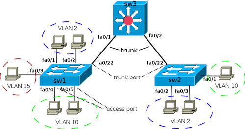
Создается VLAN с идентификатором 2 и задается для него имя следующим образом:
sw1(config)# vlan 2
sw1(config-vlan)# name test
Для удаления VLAN с идентификатором 2 используется:
sw1(config)# no vlan 2
Настройка Access портов
Для назначения коммутационного порта в VLAN нужно:
sw1(config)# interface fa0/1
sw1(config-if)# switchport mode access
sw1(config-if)# switchport access vlan 2
Диапазон коммутационных портов с fa0/4 до fa0/5 для VLAN 10 выполняется следующим образом:
sw1(config)# interface range fa0/4 — 5
sw1(config-if-range)# switchport mode access
sw1(config-if-range)# switchport access vlan 10
Чтобы просмотреть информацию о состоянии VLAN нужно:
sw1# show vlan brief
VLAN Name Status Ports
—- ——————————— ——— ——————————-
1 default active Fa0/6, Fa0/7, Fa0/8, Fa0/9,
Fa0/10, Fa0/11, Fa0/12, Fa0/13,
Fa0/14, Fa0/15, Fa0/16, Fa0/17,
Fa0/18, Fa0/19, Fa0/20, Fa0/21,
Fa0/22, Fa0/23, Fa0/24
2 test active Fa0/1, Fa0/2
10 VLAN0010 active Fa0/4, Fa0/5
15 VLAN0015 active Fa0/3
Настройка Trunk
Чтобы иметь возможность передачи трафика от нескольких VLAN посредством одного порта, его следует перевести в режим trunk. Конкретные режимы интерфейса (режим умолчания отличаются для разных моделей):
- auto – это автоматический режим порта, из которого переход в режим trunk возможен только в том случае, если порт на другом конце связи будет в режиме desirable или on;
- desirable – это режим, из которого порт может перейти к режиму trunk; в этом состоянии он периодично посылает DTP-кадры к другому порту, запрашивая его перейти в режим trunk; этот режим будет установлен, если другой порт находится в одном из трех режимов: auto, desirable или on;
- trunk – в этом случае порт постоянно пребывает в состоянии trunk, даже если другой порт не может поддерживать такой же режим;
- nonegotiate – это режим, с которого порт готов выполнить переход к режиму trunk; он не выполняет передачу DTP-кадров к другому порту. Этот режим предусмотрен для исключения конфликтных ситуаций с другим оборудованием (не бренда Cisco). В этом случае коммутационное устройство на другом конце связи должно быть настроено в ручном режиме для использования режима trunk.
По умолчанию для режима trunk разрешаются все VLAN. Чтобы через любой из поддерживаемых VLAN выполнялась передача данных, он должен быть активным. В активную фазу он переходит тогда, когда его создали на коммутаторе и один из его портов находится в режиме up/up.
VLAN создается на коммутаторе посредством команды vlan. Также он может формироваться автоматически на коммутаторе, когда к нему добавляются интерфейсы в режиме access.
В схеме, используемой с целью демонстрации настроек для коммутаторов sw1 и sw2, требуемые VLAN создадутся в момент добавления access-портов к соответствующим VLAN:
sw1(config)# interface fa0/3
sw1(config-if)# switchport mode access
sw1(config-if)# switchport access vlan 15
% Access VLAN does not exist. Creating vlan 15
Поскольку на коммутаторе sw3 отсутствуют access-порты, нужно создать все нужные VLAN:
sw3(config)# vlan 2,10,15
Чтобы автоматически создать VLAN на устройствах коммутации, можно применять протокол VTP.
Настройка статического Trunk
Чтобы создать статический trunk нужно:
sw1(config)# interface fa0/22
sw1(config-if)# switchport mode trunk
Модели коммутаторов, которые поддерживают ISL, после попытки перевода интерфейса в режим статического trunk могут выбрасывать следующую ошибку:
sw1(config-if)# switchport mode trunk
Command rejected: An interface whose trunk encapsulation is “Auto” can not be configured to “trunk” mode.
Ошибка генерируется потому, что процесс динамического определения инкапсуляции (выбор 802.1Q или ISL) может поддерживаться только с динамическим режимом trunk. Для настройки статического trunk нужно процедуру инкапсуляции также сделать статической. Этот тип коммутаторов предусматривает явное указание типа инкапсуляции для конкретного интерфейса:
sw1(config-if)# switchport trunk encapsulation dot1q
После этого повторно выполняется команда для настойки статического trunk – switchport mode trunk.
Динамическое создание Trunk
Dynamic Trunk Protocol (DTP) является проприетарным протоколом Cisco, обеспечивающим коммутационным устройствам возможность определять находится ли в состоянии поднятия trunk соседний коммутатор и какой протокол нужно задействовать ISL или 802.1Q. DTP включается по умолчанию. Он владеет следующими режимами интерфеса:
- auto – порт пребывает в автоматическом режиме и перейдет в trunk, когда на другом конце связи порт будет on или desirable; если на противоположных концах порты в режиме auto, trunk задействован не будет;
- desirable – из этого состояния порт может перейти к trunk; он периодически совершает посылку DTP-кадров к порту на другом конце; trunk будет установлен, если порт на другой стороне будет on, desirable, auto;
- nonegotiate – из этого состояния порт может перейти в trunk, DTP-кадры при этом не передаются; этот режим нужен чтобы предотвратить конфликт межу Cisco и не Cisco оборудованием.
Для перевода интерфейса в режим auto:
sw1(config-if)# switchport mode dynamic auto
Для перевода интерфейса в режим desirable:
sw1(config-if)# switchport mode dynamic desirable
Для перевода интерфейса в режим nonegotiate:
sw1(config-if)# switchport nonegotiate
Для проверки текущего режима DTP:
sw# show dtp interface
Разрешенные VLAN’
Изначально, по умолчанию, в trunk разрешаются все VLAN. Также можно создать ограничение перечня VLAN, которые можно передавать через тот или иной trunk. Чтобы указать список разрешенных VLAN для порта fa0/22 нужно выполнить:
sw1(config)# interface fa0/22
sw1(config-if)# switchport trunk allowed vlan 1-2,10,15
Чтобы добавить еще один разрешенный VLAN:
sw1(config)# interface fa0/22
sw1(config-if)# switchport trunk allowed vlan add 160
Для удаления VLAN из списка разрешенных:
sw1(config)# interface fa0/22
sw1(config-if)# switchport trunk allowed vlan remove 160
Native VLAN
Для стандарта 802.1Q используется понятие native VLAN. Информационный трафик для этого VLAN будет передаваться нетегированным. По умолчанию его роль выполняет VLAN 1, но можно указать и иной VLAN как native.
Для настройки VLAN 5 в native нужно:
sw1(config-if)# switchport trunk native vlan 5
После этого весь трафик, который принадлежит к VLAN 5, передастся посредством trunk-интерфейса нетегированным, а весь трафик, который пришел на trunk-интерфейс будет иметь маркировку, как принадлежащий к VLAN 5.
Настройка процесса маршрутизации между VLAN
Все настройки, касающиеся назначения портов VLAN, которые ранее выполнены для sw1, sw2, sw3 сохраняются. Для дальнейших настроек коммутатор sw3 используется как устройство 3-уровня.
Для этой схемы выполнять дополнительные настройки на маршрутизаторе не нужно. Коммутационная платформа будет реализовывать процесс маршрутизации между сетевыми конфигурациями разных VLAN, а к маршрутизатору будет отправляться трафик, который предназначен для других сетей.
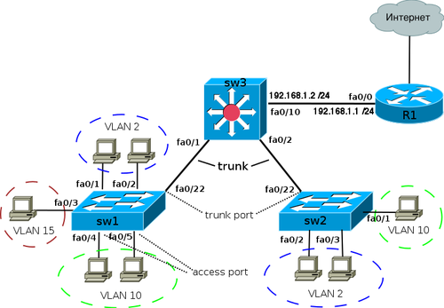
Настройки для коммутатора sw3:
VLAN / интерфейс 3го уровня IP-адрес
VLAN 2 10.0.2.1 /24
VLAN 10 10.0.10.1 /24
VLAN 15 10.0.15.1 /24
Fa 0/10 192.168.1.2 /24
Ч
тобы включить маршрутизацию на коммутаторе нужно:
sw3(config)# ip routing
Для определения адреса в VLAN, который будет использован, как маршрут по умолчанию для компьютерных систем во VLAN 2:
sw3(config)# interface Vlan2
sw3(config-if)# ip address 10.0.2.1 255.255.255.0
sw3(config-if)# no shutdown
Чтобы задать адрес для VLAN 10:
sw3(config)# interface Vlan10
sw3(config-if)# ip address 10.0.10.1 255.255.255.0
sw3(config-if)# no shutdown
Процесс перевода интерфейсов в режим 3-го уровня
Интерфейс fa0/10 соединяется с маршрутизатором и может переводиться в режим 3-го уровня. Для выполнения этой процедуры с заданием IP-адреса нужно:
sw3(config)#interface FastEthernet 0/10
sw3(config-if)# no switchport
sw3(config-if)# ip address 192.168.1.2 255.255.255.0
sw3(config-if)# no shutdown
R1 будет играть роль шлюза по умолчанию для конкретной сети. Информация, которая не предназначена для сети VLAN будет передаваться к R1.
Для настройки маршрута по умолчанию нужно выполнить:
sw3(config) ip route 0.0.0.0 0.0.0.0 192.168.1.1
Просмотр информации
Для просмотра информации о транке:
Port Mode Encapsulation Status Native vlan
Fa0/22 on 802.1q trunking 1
Port Vlans allowed on trunk
Fa0/22 1-2,10,15
Port Vlans allowed and active in management domain
Fa0/22 1-2,10,15
Port Vlans in spanning tree forwarding state and not pruned
Fa0/22 1-2,10,15
Чтобы выполнить просмотр информации о настройках интерфейса (trunk) нужно:
sw1# show interface fa0/22 switchport
Name: Fa0/22
Switchport: Enabled
Administrative Mode: trunk
Operational Mode: trunk
Administrative Trunking Encapsulation: dot1q
Operational Trunking Encapsulation: dot1q
Operational Dot1q Ethertype: 0x8100
Negotiation of Trunking: On
Access Mode VLAN: 1 (default)
Trunking Native Mode VLAN: 1 (VLAN_1)
Administrative Native VLAN tagging: enabled
Operational Native VLAN tagging: disabled
Voice VLAN: none
Administrative private-vlan host-association: none
Administrative private-vlan mapping: none
Operational private-vlan: none
Trunking VLANs Enabled: ALL
Pruning VLANs Enabled: 2-1001
Capture Mode Disabled
Capture VLANs Allowed: ALL
Чтобы выполнить просмотр информации о настройках интерфейса (access):
sw1# show interface fa0/3 switchport
Name: Fa0/3
Switchport: Enabled
Administrative Mode: static access
Operational Mode: static access
Administrative Trunking Encapsulation: negotiate
Operational Trunking Encapsulation: native
Operational Dot1q Ethertype: 0x8100
Negotiation of Trunking: Off
Access Mode VLAN: 15 (VLAN0015)
Trunking Native Mode VLAN: 1 (default)
Administrative Native VLAN tagging: enabled
Operational Native VLAN tagging: disabled
Voice VLAN: none
Administrative private-vlan host-association: none
Administrative private-vlan mapping: none
Operational private-vlan: none
Trunking VLANs Enabled: ALL
Pruning VLANs Enabled: 2-1001
Capture Mode Disabled
Capture VLANs Allowed: ALL
Просмотреть информацию о VLAN:
sw1# show vlan brief
VLAN Name Status Ports
—- ——————————— ——— ——————————-
1 default active Fa0/6, Fa0/7, Fa0/8, Fa0/9,
Fa0/10, Fa0/11, Fa0/12, Fa0/13,
Fa0/14, Fa0/15, Fa0/16, Fa0/17,
Fa0/18, Fa0/19, Fa0/20, Fa0/21,
Fa0/22, Fa0/23, Fa0/24
2 test active Fa0/1, Fa0/2
10 VLAN0010 active Fa0/4, Fa0/5
15 VLAN0015 active Fa0/3
Диапазоны VLAN
VLANs Диапазон Использование Передается VTP
0, 4095 Reserved Только для системного использования. —
1 Normal VLAN по умолчанию. Можно использовать, но нельзя удалить. Да
2-1001 Normal Для VLANов Ethernet. Можно создавать, удалять и использовать. Да
1002-1005 Normal Для FDDI и Token Ring. Нельзя удалить. Да
1006-4094 Extended Только для VLANов Ethernet. Версия 1 и 2 нет, версия 3 да
Примеры настройки
Базовая настройка VLAN (без настройки маршрутизации)
Для коммутатора sw3 маршрутизация между VLAN не настроена, поэтому хосты могут передаваться только в области одного VLAN.
Хосты для коммутатора sw1 в VLAN 2 могут взаимодействовать сами с собой и с хостами VLAN 2 коммутатора sw2. Правда они не могут взаимодействовать с хостами других VLAN коммутаторов sw1 и sw2.
Не все возможные настройки являются обязательными. К примеру, перечислять разрешенные VLAN для trunk не обязательно для его работы, но нужно выполнять явную настройку разрешенных VLAN.
Настройка trunk для sw1 и sw2 несколько отличается от sw3. Для него не нужно задавать инкапсуляцию trunk, так как sw3 может поддерживать только режим 802.1Q.
Конфигурация sw1 имеет вид:
!
interface FastEthernet0/1
switchport mode access
switchport access vlan 2
!
interface FastEthernet0/2
switchport mode access
switchport access vlan 2
!
interface FastEthernet0/3
switchport mode access
switchport access vlan 15
!
interface FastEthernet0/4
switchport mode access
switchport access vlan 10
!
interface FastEthernet0/5
switchport mode access
switchport access vlan 10
!
interface FastEthernet0/22
switchport trunk encapsulation dot1q
switchport mode trunk
switchport trunk allowed vlan 1,2,10,15
Конфигурация sw2 имеет вид:
!
interface FastEthernet0/1
switchport mode access
switchport access vlan 10
!
interface FastEthernet0/2
switchport mode access
switchport access vlan 2
!
interface FastEthernet0/3
switchport mode access
switchport access vlan 2
!
interface FastEthernet0/22
switchport trunk encapsulation dot1q
switchport mode trunk
switchport trunk allowed vlan 1,2,10
!
Конфигурация sw3 имеет вид:
!
vlan 2,10,15
!
interface FastEthernet0/1
switchport mode trunk
switchport trunk allowed vlan 1,2,10,15
!
interface FastEthernet0/2
switchport mode trunk
switchport trunk allowed vlan 1,2,10
!
Конфигурация с настройкой маршрутизации между VLAN
Для коммутатора sw3 выполнена настройка маршрутизации между VLAN, поэтому для этой схемы хосты могут обмениваться в области одного VLAN и между разными VLAN.
Процедуры настройки коммутаторов sw1 и sw2 аналогичные, как и прошлый раз. Добавлены только некоторые настройки для коммутатора sw3.

Конфигурация sw1 имеет вид:
!
interface FastEthernet0/1
switchport mode access
switchport access vlan 2
!
interface FastEthernet0/2
switchport mode access
switchport access vlan 2
!
interface FastEthernet0/3
switchport mode access
switchport access vlan 15
!
interface FastEthernet0/4
switchport mode access
switchport access vlan 10
!
interface FastEthernet0/5
switchport mode access
switchport access vlan 10
!
interface FastEthernet0/22
switchport trunk encapsulation dot1q
switchport mode trunk
switchport trunk allowed vlan 1,2,10,15
Конфигурация sw2 имеет вид:
!
interface FastEthernet0/1
switchport mode access
switchport access vlan 10
!
interface FastEthernet0/2
switchport mode access
switchport access vlan 2
!
interface FastEthernet0/3
switchport mode access
switchport access vlan 2
!
interface FastEthernet0/22
switchport trunk encapsulation dot1q
switchport mode trunk
switchport trunk allowed vlan 1,2,10
!
Конфигурация sw3 имеет вид:
!
ip routing
!
vlan 2,10,15
!
interface FastEthernet0/1
switchport mode trunk
switchport trunk allowed vlan 1,2,10,15
!
interface FastEthernet0/2
switchport mode trunk
switchport trunk allowed vlan 1,2,10
!
!
interface FastEthernet0/10
no switchport
ip address 192.168.1.2 255.255.255.0
!
!
interface Vlan2
ip address 10.0.2.1 255.255.255.0
!
interface Vlan10
ip address 10.0.10.1 255.255.255.0
!
interface Vlan15
ip address 10.0.15.1 255.255.255.0
!
!
ip route 0.0.0.0 0.0.0.0 192.168.1.1
!
Настройка VLAN для маршрутизаторов Cisco
Передача трафика между VLAN поддерживается за счет маршрутизатора. Чтобы он мог передать данные от одного VLAN к другому (между сетями) нужно, чтобы в каждой из сетей он имел свой интерфейс. Чтобы не выделять множество физических
интерфейсов в этом случае правильно создавать логические подинтерфейсы. Их создают на физических интерфейсах каждого VLAN. Порт коммутатора, который ведет к маршрутизатору, должен настраиваться как тегированный порт (trunk).
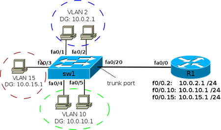
Схема, для которой процесс маршрутизации выполняется между VLAN на маршрутизаторе, называется «router on a stick». IP адреса шлюзов по умолчанию для VLAN:
VLAN IP-адрес
VLAN 2 10.0.2.1 /24
VLAN 10 10.0.10.1 /24
VLAN 15 10.0.15.1 /24
Для логических подинтерфейсов нужно указать, что на интерфейс будет приходить тегированный трафик, а также указать номер соответствующего VLAN. Выполнить эту процедуру можно соответствующей командой при настройке подинтерфейса:
R1(config-if)# encapsulation dot1q
Чтобы создать логический подинтерфейс для VLAN 2:
R1(config)# interface fa0/0.2
R1(config-subif)# encapsulation dot1q 2
R1(config-subif)# ip address 10.0.2.1 255.255.255.0
Чтобы создать логический подинтерфейс для VLAN 10:
R1(config)# interface fa0/0.10
R1(config-subif)# encapsulation dot1q 10
R1(config-subif)# ip address 10.0.10.1 255.255.255.0
Порт, ведущий от коммутатора к маршрутизатору должен настраиваться как статический trunk:
interface FastEthernet0/20
switchport trunk encapsulation dot1q
switchport mode trunk
Пример настройки
Конфигурационные файлы для первой схемы:
Для конфигурации sw1:
!
interface FastEthernet0/1
switchport mode access
switchport access vlan 2
!
interface FastEthernet0/2
switchport mode access
switchport access vlan 2
!
interface FastEthernet0/3
switchport mode access
switchport access vlan 15
!
interface FastEthernet0/4
switchport mode access
switchport access vlan 10
!
interface FastEthernet0/5
switchport mode access
switchport access vlan 10
!
interface FastEthernet0/20
switchport trunk encapsulation dot1q
switchport mode trunk
switchport trunk allowed vlan 2,10,15
!
Для конфигурации R1:
!
interface fa0/0.2
encapsulation dot1q 2
ip address 10.0.2.1 255.255.255.0
!
interface fa0/0.10
encapsulation dot1q 10
ip address 10.0.10.1 255.255.255.0
!
interface fa0/0.15
encapsulation dot1q 15
ip address 10.0.15.1 255.255.255.0
!
Настройка native VLAN
В режиме умолчания информационный трафик VLAN 1 передается нетегированым (VLAN 1 работает, как native). В этом случае для физического интерфейса маршрутизатора устанавливается адрес из сети VLAN 1.
Чтобы задать адрес для физического интерфейса:
R1(config)# interface fa0/0
R1(config-if)# ip address 10.0.1.1 255.255.255.0
Когда нужно создать подинтерфейс передачи нетегированного трафика, в нем указывается, что он принадлежит native VLAN. Как пример, для native VLAN 99:
R1(config)# interface fa0/0.99
R1(config-subif)# encapsulation dot1q 99 native
R1(config-subif)# ip address 10.0.99.1 255.255.255.0
Подборка инструкций по настройке VLAN на оборудовании Cisco. Примеры конфигурирования, описания возможных проблем, настройки и параметры.
Введение в виртуальные локальные сети VLAN
Если вы совсем новичок в теме, начните с этого видео,
посвященного технологии VLAN/
Пожалуй самое доступное объяснение:
Настройка VLAN в Cisco Packet Tracer
В данном уроке мы познакомимся с технологией VLAN, научимся
создавать их на коммутаторах, настраивать access и trunk порты.
Одно из лучших объяснений работы VLAN на оборудовании Cisco.
У кого бесконечный «Translating….» нажмите Ctrl + Shift +
6
Добавлять VLAN в транк только «switchport trunk allowed vlan add», чтобы
остальные не потерялись.
Учтите, что вы не пробросите VLAN без транка.
у коммутаторов есть два режима порта, это access, используется как правило для
конечных устройств (компы, принтеры, телефоны) и trunk — настраивается между
свичами. Access порт тегирует входящий трафик в коммутатор и растегирует
исходящий. Trunk порт не занимается тегированием, он просто прокидывает пакеты
основываясь на метках влана (тегах).
Настройка VLAN+NAT+DHCP
в Cisco Packet
Tracer
Еще одно подробное руководство по настройке VLAN на
оборудовании Cisco.
Маршрутизация между Cisco VLAN. Три варианта дизайна
В этом видео рассказывается о том, как работает
маршрутизация между виртуальными сетями Virtual LAN или Vlan, которая также
называется Inter vlan routing. Подробно
на уровне CCNA рассказывается какой дизайн сети выбрать, в чем преимущества и
недостатки каждого варианта дизайна.
Более чем подходит для подготовке к сертификационному тесту
CCNA Routing and Switching. Вам нужно разделить сеть на Vlan? Нужно настроить
взаимодействие. В видео рассматриваются три варианта построения маршрутизации
между Vlan. Обсуждаются плюсы и минусы каждого, а также применимость на
практике.
Как настроить VLAN
на коммутаторах Cisco Catalyst
2960
В этом видео показано на практике, как создать VLAN на
коммутаторе Cisco 2960, переключить порты в определенный VLAN, а также
передавать трафик между несколькими коммутаторами.
Настройка Native Vlan на Cisco
Native VLAN — это понятие в стандарте 802.1Q, которое
обозначает VLAN на коммутаторе, где все кадры идут без тэга, т.е. трафик
передается нетегированным. По умолчанию это VLAN 1. В некоторых моделях коммутаторов Сisco это можно изменить,
указав другой VLAN как native.
Если коммутатор получает нетегированные кадры на транковом
порту, он автоматически причисляет их к Native VLAN. И точно так же кадры,
генерируемые с не распределенных портов, при попадании в транк-порт
причисляются к Native VLAN.
Трафик, который принадлежит другим VLANам, тегируется с
указанием соответствующего VLAN ID внутри тега.
Пример настройки VLAN 5 как native на коммутаторе Cisco
sw1(config)# interface f0/10
sw1(config-if)# switchport trunk native vlan 5
Теперь весь трафик, принадлежащий VLAN 5 будет передаваться
через транковый интерфейс нетегированным, а весь пришедший на транковый
интерфейс нетегированный трафик будет промаркирован как принадлежащий VLAN’у 5
(по умолчанию VLAN 1).
Из соображений безопасности (например, для защиты от VLAN
Hopping) рекомендуется в транке выполнять тегирование даже для native VLAN.
Включить тегирование фреймов для native VLAN глобально можно с помощью команды
vlan dot1q tag native, просмотреть текущий статус тегирования можно используя
команду show vlan dot1q tag native.
Switch(config)#no vlan dot1q tag native
Switch#sho vlan dot1q tag native
dot1q native vlan tagging is disabled
Настройка Voice VLAN на Cisco
Большинство IP — телефонов, включая Cisco, имеют маленький
коммутатор на 3 порта внутри IP — телефона. Телефон подключается «в разрыв».
- Первый порт подключается к коммутатору;
- Второй порт подключается к компьютеру;
- Внутренний порт подключает сам телефон;
Как это все работает? Между коммутатором и телефоном у нас
есть так называемый «транк». Порт на телефоне, который подключается к
компьютеру, является портом доступа. Телефона передает весь трафик с компьютера
на коммутатор без каких — либо меток, непомеченным. Трафик с самого телефона
всегда будет помечаться, и в транке будут разрешены только два вышеупомянутых
VLANа.
Если вы уже знакомы с настройкой VLANов, то создание
голосового VLANа не составит для вас вообще никакого труда. Давайте настроим
порт на коммутаторе, где мы будем использовать VLANы 10 и 11.
Сначала мы создаем данные VLANы:
MERION-SW1(config)#vlan 10
MERION-SW1(config-vlan)#name DATA
MERION-SW1(config-vlan)#exit
MERION-SW1(config)#vlan 11
MERION-SW1(config-vlan)#name VOICE
MERION-SW1(config-vlan)#exit
Теперь настроим интерфейс:
MERION-SW1(config)#interface GigabitEthernet
0/1
MERION-SW1(config-if)#switchport mode access
MERION-SW1(config-if)#switchport access vlan 10
MERION-SW1(config-if)#switchport voice vlan 11
MERION-SW1(config-if)#exit
Мы переключили данный порт в режим доступа и настраиваем его
для VLAN 10. Команда switchport voice vlan сообщает коммутатору, чтобы он
использовал VLAN 11 как голосовой VLAN.
Для того, чтобы телефон понял, какой VLAN нужно
использовать, используются два протокола — Cisco Discovery Protocol (CDP) для
телефонов Cisco и Link Layer Discovery Protocol (LLDP) для телефонов от других
вендоров.
Справочная информация
Номера VLAN (VLAN ID)
Номера VLAN
(VLAN ID) могут быть в диапазоне от
1 до 4094:
-
1 — 1005
базовый диапазон (normal-range) - 1002 — 1005 зарезервированы для Token Ring и FDDI VLAN
-
1006
— 4094 расширенный диапазон (extended-range)
Параметры VLAN
При создании или изменении VLAN можно задать следующие параметры:
-
VLAN
ID — Номер VLAN -
VLAN
name (name) — Имя VLAN -
VLAN
type (media) — Тип VLAN (Ethernet, Fiber
Distributed Data Interface [FDDI], FDDI network entity title [NET], TrBRF, или
TrCRF, Token Ring, Token Ring-Net) -
VLAN
state (state) — Состояние VLAN (active или suspended) -
VLAN MTU
(mtu) — Максимальный
размер блока данных, который может быть передан на канальном уровне -
SAID
(said) — Security Association Identifier — идентификатор ассоциации безопасности (стандарт IEEE 802.10) -
Remote SPAN
(remote-span) — Создание VLAN для удаленного
мониторинга трафика (В дальнейшем в такой VLAN можно зеркалировать трафик с какого-нибудь порта, и передать
его через транк на другой коммутатор, в котором из этого VLAN трафик отправить на нужный порт с
подключенным снифером) -
Bridge
identification number для TrBRF VLAN (bridge) — Идентификатор номера моста для
функции TrBRF (Token Ring Bridge Relay Function). Цель функции — создание моста
из колец. -
Ring
number для FDDI и TrCRF VLAN (ring) — Номер кольца для типов VLAN FDDI и TrCRF
(Token Ring concentrator relay functions). TrCRF называют кольца, которые
включены в мост. -
Parent
VLAN number для TrCRF VLAN (parent) — Номер родительского VLAN для типа VLAN
FDDI или Token Ring -
Spanning
Tree Protocol (STP) type для TrCRF VLAN (stp type) — Тип протокола связующего
дерева (STP) для VLAN типа TrCRF -
Translational VLAN number
1 (tb-vlan1) — Номер VLAN для первичного преобразования
одного типа VLAN в
другой -
Translational VLAN number
2 (tb-vlan2) — Номер VLAN для вторичного преобразования
одного типа VLAN в
другой
Значения по умолчанию
| VLAN ID | 1 |
| VLAN name | VLANxxxx, где xxxx четыре цифры номера VLAN (Например: VLAN0003, VLAN0200 и т.д.) |
| SAID | 100000 плюс VLAN ID (Например: 100001 для VLAN 1, 100200 для VLAN 200 и т.д.) |
| VLAN MTU | 1500 |
| Translational VLAN number 1 | 0 |
| Translational VLAN number 2 | 0 |
| VLAN state | active |
| Remote SPAN | disabled |