Hello everyone! Today’s topic is, how to configure Telnet on your Cisco IOS devices. If you are not familiar with Telnet, read this WIKI page. By the end of this article, you will be confident enough to configure and troubleshoot Telnet related issues on Cisco routers and switches. So, let’s get started.

Definaion: Telnet is a network protocol, that allows you to gain remote access to your devices.
First of all, we will check our interface IPs by running show ip interface brief and choose an interface for telnet.
Cisco-RTR#show ip interface brief
Interface                  IP-Address      OK? Method Status                Protocol
GigabitEthernet0/0         10.1.1.50       YES NVRAM  up                    up
GigabitEthernet0/1         172.16.0.1      YES NVRAM  up                    up
GigabitEthernet0/2         172.16.1.1      YES NVRAM  up                    up
GigabitEthernet0/3         unassigned      YES NVRAM  administratively down down
GigabitEthernet0/4         unassigned      YES NVRAM  administratively down down
You can see interface gig0/0 to gig0/2 has IP addresses. And, we can telnet any IPs of this list, as long as we have the reachability. In this example, we will telnet on 10.1.1.50.
Telnet configuration will be in the bottom of the configuration file. You can use show run command to see the configuration. You also can use filter commands to go telnet configuration directly run using show run | section vty.
Cisco-RTR#show running-config | section vty
line vty 0 4
 login
 transport input none
VTY is a virtual port that helps to get Telnet or SSH access to the device. And, we will enable our telnet under line vty.
Before enabling telnet, you should know, we can enable telnet in two ways. In the first way, we will add a password for telnet. By this way, whenever someone tried to telnet to the device, they only need to use password, no username. Problem with this method is, you will not be able to identify who joined to the telnet session.
In the 2nd way, we can enable telnet for local users, where a telnet user need to have an account on the device.
Let’s configure telnet in first ways.
Method 1:
Cisco-RTR#configure terminal
Cisco-RTR(config)#line vty 0 4
Cisco-RTR(config-line)#transport input telnet
Cisco-RTR(config-line)#password cisco
Cisco-RTR(config-line)#login
Explanation:
transport input telnet: Enabling telnet.
password cisco: Setting the password for telnet. Password is cisco.
login: Allowing login
That’s it for 1st way. Now we can test our configuration. Let’s open a putty session and try to telnet 10.1.1.50.
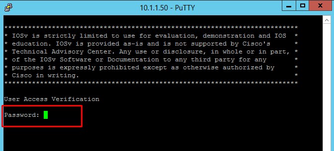
As expected, it is asking the password. After using password cisco and we are successfully logged in.
Now, let’s identify the problem with this method. We will run show users command.
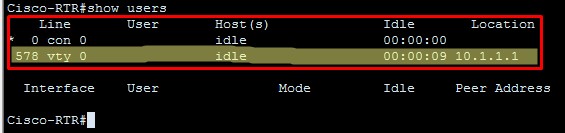
You can see, two people are logged in, one is using console and one is in vty. But, you will not be able to identify who logged in using vty.
Now, let’s move to the 2nd method.
Method 2:
Below are our configuration-
Cisco-RTR#configure terminal
Cisco-RTR(config)#line vty 0 4
Cisco-RTR(config-line)#transport input telnet
Cisco-RTR(config-line)#login local
Explanation:
transport input telnet: Enabling telnet.
login local: Allowing login using local credentials.
Now, we will test our telnet configuration by doing the telnet to the device. Let’s telnet to 10.1.1.50.
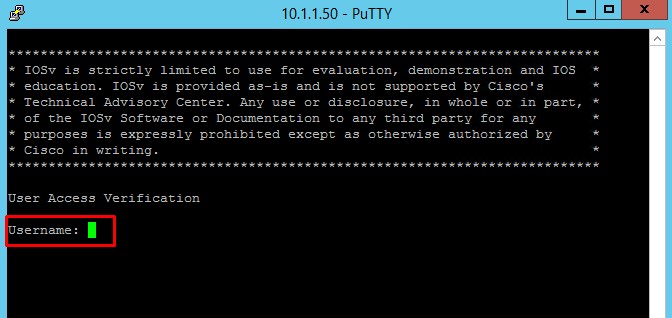
You can see it’s asking username, let’s use username rajib and then use its associated password.
Now, let’s check who is logged in to the device by running show users command.
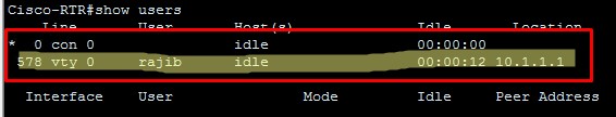
You can see, in vty session user rajib is logged in. Due to this, method 2 is more preferred than method 1.
I also want to refer you my another blog post for tacacs confiration. Link: How to configure TACACS+ on Cisco Routers and Switches.
So, this is how to configure Telnet on Cisco IOS routers and switches. Hope you will enjoy. Let me know if you have any questions about Telnet configuration.
Configuring Dial-In Terminal Services
This chapter describes how to configure support for asynchronous character stream calls running Telnet, rlogin, local-area transport (LAT), XRemote, or TN3270. It includes the following main sections:
- Dial-In Terminal Service Overview
- Configuring Telnet and rlogin
- Telnet and rlogin Configuration Task List
- Using Cisco DialOut for Telnet Connections
- Connecting a VMS Host Using LAT
- LAT Configuration Task List
- Monitoring and Maintaining LAT Connections
- LAT Configuration and Connection Examples
- Configuring TN3270
- TN3270 Configuration Task List
- TN3270 Configuration and Connection Examples
- Configuring XRemote
- XRemote Configuration Task List
- XRemote Configuration and Connection Examples
For a complete description of the dial-in terminal services commands in this chapter, refer to the Cisco IOS Terminal Services Command Reference. To locate documentation of other commands that appear in this chapter, use the command reference master index or search online.
Dial-In Terminal Service Overview
Inbound asynchronous character stream calls are routed to virtual terminal lines and virtual asynchronous interfaces, which are used to terminate incoming character steams that do not share a physical connection with the access server or router (such as a physical interface). A virtual asynchronous interface is the place where inbound Telnet, LAT, V.120, TN3270, and packet assembler/disassembler (PAD) calls or sessions terminate on the router. Virtual terminal lines are used for attaching to the router in a nonphysical way.
Configuring support for terminal service connections means enabling network devices running the same protocol to connect across a LAN or WAN through network and terminal-emulation software.
The following sections describe how to configure these supported dial-in terminal services:
- Configuring Telnet and rlogin—Of all protocol suites, TCP/IP is the most widely implemented on networks of all media types. TCP/IP is the current standard for internetworking and is supported by most computer vendors, including all UNIX-based workstation manufacturers. TCP/IP includes Telnet and rlogin.
- Connecting a VMS Host Using LAT—The proprietary LAT terminal connection protocol from Digital Equipment Corporation used with Digital minicomputers.
- Configuring TN3270—IBM 3278 terminal emulation provides TN3270-based connectivity to IBM hosts over serial lines.
- Configuring XRemote—The X Window Systems terminal protocol from Network Control Devices, Inc., provides network functionality to remote X terminals.
Each section provides examples of how to configure and connect to a terminal service.
Configuring Telnet and rlogin
Telnet and rlogin are protocols that enable TCP/IP connections to a host. Telnet, a virtual terminal protocol that is part of the TCP/IP protocol suite, is the more widely used protocol. The rlogin protocol is a remote login service developed for the Berkeley Software Distribution (BSD) UNIX system. It provides better control and output suppression than Telnet, but can only be used when the host (typically, a UNIX system) supports rlogin. The Cisco IOS implementation of rlogin does not subscribe to the rlogin “trusted host” model. That is, a user cannot automatically log in to a UNIX system from the router, but must provide a user ID and a password for each connection.
Telnet allows a user at one site to establish a TCP connection to a login server at another site, then passes the keystrokes from one system to the other. Telnet can accept either an IP address or a domain name as the remote system address. In short, Telnet offers three main services:
- Network virtual terminal connection
- Option negotiation
- Symmetric connection
The Cisco implementation of Telnet supports the following Telnet options:
- Remote echo
- Binary transmission
- Suppress go ahead
- Timing mark
- Terminal type
- Send location
- Terminal speed
- Remote flow control
- X display location
Telnet and rlogin Configuration Task List
To configure Telnet and rlogin, perform the tasks in the following sections:
- Configuring Telnet and UNIX rlogin (Required for Service)
- Making Telnet and UNIX rlogin Connections (Required for Making Connections)
- Using UNIX Style Syntax for rlogin Connections (Optional)
The section “Monitoring TCP/IP Connections” later in this chapter provides tasks for maintaining TCP/IP connections.
Configuring Telnet and UNIX rlogin
To configure support for Telnet or rlogin calls, use the following commands beginning in line configuration mode.
|
|
|
|---|---|
|
|
Negotiates speeds on reverse Telnet lines. |
|
|
Causes Telnet to refuse to negotiate full-duplex, remote echo requests on incoming connections. |
|
|
Sets line to send a RETURN (CR) as a CR followed by a NULL instead of a CR followed by a LINE FEED (LF). |
|
|
Sets the line to send a Telnet Synchronize signal when it receives a Telnet BREAK signal. |
|
|
Sets the line to cause the system to generate a hardware BREAK signal on the EIA/TIA-232 line that is associated with a reverse Telnet connection when a Telnet Interrupt-Process command is received on that connection. |
|
Router(config)# ip tcp chunk-size number |
In global configuration mode, optimizes the line by setting the number of characters output before the interrupt executes. |
|
|
In interface configuration mode, assigns an IP address to the service provided on a TCP port. |
|
Router(config)# busy-message hostname d message d |
In global configuration mode, defines a message that the router displays whenever a Telnet or rlogin connection to the specified host fails. |
|
Router(config)# login-string hostname d message [ % sec p ] [ % sec w ] [ %b ] d [ %m ] d |
In global configuration mode, defines a message that the router displays whenever a Telnet or rlogin connection to the specified host succeeds. |
|
|
Sets up a line to notify a user that has multiple, concurrent Telnet connections when output is pending on a connection other than the current one. |
|
|
Defines a “line-in-use” message to indicate that the line is currently busy. |
The telnet speed command sets the line speed to match line speeds on remote systems in reverse Telnet, on host machines hooked up to an access server or router to access the network, or on a group of console lines hooked up to the access server or router when disparate line speeds are in use at the local and remote ends of the connection. Line speed negotiation adheres to the Remote Flow Control option, defined in RFC 1080.
The telnet refuse-negotiations command suppresses negotiation of the Telnet Remote Echo and Suppress Go Ahead options.
The telnet transparent command is useful for coping with different interpretations of end-of-line handling in the Telnet protocol specification.
The telnet sync-on-break command sets the line to cause a reverse Telnet line to send a Telnet Synchronize signal when it receives a Telnet BREAK signal. The Telnet Synchronize signal clears the data path, but the line still interprets incoming commands.
Enter the telnet break-on-ip command to control the translation of Telnet Interrupt-Process commands into X.25 BREAK indications, and to work around the following situations:
- Several user Telnet programs send a Telnet Interrupt-Process command, but cannot send a Telnet BREAK signal.
- Some Telnet programs implement a BREAK signal that sends a Telnet Interrupt-Process command.
- Some EIA/TIA-232 hardware devices use a hardware BREAK signal for various purposes.
When the telnet break-on-ip command is used with a correctly operating host, Cisco IOS software implements the Telnet Synchronize and Abort Output signals, which can stop output within one packet worth of data from the time the user types the interrupt character. Enter the ip tcp chunk-size command to configure a faster response to user interrupt characters. Changing the number of characters output, or chunk size, affects neither the size of the packet used nor the TCP window size, either of which would cause serious efficiency problems for the remote host and for the access server or router. Instead, the system software checks the Telnet status after the number of characters specified, causing only a relatively minor performance loss.
Use the ip alias command to configure connections to an IP address to act identically to connections made to the primary IP address of the server on the TCP port. A user trying to connect is connected to the first free line in a rotary group using the Telnet protocol.
With the login-string command options, you can set a pause, prevent a user from issuing commands during a pause, send a BREAK character, and use a percent sign (%) in the login string. The busy-message command and login-string command are only useful with two-step protocol translation sessions. For more information about protocol translation, see the chapter “Configuring Protocol Translation and Virtual Asynchronous Devices” in this publication.
For actual sample configurations on how to configure Telnet and rlogin, see the section “Telnet and rlogin Examples” later in this chapter.
Making Telnet and UNIX rlogin Connections
To provide Telnet and rlogin connection capabilities, use the following commands in EXEC mode:
|
|
|
|
|---|---|---|
|
Step 1 |
or |
Logs in to a host that supports Telnet. Refer to the descriptions for the connect and telnet commands in the Cisco IOS Terminal Services Command Reference, for a list of supported keywords.1 |
|
Step 2 |
|
Displays a list of available hosts. |
|
Step 3 |
|
Displays the status of all TCP connections. |
|
Step 4 |
Ctrl^ |
Logs out of the host by entering the default escape sequence.2 |
|
Step 5 |
Choose from the following list of escape sequences, according to your task: Press Ctrl^ b if your task is to break. |
Logs out of the host by entering a special escape sequence. 2 These special Telnet sequences map generic terminal control functions to operating system-specific functions. |
|
Step 6 |
Ctrl^ ? |
Lists the available Telnet commands at any time during the active Telnet session. 2 |
|
Step 7 |
exit or logout |
Exits a Telnet or rlogin session. |
1.Cisco IOS software provides a robust collection of connection options. The options allow for enhanced sessions allowing, for example, encrypted sessions, Kerberos login, and File Transfer Protocol and World Wide Web connections. Additionally, it is possible to suppress system messages, including IP addresses and server names, displayed during session connection and disconnection. This function allows transparent TCP connections and can be useful when an asynchronous tunnel connection is being made.
2.Press and hold the Ctrl and Shift keys while pressing the 6 key. You can enter the command character as you hold down the Ctrl key or with Ctrl released; you can enter the command characters as either uppercase or lowercase letters.
With the Cisco IOS implementation of TCP/IP, you are not required to enter the connect or telnet commands to establish a Telnet connection. You can just enter the learned host name as long as the host name is different from a command word for the router. Telnet must be the default (you can make it the default with the transport preferred command). Use the show hosts EXEC command to display a list of the available hosts. Use the show tcp EXEC command to display the status of all TCP connections. The Cisco IOS software assigns a logical name to each connection, and several commands use these names to identify connections. The logical name is the same as the host name, unless that name is already in use or you change the connection name with the name-connection EXEC command. If the name is already in use, the Cisco IOS software assigns a null name to the connection. For an example of making a Telnet connection, see the section “Telnet and rlogin Examples” later in this chapter.
After you enter the rlogin command, you can have several concurrent rlogin connections open and switch between them. To open a new connection, exit the current connection by entering the escape sequence (Ctrl-Shift-6 then x [ Ctrl^x ] by default) to return to the system command prompt, then open a new connection. For an example of making an rlogin connection or switching between connections, see the sections “rlogin Connection Example” or “Switch Between Telnet and rlogin Sessions Example” later in this chapter.

Note![]() We recommend that you use Encrypted Kerberized Telnet whenever you establish a Telnet session to a router or access server, which protects the integrity of the device. For information about Encrypted Kerberized Telnet, refer to Cisco IOS Security Configuration Guide.
We recommend that you use Encrypted Kerberized Telnet whenever you establish a Telnet session to a router or access server, which protects the integrity of the device. For information about Encrypted Kerberized Telnet, refer to Cisco IOS Security Configuration Guide.
Using UNIX Style Syntax for rlogin Connections
The rlogin command supports the standard BSD UNIX -l option. Before this addition was introduced, the rlogin command allowed remote users to log in using the /user username option, which was not compatible with the standard UNIX rlogin -l username option.
This feature is supported on all of Cisco TCP/IP-enabled routers and access servers.
To set up this UNIX feature, use one of the following the following commands in EXEC mode:
|
|
|
|---|---|
|
Router# rlogin hostname |
Enters the name of the host to which you are connecting. |
|
Router# rlogin hostname [ -l hostname] [ /user hostname] |
Enters the user name. |
|
Router# rlogin hostname [ -l hostname] [ /user hostname] debug |
(Optional) Enters the debug mode to troubleshoot the connection from the remote site to the host. |
|
Router# rlogin hostname [ -l hostname] [ /user hostname] /quiet |
(Optional) Enters the /quiet keyword to make a transparent connection from the remote site to the host. |
When you are done with the UNIX session, use the exit command to end it.
Monitoring TCP/IP Connections
To display the status of a TCP connection or view a summary of the TCP connection endpoints in the system, use the following commands in user EXEC mode:
|
|
|
|---|---|
|
|
Displays the status of a TCP connection. |
|
|
Displays a summary of the TCP connection endpoints in the system. |
Telnet and rlogin Examples
This section provides the following examples:
- Telnet Connection Example
- Telnet Connection Without and With Messages Suppressed Example
- rlogin Connection Example
- rlogin UNIX-Style Syntax Example
- Switch Between Telnet and rlogin Sessions Example
- List Supported Telnet Commands Example
Telnet Connection Example
The following example establishes a telnet connection to a host named server1 and specifies vt100 as the terminal type for the session:
Router> telnet server1 /terminal-type vt100
The following example connects to a host with logical name host1:
Telnet Connection Without and With Messages Suppressed Example
The following examples show how to suppress the onscreen messages displayed during login and logout of a Telnet session.
The following example shows the messages displayed when a connection is made without using the optional /quiet keyword with the telnet EXEC command to suppress messages from the operating system:
The following example shows the limited messages displayed when connection is made using the optional /quiet keyword:
The /quiet keyword is useful for making transparent connections during asynchronous tunnel connections. The keyword can be used with any of the EXEC connection commands— connect, telnet, and rlogin.
Note![]() The Cisco IOS software offers the ip telnet quiet global configuration command, which also suppresses onscreen messages during Telnet connections. The ip telnet quiet command is set globally, and is useful to Internet service providers that want to permanently suppress onscreen system connection messages that often include information such as server names and IP addresses. Refer to the Cisco IOS Dial Technologies Command Reference, for more information about the ip telnet quiet command.
The Cisco IOS software offers the ip telnet quiet global configuration command, which also suppresses onscreen messages during Telnet connections. The ip telnet quiet command is set globally, and is useful to Internet service providers that want to permanently suppress onscreen system connection messages that often include information such as server names and IP addresses. Refer to the Cisco IOS Dial Technologies Command Reference, for more information about the ip telnet quiet command.
rlogin Connection Example
The following example makes an rlogin connection to a host at address 172.31.21.2 and enables the message mode for debugging:
rlogin UNIX-Style Syntax Example
The following example illustrates how a user named jsmith can use the rlogin ? help command and the debug mode to establish and troubleshoot a remote connection to the host named Alviso:
Switch Between Telnet and rlogin Sessions Example
You can switch between sessions by escaping one session and resuming a previously opened session. The following example shows how to escape out of a connection to the host named host1 and to resume connection 2. You escape out of the current session and return to the EXEC prompt by entering the command sequence Ctrl-Shift-6 then x. Resume the connection with the resume command.
You can omit the command name and simply enter the connection number to resume that connection. The following example illustrates how to resume connection 3:
To list all the open sessions associated with the current terminal line, use the where command.
List Supported Telnet Commands Example
At any time during an active Telnet session, you can list the Telnet commands by pressing the escape sequence keys (by default Ctrl-Shift-6) followed by a question mark at the system prompt:
A sample of this list follows:
Note![]() In screen output examples that show two caret (^^) symbols together, the first caret represents the Ctrl key and the second caret represents the keystroke sequence Shift-6. The double caret combination (^^) means hold down the Ctrl key while you press the Shift and the 6 keys.
In screen output examples that show two caret (^^) symbols together, the first caret represents the Ctrl key and the second caret represents the keystroke sequence Shift-6. The double caret combination (^^) means hold down the Ctrl key while you press the Shift and the 6 keys.
Using Cisco DialOut for Telnet Connections
The Cisco DialOut feature enables users on a workstation operating Windows to send faxes or connect to service provider services outside the LAN by using modems attached or internal to a network access server. The Cisco DialOut feature extends the functionality of Telnet by enabling users to control the activity of these modems from their desktop computers using standard communications software.
The Cisco DialOut feature has two components:
- Telnet Extensions for Dialout—Network access server component
- The DialOut Utility—Client/desktop component
Both components are required and neither can function as a stand-alone feature.
The Telnet Extensions for Dialout component uses reverse Telnet to access modems attached to the network access server. This component enables the network access server to interface with the client/desktop component of the Cisco DialOut feature and to return Carrier Detect signals to the communications software so that the software can determine when to start dialing a particular number.
Telnet extensions allow the communications software running on the desktop computer of the client to control modem settings such as baud rate, parity, bit size, and stop bits.
To enable this feature, you only need to configure the access server or router for reverse Telnet and configure the appropriate lines to send and receive calls.
The client/desktop component of Cisco DialOut feature must be installed on the client workstation before this feature can be used. For information about installing and using the client/desktop component of the Cisco Dial-Out feature, and configuring the access server, see the DialOut Utility User Guide Cisco publication at Cisco.com.
Configuring Stream TCP
Stream TCP connections, or raw TCP or TCP-Clear connections as they are sometimes called, are used to transport a stream of 8-bit characters as-is over an IP network, between a TCP client and TCP server system. This method is used to transport legacy asynchronous application data through an IP network, for example, with a Point-of-Sale (PoS) terminal connecting to an application server.
To establish a Stream TCP connection from an EXEC session, use the /stream keyword with the telnet command. You will also generally want to configure the line to provide for data transparency. See the following procedure for the steps to do this.
Stream TCP Autocommand Procedure
In the following procedure, a line is configured so that any connection into it is automatically connected using Stream TCP to the application server at the specified IP address and TCP port (IP address 10.1.2.3 and TCP port 4321 in the examples).
Step 1![]() Configure the line for data transparency using the following configuration as an example:
Configure the line for data transparency using the following configuration as an example:
Step 2![]() Configure the autocommand:
Configure the autocommand:
Step 3![]() Configure the telnet-faststream option (this is an optional step). On platforms that support this feature such as the Cisco AS5800 access servers, you may want to configure the telnet-faststream autocommand option to provide for Stream TCP performance enhancements. An example of how this option can be entered follows:
Configure the telnet-faststream option (this is an optional step). On platforms that support this feature such as the Cisco AS5800 access servers, you may want to configure the telnet-faststream autocommand option to provide for Stream TCP performance enhancements. An example of how this option can be entered follows:
Connecting a VMS Host Using LAT
Connection to a VMS host is slightly different if you are connecting to a VMS host running VMS Version 5.4 or earlier than when connecting to a VMS host running VMS Version 5.5 or later software.
VMS Version 5.4 or Earlier System
If a host-initiated connection is received that specifies a destination port number that corresponds to a virtual port on the router, a virtual EXEC process will be created to allow the user to log in. This process can be used, in conjunction with the Digital set host/dte command on VMS, to connect to a router named router1 from a VMS host node, as shown in the following example:
VMS Version 5.5 or Later System
To connect to a VMS host running VMS Version 5.5 or later software, you must turn on the outgoing connections of the VMS LAT hosts and use the Digital set host/lat command, as shown in the following example:
Port Names When Configuring a LAT Printer
When you configure a LAT printer, the LAT port name is the line number without a “TTY” designation on the show lines command output. For example, if you configure terminal line 10 (named ABLE) to be a LAT printer port, you must use the OpenVMS command to associate an arbitrary LAT device to the LAT port name, as follows:
The LAT port name is the line number without the “TTY,” regardless of whether the format of the TTY line number is decimal or octal.
Additional LAT Capability
The Cisco IOS software fully supports the LAT protocol suite, and provides the following features:
- High-speed buffering—Handles a full screen of data (2000 characters) at full speed without requiring additional flow control.
- Protocol transparency—Handles connections transparently. The user needs no protocol information to establish a connection.
- Simplified configuration management—Uses logical names for LAT group codes to simplify the network structure.
- Maintenance Operation Protocol (MOP)—Supports the Digital protocol to support the request ID message, periodic system ID messages, and the remote console carrier functions for Ethernet interfaces.
LAT Configuration Task List
The Cisco IOS software LAT protocol is supplied with a default configuration and does not require additional configuration for you to use it.
To enable LAT and customize LAT for your particular network environment, perform the tasks described in the following sections:
- Configuring Basic LAT Services (Required for Service)
- Enabling Inbound Services (As Required)
- Controlling Service Announcements and Service Solicitation (As Required)
- Configuring Traffic Timers (As Required)
- Optimizing Performance (As Required)
- Defining LAT Access Lists (As Required)
- Enabling Remote LAT Modification (As Required)
- Making LAT Connections (Required for Making Connections)
The section “Monitoring and Maintaining LAT Connections” later in this chapter provides tips for maintaining LAT connections. The section “LAT Configuration and Connection Examples” later in this chapter provides LAT configuration examples.
Configuring Basic LAT Services
To enable basic LAT services, use the following commands beginning in interface configuration mode:
|
|
|
|
|---|---|---|
|
Step 1 |
|
Enables the LAT protocol. LAT is disabled by default. |
|
Step 2 |
|
Gives the router a LAT node name that is different than the host name. |
|
Step 3 |
|
(Optional) Defines the group list for an outgoing connection on a specified line. |
|
Step 4 |
Router(config)# l at group-list groupname { number | range | all } [ enabled | disabled ] |
(Optional) Specifies logical names for group lists. |
|
Step 5 |
Router(config)# lat service-group { groupname | number | range | all } [ enabled | disabled } |
(Optional) Specifies groups to be advertised. |
|
Step 6 |
|
(Optional) Enables remote LAT modification of line characteristics. |
Use the lat out-group command to define the list of services to which a user can connect. You create this list by defining the group code lists used for connections from specific lines. You can limit the connection choices for an individual line by defining the group code lists for an outgoing connection. When a user initiates a connection with a LAT host, the line of the user must share a common group number with the remote LAT host before a connection can be made.
Use the lat group-list command to specify a name for group lists to simplify the task of entering individual group codes. A name makes it easier to refer to a long list of group code numbers. To display the defined groups, use the show lat groups command.
Use the lat service-group command to specify a group code mask to use when advertising all services for a node. You can enter more than one group code by listing the numbers. You can also enter both a group code name and group codes.
Use the lat remote-modification line configuration command to configure a LAT line so that a remote LAT node can change the operating characteristics of the line.
Enabling Inbound Services
Just as LAT services are offered by host computers, they also can be offered by access servers and routers, because they implement both the host and server portions of the LAT protocol. This capability allows connections from either hosts or local access servers or routers. A host connected to a local device is called a host-initiated connection.
The tasks described in this section define support for host-initiated connections. This support includes refining the list of services that the router will support. An incoming session can be to either a port or a service. The port name is the terminal line number, as reported by the show users all EXEC command.
To enable inbound services, use the following commands in global configuration mode as needed:
|
|
|
|---|---|
|
Router(config)# lat service service-name password password |
Sets the LAT password for a service. |
|
Router(config)# lat service service-name ident identification |
Sets the LAT service ID for a specific service. |
|
Router(config)# lat service service-name rating static-rating |
Specifies a static service rating for a specific service. |
|
Router(config)# lat service service-name rotary group |
Configures a LAT rotary group. |
|
Router(config)# lat service service-name autocommand command |
Associates a command with a specific service for auto-execution. |
|
Router(config)# lat service service-name enabled |
Enables inbound connections to a specific service. |
Use the show lat advertised EXEC command to display LAT services offered to other systems on the network.
A service must be specifically enabled, but not all of the attributes in the previous task table are necessary in a particular environment.
Controlling Service Announcements and Service Solicitation
You can configure the Cisco IOS software to support the service responder feature that is part of the LAT Version 5.2 specification.
Specifically, the DECserver90L+, which has less memory than other Digital servers, does not maintain a cache of learned services. Instead, the DECserver90L+ solicits information about services as they are needed.
LAT Version 5.2 nodes can respond for themselves, but LAT Version 5.1 nodes, for example, VMS Version 5.4 or earlier nodes, cannot. Instead, a LAT Version 5.2 node configured as a service responder can respond in proxy for those LAT Version 5.1 nodes.
The Cisco IOS software can be configured as a LAT service responder. Of course, if all your nodes are LAT Version 5.2 nodes, you need not enable the service responder features.
To control service announcements and service solicitations, use the following commands in global configuration mode:
|
|
|
|
|---|---|---|
|
Step 1 |
Router(config)# lat service-responder |
Enables a proxy node to respond to solicit-information multicast messages. |
|
Step 2 |
Router(config)# no lat service-announcements |
Disables periodic broadcasts of service advertisements. |
|
Step 3 |
Router(config)# lat service-timer interval |
Adjusts the time between service announcements. |
Use the lat service-responder command to configure the Cisco IOS software to respond to solicit information requests addressed to LAT Version 5.1 nodes. This function allows nodes that do not cache service advertisements to interoperate with nodes that do not respond to solicit requests. Figure 1 shows how a router can act as a proxy for LAT servers.
Figure 1 Router as Proxy for LAT Server

The DECserver90L+ broadcasts a solicit information request in search of service for address Stella. The VMS host, Stella, is unable to respond to the request because it is running LAT Version 5.1. The access server is running LAT Version 5.2 with service responder enabled and informs the DECserver90L+ of the address for Stella.
Use the no lat service-announcements command to disable periodic broadcasts of service announcements. If service announcements are enabled, the LAT node will periodically broadcast service advertisements. If service announcements are disabled, the LAT node will not send service announcements, so a remote node requiring connection to the local node must use solicit-information messages to look up node information. Disable service announcements only if all of the nodes on the LAN support the service responder feature.
Use the lat service-timer command to adjust the time between LAT service advertisements for services offered. This command is useful in large networks with many LAT services and limited bandwidth.
Configuring Traffic Timers
You can customize the environment for sending LAT messages. The Cisco IOS implementation of LAT allows you to set the following features:
- The number of retransmissions before declaring a system unreachable
- The interval of time LAT waits before sending a keepalive message on an idle connection
- The interval of time LAT waits between transmission of messages
These features affect all LAT connection types.
To enable these features, use the following commands in global configuration mode:
|
|
|
|
|---|---|---|
|
Step 1 |
Router(config)# lat retransmit-limit number |
Sets the message retransmit limit. |
|
Step 2 |
Router(config)# lat ka-timer seconds |
Sets the keepalive timer. |
|
Step 3 |
Router(config)# lat vc-timer milliseconds |
Sets the virtual circuit timer. |
Optimizing Performance
To optimize performance for your LAT environment, use the following commands beginning in global configuration mode:
|
|
|
|
|---|---|---|
|
Step 1 |
Router(config)# lat vc-sessions number |
Sets the maximum number of sessions on a LAT virtual circuit. The maximum (and default) number of sessions is 255. |
|
Step 2 |
Router(config)# lat host-buffers receive-buffers |
Allows a LAT host node to receive more than one message at a time. |
|
Step 3 |
Router(config)# lat server-buffers receive-buffers |
Allows a LAT server node to receive more than one message at a time. |
|
Step 4 |
Router(config)# lat host-delay number |
Specifies the delay acknowledgment for incoming LAT slave connections, where number is milliseconds. |
Use the lat host-buffers command to set the number of messages received by a host at one time. Increasing this number can enhance performance. Before LAT Version 5.2, LAT allowed only one outstanding message at one time on a virtual circuit. This restriction could limit the performance of the Cisco IOS software when it processed a large number of messages because only one Ethernet packet of data could be in transit at a time. During virtual circuit startup, each side communicates to the other how many outstanding messages it is willing to accept.
Use the lat server-buffers command to set the number of messages received by a server at one time. Increasing this number can enhance performance. Before LAT Version 5.2, LAT allowed only one outstanding message at one time on a virtual circuit. This restriction could limit the performance of Cisco IOS software when it processed a large number of messages because only one Ethernet packet of data could be in transit at a time. With LAT Version 5.2, nodes can indicate that they are willing to receive more than one message at a time. During virtual circuit startup, each side communicates to the other how many outstanding messages it is willing to accept.
Use the lat host-delay command to set a user-defined delay for the acknowledgment for incoming LAT slave connections. This command is useful in situations where you need to control the delay. For example, if data is being transferred between a Digital server (using LAT) and a UNIX host (using Telnet) via a protocol translator, the protocol translator imposes the LAT delay on the Telnet and the LAT service, where Telnet may time out due to the LAT restriction.
Defining LAT Access Lists
Because LAT groups were not intended to implement security or access control, the Cisco IOS software supports access lists to provide these functions. An access list is a sequential collection of permit and deny conditions that serve to restrict access to or from LAT nodes on a specific terminal line. Each access list statement defines a permit or deny condition and a matching criterion for the node name.
When a LAT connection is attempted (either incoming or outgoing), the node name of the destination service (not the service name) is compared against the regular expression. If they match, the connection is permitted or denied as specified.
To define access lists and conditions, use the following commands beginning in global configuration mode:
|
|
|
|
|---|---|---|
|
Step 1 |
Router# configure terminal |
Enters global configuration mode. |
|
Step 2 |
Router(config)# lat access-list number { permit | deny } node-name |
Specifies an access condition. |
|
Step 3 |
Router(config)# line line-number |
Enters line configuration mode. |
|
Step 4 |
|
Restricts incoming and outgoing connections between a particular terminal line or group of lines and the node names in an access list. |
Enabling Remote LAT Modification
You can configure a LAT line so that a remote LAT node can change the operating characteristics of the line. To enable remote LAT modification, use the following command in line configuration mode:
|
|
|
|---|---|
|
|
Enables remote LAT modification of line characteristics. |
Making LAT Connections
The LAT protocol is most often used to connect routers to Digital hosts. LAT is a Digital-proprietary protocol, and the Cisco IOS software uses LAT technology licensed from Digital to allow the following LAT services:
- Make a LAT connection
- Define a group code list for outgoing LAT connections
- Switch between LAT sessions
- Use Digital commands on the server
- Exit a LAT session
For actual LAT connection examples, see the section “LAT Configuration and Connection Examples” later in this chapter.
To enable specific LAT connections or services, use the following commands in EXEC mode:
|
|
|
|
|---|---|---|
|
Step 1 |
|
Connects to a LAT host.3 |
|
Step 2 |
|
(Optional) Defines a temporary list of services to which you or another user can connect by defining the group code lists used for connections from specific lines. |
|
Step 3 |
|
(Optional) Lists available LAT services. |
|
Step 4 |
|
(Optional) Lists the subset of Digital commands that the Cisco IOS software supports. |
3.You can quit the connection by pressing Ctrl-C or complete the connection by entering the password for a given service.
You can also set your preferred connection protocol to any available connection protocol supported in the Cisco IOS software. Your preferred connection protocol is also referred to in the Cisco IOS software as a “preferred transport type.” If your preferred connection protocol is set to lat, you can use the connect command in place of the lat command. To configure a preferred connection protocol, use the transport preferred command. When your preferred connection protocol is set to none or to another protocol, you must use the lat command to connect to a LAT host.
To specify a temporary list of services to which you or another user can connect, you must define the group code lists used for connections from specific lines. You limit the connection choices for an individual line by defining the group code lists for an outgoing connection. To define a group code list, use the terminal lat out-group command. When a user initiates a connection with a LAT host, the line of the user must share a common group number with the remote LAT host before a connection can be made. The group code range must be a subset of the configured group code range of the line.
You can have several concurrent LAT sessions open and switch between them. To open a subsequent session, first enter the escape sequence (Ctrl-Shift-6 then x [Ctrl^x] by default) to suspend the current session. Then open a new session. To list the available LAT services, enter the show lat services EXEC command.
When you are done with the LAT session, use the exit command to end it, then terminate the active LAT session by entering the Ctrl-C key sequence.
Monitoring and Maintaining LAT Connections
To monitor and maintain LAT connections, use the following commands in EXEC mode as needed:
|
|
|
|---|---|
|
|
Deletes an entry from the queue. |
|
|
Displays queued host-initiated connections. |
|
|
Displays LAT services offered to other LAT systems. |
|
|
Displays defined LAT groups. |
|
|
Displays information about LAT nodes. |
|
|
Displays information about LAT learned services. |
|
|
Displays active LAT sessions. |
|
|
Displays traffic and resource utilization statistics. |
|
|
Displays information about LAT nodes. Information is displayed in the same way as in the Digital interface. |
|
|
Displays LAT learned services. |
LAT Configuration and Connection Examples
This section provides the following LAT examples:
- Basic LAT Service Example
- LAT Service with Selected Group Codes Example
- Displaying LAT Services on the Same LAN Example
- Establishing an Outbound LAT Session Example
- Logically Partitioning LAT Services by Terminal Line Example
- LAT Rotary Groups Example
- Associating a Rotary Group with a Service Example
- LAT Access List Example
- LAT Connection Examples
Basic LAT Service Example
The following example establishes the LAT service named ABLE for your router. Subsequently, your router advertises ABLE (with default group code 0) on the LAN. Other LAT nodes can connect to you using LAT service ABLE, provided the group codes on the LAT nodes and the group codes for ABLE intersect. By default, most LAT nodes, such as OpenVMS Version 5.5 hosts, have user group code set to 0, so you have default access to ABLE.
LAT Service with Selected Group Codes Example
The following example establishes the LAT service named ABLE from your router with selected group codes 1, 4 through 7, and 167. This configuration limits inbound access to those LAT nodes that have group codes that intersect with those for LAT service ABLE.
Displaying LAT Services on the Same LAN Example
The following example demonstrates how you can check which LAT services are on the same LAN as your router. Note that the LAT service named ABLE is also listed, with the “Interface” column listing the interface as “Local.”
Establishing an Outbound LAT Session Example
The following example establishes a LAT session to remote LAT service HELLO using an interactive session:
Logically Partitioning LAT Services by Terminal Line Example
The following example illustrates how LAT services are logically partitioned by terminal line. At the example site, lines 1 through 7 go to the shop floor, lines 8 through 11 go to the Quality Assurance department, and lines 12 through 16 go to a common area.
LAT Rotary Groups Example
The following example illustrates how to configure a range of lines for rotary connections and then establishes the LAT service named Modems for rotary connection:
Associating a Rotary Group with a Service Example
The following example defines a service that communicates with a specific line and defines a rotary with only that line specified. You can establish rotary groups using line configuration commands and the rotary line configuration command.
LAT Access List Example
The following example illustrates incoming permit conditions for all IP hosts and LAT nodes with specific characters in their names and a deny condition for X.25 connections to a printer. Outgoing connections, however, are less restricted.
The following example illustrates how to define access lists that permit all connections, thereby conforming to software behavior prior to Cisco IOS Release 9.0. Remember that the value supplied for the list argument in both variations of the access-class commands is used for all protocols supported by the Cisco IOS software. If you are already using an IP access list, it will be necessary to define LAT (and possibly X.25) access lists permitting connections to all devices, to emulate the behavior of earlier software versions.
LAT Connection Examples
The following example establishes a LAT connection from the router named router to host eng2:
The system informs you of its progress by displaying the messages “Trying <system>…” and then “Open.” If the connection attempt is not successful, you receive a failure message.
The following example establishes a LAT connection from the router named router to our-modems and specifies port 24, which is a special modem:
The following example establishes a LAT connection from the router named router to our-modems and specifies a node named eng:
The following example uses the LAT session debugging capability:
A variety of LAT events are reported, including all requests by the remote system to set local line parameters. The messages within brackets ([ ]) are the messages produced by the remote system setting the line characteristics as the operating system defaults.
The following example defines a group code list for the outgoing group 4 LAT connection:
Configuring TN3270
IBM 3270 display terminals are among the most widely implemented and emulated terminals for host-based computing in the computing community. Information in this section describes the TN3270 terminal emulation environment and how to use and create files that allow terminals connected to the access server or router to be used for TN3270 operation.
This section does not describe how to configure a TN3270 server. For information about configuring TN3270 server support in the Cisco IOS software, see the Cisco IOS Bridging and IBM Networking Configuration Guide.
The following sections are included:
- TN3270 Overview
- TN3270 Configuration Task List
- TN3270 Configuration and Connection Examples
TN3270 Overview
TN3270 terminal emulation software allows any terminal to be used as an IBM 3270-type terminal. Users with non-3270 terminals can take advantage of the emulation capabilities to perform the functions of an IBM 3270-type terminal. The Cisco IOS software supports emulation of the following terminal types:
- IBM 3278-2 terminal with an 80-by-24 display
- IBM 3278-2 terminal with a 24-by-80 display
- IBM 3278-3 terminal with a 32-by-80 display
- IBM 3278-4 terminal with a 48-by-80 display
- IBM 3278-5 terminal with a 27-by-132 display
True IBM 3270-type terminals use a character format referred to as Extended Binary Coded Decimal Interchange Code (EBCDIC). EBCDIC consists of 8-bit coded characters and was originally developed by IBM. Emulation is made possible by the termcap protocol. Termcap functions translate the keyboard and terminal characteristics for ASCII-type terminals into those required for an IBM host.
Formally, a termcap is a two-part terminal-handling mechanism. It consists of a database and a subroutine library. The database describes the capabilities of each supported terminal, and the subroutine library allows programs to query the database and to make use of the values it contains. For more information about defining termcaps, refer to the commercially available book termcap & terminfo, by Jim Strang, Tim O’Reilly, and Linda Mui.
The Cisco IOS software includes a default termcap entry for Digital VT100 terminal emulation. More samples are available directly from Cisco at http://www.cisco.com/warp/public/494/1.html. This URL is subject to change without notice.
TN3270 emulation capability allows users to access an IBM host without using a special IBM server or a UNIX host acting as a server. (See Figure 2.) The IBM host must directly support TCP/IP or have a front-end processor that supports TCP/IP.
A two-step translation method connects IBM hosts from LAT, TCP, and X.25/PAD environments. (See the chapter “Configuring Protocol Translation and Virtual Asynchronous Devices” later in this publication for more information about two-step translations.) In general, TN3270 support allows outgoing TN3270 connections only. In other words, LAT, TCP, and X.25/PAD users must first establish a connection with the access server or router, then use the TN3270 facility from the Cisco IOS software to make a connection to the IBM host.
Figure 2 Typical TN3270 Connection Environment

Keymaps and ttycaps
Figure 3 shows how the keymapping and TTYcap functionality in the Cisco IOS software allows IBM hosts and non-IBM terminals to communicate.
Figure 3 Keymaps and TTYcaps

Keymaps and TTYcaps have the following functionality:
- Keymap—Keyboard map file. Terminals send a key sequence for every key used to send packets to an IBM host. The keymapping function in the Cisco IOS software identifies special sequences and converts them to directives to the IBM host. A minimal level of keymapping is supported by default. Several keys can convert to the same IBM directives.
- TTYcap—Terminal emulation file. IBM devices and software send commands to the terminal, including cursor position, clear screen, and so on. The TTYcap functionality in the Cisco IOS software changes IBM directives into the terminal language. By default, protocol translation on access servers and routers conforms to the American National Standards Institute (ANSI) terminal standard, which is VT xxx terminal compatible.
Startup Sequence Priorities
At system startup, the Cisco IOS software uses the following decision sequence when selecting a TTYcap:
1.![]() Use a user-supplied terminal emulation filename.
Use a user-supplied terminal emulation filename.
2.![]() Use a terminal emulation filename specified using line configuration commands.
Use a terminal emulation filename specified using line configuration commands.
3.![]() Use a default terminal emulation filename supplied by the administrator.
Use a default terminal emulation filename supplied by the administrator.
4.![]() Use the default VT100 emulation.
Use the default VT100 emulation.
Figure 4 illustrates the decision process used by the Cisco IOS software to choose a TTYcap for a specific TN3270 session.
Figure 4 Decision Diagram for Cisco IOS Software TTYcap Selection Process

At system startup, the Cisco IOS software uses the following decision sequence when selecting a keymap:
1.![]() Use a user-supplied keyboard map filename.
Use a user-supplied keyboard map filename.
2.![]() Use a keyboard map filename specified using line configuration commands.
Use a keyboard map filename specified using line configuration commands.
3.![]() Use a user-supplied terminal emulation filename.
Use a user-supplied terminal emulation filename.
4.![]() Use a terminal emulation filename specified using line configuration commands.
Use a terminal emulation filename specified using line configuration commands.
5.![]() Use the default keyboard map filename supplied by the administrator.
Use the default keyboard map filename supplied by the administrator.
6.![]() Use the default VT100 emulation.
Use the default VT100 emulation.
The software uses the following criteria to determine the file to use:
- If a filename is specified by the user but fails to match any name in the configuration file, the access server or router adopts the default specified by the administrator. If one has not been specifically defined, the factory-default emulation file is adopted.
- If a filename is specified for line configuration that does not match any name in the configuration file, the access server or router adopts the default specified by the administrator. If one has not been specifically defined, the factory-default VT100 emulation file is used.
Figure 5 illustrates the decision process used by the Cisco IOS software to choose a keymap for a specific TN3270 session. When one of the first four priority checks fails (that is, the name specified does not match any name in the configuration file), the same rules listed for the terminal emulation file apply.
Figure 5 Decision Diagram for Cisco IOS Software Keymap Selection Process

Using the Default Terminal Emulation File to Connect
By default, an ASCII terminal and keyboard connected to the Cisco device emulate a Digital VT100 terminal type.
To connect to an IBM host, enter the tn3270 command from EXEC mode. This command will make the connection using the terminal emulation file selected using the startup sequence priorities outlined in “Startup Sequence Priorities” earlier in this section.
Refer to the “Configuring TN3270 Connections” section later in this document for more information about making connections.
Copying a Sample Terminal Emulation File
If the default file does not work for your terminal and keyboard type or the host that you connect to, you might be able to find a usable file from the growing list of sample terminal emulation files created by Cisco engineers and customers. You can obtain the TN3270 examples from Cisco.com. Numerous emulation files are listed in the examples, which allow various terminal types to emulate an IBM 3270-type terminal.
To obtain these sample configuration files, perform the following steps:
Step 1![]() Obtain a sample configuration file from the following URL. The TN3270 Keymap Examples document appears. Note that this URL is subject to change without notice.
Obtain a sample configuration file from the following URL. The TN3270 Keymap Examples document appears. Note that this URL is subject to change without notice.
Step 2![]() Use a text editor or word processing application to copy the sample terminal emulation file into the configuration file.
Use a text editor or word processing application to copy the sample terminal emulation file into the configuration file.
Step 3![]() Load the configuration file onto the host or network. (Refer to the chapter “Loading System Images and Configuration Files” in the Cisco IOS Configuration Fundamentals Configuration Guide, for information on loading configuration files.)
Load the configuration file onto the host or network. (Refer to the chapter “Loading System Images and Configuration Files” in the Cisco IOS Configuration Fundamentals Configuration Guide, for information on loading configuration files.)
This procedure adds new terminal emulation capability to the configuration file. Each time the system is started up, or booted, the settings in the file will be used as the default for terminal emulation.
TN3270 Configuration Task List
To configure TN3270, perform the tasks in the following sections:
- Configuring TN3270 Connections (Required for Service)
- Mapping TN3270 Characters (As Required)
- Starting TN3270 Sessions (Required for Making Connections)
The section “TN3270 Configuration and Connection Examples” later in this chapter provides examples of making TN3270 connections.
Configuring TN3270 Connections
The tasks in this section indicate how to create TTYcap and keymap files, and configure your lines for a TN3270 connection.
To create a TTYcap and keymap file, use the following commands in global configuration mode:
|
|
|
|
|---|---|---|
|
Step 1 |
Router(config)# ttycap ttycap-name termcap-entry |
Creates a custom terminal emulation file, or TTYcap. |
|
Step 2 |
Router(config)# keymap keymap-name keymap-entry |
Creates a custom keyboard emulation file, or keymap. |
To configure your line for the TN3270 connection, use the following commands in line configuration mode:
|
|
|
|
|---|---|---|
|
Step 1 |
|
Specifies the type of terminal connected to the line. |
|
Step 2 |
|
Specifies the keyboard map for a terminal connected to the line. |
To customize the TN3270 connection environment, use the following commands in global configuration mode. (These tasks are optional).
|
|
|
|
|---|---|---|
|
Step 3 |
Router(config)# tn3270 datastream { extended | normal } |
Enables TN3270 extended features. |
|
Step 4 |
Router(config)# tn3270 null-processing [ 3270 | 7171 ] |
Enables null processing. |
|
Step 5 |
Router(config)# tn3270 reset-required |
Specifies a reset whenever a 3278-x terminal keyboard locks up. |
To use a custom emulation file, you must load the emulation settings into the system configuration file. This step establishes the settings in the file as the terminal and keyboard defaults and provides several ways in which the emulation settings can be used within the system, as follows:
- You can provide default settings for all terminals in the network or terminals on a specific host.
- You can set up your system to boot, or load, a specific configuration file using configuration commands described in the Cisco IOS Configuration Fundamentals Configuration Guide, Release 12.2.
- You can temporarily override default settings using terminal EXEC commands.
- Load in the files by using the local terminal terminal-type and terminal keyboard-type EXEC command s.
- You can configure line-specific emulation types for terminal negotiations with a remote host.
If you intend to use an alternate TTYcap and keymap, you must assign the following two characteristics:
- Terminal type
- Keymap type
The terminal and keymap type information is used by the Cisco IOS software when negotiating connections with hosts. Use the terminal-type and keymap-type line configuration commands to assign TTYcap and keymap line characters. You must assign the terminal and keyboard type to the line if you intend to use alternate TTYcap and keymap files.
Use the tn3270 datastream command to cause an “-E” to be appended to the terminal type string sent to the IBM host. This command allows you to use the extended TN3270 features.
If a user enters data, uses an arrow key to move the cursor to the right on the screen, and then enters more data, the intervening spaces are filled in with NULLs. To specify how NULLs are handled, enter the tn3270 null-processing command either with the argument 3270, where NULLs are compressed out of the string (as on a real 3278-x terminal), or use the 7171 argument, where NULLs are converted to spaces as on a 7171 controller.
On a 3278-x terminal, the keyboard is locked and further input is not permitted after an input error (due to field overflow, invalid entry, and so on), until the user presses the RESET key. Most TN3270 implementations leave the keyboard unlocked and remove any error message on the next key input after the error. Use the tn3270 reset-required command to enable a reset in these situations.
Mapping TN3270 Characters
To control the mapping of EBCDIC and ASCII characters, use the following commands in the modes indicated, as needed:
|
|
|
|---|---|
|
Router(config)# tn3270 character-map ebcdic-in-hex ascii-in-hex |
In global configuration mode, creates character mappings by configuring a two-way binding between EBCDIC and ASCII characters. |
|
Router(config)# no tn3270 character-map { all | ebcdic-in-hex } [ ascii-in-hex ] |
In global configuration mode, resets character mappings to their default settings. |
|
|
In EXEC mode, displays character mappings. |
|
|
In EXEC mode, displays the hexadecimal value of an ASCII character.4 |
|
|
In line configuration mode, temporarily configures the Cisco IOS software to use the 8-bit mask. |
|
|
In line configuration mode, temporarily configures the Cisco IOS software to use the 8-bit mask if you use a file-transfer protocol such as Kermit in 8-bit mode. |
4.After you enter the show tn3270 ascii-hexval command, enter the ASCII character whose hexadecimal value you want to display.
When you create character mappings between extended EBCDIC or extended ASCII characters, you must configure the Cisco IOS software for the correct data character bit length. The default mask used for TN3270 connections is a 7-bit mask. In certain situations, you must use an 8-bit display. When an 8-bit mask has been set by the data-character-bits { 7 | 8 } line configuration command or the terminal data-character-bits { 7 | 8 } EXEC command, you can temporarily configure the software to use the 8-bit mask by entering the tn3270 8bit display line configuration command.
When you use a file-transfer protocol such as Kermit in 8-bit mode or you use 8-bit graphics, which rely on transparent mode, use the tn3270 8bit transparent-mode line configuration command to configure the software for the 8-bit mask.
Starting TN3270 Sessions
You use TN3270 terminal emulation to connect to an IBM 3278-type host. Your system administrator must configure a default terminal emulation file that permits the terminal to communicate with the host. How to specify alternate terminal emulations is described in the section “Configuring TN3270 Connections” earlier in this chapter.
Unlike with Telnet and LAT connections, you must enter the tn3270 command to make a connection to an IBM 3278-type host. To start a TN3270 session, use the following command in EXEC mode:
|
|
|
|---|---|
|
|
Begins a TN3270 session. Refer to the description of the tn3270 command in the Cisco IOS Terminal Services Command Reference, for a list of supported keywords. |
To terminate an active TN3270 session, enter the escape sequence (Ctrl-Shift-6 then x [Ctrl^x] by default) and enter the disconnect command at the EXEC prompt. You can also log out of the remote system by issuing the command specific to that system (such as exit, logout, quit, close, or disconnect). For an example of making TN3270 connections, see the next section, “TN3270 Configuration and Connection Examples.”
TN3270 Configuration and Connection Examples
This section provides the following examples to help you define custom terminal and keyboard emulation files, and to configure your system to use those files:
- Custom Terminal Emulation File Example
- Custom Keyboard Emulation File Example
- Line Specification for a Custom Emulation Example
- Character Mapping Examples
- TN3270 Connection Example
Custom Terminal Emulation File Example
The following example allows a Televideo 925 terminal to emulate an IBM 3270-type terminal. The file is part of the global ttycap command and is included in the system configuration file. Notice that a carriage return (^M) indicates the last character in the file.
Custom Keyboard Emulation File Example
The following example allows a keyboard to emulate an asynchronous connection to an IBM 7171 keyboard. The file is part of the keymap global configuration command and is included in the system configuration file.
Line Specification for a Custom Emulation Example
The following example sets up a line with specific terminal and keyboard characteristics that are used during negotiation with a host upon connection. The line configuration commands in the example must follow the global ttycap and keymap global configuration commands containing the emulation settings to be used.
Character Mapping Examples
The following example shows the configuration of the EBCDIC and ASCII character mappings listed in Table 1 :
|
|
|
|---|---|
|
a |
x |
|
b |
y |
|
c |
z |
The following example displays all nonstandard character mappings:
The following example shows the standard key mapping for the letters d and c:
The following example unmaps a specific key, first with the optional ascii-in-hex argument and then without the argument:
The following example displays character mappings, then removes all mappings with the all keyword:
TN3270 Connection Example
The following example establishes a terminal session with an IBM TN3270 host named finance and specifies vt100 as the terminal type:
To terminate an active TN3270 session, log out of the remote system by entering the command specific to that system (such as exit, logout, quit, or close). You can also enter the escape sequence (Ctrl-Shift-6 then x [ Ctrl^x ] by default) and enter the disconnect command at the EXEC prompt. Because the disconnect command can “hang” a port, we recommend that you avoid using it routinely when you exit a session.
TN3270 Menu Example
The following example shows the use of the /terminal-type type keyword and argument combination when using tn3270 with menus:
Configuring XRemote
The X Window System, also called X, is a network-based graphics window system originally developed for workstations running UNIX. Cisco has developed an XRemote application that allows the XRemote capabilities of X terminals to run on an access server or router.
Previous window systems for terminals were kernel-based and therefore were closely linked to the operating system running on the workstation itself. They typically only ran on discrete systems, such as a single workstation. The X Window System is not part of any operating system, but instead, is composed of application programs. Thus, the X Window System enables flexible, graphics-based network computing across a wide range of operating systems and hardware platforms.
X and the Client/Server Model
The underlying architecture of the X Window System is based on a client/server model. The system is split into two parts: clients and display servers. Clients are application programs that perform specific tasks, and display servers provide specific display capabilities and track user input. These two parts can reside on the same computer or can be separated over a network. In an X terminal environment, such as in NCD terminal implementations, the display server resides on the display station and the client resides on a host computer.
Because the X Windows System employs this client/server partitioning and is independent of both the hardware and operating environment, X terminal users can access different types of computers to simultaneously access several applications and resources in a multivendor environment. A user at an X terminal can concurrently run and display a calendar program on a VAX, a spreadsheet program on a PC, and a compiler on a workstation.
XRemote Overview
Note![]() Beginning with Cisco IOS XE Gibraltar 16.11.1, this protocol is no longer supported.
Beginning with Cisco IOS XE Gibraltar 16.11.1, this protocol is no longer supported.
XRemote is a protocol developed specifically to optimize support for the X Window System over a serial communications link. Its compression and decompression algorithms are designed to handle bit-mapped displays and windowing systems.
There are two basic parts to XRemote:
- Server-side helper process
- Client-side helper process
These two helper processes communicate with each other using the XRemote protocol. The client-side helper communicates with X clients using the standard X protocol. The server-side helper communicates with the server using the standard X Window System. The server-side helper might operate as part of the X server or it might be external and accessed across the network; for example, the server-side helper can operate in an access server or router at your house or work site. If the server-side helper is in the X terminal, it must have XRemote programmable read-only memory (PROM) installed.
XRemote enables a user of a display station to run the X Window System via 9600-baud (and faster) modem connections with performance that is superior to using conventional serial protocols, such as Serial Line Internet Protocol (SLIP). An X display station must either implement XRemote or be connected to a network configuration that includes an access server or router.
Connection Capability
The Cisco implementation of XRemote is fully compatible with the NCD XRemote protocol. Figure 6 illustrates an XRemote connection between an X terminal and an access server. In Figure 6, the server-side helper runs on the X terminal, and the client-side helper runs on the access server.
Figure 6 XRemote Session from an X Display Server Running XRemote

Remote Access to Fonts
Remote access to fonts is provided in three ways:
- Using the industry-standard protocol for transporting X traffic over TCP/IP networks
- Using the Digital protocol for transporting X traffic over LAT networks
- Using the Internet standard TFTP for TCP/IP networks
A single XRemote user can use any combination of TCP/IP and LAT client connections and any combination of TFTP and LAT font access.
XRemote Configuration Task List
To configure XRemote, perform the tasks described in the following sections:
- Configuring XRemote (Required for Service)
- Selecting Fonts for X Terminal Applications (Optional)
- Making XRemote Connections (Required for Making Connections)
The section “Monitoring XRemote Connections” provides tips on maintaining XRemote connections.
Configuring XRemote
To allow host connections using the XRemote feature from NCD and the access server or router, use the following commands. Before starting the following tasks, verify that a modem is externally or internally connected with your access server or router. Unless specified otherwise, all commands in this task table are entered in global configuration mode.
|
|
5 |
|
|---|---|---|
|
Step 1 |
Router(config)# xremote tftp host hostname |
Defines a specific TFTP font server as the source for fonts. |
|
Step 2 |
Router(config)# xremote tftp buffersize buffersize |
Sets the buffer size used for loading font files. |
|
Step 3 |
Router(config)# xremote tftp retries retries |
Increases the number of times that the font loader tries to load the fonts.6 |
|
Step 4 |
|
(Optional) In EXEC mode, displays current XRemote connections and monitors traffic. |
|
Step 5 |
|
(Optional) In EXEC mode, displays XRemote traffic and line statistics. |
5.The X Server for the X terminal and the network and serial parameters for the X terminal must be configured as described in the publications for the specific X terminal you are using. In general, the X terminal configuration determines the mode of operation for the terminal, the source of font information, and the source of remote configuration information (when applicable).
6.This feature is particularly useful when the font servers are known to be heavily loaded.
In general, you can use any modem that provides acceptable performance for your application. The following guidelines apply to an XRemote operation using a modem (see the user manual for your modem for specific connection procedures):
- Attach cables and set up your modem for use with XRemote (access over asynchronous lines only), or cable the X terminal directly to the access server or router.
- Disable any error correction and compression features of the modem. Because XRemote implements its own compression and error correction, the compression and error correction from the modem actually impair performance.
- If you must use a flow control mechanism, hardware flow control (such as RTS/CTS or DTR/DSR) is recommended. Software flow control (such as XON/XOFF) is discouraged.
- The modem should incur minimal delays in round-trip transmissions, even when transmitting small packets, and transmissions should be transparent to the data stream.
- The modem should provide true full-duplex transmission at 9600 baud or faster. Half-duplex modems are not suitable for use with XRemote.
Refer to Cisco IOS Dial Technologies Configuration Guide, for more information about configuring modems.
When the X terminal requests that a font file be loaded, the Cisco IOS software must first load the font file into an internal buffer before passing it to the X terminal. The default value for this buffer is 70000 bytes, which is adequate for most font files, but the size can be increased as necessary for nonstandard font files using the xremote tftp buffersize global configuration command. This task can be performed for both TFTP and LAT font access.
Selecting Fonts for X Terminal Applications
The NCD terminal contains a small set of built-in fonts in local ROM. You should use these fonts because loading fonts over a serial line can increase application startup time. The default for an NCD terminal is to use built-in fonts, unless you log in using DECwindows over LAT. When using DECwindows over LAT, the standard DECwindows fonts are used automatically.
To select fonts, perform the tasks described in the following sections:
- Accessing Nonresident Fonts Using TFTP
- Selecting DECwindows Fonts
Accessing Nonresident Fonts Using TFTP
When an X terminal application requests a font that is not stored in ROM for the terminal, the X terminal makes a request for a font file from the access server or router. The Cisco IOS software uses the TFTP to load the font from the font server, and then passes the font to the X terminal using the XRemote protocol. Loading fonts from the access server or router to the X terminal can take 30 to 45 seconds, depending on the size of the font file.
An X server can display only the fonts it finds in the directories in its font path. The default font path for the X server includes only the built-in fonts. To access fonts stored on a host, you must add the font directories from the host to the font path of the X server, which is done using the UNIX command xset with the fp+ argument to add fonts to the end of the font path of the server.
For example, to allow your display station to access the 100 dots-per-inch (dpi) fonts found in the standard font directory, enter the following command at the host system prompt:
For more information, see the NCDware XRemote User’s Manual.
Selecting DECwindows Fonts
Downloading of fonts occurs automatically when you initiate a remote DECwindows login session using the xremote lat EXEC command. Using the xremote lat EXEC command instead of relying on TFTP to download the fonts, the fonts are read in via the LAT protocol.
If you want to use DECwindows fonts while running standard X applications on a UNIX host, you need to use the UNIX xset command or an application that sends an XSetFontPath request to set a font path. You might want to use the UNIX xset command if you are primarily a TCP/IP user, but also run some DECwindows applications.
Enter the xset command, or launch the application that sends an XSetFontPath request, to set the following path:
In this path, SERVICE is a LAT service name with DECwindows support; case is not significant.
When the Cisco IOS software sees a request for font files in that directory, it uses LAT instead of TFTP to access the specified service.
Making XRemote Connections
You use the XRemote protocol with an X display station and a modem to connect to remote hosts via TCP/IP and LAT. This section outlines the steps for starting XRemote in several typical environments and for exiting XRemote sessions. It includes the following sections:
- Connecting Through Automatic Session Startup with an XDMCP Server
- Connecting Through Automatic Session Startup with a DECwindows Login via LAT
- Connecting Through Manual XRemote Session Startup
- Establishing XRemote Sessions Between Servers
- Exiting XRemote Sessions
When possible, use the automated processes. Make sure that your system administrator has already configured a path for loading fonts.
You can run the XRemote protocols between two servers. This capability is useful if you use an X display server that does not support XRemote, or if an X display station is connected to a LAN and you want to use the LAN rather than a dial-in link to connect to a server. (Note that XRemote is faster when the X display station connects to a server over a dial-in link.) Refer to the section “Establishing XRemote Sessions Between Servers” later in this chapter.
For an example of making an XRemote connection, see the “XRemote Configuration and Connection Examples” section later in this chapter.
Connecting Through Automatic Session Startup with an XDMCP Server
If your host computer supports a server for X Display Manager Control Protocol (XDMCP) (such as the xdm program included in X11R4 or later), you can use automatic session startup to make an XRemote session connection. To do so, use the following command in EXEC mode:
|
|
|
|---|---|
|
|
Creates a connection with XRemote and an XDMCP server. |
This command sends an XDMCP session startup request to the host computer. If you do not specify a host name, a broadcast message is sent to all hosts. The first host to respond by starting up a session is used.
The server and X terminal stay in XRemote mode until either the display manager terminates the session, or a reset request is received from the X terminal.
Connecting Through Automatic Session Startup with a DECwindows Login via LAT
If your host computer supports DECwindows login sessions, you can use automatic session startup to make an XRemote session connection, when the system administrator at the remote host configures support for DECwindows over LAT. To start the connection, use the following command in EXEC mode:
|
|
|
|---|---|
|
|
Creates a connection with XRemote and DECwindows over LAT. |
After you enter this command, expect the following to occur:
- The XRemote font server loads several initial fonts for the DECwindows login display.
- The terminal displays the Digital logo and DECwindows login box.
Log in to the system. Upon completion of login, more fonts are loaded, and the remote session begins.
Note![]() Because of heavy font usage, DECwindows applications can take longer than expected to start when you use XRemote. After the application starts, performance and access times should be normal.
Because of heavy font usage, DECwindows applications can take longer than expected to start when you use XRemote. After the application starts, performance and access times should be normal.
Connecting Through Manual XRemote Session Startup
If you do not use a host computer that supports XDMCP or LAT, you must use manual session startup. To use manual session startup, perform the tasks described in the following sections:
- Enabling XRemote Manually (Required for Manual Sessions)
- Connecting to the Remote Host Computer (Required for Manual Sessions)
- Setting the Location of the X Display (Required for Manual Sessions)
- Starting Client Applications (Required for Manual Sessions)
- Returning to the EXEC Prompt (Required for Manual Sessions)
- Reenabling XRemote Manually (Required for Manual Sessions)
Enabling XRemote Manually
To prepare the XRemote server for manual startup, use the following command in EXEC mode:
|
|
|
|---|---|
|
|
Prepares the XRemote server for manual startup. |
After you enter this command, instructions prompt you through the process of manually enabling XRemote.
Note![]() In manual operation, the server and X terminal remain in XRemote mode until all clients disconnect or the server receives a reset request from the X terminal. A session might terminate during startup because you invoked transient X clients that set some parameters and then disconnected (such as xset or xmodmap parameters). There must always be one session open or the connection is reset.
In manual operation, the server and X terminal remain in XRemote mode until all clients disconnect or the server receives a reset request from the X terminal. A session might terminate during startup because you invoked transient X clients that set some parameters and then disconnected (such as xset or xmodmap parameters). There must always be one session open or the connection is reset.
Connecting to the Remote Host Computer
To connect to a host, use one of the following commands in EXEC mode:
|
|
|
|---|---|
|
or or |
Prepares the server for XRemote manual startup. |
After entering the command, you can log in as usual.
Setting the Location of the X Display
Note![]() If you are using a version of Telnet on the remote host that supports the “X Display Location” option (RFC 1096), skip this section and go on to the “Starting Client Applications” section.
If you are using a version of Telnet on the remote host that supports the “X Display Location” option (RFC 1096), skip this section and go on to the “Starting Client Applications” section.
Once you are logged in to the remote host computer, inform the host computer of your X display location that the server provided when you enabled XRemote manually. For most versions of the UNIX operating system, the X display location is set by using the setenv command to set the Display environment variable. Refer to the online X(1) manual page available from UNIX for more information.
On VAX/VMS systems, use the SET DISPLAY command to set the X display location. For more information, refer to the VMS DCL Dictionary.
Note![]() To set the location of the X display for VAX/VMS client systems, you must install either the TCP/IP transport from Digital or a third-party TCP/IP transport. Contact your VAX/VMS system administrator for the appropriate TCP/IP transport name.
To set the location of the X display for VAX/VMS client systems, you must install either the TCP/IP transport from Digital or a third-party TCP/IP transport. Contact your VAX/VMS system administrator for the appropriate TCP/IP transport name.
Starting Client Applications
When you ave set the location of the Xdisplay, you can start your client applications for your host operating system, as specified in the documentation for the client applications.
The server accepts the X connection attempt from the client application and places the client in a dormant state.
Returning to the EXEC Prompt
If it is possible to log out of the host computer and keep your X clients running in the background, you can do so now. This capability conserves resources on both the host and the server that would otherwise be inaccessible until you exited from the XRemote state.
If you cannot log out of the host computer and keep your clients running, return to the EXEC prompt for the access server using the escape sequence (Ctrl-Shift-6 then x [Ctrl^x] by default).
Reenabling XRemote Manually
To begin a manual remote session again, see the “Enabling XRemote Manually” section earlier in this chapter. If the X clients connected successfully, the session is put into XRemote mode, and the clients complete their startup.
If no clients are found, you see the following message: “No X clients waiting — check that your display is darkstar:2018”
Check your hosts to determine whether an error has occurred when the session started. The most likely causes are that there is an improperly specified display location, or the host computer did not recognize the name of your server.
Establishing XRemote Sessions Between Servers
If you are on an X display server that does not support XRemote, you can still run the XRemote protocols. An X display server (such as a PCX, MacX, or UNIX workstation) connected to an Ethernet network can dial out through an access server on a conventional modem to access an X client program on a host residing on another network. The access server provides the server-side helper process.
To run XRemote, connect to one of the XRemote ports.
Note![]() The NCD helper process does not support X display devices that use a maximum request and response size larger than 64 kbps.
The NCD helper process does not support X display devices that use a maximum request and response size larger than 64 kbps.
Find out from your administrator whether the connection from your X display server is configured as an individual line or a rotary connection.
Depending upon the connection configuration, use one of the following connection methods:
- To connect to an individual line, use Telnet to connect from the X display server to port 9000 plus the decimal value of the line number.
- To make a rotary connection, use Telnet to connect from the X display server to port 10000 plus the decimal value of the line number.
For information about how to configure individual lines and rotary connections, refer to Cisco IOS Dial Technologies Configuration Guide.
Figure 7 illustrates a configuration in which a display server is not running XRemote. In this configuration, the server-side XRemote helper is running on the access server named Access Server 1, and the client-side XRemote helper is running on the access server named Access Server 2.
Figure 7 XRemote Session Between Servers

Exiting XRemote Sessions
When you exit XRemote, you must quit all active X connections, usually with a command supported by your X client system. Usually when you quit the last connection (all client processes are stopped), XRemote closes and you return to the EXEC prompt. Refer to your X client system documentation for specific information about exiting an XRemote session.
Monitoring XRemote Connections
To list XRemote connections and monitor XRemote traffic through the router, use the following commands in EXEC mode as needed:
|
|
|
|---|---|
|
|
Lists XRemote connections and monitors XRemote traffic through the router or access server. |
|
|
Lists XRemote connections and monitors XRemote traffic for specific lines on an XRemote server. |
XRemote Configuration and Connection Examples
These examples are provided to help you understand how to make XRemote connections:
- Standard XRemote Configuration Example
- Connecting Through Automatic Session Startup with XDMCP Server Example
- Connecting Through Automatic Session Startup with DECwindows Login via LAT Example
- Enabling XRemote Manually Example
- Connecting an X Display Terminal Example
- Making XRemote Connections Between Servers Example
Standard XRemote Configuration Example
The following example shows how to specify IBM-1 as the host name of the TFTP font server, how to specify 7 retry attempts at accessing the server, and how to reduce the buffer size to 20,000 bytes:
Connecting Through Automatic Session Startup with XDMCP Server Example
The following example starts a session with a remote host named star:
Router> xremote xdm star Connecting Through Automatic Session Startup with DECwindows Login via LAT Example
The following example begins connection with a LAT service named WHIRL:
Enabling XRemote Manually Example
The following example shows how a successful manual XRemote session begins:
The system replies with a message informing you of your X display location. Use this information to tell the host the location of your X display server.
If no clients are found, you see the following message: “No X clients waiting — check that your display is darkstar:2006”
Check your hosts to determine whether an error has occurred when the session started. The most likely causes are that there is an improperly specified display location or the host computer did not recognize the name of your server.
Connecting an X Display Terminal Example
To make a connection from an X display terminal through a server to a host running client programs, perform the following steps:
Step 1![]() Enter the xremote command at the EXEC prompt:
Enter the xremote command at the EXEC prompt:
Router> xremote Step 2![]() Read and follow the instruction from the host:
Read and follow the instruction from the host:
Step 3![]() Connect to the client:
Connect to the client:
Trying EUREKA.NOWHERE.COM (172.16.1.55)… Open
Step 4![]() Log in at the prompt:
Log in at the prompt:
Step 5![]() At the client prompt, enter the display name from Step 2 in this procedure and the xterm command:
At the client prompt, enter the display name from Step 2 in this procedure and the xterm command:
Step 6![]() Disconnect from the client:
Disconnect from the client:
Step 7![]() Begin the XRemote session:
Begin the XRemote session:
The server and X terminal stay in XRemote mode until either the display manager terminates the session, or a reset request is received from the X terminal:
Making XRemote Connections Between Servers Example
This section describes two ways to make XRemote connections between servers.
The following process explains how an XRemote connection is established for a configuration such as the one shown in Figure 7 in the section “Establishing XRemote Sessions Between Servers” earlier in this chapter. This procedure assumes that the administrator has set the display environment variable to identify and match the X display terminal of the user.
From the PCX, MacX, or UNIX machine in Figure 7, the user connects to port 9003 on the access server named Access Server 1. If your administrator has configured a rotary number 7, the user connects to port 10007. For more information about rotary groups, refer to Cisco IOS Dial Technologies Configuration Guide.
Following is a summary of the connection process:
1.![]() Access Server 1 connects the user to a modem.
Access Server 1 connects the user to a modem.
2.![]() The modem calls Access Server 2.
The modem calls Access Server 2.
3.![]() The user enters the xremote command at the Access Server 2 prompt.
The user enters the xremote command at the Access Server 2 prompt.
4.![]() The user connects to the remote host from Access Server 2 using the telnet command.
The user connects to the remote host from Access Server 2 using the telnet command.
5.![]() The user starts the X client program that runs on the remote host and displays on the X display server (PCX, MacX, or UNIX host).
The user starts the X client program that runs on the remote host and displays on the X display server (PCX, MacX, or UNIX host).
6.![]() The user escapes from the remote host back to Access Server 2, or logs out if clients were run in the background, and enters the xremote command again at the Access Server 2 prompt.
The user escapes from the remote host back to Access Server 2, or logs out if clients were run in the background, and enters the xremote command again at the Access Server 2 prompt.
The following procedure shows a second way to make an XRemote connection between servers. The number 9016 in the first line of the display indicates a connection to individual line 16. If the administrator had configured a rotary connection, the user would enter 10000 plus the number of the rotary (instead of 9016).
Step 1![]() Enter the telnet command to make the connection:
Enter the telnet command to make the connection:
Step 2![]() Supply the password for TACACS verification:
Supply the password for TACACS verification:
Step 3![]() Dial in to the remote system using the modem, and then log in:
Dial in to the remote system using the modem, and then log in:
Step 4![]() Enter the xremote command at the EXEC prompt, then follow the instructions from the host:
Enter the xremote command at the EXEC prompt, then follow the instructions from the host:
Step 5![]() Connect to the client:
Connect to the client:
Step 6![]() At the client prompt, enter the display name from Step 4 and the xterm command:
At the client prompt, enter the display name from Step 4 and the xterm command:
Step 7![]() Disconnect from the client:
Disconnect from the client:
Step 8![]() Begin the XRemote session.
Begin the XRemote session.
When the connection is closed by the foreign host, the Xterm window appears on the local workstation screen:
Any Internet Protocol (IP) addresses used in this document are not intended to be actual addresses. Any examples, command display output, and figures included in the document are shown for illustrative purposes only. Any use of actual IP addresses in illustrative content is unintentional and coincidental.
© 20018 Cisco Systems, Inc. All rights reserved.
Материал из Xgu.ru
Перейти к: навигация, поиск
| Данная страница находится в разработке. Эта страница ещё не закончена. Информация, представленная здесь, может оказаться неполной или неверной. Если вы считаете, что её стоило бы доработать как можно быстрее, пожалуйста, скажите об этом. |
На этой странице описывается настройка доступа к коммутаторам и маршрутизаторам Cisco.
Содержание
- 1 Telnet
- 1.1 ACL
- 1.2 Дополнительные параметры при подключении telnet
- 1.3 Разрыв соединения
- 1.4 Предотвращение залипания соединений
- 1.5 Настройка нестандартных портов для telnet и привязка к конкретной vty
- 2 SSH
- 2.1 Настройка нестандартных портов для SSH и привязка к конкретной vty
- 3 Работа с сессиями
- 3.1 Исходящие сессии Telnet и SSH
- 3.2 Приостановка и мониторинг исходящих сессий
- 3.3 Входящие сессии
- 4 Автоматическое выполнение команды
- 5 HTTP
- 5.1 Ограничение количества соединений
- 5.2 Изменение стандартного порта
- 5.3 Время жизни соединения
- 5.4 Ограничение доступа
- 5.5 Аутентификация
- 6 Локальная аутентификация (локальная база пользователей)
- 7 Разграничение доступа пользователям
- 7.1 Уровни привилегий по умолчанию
- 7.2 Уровни привилегий
- 7.3 CLI view
- 8 Всякое
- 8.1 Пароли
- 8.2 Гарантия выполнения низкоприоритетных задач
- 8.3 Приглашение командной строки
- 8.4 Баннеры
- 8.5 Создание меню
- 8.5.1 Пример меню и соответствующая конфигурация
- 8.6 Создание соответствий IP-адрес — имя хоста
- 8.7 Сообщение о недоступности хоста
- 8.8 Спрятать IP-адрес хоста к которому выполняется подключение
- 8.9 Login enhancement
- 8.9.1 Настройка блокировки
- 8.9.2 Настройка исключений из правила блокировки
- 8.9.3 Настройка логирования попыток подключения и задержки между подключениями
- 8.9.4 Пример настройки
- 9 Дополнительная информация
[править] Telnet
Настройка доступа telnet без пароля:
dyn1(config)# line vty 0 15
dyn1(config-line)# no login
При подключении сразу попасть в привилегированный режим:
dyn1(config)# line vty 0 15
dyn1(config-line)# privilege level 15
[править] ACL
Для ограничения доступа к маршрутизатору по протоколу telnet можно использовать ACL и применить их к vty.
Например, настроен ACL, который разрешает подключаться к маршрутизатору по telnet только с адреса 4.4.4.4:
dyn5(config)# access-list 10 permit 4.4.4.4
dyn5(config)# line vty 0 4
dyn5(config-line)# access-class 10 in
Подключившись по telnet, например, с адреса 4.4.4.4 к маршрутизатору dyn5, можно затем из этой сессии инициировать telnet сессию к другому маршрутизатору. Для того чтобы контролировать куда можно подключаться изнутри сессии telnet необходимо настроить ACL в исходящем направлении.
Например, подключившись к маршрутизатору dyn5 по telnet, инициировать исходящую сессию telnet можно будет только на адрес 1.1.1.1:
dyn5(config)# access-list 11 permit 1.1.1.1
dyn5(config)# line vty 0 4
dyn5(config-line)# access-class 11 out
Если выполняется попытка подключиться к неразрешенному адресу, то появляется такое сообщение:
dyn5# telnet 192.168.1.1
Trying 192.168.1.1 ...
% Connections to that host not permitted from this terminal
[править] Дополнительные параметры при подключении telnet
Обычно при подключении telnet маршрутизатор в качестве адреса отправителя выбирает адрес интерфейса, который ближе всего к получателю. Однако это поведение можно изменить, как для конкретной сессии, так и в принципе для всех подключений telnet.
Указание интерфейса для текущей сессии telnet:
dyn1# telnet 192.168.2.5 /source-interface lo0
Указание интерфейса для всех сессий telnet:
dyn1(config)# ip telnet source-interface lo0
[править] Разрыв соединения
Настройка таймаута после которого, независимо от активности, пользователь будет отключен (в минутах):
dyn1(config)# line vty 0 15
dyn1(config-line)# absolute-timeout 10
Отображение предупреждающего сообщения за 30 секунд до того как сессия будет разорвана из-за истечения интервала absolute-timeout:
dyn1(config)# line vty 0 15
dyn1(config-line)# logout-warning 30
Пример сообщения:
dyn3# telnet 192.168.2.1
Trying 192.168.2.1 ... Open


User Access Verification

Username: user1
Password:

dyn1#
*
*
* Line timeout expired
*
*
[Connection to 192.168.2.1 closed by foreign host]
[править] Предотвращение залипания соединений
Для очистки зависших Telnet сессий используется механизм TCP-keepalives
Зачем это нужно? Порой возникают залипшие соединения сессий telnet. И при последующих попытках соединений — оно не устанавливается, при этом выдается сообщение «Connection refused by remote host»
Для предотвращения данной ситуации в конфигурацию роутера необходимо внести изменения:
Router# conf t
Router(config)# service tcp-keepalives-in
Router(config)# service tcp-keepalives-out
[править] Настройка нестандартных портов для telnet и привязка к конкретной vty
Указание нестандартного порта для telnet:
router(config)# line vty 3
router(config-line)# rotary 3
После указания rotary 3 для того чтобы попасть по telnet на vty 3, надо заходить на порт 3000+3.
Пример конфигурации маршрутизатора:
hostname dyn5
!
username cisco password 0 cisco
!
interface FastEthernet0/0
 ip address 192.168.5.5 255.255.255.0
!
!
line vty 0 2
 login local
line vty 3
 login local
 rotary 3
!
Подключение с соседнего маршрутизатора (к порту 3000+rotary):
dyn3# telnet 192.168.5.5 3003
Trying 192.168.5.5, 3003 ... Open


User Access Verification

Username: cisco
Password:
dyn5>
Пользователь подключился к vty 3:
dyn5#sh users
    Line       User       Host(s)              Idle       Location
*  0 con 0                idle                 00:00:00
   5 vty 3     cisco      idle                 00:01:08 192.168.5.3

  Interface    User               Mode         Idle     Peer Address
[править] SSH
Имя домена (необходимо для генерации ключей):
ip domain-name xgu.ru
Создание пары ключей:
crypto key generate rsa modulus 1024
Включение SSH версии 2:
ip ssh version 2
Создание пользователя в локальной базе:
username admin secret cisco123
Настройка VTY:
line vty 0 4
login local
transport input ssh
[править] Настройка нестандартных портов для SSH и привязка к конкретной vty
Изменение порта SSH для определенной линии vty:
router(config)# ip ssh port 2009 rotary 9
Настройка соответствия vty и rotary:
router(config)# line vty 4
router(config-line)# rotary 9
Пример конфигурации маршрутизатора:
hostname dyn5
!
ip domain name unix.nt
ip ssh port 2009 rotary 9
ip ssh version 2
!
username cisco password 0 cisco
!
interface FastEthernet0/0
 ip address 192.168.5.5 255.255.255.0
!
!
line vty 0 3
 login local
line vty 4
 login local
 rotary 9
!
Подключение с соседнего маршрутизатора (к порту 2009):
dyn3# ssh -l cisco -p 2009 192.168.5.5

Password:

dyn5>
Пользователь подключился к vty 4:
dyn5#sh users
    Line       User       Host(s)              Idle       Location
*  0 con 0                idle                 00:00:00
   6 vty 4     cisco      idle                 00:00:01 192.168.5.3

  Interface    User               Mode         Idle     Peer Address
Ограничение числа сессий ssh ip ssh maxstartups {число}
Пример: ограничим 2 сессиями
Router(config)#ip ssh maxstartups 2
Ограничение времени timeoutá (по-умолчанию 300 секунд)ip ssh time-out {секнуд}
SSH сервер прерывает соединение, если не передаются никакие данные в течение этого времени ожидания.
Пример:
Router(config)#ip ssh time-out 60
Указание интерфейса для всех сессий ssh
Router(config)#ip ssh source-interface FastEthernet0/1
Включение журналирования событий SSH ip ssh logging events
Router(conifig)#ip ssh logging events
Указание версии использования протокола ip ssh version версия
Пример:
Router(config)#ip ssh version 2
Указание, какой ключ должен использоваться при соединении:
sm-c2821(config)#ip ssh rsa keypair-name xgu.ru
[1]
[2]
[править] Работа с сессиями
[править] Исходящие сессии Telnet и SSH
Инициировать сессию telnet:
router# telnet <IP-адрес>
или
router# <IP-адрес>
Пример:
router# telnet 192.168.1.1
router# 192.168.10.1
Исходящие сессии SSH:
router# ssh -l <user> <IP-адрес>
[править] Приостановка и мониторинг исходящих сессий
Приостановить сессию: Ctrl+Shift+6 и потом x.
Показать исходящие сессии:
router# show sessions
или
router# where
Пример:
router# where
Conn Host                Address             Byte  Idle Conn Name
   1 192.168.1.1         192.168.1.1            0     0 192.168.1.1
*  2 192.168.10.1        192.168.10.1           0     0 192.168.10.1

router# show sessions
Conn Host                Address             Byte  Idle Conn Name
   1 192.168.1.1         192.168.1.1            0     0 192.168.1.1
*  2 192.168.10.1        192.168.10.1           0     0 192.168.10.1
Вернуться в приостановленную сессию:
router# resume <номер>
или
router#<номер>
Пример:
router# resume 2
[Resuming connection 2 to 192.168.10.1 ... ]

router#1
[Resuming connection 1 to 192.168.1.1 ... ]
Завершить исходящую сессию:
router# disconnect <номер>
Если с маршрутизатора были открыты сессии, а затем приостановлены, то нажатие ‘Enter’ приводит к тому, что открывается последняя сессия.
Для того чтобы сделать перевод строки, без команды и без восстановления последней сессии, необходимо использовать комбинацию ctrl+l.
Или нажать номер несуществующей сессии. После этого ‘Enter’ отрабатывает как обычно:
router#5
% 5 is not an open connection
router#
router#
[править] Входящие сессии
Показать подключения к локальному маршрутизатору (консоль, telnet, ssh):
router# show users
или
router# who
Пример:
router# show users
    Line       User       Host(s)              Idle       Location
*  0 con 0                10.0.10.1            00:00:37
 514 vty 0                idle                 00:01:20 192.168.10.10

  Interface    User               Mode         Idle     Peer Address

router# who
    Line       User       Host(s)              Idle       Location
*  0 con 0                10.0.10.1            00:00:46
 514 vty 0                idle                 00:01:29 192.168.10.10

  Interface    User               Mode         Idle     Peer Address
Показать сессии ssh:
router# show ssh
[править] Автоматическое выполнение команды
Команда autocommand используется для автоматического выполнения определенной команды после того как пользователь подключился к определенной line:
line vty 6
login local
rotary 6
autocommand telnet 10.1.1.1 2009
[3]
[4]
[править] HTTP
Включение HTTP-сервера:
dyn1(config)# ip http server
[править] Ограничение количества соединений
Настройка максимального количества соединений (по умолчанию 5, диапазон от 1 до 16):
dyn1(config)# ip http max-connections 2
[править] Изменение стандартного порта
Изменение стандартного порта HTTP:
dyn1(config)# ip http port 8800
[править] Время жизни соединения
Настройка таймеров:
dyn1(config)# ip http timeout-policy idle 180 life 300 requests 50
[править] Ограничение доступа
С помощью ACL можно указать каким хостам разрешен доступ по HTTP на маршрутизатор:
dyn1(config)# access-list 3 permit 192.168.1.10
dyn1(config)# access-list 3 permit 192.168.2.10
dyn1(config)# ip http access-class 3
[править] Аутентификация
Настройка аутентификации по локальной базе пользователей:
dyn1(config)# ip http authentication local
Пример создания пользователей:
dyn1(config)# username user1 password pass
dyn1(config)# username user2 password pass
[править] Локальная аутентификация (локальная база пользователей)
Управление правами доступа на основании атрибутов, присвоенных отдельному пользователю.
Когда VPN-пользователи проходят аутентификацию на локальном сервере IOS, то может понадобиться запретить им доступ к CLI.
Настройка AAA (если настроен VPN, то тут могут быть дополнительные настройки):
aaa new-model
aaa authentication login default local
aaa authorization exec default local
Создание списка атрибутов для запрещения доступа к CLI:
aaa attribute list CLI
attribute type service-type noopt service shell mandatory
Назначение списка пользователю:
username xguru secret xguru
username xguru aaa attribute list CLI
Если пользователь пытается зайти в CLI маршрутизатора, то выдается ошибка:
dyn2#ssh -l xguru 192.168.103.1

Password:
% Authorization failed.

[Connection to 192.168.103.1 closed by foreign host]
- Attributes for local user database
- Local AAA server 12.4t
- Understanding IOS Local AAA
- PPTP Cisco
[править] Разграничение доступа пользователям
[править] Уровни привилегий по умолчанию
Команды уровня 0:
dyn1>?
Exec commands:
  disable  Turn off privileged commands
  enable   Turn on privileged commands
  exit     Exit from the EXEC
  help     Description of the interactive help system
  logout   Exit from the EXEC
Некоторые команды уровня 1:
dyn1>?
Exec commands:
  clear            Reset functions
  disable          Turn off privileged commands
  disconnect       Disconnect an existing network connection
  enable           Turn on privileged commands
  exit             Exit from the EXEC
  login            Log in as a particular user
  ping             Send echo messages
  resume           Resume an active network connection
  show             Show running system information
  ssh              Open a secure shell client connection
  telnet           Open a telnet connection
  terminal         Set terminal line parameters
  traceroute       Trace route to destination
  where            List active connections
[править] Уровни привилегий
Создание пользователя и задание пароля:
dyn1(config)# username user2 password cisco2
Назначение пользователю уровня привилегий:
dyn1(config)# username user2 privilege 2
Задание соответствия между командами и уровнем привилегий:
dyn1(config)#privilege exec level 2 configure
dyn1(config)#privilege exec level 2 configure t
dyn1(config)#privilege configure level 2 interface
dyn1(config)#privilege interface level 2 shutdown
dyn1(config)#privilege interface level 2 ip address
Для просмотра уровня своих привилегий используется команда show privilege
Пример:
c1750-sm3>show privilege
Current privilege level is 1
c1750-sm3>en
Password:
c1750-sm3#show privilege
Current privilege level is 15
[5]
[править] CLI view
Включить AAA:
router(config)# aaa new-model
Включить root view:
router# enable view
Создать view:
router(config)# parser view <view-name>
Настроить пароль для view:
router(config-view)# secret <password>
Добавить команды доступные в view:
router(config-view)# commands exec <include|include-exclusive|exclude> [all] [interface-id|command]
[править] Всякое
[править] Пароли
Задание минимальной длины пароля:
dyn1(config)# security passwords min-length 6
Хранение паролей в виде хеша:
dyn1(config)# service password-encryption
Отключение функции восстановления пароля:
dyn1(config)# no service password-recovery
Если необходимо ввести пароль в котором есть знак ?, то перед знаком необходимо нажать Esc + Q (при подключении пароль надо вводить просто со знаком ?).
Например, пароль Cisco??pass надо вводить так: CiscoEsc + Q?Esc + Q?pass
Задание количества разрешенных неудачных попыток логина в минуту. При превышении будет сгенерировано лог-сообщение:
dyn1(config)#security authentication failure rate 3 log
Для задания пароля входа в privileg EXEC level (привилегированный режим) используется команда enable password|secret {пароль}
Пример:
Router(config)#enable password cisco_en
Следует заметить, что при использовании enable secret будет использоваться кодирования пароля с помощью алгоритма MD5, что повышает безопасность системы в целом
[править] Гарантия выполнения низкоприоритетных задач
При возникновении ситуации высокой загрузки процессора, низкоприоритетные задачи могут не дождаться своей очереди выполнения. По-умолчанию Cisco выделяет 5% процессорного времени для выполнения такого рода задач. Для изменения используется команда scheduler allocate .
Пример:
Router(config)# scheduler allocate 4000 200
Что бы маршрутизатор более живо реагировал на команды в консоли при большой нагрузке. 4000 микросекунд — это время переключения между процессами. 200 микросекунд, это максимальное время, которое выделяет маршрутизатор на выполнение низкоприоритетных задач
[править] Приглашение командной строки
Отключить приглашение командной строки в глобальном конфигурационном режиме:
dyn1(config)# no service prompt config
После выполнения команды, приглашение dyn1(config)# не отображается. При возвращении в режим enable приглашение появляется.
Настройка приглашения режима enable:
dyn1(config)# prompt DYN1-enable-mode
[править] Баннеры
Баннер — это своеобразная вывеска, которая предназначена для сообщения определенной информации, любому, кто пытается получить доступ к маршрутизатору. За рубежом, обычно, сообщается информация о том, кому принадлежит данное коммуникационное оборудование и что может последовать, если в дальнейшем последует несанкционированный доступ либо попытка доступа. Может быть и любая другая информация. К примеру фирма Cisco на новых не сконфигурированных маршрутизаторах сообщает об этом факте. Существует 3 вида баннеров motd, exec, incoming
Создание баннера message-of-the-day (MOTD):
dyn1(config)# banner motd #Hello! I'm $(hostname). You are connected on line $(line) on domain $(domain)#
dyn3# telnet 192.168.1.1
Trying 192.168.1.1 ... Open
Hello! I'm dyn1. You are connected on line 2 on domain xgu.ru
Для создания баннера необходимо указать ключевое слово banner тип РазделительТекст баннера Разделитель. Разделитель НЕ может содержаться в тексте баннера
Существует возможность динамически добавлять в тело баннера имя хоста или домена, используя регулярные выражения $(hostname) и $(domain).
Пример:
Router#conf t
Router(config)#hostname Xgu.ru
Xgu.ru(config)#ip domain name xgu.ru
Xgu.ru(config)#banner motd C
Enter TEXT message.  End with the character 'C'.
Welcom to $(hostname)
contact me at admin@$(domain) for any issues
C
Xgu.ru(config)#


Press RETURN to get started.
Welcom to Xgu.ru
contact me at admin@$xgu.ru for any issues

Xgu.ru>
[править] Создание меню
Название меню:
dyn1(config)# menu user3 title # Menu for user3 #
Текст приглашения по выбору пункта меню:
dyn1(config)# menu user3 prompt #Choose an option and press ENTER: #
Настройка очистки экрана перед выводом меню:
dyn1(config)# menu user3 clear-screen
Ключами для выбора определенного пункта меню могут быть буквы, цифры или строки.
Если используются строки, то должен быть настроен режим line-mode:
dyn1(config)# menu user3 line-mode
Создание пунктов меню:
dyn1(config)# menu user3 text 1 Display the routing table
dyn1(config)# menu user3 text 2 Configuration of fa0/0
dyn1(config)# menu user3 text 3 Ping dyn3
dyn1(config)# menu user3 text 4 Menu exit
Настройка команд, которые будут выполняться при вызове пункта меню:
dyn1(config)# menu user3 command 1 sh ip route
dyn1(config)# menu user3 command 2 sh run int fa0/0
dyn1(config)# menu user3 command 3 ping 192.168.1.3
Для того чтобы пользователь мог выйти из меню, при создании меню необходимо настроить один пункт меню с командой menu-exit:
dyn1(config)# menu user3 command 4 menu-exit
Для пунктов меню, в которых предполагается вывод результата выполнения команды, необходимо задать параметр pause:
dyn1(config)# menu user3 options 1 pause
dyn1(config)# menu user3 options 2 pause
dyn1(config)# menu user3 options 3 pause
Можно указать какой пункт будет выполняться по умолчанию в случае, если пользователь не выбрал пункт меню и нажал Enter:
dyn1(config)# menu user3 default 4
Отображение строки с информацией о статусе подключения:
Server "dyn1"    Line 0    Terminal-type (unknown)
Menu for user3

   1          Display the routing table

   2          Configuration of fa0/0

   3          Ping dyn3

   4          Menu exit

Choose an option and press ENTER:
Настройка автоматического вызова меню при подключении пользователя:
dyn1(config)# username user3 autocommand menu user3
[править] Пример меню и соответствующая конфигурация
Menu for user3

    1          Display the routing table

    2          Configuration of fa0/0

    3          Ping dyn3

    4          Menu exit

Choose an option and press ENTER:
Соответствующая конфигурация:
menu user3 title ^C Menu for user3 ^C
menu user3 prompt ^C Choose an option and press ENTER: ^C
menu user3 text 1 Display the routing table
menu user3 command 1 sh ip route
menu user3 options 1 pause
menu user3 text 2 Configuration of fa0/0
menu user3 command 2 sh run int fa0/0
menu user3 options 2 pause
menu user3 text 3 Ping dyn3
menu user3 command 3 ping 192.168.1.3
menu user3 options 3 pause
menu user3 text 4 Menu exit
menu user3 command 4 menu-exit
menu user3 clear-screen
menu user3 status-line
menu user3 default 4
menu user3 line-mode
[править] Создание соответствий IP-адрес — имя хоста
Создание соответствия:
dyn1(config)# ip host Dyn4 192.168.1.100
Просмотреть список существующих соответствий:
dyn1# sh hosts
Default domain is not set
Name/address lookup uses static mappings

Codes: UN - unknown, EX - expired, OK - OK, ?? - revalidate
       temp - temporary, perm - permanent
       NA - Not Applicable None - Not defined

Host                      Port  Flags      Age Type   Address(es)
Dyn4                      None  (perm, OK)  0   IP    192.168.1.100
dyn3                      None  (perm, OK)  0   IP    192.168.2.3
[править] Сообщение о недоступности хоста
Настройка сообщения о недоступности хоста при подключении к нему по Telnet:
dyn1(config)# ip host Dyn4 192.168.1.100
dyn1(config)# busy-message Dyn4 #Host is down, try again later#
[править] Спрятать IP-адрес хоста к которому выполняется подключение
Обычно, при подключении к хосту, который в момент подключения доступен, в консоли отображается IP-адрес хоста:
dyn1# telnet  dyn3
Trying dyn3 (192.168.2.3)... Open
Спрятать IP-адрес хоста к которому выполняется подключение:
dyn1(config)# service hide-telnet-addresses
После этого, при выполнении подключения адрес не отображается:
dyn1# telnet  dyn3
Trying dyn3 address #1 ... Open
[править] Login enhancement
[править] Настройка блокировки
Настройка периода блокировки хоста, с указанием количества попыток подключения к маршрутизатору в течение указанного периода времени:
router(config)# login block-for <sec> attempts <attempts> within <sec>
Пример. Хост будет заблокирован на 60 секунд, если в течение 10 секунд будут 3 неудачные попытки логина:
router(config)# login block-for 60 attempts 3 within 10
Проверка настроек:
sh login
     A default login delay of 1 seconds is applied.
     No Quiet-Mode access list has been configured.

     Router enabled to watch for login Attacks.
     If more than 3 login failures occur in 10 seconds
     or less, logins will be disabled for 60 seconds.

     Router presently in Normal-Mode.
     Current Watch Window
         Time remaining: 9 seconds.
         Login failures for current window: 0.
     Total login failures: 0.
После нескольких неудачных попыток подключения:
* %SEC_LOGIN-1-QUIET_MODE_ON: Still timeleft for watching failures is 5 secs, [user: admin]
[Source: 192.0.1.2] [localport: 22] [Reason: Login Authentication Failed] [ACL: sl_def_acl]
at 13:43:18 UTC Sat May 7 2011

* %SEC-6-IPACCESSLOGP: list sl_def_acl denied tcp 192.0.1.2(39151) -> 0.0.0.0(22), 1 packet


router# sh login
     A default login delay of 1 seconds is applied.
     No Quiet-Mode access list has been configured.

     Router enabled to watch for login Attacks.
     If more than 3 login failures occur in 10 seconds or less,
     logins will be disabled for 10 seconds.

     Router presently in Quiet-Mode.
     Will remain in Quiet-Mode for 40 seconds.
     Denying logins from all sources.


* %SEC_LOGIN-5-QUIET_MODE_OFF: Quiet Mode is OFF, because block period timed out at 13:44:18 UTC Sat May 7 2011
[править] Настройка исключений из правила блокировки
Правило исключения:
router(config)# login quiet-mode access-class <acl>
Пример. Исключение хоста 192.0.1.2:
router(config)# access-list 10 permit 192.0.1.2
router(config)# login quiet-mode access-class 10
Проверка настроек:
router# sh login
     A default login delay of 1 seconds is applied.
     Quiet-Mode access list 10 is applied.

     Router enabled to watch for login Attacks.
     If more than 3 login failures occur in 10 seconds
     or less, logins will be disabled for 60 seconds.

     Router presently in Normal-Mode.
     Current Watch Window
         Time remaining: 3 seconds.
         Login failures for current window: 0.
     Total login failures: 3.
[править] Настройка логирования попыток подключения и задержки между подключениями
Задержка между попытками подключения (по умолчанию 1 секунда):
router(config)# login delay <sec>
Пример. Настройка задержки 5 секунд:
router(config)# login delay 5
Проверка настроек:
router# sh login
     A login delay of 5 seconds is applied.
     Quiet-Mode access list 10 is applied.

     Router enabled to watch for login Attacks.
     If more than 3 login failures occur in 10 seconds
     or less, logins will be disabled for 60 seconds.

     Router presently in Normal-Mode.
     Current Watch Window
         Time remaining: 4 seconds.
         Login failures for current window: 1.
     Total login failures: 13.
Логирование попыток подключения:
router(config)# login on-failure log [every <login-attempts>]
router(config)# login on-success log [every <login-attempts>]
Пример настройки:
router(config)# login on-failure log every 5
router(config)# login on-success log every 3
router# sh login
     A login delay of 5 seconds is applied.
     Quiet-Mode access list 10 is applied.
     Every 3 successful login is logged.
     Every 5 failed login is logged.

     Router enabled to watch for login Attacks.
     If more than 3 login failures occur in 10 seconds
     or less, logins will be disabled for 60 seconds.

     Router presently in Normal-Mode.
     Current Watch Window
         Time remaining: 3 seconds.
         Login failures for current window: 0.
     Total login failures: 24.
[править] Пример настройки
Конфигурация:
login block-for 10 attempts 4 within 10
login delay 5
login quiet-mode access-class 100
login on-failure log
login on-success log
router# sh login
     A login delay of 5 seconds is applied.
     Quiet-Mode access list 100 is applied.
     All successful login is logged.
     All failed login is logged.

     Router enabled to watch for login Attacks.
     If more than 4 login failures occur in 10 seconds or less,
     logins will be disabled for 10 seconds.

     Router presently in Normal-Mode.
     Current Watch Window
         Time remaining: 4 seconds.
         Login failures for current window: 0.
     Total login failures: 0.
[править] Дополнительная информация
| |
|
|---|---|
| Устройства | Cisco 871 • Cisco Router • Cisco Switch • Сisco Сatalyst • Cisco IPS • Cisco ASA • PIX • Dynamips |
| Безопасность (коммутаторы и маршрутизаторы) |
Cisco Security • Port security • DHCP snooping • Dynamic ARP Protection • IP Source Guard • Аутентификация при доступе к сети • 802.1X в Cisco • Zone-Based Policy Firewall • Cisco NAT • NAT в Cisco • Cisco SSH |
| Cisco ASA | Cisco ASA/NAT • Cisco ASA/Troubleshooting • Cisco ASA/IPS • Cisco ASA failover • Cisco ASA/Transparent firewall • Cisco ASA/Site-to-Site_VPN • Cisco ASA/Easy_VPN • Cisco ASA/WebVPN • Объединение OSPF-сетей туннелем между двумя системами ASA (без GRE) • Центр сертификатов на Cisco ASA |
| VPN | IPsec в Cisco • Cisco IOS Site-to-Site VPN • DMVPN • Cisco Easy VPN • Cisco Web VPN • Cisco ipsec preshared |
| Канальный уровень | CDP • VLAN в Cisco • ISL • VTP • STP в Cisco • Cisco Express Forwarding • Агрегирование каналов • Зеркалирование трафика • QinQ • Frame Relay |
| Сетевой уровень | Маршрутизация в Cisco • RIP • EIGRP • IS-IS • OSPF • BGP • PIM • Multicast • GLBP • VRRP • HSRP • DHCP • IPv6 • IPv6 vs IPv4 • Резервирование Интернет-каналов без использования BGP • Использование BGP для резервирования Интернет-каналов |
| Разное | Режим ROMMON в Cisco • Опция 82 DHCP • 802.1X и RADIUS • SNMP в Cisco • QoS в Cisco • EEM • Troubleshooting • Автоматизация работы устройств Cisco • Cisco NTP • Cisco IP SLA • Cisco Enhanced Object Tracking |
Время на прочтение
12 мин
Количество просмотров 615K
Тематику cisco на хабре нельзя назвать популярной, зачастую интересные статьи остаются почти незамеченными. Но нас приятно удивил ажиотаж вокруг нашей предыдущей публикации. Больше тысячи человек добавили её в избранное, и это определённо говорит о том, что продолжение необходимо.
Кроме того, много людей, имеющих опыт реального планирования и строительства сетей, делали очень правильные замечания по резервированию. Дело в том, что предложенная в прошлый раз схема сети — это макет, лаборатория, на который мы будем отрабатывать и понимать технологии, поэтому такими вещами мы не озадачивались. В реальной же жизни, особенно, если вы оператор связи/провайдер, необходимы различные схемы резервирования: VRRP, STP, Link Aggregation, протоколы динамической маршрутизации.
Все замечания мы постараемся учесть и в конце цикла, вероятно, рассмотрим то, как сеть должна строиться, чтобы через полгода после запуска инженеру не было мучительно больно.
Сегодня же мы обратимся к части немного скучной, но важной для начинающих: как подключиться, поставить или сбросить пароль, войти по telnet. Также рассмотрим существующие программы — эмуляторы ciscо и интерфейс оборудования.
Как и обещали, в этот раз всё по-взрослому: с видео.
Под катом то же в текстовой и чуть более подробной форме.
Итак, вот они приехали — заветные коробки с надписью Cisco на борту.
Среда
Начнём с того, в какой среде будем работать.
В данный момент есть два известных пакета программ, позволяющих моделировать сеть, построенную на оборудовании Cisco:
а) Цисковский же продукт Packet Tracer, который по идее свободно не распространяется. Это эмулятор и имеет лишь некоторые функции Cisco IOS. Вообще говоря, он сильно ограничен и многие вещи в нём реализованы лишь отчасти. Никаких тонких настроек. С другой стороны к настоящему моменту версия 5.3.2 поддерживает создание GRE-туннелей, протоколов динамической маршрутизации (и в их числе даже BGP!). Притом он очень прост в освоении и имеет в своём арсенале сервера (FTP, TFTP, DHCP, DNS, HTTP, NTP, RADIUS, SMTP, POP3), рабочие станции и свичи. Сейчас уже есть под Linux, хотя в былые времени он прекрасно запускался и из-под Wine.
б) Распространяемый по лицензии GNU GPL симулятор GNS3. В этом пакете необходимо загружать настоящие образы Cisco IOS. С одной стороны это плюс – вы работаете с настоящим интерфейсом cisco и ограничены лишь своей фантазией, существующими стандартами и производительностью рабочей станции, с другой, во-первых, эти IOS ещё нужно суметь достать, во-вторых, это более сложный продукт для понимания, и в-третьих, в нём есть только маршрутизаторы и «типа» коммутаторы.
Я считаю, что для знакомства с принципами лучше начать всё же с Packet Tracer’a, а потом переходить на тяжёлую артиллерию по мере надобности. Все мы не дети малые, где взять то, что нам нужно, рассказывать не будем.
Способы подключения
В Packet Tracer’e управлять оборудованием можно следующими способами:
- GUI
- CLI в окне управления
- Терминальное подключение с рабочей станции через консольный кабель
- telnet
Интерфейс последних трёх идентичный – отличается лишь способ подключения. Разумеется, GUI – не наш метод.
В реальной же жизни доступны:
- Telnet/ssh
- Терминальное подключение с рабочей станции через консольный кабель
- Web-интерфейс (Cisco SDM).
Последний вариант даже не упоминайте в приличном обществе. Даже если вы адепт мыши и браузера, очень не советую.
На своём примере при работе с другим оборудованием я сталкивался с тем, что настроенное через веб не работает. Хоть ты тресни, но не работает. А у того же длинка вообще был баг в одной версии прошивки для свичей: если изменить настройки VLAN в веб-интерфейсе из под линукс, то свич становится недоступным для управления. Это официально признанная проблема).Телнет – стандартная, всем известная утилита, как и ssh. Для доступа к cisco по этим протоколам нужно настроить пароли доступа, об этом позже. Возможность использования ssh зависит от лицензии IOS.
Управление по консоли
Ну вот принесли вы маршрутизатор, распечатали, питание на него дали. Он томно зашумел кулерами, подмигивает вам светодиодами своих портов. А чего дальше-то делать?
Воспользуемся один из древнейших и нестареющих способов управления практически любым умным устройством: консоль. Для этого вам нужен компьютер, само устройство и подходящий кабель.
Тут каждый вендор на что горазд. Какие только разъёмы они не используют: RJ-45, DB-9 папа, DB-9 мама, DB-9 с нестандартной распиновкой, DB-25.
У циски используется разъём RJ-45 на стороне устройства и DB-9 мама (для подключения к COM-порту) на стороне ПК.
Консольный порт выглядит так:
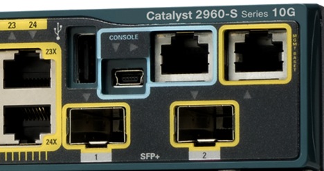
Всегда выделен голубым цветом. С недавних пор стало возможным управление по USB.
А это консольный кабель cisco:

Раньше он поставлялся в каждой коробке, теперь зачастую стоит отдельных денег. В принципе подходит аналогичный кабель от HP.
Проблема в том, что современные ПК зачастую не имеют COM-порта. На выручку приходят частоиспользуемые конвертеры USB-to-COM:


Либо редкоиспользуемые для этих целей конвертеры RS232-Ethernet
После того, как вы воткнули кабель, определили номер COM-порта, для подключения можно использовать Hyperterminal или Putty в Виндоус и Minicom в Линукс.
Управление через консоль доступно сразу, а вот для телнета нужно установить пароль. Как это сделать?
Обратимся к PT.
Начнём с создания маршрутизатора: выбираем его на панели внизу и переносим на рабочее пространство. Даём какое-нибудь название
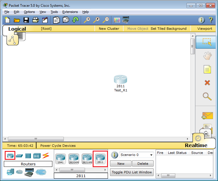
Что бы вы делали, если бы это был самый взаправдашний железный маршрутизатор? Взяли бы консольный кабель и подключились им в него и в компьютер. То же самое сделаем и тут:
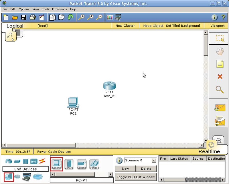
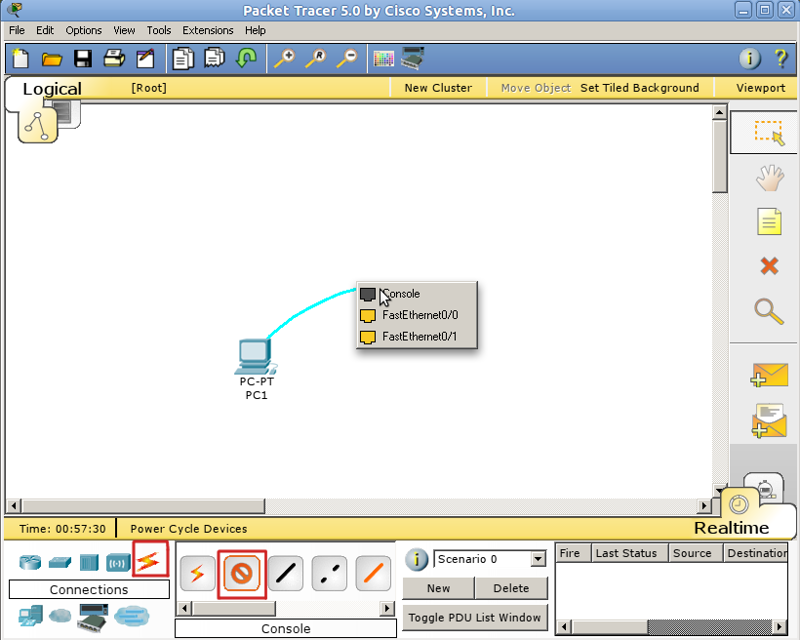
Кликом по компьютеру вызываем окно настройки, в котором нас интересует вкладка Desktop. Далее выбираем Terminal, где нам даётся выбор параметров

Впрочем, все параметры по умолчанию нас устраивают, и менять их особо смысла нет.
Если в энергонезависимой памяти устройства отсутствует конфигурационный файл (startup-config), а так оно и будет при первом включении нового железа, нас встретит Initial Configuration Dialog prompt:

Вкратце, это такой визард, позволяющий шаг за шагом настроить основные параметры устройства (hostname, пароли, интерфейсы). Но это неинтересно, поэтому отвечаем no и видим приглашение
Router>Это стандартное совершенно для любой линейки cisco приглашение, которое характеризует пользовательский режим, в котором можно просматривать некоторую статистику и проводить самые простые операции вроде пинга. Ввод знака вопроса покажет список доступных команд:

Грубо говоря, это режим для сетевого оператора, инженера первой линии техподдержки, чтобы он ничего там не повредил, не напортачил и лишнего не узнал.
Гораздо большие возможности предоставляет режим с говорящим названием привилегированный. Попасть в него можно, введя команду >enable. Теперь приглашение выглядит так:
Router#Здесь список операций гораздо обширнее, например, можно выполнить одну из наиболее часто используемых команд, демонстрирующую текущие настройки устройства ака “конфиг” #show running-config. В привилегированном режиме вы можете просмотреть всю информацию об устройстве.
Прежде, чем приступать к настройке, упомянем несколько полезностей при работе с cisco CLI, которые могут сильно упростить жизнь:
— Все команды в консоли можно сокращать. Главное, чтобы сокращение однозначно указывало на команду. Например, show running-config сокращается до sh run. Почему не до s r? Потому, что s (в пользовательском режиме) может означать как команду show, так и команду ssh, и мы получим сообщение об ошибке % Ambiguous command: «s r» (неоднозначная команда).
— Используйте клавишу Tab и знак вопроса. По нажатию Tab сокращенная команда дописывается до полной, а знак вопроса, следующий за командой, выводит список дальнейших возможностей и небольшую справку по ним (попробуйте сами в PT).
— Используйте горячие клавиши в консоли:
Ctrl+A — Передвинуть курсор на начало строки
Ctrl+E — Передвинуть курсор на конец строки
Курсорные Up, Down — Перемещение по истории команд
Ctrl+W — Стереть предыдущее слово
Ctrl+U — Стереть всю линию
Ctrl+C — Выход из режима конфигурирования
Ctrl+Z — Применить текущую команду и выйти из режима конфигурирования
Ctrl+Shift+6 — Остановка длительных процессов (так называемый escape sequence)
— Используйте фильтрацию вывода команды. Бывает, что команда выводит много информации, в которой нужно долго копаться, чтобы найти определённое слово, например.
Облегчаем работу с помощью фильтрации: после команды ставим |, пишем вид фильтрации и, собственно, искомое слово(или его часть). Виды фильтрации (ака модификаторы вывода):
begin — вывод всех строк, начиная с той, где нашлось слово,
section — вывод секций конфигурационного файла, в которых встречается слово,
include — вывод строк, где встречается слово,
exclude — вывод строк, где НЕ встречается слово.
Но вернемся к режимам. Третий главный режим, наряду с пользовательским и привилегированным: режим глобальной конфигурации. Как понятно из названия, он позволяет нам вносить изменения в настройки устройства. Активируется командой #configure terminal из привилегированного режима и демонстрирует такое приглашение:
Router(config)#В режиме глобальной конфигурации не выполняются довольно нужные порой команды других режимов (тот же show running-config, ping, etc.). Но есть такая полезная штука, как do. Благодаря ей мы можем, не выходя из режима конфигурирования, выполнять эти самые команды, просто добавляя перед ними do. Примерно так:
Router(config)#do show running-configНастройка доступа по Telnet
Из этого-то режима мы и настроим интерфейс для подключения компьютера через telnet:
Команда для перехода в режим конфигурации интерфейса FastEthernet 0/0:
# Router(config)# interface fa0/0По умолчанию все интерфейсы отключены (состояние administratively down). Включаем интерфейс:
Router(config-if)#no shutdownНастроим IP-адрес:
Router(config-if)#ip address 192.168.1.1 255.255.255.0shutdown — означает “выключить интерфейс”. Соответственно, если вы хотите отменить действие команды, то используйте слово no перед ней. Это правило общее для CLI и применимо к большинству команд.
Подключаемся. Для этого надо использовать кроссоверный кабель. (Хотя в реальной жизни это зачастую уже необязательно – все карточки умеют понимать приём/передачу, однако встречаются ещё маршрутизаторы, порты которых не поднимаются при использовании неправильного типа кабеля — так что будьте внимательны)
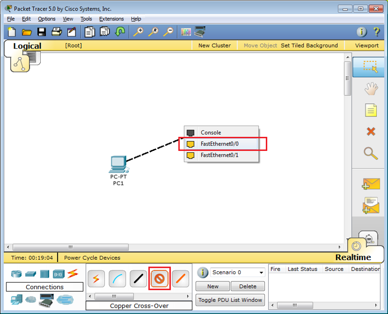
Настраиваем IP-адрес компьютера через Desktop.
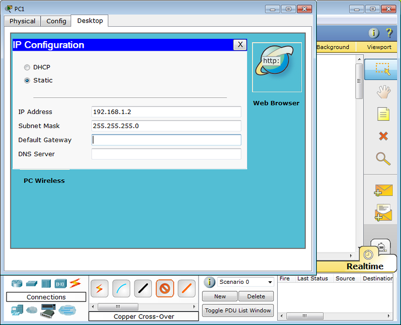
И пробуем подключиться, выбрав Command Prompt в панели Desktop:
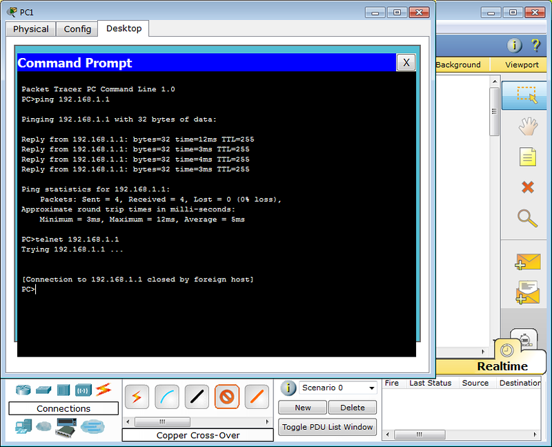
Как и ожидалось, циска не пускает без пароля. В реальной жизни обычно выдаёт фразу “Password required, but none set”
Пароли
Подключение по telnet или ssh называется виртуальным терминалом (vt) и настраивается следующим образом:
Router(config)#line vty 0 4
Router(config-line)#password <i>cisco</i>
Router(config-line)#login
0 4 — это 5 пользовательских виртуальных терминалов=telnet сессий.
Этого уже достаточно, чтобы попасть в пользовательский режим, но недостаточно для привилегированного:

Настроим пароль для enable-режима:
Router(config)#enable secret <i>test</i>
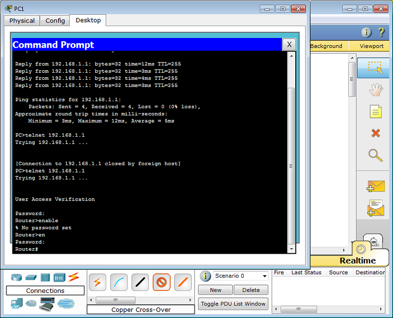
Чем отличается secret от password? Примерно тем же, чем ssh от telnet. При настройке secret пароль хранится в зашифрованном виде в конфигурационном файле, а password – в открытом. Поэтому рекомендуется использование secret.
Если вы всё-таки задаёте пароль командой password, то следует применить так же service password-encryption, тогда ваш пароль в конфигурационном файле будет зашифрован:
line vty 0 4
 password 7 08255F4A0F0A0111
Один мой знакомый рассказал мне историю:
Стоял он как-то курил возле одного из своих узлов, находящемся в жилом доме. С сумкой для инструментов, ноутбук в руках. Вдруг подходит двое алкашей с пакетом и предлагают купить, раскрывая пакет и показывая какой-то свич. Просят 500 рублей. Ну он купил. По меткам и модели свича парень сделал вывод какому провайдеру он принадлежит. Пришёл домой, начал ковырять — телнет закрыт, консоль запаролена. Слил конфиг по snmp. Пароли в открытом виде хранятся, имя с головой выдаёт провайдера. С их админом он знаком лично, позвонил ему вместо “Здрасьти” выдал логин и пароль в трубку. Слышно было, как скрипел мозг первые секунд 20: везде аксес-листы, авторизация, привязка к мак-адресу. Как?! В общем, всё хорошо, что хорошо кончается.
Немного об этом можно почитать здесь. Ну или чуть более по-русски, тут.
Хотим обратить ваше внимание:
сейчас принятно настраивать доступы не через виртуальные терминалы, а командами #username и #aaa new-model. В версии PT 5.3.2 они уже есть и вполне работают.
Для этого нужно выполнить:
Router(config)#aaa new-model
Router(config)#username admin password 1234
Первая команда служит для активации новой модели
ААА (Authentication, Authorization, Accounting). Это нужно для того, чтобы была возможность использовать для аунтетификации на устройстве RADIUS или TACACS сервер. Если отдельно это не настроено, то будет использоваться локальная база пользователей, задаваемая командой username.

Будьте внимательны: приоритет команды aaa new-model выше, чем команд виртуальных терминалов и поэтому даже несмотря на то, что у вас настроен password в режиме line vty, если у вас не будет пользователей в локальной базе, зайти на устройство удалённо уже не получится.

Теперь при подключении маршрутизатор запросит имя пользователя и соответствующий ему пароль.

При более глубокой настройке line vty существует одна опасность.

Есть такой параметр: access-class. Его настройка позволяет ограничить IP-адреса, с которых возможно подключение. И вот однажды я, как умная маша, решил заняться безопасностью в сети и на всём почти оборудование понаставил эти аксес-листы, чтобы комар не пролетел. В один прекрасный момент пришлось выехать в поле и в тот день я проклял свою аккуратность – никуда не мог достучаться – малейшей лазейки не оставил. В общем будьте с этой командой внимательны или оставляйте для себя лазейки.

При работе с access-list'ами и прочими опасными вещами, неправильная настройка которых может лишить вас доступа к устройству, можно использовать замечательную команду reload in min, где min время в минутах. Эта команда перезагрузит устройство по истечении указанного времени, если ее не прервать командой reload cancel. Т.е. схема работы такова: вы удаленно копаете что-то, что может в теории (закон Мерфи не забываем) прервать ваш сеанс связи с устройством. Сохраняем текущий (рабочий) конфиг в startup-config (он используется при загрузке), ставим reload in 15, вводим ключевую команду, относительно которой у нас сомнения ;-), и получаем обрыв связи, худшие опасения оправдались. Ждем 15 минут, устройство перегружается с рабочим конфигом, коннект — вуаля, связь есть. Либо (если связь не прервалась) проверяем, что все работает, и делаем reload cancel.

Если вы хотите ограничить паролем доступ через консольный порт, вам понадобятся команды


Router(config)#line console 0
Router(config-line)#login
Router(config-line)#password <i>cisco</i>
Privilege Level
Ещё один важный момент, которому в статьях уделяют мало внимания: privelege level.
Как понятно из латинского звучания — это уровень прав пользователя. Всего существует 16 уровней: 0-15.
privilege level 0 — это команды disable, enable, exit, help и logout, которые работают во всех режимах
privilege level 1 — Это команды пользовательского режима, то есть как только вы попадаете на циску и увидите приглашение Router> вы имеете уровень 1.
privilege level 15 — Это команды привилегированного режима, вроде, как root в Unix’ах
Пример1
Router(config)#line vty 0 4
Router(config-line)privilege level 15
После входа на маршрутизатор при такой настройке вы сразу увидите Router# со всеми вытекающими правами.
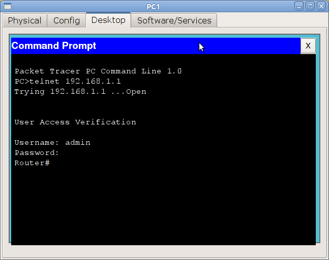
Все уровни со 2 по 14 настраиваются вручную. То есть, например, вы можете дать добро пользователю с privelege level 2 на выполнение команды show running-config
Пример2
Настроить права для конкретного пользователя поможет уже упомянутая прежде команда username
Router(config)#username pooruser privilege 2 secret poorpass
Router(config)#privilege exec level 2 show running-config
Router(config)#enable secret level 2 l2poorpass
В первой строке назначаем уровень прав пользователю, во второй команду, разрешенную для этого уровня, в третьей задаём пароль для входа в привилегированный режим с этим уровнем.
После этого из пользовательского режима вы можете выполнить команду enable 2 и введя пароль l2poorpass попасть в привилегированный режим, в котором будут доступны все команды уровня 1 + команды уровня 2.

Для чего это может быть нужно? В российских реалиях практически ни для чего, потому что обычно на устройство нужно заходить инженерам сразу с полными правами. Ну разве что 15-й уровень ставят, чтобы двойную аутентификацию не проходить. А все другие уровни опять же для того, чтобы персонал младшего состава (техподдержка, например) мог зайти и промониторить какие-то параметры или настроить некритичную функцию.
SSH
Нельзя не упомянуть о том, что telnet — протокол незащищённый и передаёт пароль и данные в открытом виде. С помощью любого анализатора пакетов можно вычислить пароль.
Поэтому крайне рекомендуем использовать ssh — любые устройства cisco с не самой урезанной прошивкой способны выступать ssh-сервером.
Следующий набор команд позволит вам включить ssh и отключить доступ по telnet:
	Router(config)#hostname R0
	Router(config)#ip domain-name cisco-dmn
	Router(config)#crypto key generate rsa
	Router(config)#line vty 0 4
	Router(config-line)#transport input ssh
Имя хоста должно отличаться от Router, обязательно должно быть задано имя домена. Третьей строкой генерируется ключ и далее разрешается только ssh. Длина ключа должна быть более 768 бит, если вы желаете использовать ssh версии 2, а вы желаете этого. Всё.
Ещё одно финальное внимание новичкам: не забывайте о команде write memory — это сохранение текущей конфигурации. Впрочем, достаточно два раза обжечься, забыв сохранить, чтобы навсегда заработать иммунитет к этому — кто кодил по ночам или писал курсовую, тот поймёт.
Используя PT, мы будем настраивать оборудование не через терминал или телнет, а непосредственно через CLI устройства, которое вызывается кликом по иконке роутера — так удобнее:
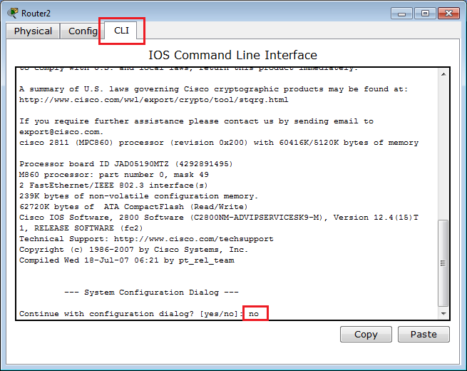
Ну и на сладенькое: сброс пароля
Так, а что же делать, если на стол легла вам бушная циска с неизвестным паролем или вы очень невовремя забыли его? Вообще-то это многократно
описано и легко гуглится, но повторить это необходимо.
Практически на любом сетевом устройстве есть возможность сбросить пароль, имея физический доступ. Если сделать это невозможно или это отдельная платная услуга, то скорее всего в ваших руках находится какая-то русская поделка (не в обиду, конечно, нашим производителям, но дважды я такие строки читал в документации:))
Итак, cisco:
1) Подключаетесь к устройству консольным кабелем,
2) Отправляете его в ребут (хоть по питанию, хоть командой #reload)
3) Когда на экране побежит такая строчка ########…###, означающая загрузку образа (40-60 секунд после включения), необходимо отправить сигнал Break. Как это сделать в разных программах читать тут. Вы попадаете в режим ROMMON.
4) В этом режиме введите команду: confreg 0x2142, она заставит устройство игнорировать startup-config при загрузке.
5) Введите reset для перезагрузки
6) После загрузки running-config будет девственно чистым, а startup-config содержит по-прежнему последнюю сохранённую конфигурацию. Сейчас самое время поменять пароль или слить конфиг.
7) Самое важное: верните обратно регистры:
Router(config)#config-register 0x2102Если вы этого не сделаете, то вся ваша конфигурация будет актуальна до первого ребута) И хорошо, если это устройство стоит рядом, и вы вспомните, что накосячили. Мне не повезло)
В следующей статье мы обратимся к вланам и локальной сети. Обязательно к прочтению:
OSI.
VLAN
Незарегистрированные читатели Хабрахабра могут задать свои вопросы в ЖЖ.
Хочу поблагодарить пользователя thegluck за помощь в написании этой статьи.
Telnet is used as a remote login program.If you want to login to a machine which is far away from you,you must have to use a remote login program and telnet is one of them.Telnet is a remote connection protocol which works on port 23.Here in this article to test remote login through telnet i have used packet tracer software.In this article i have mentioned all the possible way to configure telnet on router or switch.If anyone know some more ways to configure telnet on a router or a switch i will be very happy to know t from our comment section.

Telnet configuration on Router:
here i am going to configure and enable telnet program on router R1 with password enable on it.
R1>enable
R1#config t
Enter configuration commands, one per line. End with CNTL/Z.
R1(config)#enable password ccna123
R1(config)#line vty 0 5
R1(config-line)#login
% Login disabled on line 194, until ‘password’ is set
% Login disabled on line 195, until ‘password’ is set
% Login disabled on line 196, until ‘password’ is set
% Login disabled on line 197, until ‘password’ is set
% Login disabled on line 198, until ‘password’ is set
% Login disabled on line 199, until ‘password’ is set
Note the above ouput:The above lines shows that the connection was refused. This is because, login is disabled on all the six telnet sessions we created until a password is set. To set ‘telnet 123’ as a password, go back to the router and type
R1(config-line)#password telnet 123
R1(config-line)#login
R1(config-line)#
Now if we try to login from our pc remotely using telnet :
PC>telnet 1.0.0.1
Trying 1.0.0.1 …Open
User Access Verification
Password:
Password:
R1>
Now you can see telnet is working properly.
Now see how to configure telnet or enable telnet with no password set.
R1>enable
R1#config t
Enter configuration commands, one per line. End with CNTL/Z.
R1(config)#enable password ccna123
R1(config)#line vty 0 5
R1(config-line)#no login
In above condition when anyone try to login from PC using telnet he/she can easily login to router without any password.Telnet will not ask any password if your router is configured in this way and which may results in a disaster if your router goes in a wrong hand.
So if you don’t want to face such situation you must provide atleast some basic security on your router while configuring telnet.
Now see how to configure telnet with username and password enabled.
Telnet configuration on Router R2 with username and Password.
R2>enable
R2#config t
Enter configuration commands, one per line. End with CNTL/Z.
R2(config)#username satish password shivangi
R2(config)#username tiwary password shivangigarg
R2(config)#username vit password slashroot
R2(config)#line vty 0 5
R2(config-line)#login local
R2(config-line)#exit
R2(config)#enable password shivangi123
Explanation of above command:In above command we have configured and enabled telnet service on router R2 with user and each user have its own password.
Now lets try to connect from PC command promt.
PC>telnet 3.0.0.1
Trying 3.0.0.1 …Open
User Access Verification
Username: satish
Password:
So you can see our telnet is working properly according to our configuration. Now similarly login to router from different PC using different users and then go to router to see the login users or to monitor who is login in your router and from which PC they are login.
R2#show users
Line User Host(s) Idle Location
* 0 con 0 idle 00:00:00
196 vty 0 satish idle 00:02:07 1.0.0.2
197 vty 1 tiwary idle 00:00:49 1.0.0.3
198 vty 2 vit idle 00:00:11 3.0.0.3
Interface User Mode Idle Peer Address
Now learn how to Configure Telnet to login directly to Privilege Mode:
R2#config t
Enter configuration commands, one per line. End with CNTL/Z.
R2(config)#username Admin privilege 15 secret redhat123
R2(config)#
Now to test above telnet configuration go to PC command promt and try to login using telnet.
PC>telnet 3.0.0.1
Trying 3.0.0.1 …Open
User Access Verification
Username: Admin
Password:
R2#
you can clearly see the user Admin directly login to privilege mode.
Now again go to to router to see which users are login to your router and when you will use show users command,you will find admin user name also there.
R2#show users
Line User Host(s) Idle Location
* 0 con 0 idle 00:00:00
196 vty 0 satish idle 00:05:05 1.0.0.2
197 vty 1 tiwary idle 00:03:46 1.0.0.3
198 vty 2 vit idle 00:03:10 3.0.0.3
199 vty 3 Admin idle 00:00:27 3.0.0.5
Interface User Mode Idle Peer Address
Now Learn how to configure telnet to login with an encrypted username and password.
R2#config t
Enter configuration commands, one per line. End with CNTL/Z.
R2(config)#username shivangi secret satish123
To test this configuration see below commands carefully.
PC>telnet 3.0.0.1
Trying 3.0.0.1 …Open
User Access Verification
Username: shivangi
Password:
R2>
R2#show users
Line User Host(s) Idle Location
* 0 con 0 idle 00:00:00
196 vty 0 satish idle 00:09:21 1.0.0.2
197 vty 1 shivangi idle 00:00:22 1.0.0.3
198 vty 2 vit idle 00:07:25 3.0.0.3
199 vty 3 Admin idle 00:04:42 3.0.0.5
Interface User Mode Idle Peer Address
In below command you will have to see whethershivangi user has an encrypted password or not.If not then your configuration is wrong,if yes the you have configured it correctly.
R2#show run
Building configuration…
Current configuration : 904 bytes
!
enable password shivangi123
!
username Admin privilege 15 secret 5 $1$mERr$/.1oOMouj/h0tWhPw9K6J1
username satish password 0 shivangi
username shivangi secret 5 $1$mERr$N5gbd/27lp5mDoGBcEZGc.
username tiwary password 0 shivangigarg
username vit password 0 slashroot
Explanation of above output:Now you can clearly see user shivangi has an encrypted password.
Now you can also encrypt all password provided on router using below command:
This will provide additional security to your router.
R2(config)#service password-encryption
R2(config)#exit
Now lets check the result, and you will find your all password used on this routers are encrypted now.
R2#show run
Building configuration…
Current configuration : 951 bytes
!
service password-encryption
!
hostname R2
!
enable password 7 083244471F180B101B5A5E57
!
username Admin privilege 15 secret 5 $1$mERr$/.1oOMouj/h0tWhPw9K6J1
username satish password 7 083244471F180B101B
username shivangi secret 5 $1$mERr$N5gbd/27lp5mDoGBcEZGc.
username tiwary password 7 083244471F180B101B0C0D162D
username vit password 7 0832404F1A1117181D1F
If you have any other method to configure telnet on cisco router or cisco switches,leave your command through comment section.Keep reading and keep sharing your knowledge.
![]()
Author and Trainer for ccna linux ccna-security ccna-cyber-ops ccnp rhce rhcss rhca devops aws ceh cloud-computing mcse cissp python ruby firewall at ETHICAL HACKING TUITION CENTER JAIPUR(EHTC)
https://linuxtiwary.com and http://youtube.com/slashrootdotin and www.slashroot.in
View all posts by satish tiwary