Время на прочтение
9 мин
Количество просмотров 137K
В прошлой статье мы рассмотрели основные моменты настройки сетевого оборудования HUAWEI и остановились на статической маршрутизации. В сегодняшнем топике речь пойдёт о динамической маршрутизации по протоколу OSPF совместно с маршрутизаторами Cisco. Добро пожаловать под кат.
Теория
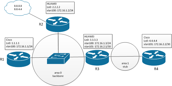
Итак, в нашей супер сети присутствуют 4 маршрутизатора: два HUAWEI и два Cisco. Роутер R2 будет являться ASBR, R3 — ABR.
Напомню, что в OSPF маршрутизаторы делятся на несколько типов:
- Внутренний маршрутизатор (internal router) — маршрутизатор, все интерфейсы которого принадлежат одной зоне. У таких маршрутизаторов только одна база данных состояния каналов.
- Пограничный маршрутизатор (area border router, ABR) — соединяет одну или больше зон с магистральной зоной и выполняет функции шлюза для межзонального трафика. У пограничного маршрутизатора всегда хотя бы один интерфейс принадлежит магистральной зоне. Для каждой присоединенной зоны маршрутизатор поддерживает отдельную базу данных состояния каналов.
- Магистральный маршрутизатор (backbone router) — маршрутизатор, у которого всегда хотя бы один интерфейс принадлежит магистральной зоне. Определение похоже на пограничный маршрутизатор, однако магистральный маршрутизатор не всегда является пограничным. Внутренний маршрутизатор интерфейсы которого принадлежат нулевой зоне, также является магистральным.
- Пограничный маршрутизатор автономной системы (AS boundary router, ASBR) — обменивается информацией с маршрутизаторами, принадлежащими другим автономным системам или не-OSPF маршрутизаторами. Пограничный маршрутизатор автономной системы может находиться в любом месте автономной системы и быть внутренним, пограничным или магистральным маршрутизатором.[1]
Area 0 — магистральная (backbone) зона, area 1 — тупиковая зона (stub).
- Магистральная (транзитная) зона (backbone (transit) area) — зона используемая для подключения других зон.
- Тупиковая зона (stub area) — зона, не принимающая информацию о маршрутах, являющихся внешними для данной автономной системы.
- Полностью тупиковая зона (totally stub area) — зона, не принимающая информацию о внешних маршрутах и маршрутах из других автономных систем.
Итак, приступим к настройке.
Первоначальная настройка:
Для начала нам необходимо создать vlan интерфейс, назначить ему соответствующий ip адрес и разрешить прохождение трафика через физический интерфейс, таким образом добиться ip коннективити между девайсами.
После этого включим процесс OSPF на маршрутизаторах:
Cisco:
R1(config)#router ospf 1
R1(config-router)#network 172.16.1.0 0.0.0.255 area 0
R1(config-router)#network 1.1.1.1 0.0.0.0 area 0
R1(config-router)#router
R1(config-router)#router-id 1.1.1.1
HUAWEI:
[R2]ospf 1 router-id 2.2.2.2
[R2-ospf-1]area 0
[R2-ospf-1-area-0.0.0.0]network 172.16.1.0 0.0.0.255
[R2-ospf-1-area-0.0.0.0]network 2.2.2.2 0.0.0.0
[R2-ospf-1-area-0.0.0.0]
Естественно, при настройке необходимо изменить значения router-id и анонсируемые сети для разных зон. Таким образом, первоначальная конфигурация OSPF будет выглядеть так:
R1 [Cisco]:
router ospf 1
 router-id 1.1.1.1
 log-adjacency-changes
 redistribute static
 network 1.1.1.1 0.0.0.0 area 0
 network 172.16.1.0 0.0.0.255 area 0
!
R2 [HUAWEI]:
ospf 1 router-id 2.2.2.2
 area 0.0.0.0
  network 172.16.1.0 0.0.0.255
  network 2.2.2.2 0.0.0.0
#
R3 [HUAWEI]:
ospf 1 router-id 3.3.3.3
 area 0.0.0.0
  network 3.3.3.0 0.0.0.3
  network 172.16.1.0 0.0.0.255
 area 0.0.0.1
  network 172.16.2.0 0.0.0.3
#
R4: [Cisco]
router ospf 1
 log-adjacency-changes
 area 1 stub
 network 4.4.4.4 0.0.0.0 area 1
 network 172.16.2.0 0.0.0.3 area 1
!
Маршрутизатор R4 является ABR, поэтому в нём описываются несколько зон. Пока мы не будем переводить зону 1 в состояние stub. Посмотрим, что у нас получилось:
Switch#show ip ospf neighbor

Neighbor ID     Pri   State           Dead Time   Address         Interface
2.2.2.2           1   FULL/BDR        00:00:39    172.16.1.2      Vlan100
3.3.3.3           1   FULL/DR         00:00:31    172.16.1.3      Vlan100
Switch#
DR, BDR, DROTHER
Мы видим, что маршрутизаторы R2 и R3 выбрались BDR и DR, соответственно. Напомню что это означает. Так как познать всю теорию OSPF не является целью нашего повествования, опишем эти понятия вкратце.
- DR, designated router (выделенный маршрутизатор) — маршрутизатор который управляет процессом обмена сообщениями в сети OSPF.
- BDR, backup designated router (резервный выделенный маршрутизатор) — маршрутизатор, который заменяет DR в случае выбывания последнего.
Выбор BDR и DR осуществляется на основе приоритета маршрутизатора, но по умолчанию приоритеты всех устройств равны 1. В этом случае процесс выбора проходит по идентификатору маршрутизатора, что мы и наблюдаем. Но есть одно НО. Если DR и BDR уже выбраны, перевыборы не происходят. Действует принцип: кто первый встал того и тапки. Проверим. Для этого исключим из процесса маршрутизатор R2.
[R2]ospf 1
[R2-ospf-1]area 0
[R2-ospf-1-area-0.0.0.0]undo network 172.16.1.0 0.0.0.255
[R2-ospf-1-area-0.0.0.0]
Теперь R1 стал BDR, R3 же остался DR:
R1#show ip ospf neighbor

Neighbor ID     Pri   State           Dead Time   Address         Interface
3.3.3.3           1   FULL/DR         00:00:33    172.16.1.3      Vlan100
R1#
[R3]display ospf peer

         OSPF Process 1 with Router ID 3.3.3.3
                 Neighbors

 Area 0.0.0.0 interface 172.16.1.3(Vlanif100)'s neighbors
 Router ID: 1.1.1.1          Address: 172.16.1.1
   State: Full  Mode:Nbr is  Slave  Priority: 1
   !!!!!DR: 172.16.1.3  BDR: 172.16.1.1!!!!!  MTU: 1500
   Dead timer due in 35  sec
   Retrans timer interval: 4
   Neighbor is up for 00:35:59
   Authentication Sequence: [ 0 ]

                 Neighbors

 Area 0.0.0.1 interface 172.16.2.1(Vlanif101)'s neighbors
 Router ID: 4.4.4.4          Address: 172.16.2.2
   State: Full  Mode:Nbr is  Master  Priority: 1
   DR: 172.16.2.2  BDR: 172.16.2.1  MTU: 1500
   Dead timer due in 33  sec
   Retrans timer interval: 5
   Neighbor is up for 00:56:48
   Authentication Sequence: [ 0 ]

[R3]
Сейчас мы снова включим в процесс OSPF на роутере R2 сеть 172.16.1.0/24.
[R2]ospf 1
[R2-ospf-1]area 0
[R2-ospf-1-area-0.0.0.0]network 172.16.1.0 0.0.0.255
[R2-ospf-1-area-0.0.0.0]
Теперь посмотрим состояние маршрутизаторов:
R1#show ip ospf neighbor

Neighbor ID     Pri   State           Dead Time   Address         Interface
2.2.2.2           1   FULL/DROTHER    00:00:36    172.16.1.2      Vlan100
3.3.3.3           1   FULL/DR         00:00:39    172.16.1.3      Vlan100
R1#
Второй маршрутизатор перешёл в состояние DROTHER, т. е. он не является ни DR, ни BDR. Да будет так.
Межзональный обмен маршрутами
Теперь посмотрим, что мы имеем в таблицах маршрутизации.
R1#show ip route
Codes: C - connected, S - static, R - RIP, M - mobile, B - BGP
       D - EIGRP, EX - EIGRP external, O - OSPF, IA - OSPF inter area
       N1 - OSPF NSSA external type 1, N2 - OSPF NSSA external type 2
       E1 - OSPF external type 1, E2 - OSPF external type 2, E - EGP
       i - IS-IS, su - IS-IS summary, L1 - IS-IS level-1, L2 - IS-IS level-2
       ia - IS-IS inter area, * - candidate default, U - per-user static route
       o - ODR, P - periodic downloaded static route

Gateway of last resort is not set

     1.0.0.0/32 is subnetted, 1 subnets
C       1.1.1.1 is directly connected, Loopback0
     2.0.0.0/32 is subnetted, 1 subnets
O       2.2.2.2 [110/1] via 172.16.1.2, 00:05:59, Vlan100
     3.0.0.0/32 is subnetted, 1 subnets
O       3.3.3.3 [110/1] via 172.16.1.3, 00:05:59, Vlan100
     4.0.0.0/32 is subnetted, 1 subnets
O IA    4.4.4.4 [110/3] via 172.16.1.3, 00:05:59, Vlan100
     172.16.0.0/16 is variably subnetted, 2 subnets, 2 masks
C       172.16.1.0/24 is directly connected, Vlan100
O IA    172.16.2.0/30 [110/2] via 172.16.1.3, 00:05:59, Vlan100
R1#
Флаги IA означают, что маршрут пришёл из другой зоны OSPF.
То же самое на HUAWEI.
[R2]disp ip routing-table
Route Flags: R - relay, D - download to fib
------------------------------------------------------------------------------
Routing Tables: Public
         Destinations : 10       Routes : 10

Destination/Mask    Proto   Pre  Cost      Flags NextHop         Interface

        1.1.1.1/32  OSPF    10   2           D   172.16.1.1      Vlanif100
        2.2.2.2/32  Direct  0    0           D   127.0.0.1       LoopBack0
        3.3.3.3/32  OSPF    10   1           D   172.16.1.3      Vlanif100
        4.4.4.4/32  OSPF    10   3           D   172.16.1.3      Vlanif100
      127.0.0.0/8   Direct  0    0           D   127.0.0.1       InLoopBack0
      127.0.0.1/32  Direct  0    0           D   127.0.0.1       InLoopBack0
     172.16.1.0/24  Direct  0    0           D   172.16.1.2      Vlanif100
     172.16.1.2/32  Direct  0    0           D   127.0.0.1       Vlanif100
     172.16.2.0/30  OSPF    10   2           D   172.16.1.3      Vlanif100

[R2]
В глобальной таблице маршрутизации явно не видно, что маршрут 4.4.4.4/32 пришёл из другой зоны. Посмотрим более детально маршруты по протоколу OSPF.
[R2]dis ospf routing

         OSPF Process 1 with Router ID 2.2.2.2
                  Routing Tables

 Routing for Network
 Destination        Cost  Type       NextHop         AdvRouter       Area
 2.2.2.2/32         0     Stub       2.2.2.2         2.2.2.2         0.0.0.0
 172.16.1.0/24      1     Transit    172.16.1.2      2.2.2.2         0.0.0.0
 1.1.1.1/32         2     Stub       172.16.1.1      1.1.1.1         0.0.0.0
 3.3.3.3/32         1     Stub       172.16.1.3      3.3.3.3         0.0.0.0
 4.4.4.4/32         3     Inter-area 172.16.1.3      3.3.3.3         0.0.0.0
 172.16.2.0/30      2     Inter-area 172.16.1.3      3.3.3.3         0.0.0.0

 Total Nets: 6
 Intra Area: 4  Inter Area: 2  ASE: 0  NSSA: 0

[R2]
Здесь мы видим, что маршруты 4.4.4.4/32 и 172.16.2.0/30 пришли из другой зоны (Inter-area).
Редистрибьюция маршрутов
Усложним ситуацию. Вспомним, что маршрутизатор R2 по совместительству является пограничным маршрутизатором автономной системы, т. е. за ним потенциально могут быть другие маршрутизаторы. Добавим парочку статических маршрутов в рай, т. е. туда, откуда не возвращаются, да простят меня DNS’ы гугла.
[R2]ip route-static 8.8.8.8 32 NULL0
[R2]ip route-static 8.8.4.4 32 NULL0
И добавим редистрибьюцию статических маршрутов:
[R2]ospf 1
[R2-ospf-1]import-route static
Т. о. образом конфиг секции OSPF на маршрутизаторе R2:
[R2-ospf-1]di th
#
ospf 1 router-id 2.2.2.2
 import-route static
 area 0.0.0.0
  network 2.2.2.2 0.0.0.0
  network 172.16.1.0 0.0.0.255
#
return
[R2-ospf-1]
Посмотрим таблицы маршрутизации.
R1#show ip route
Codes: C - connected, S - static, R - RIP, M - mobile, B - BGP
       D - EIGRP, EX - EIGRP external, O - OSPF, IA - OSPF inter area
       N1 - OSPF NSSA external type 1, N2 - OSPF NSSA external type 2
       E1 - OSPF external type 1, E2 - OSPF external type 2, E - EGP
       i - IS-IS, su - IS-IS summary, L1 - IS-IS level-1, L2 - IS-IS level-2
       ia - IS-IS inter area, * - candidate default, U - per-user static route
       o - ODR, P - periodic downloaded static route

Gateway of last resort is not set

     1.0.0.0/32 is subnetted, 1 subnets
C       1.1.1.1 is directly connected, Loopback0
     2.0.0.0/32 is subnetted, 1 subnets
O       2.2.2.2 [110/1] via 172.16.1.2, 00:01:49, Vlan100
     3.0.0.0/32 is subnetted, 1 subnets
O       3.3.3.3 [110/1] via 172.16.1.3, 00:01:49, Vlan100
     4.0.0.0/32 is subnetted, 1 subnets
O IA    4.4.4.4 [110/3] via 172.16.1.3, 00:01:49, Vlan100
     172.16.0.0/16 is variably subnetted, 2 subnets, 2 masks
C       172.16.1.0/24 is directly connected, Vlan100
O IA    172.16.2.0/30 [110/2] via 172.16.1.3, 00:01:50, Vlan100
     8.0.0.0/32 is subnetted, 2 subnets
O E2    8.8.8.8 [110/1] via 172.16.1.2, 00:01:50, Vlan100
O E2    8.8.4.4 [110/1] via 172.16.1.2, 00:01:52, Vlan100
     9.0.0.0/32 is subnetted, 1 subnets
O E2    9.9.9.9 [110/1] via 172.16.1.2, 00:01:52, Vlan100
R1#
Флаг E означает, что маршруты импортировались из другого протокола маршрутизации.
То же самое на HUAWEI:
[R3]disp ospf routing

         OSPF Process 1 with Router ID 3.3.3.3
                  Routing Tables

 Routing for Network
 Destination        Cost  Type       NextHop         AdvRouter       Area
 3.3.3.3/32         0     Stub       3.3.3.3         3.3.3.3         0.0.0.0
 172.16.1.0/24      1     Transit    172.16.1.3      3.3.3.3         0.0.0.0
 172.16.2.0/30      1     Transit    172.16.2.1      3.3.3.3         0.0.0.1
 1.1.1.1/32         2     Stub       172.16.1.1      1.1.1.1         0.0.0.0
 2.2.2.2/32         1     Stub       172.16.1.2      2.2.2.2         0.0.0.0
 4.4.4.4/32         2     Stub       172.16.2.2      4.4.4.4         0.0.0.1

 Routing for ASEs
 Destination        Cost      Type       Tag         NextHop         AdvRouter
 8.8.4.4/32         1         Type2      1           172.16.1.2      2.2.2.2
 8.8.8.8/32         1         Type2      1           172.16.1.2      2.2.2.2

 Total Nets: 8
 Intra Area: 6  Inter Area: 0  ASE: 2  NSSA: 0

[R3]
Настройка тупиковых зон
Переходим к заключительному этапу — настройке тупиковой зоны area 1. Предварительно посмотрим какие маршруты пришли на несправедливо забытый маршрутизатор R4.
R4#show ip route
Codes: C - connected, S - static, R - RIP, M - mobile, B - BGP
       D - EIGRP, EX - EIGRP external, O - OSPF, IA - OSPF inter area
       N1 - OSPF NSSA external type 1, N2 - OSPF NSSA external type 2
       E1 - OSPF external type 1, E2 - OSPF external type 2, E - EGP
       i - IS-IS, su - IS-IS summary, L1 - IS-IS level-1, L2 - IS-IS level-2
       ia - IS-IS inter area, * - candidate default, U - per-user static route
       o - ODR, P - periodic downloaded static route

Gateway of last resort is not set

     1.0.0.0/32 is subnetted, 1 subnets
O IA    1.1.1.1 [110/3] via 172.16.2.1, 00:02:18, Vlan101
     2.0.0.0/32 is subnetted, 1 subnets
S       2.2.2.2 [1/0] via 172.16.2.1
     3.0.0.0/32 is subnetted, 1 subnets
O IA    3.3.3.3 [110/1] via 172.16.2.1, 00:02:18, Vlan101
     4.0.0.0/32 is subnetted, 1 subnets
C       4.4.4.4 is directly connected, Loopback0
     172.16.0.0/16 is variably subnetted, 2 subnets, 2 masks
O IA    172.16.1.0/24 [110/2] via 172.16.2.1, 00:02:18, Vlan101
C       172.16.2.0/30 is directly connected, Vlan101
     8.0.0.0/32 is subnetted, 2 subnets
O E2    8.8.8.8 [110/1] via 172.16.2.1, 00:02:19, Vlan101
O E2    8.8.4.4 [110/1] via 172.16.2.1, 00:02:21, Vlan101
C    192.168.254.0/24 is directly connected, Vlan96
R4#
Видим, что пришли абсолютно все маршруты. Переведём зону 1 в тупиковую.
[R3]ospf 1
[R3-ospf-1]area 1
[R3-ospf-1-area-0.0.0.1]stub
[R3-ospf-1-area-0.0.0.1]
R4(config)#router ospf 1
R4(config-router)#area 1 stub
R4(config-router)#
Смотрим таблицу маршрутизации:
R4#show ip route
Codes: C - connected, S - static, R - RIP, M - mobile, B - BGP
       D - EIGRP, EX - EIGRP external, O - OSPF, IA - OSPF inter area
       N1 - OSPF NSSA external type 1, N2 - OSPF NSSA external type 2
       E1 - OSPF external type 1, E2 - OSPF external type 2, E - EGP
       i - IS-IS, su - IS-IS summary, L1 - IS-IS level-1, L2 - IS-IS level-2
       ia - IS-IS inter area, * - candidate default, U - per-user static route
       o - ODR, P - periodic downloaded static route

Gateway of last resort is 172.16.2.1 to network 0.0.0.0

     1.0.0.0/32 is subnetted, 1 subnets
O IA    1.1.1.1 [110/3] via 172.16.2.1, 00:01:54, Vlan101
     2.0.0.0/32 is subnetted, 1 subnets
O IA    2.2.2.2 [110/2] via 172.16.2.1, 00:00:04, Vlan101
     3.0.0.0/32 is subnetted, 1 subnets
O IA    3.3.3.3 [110/1] via 172.16.2.1, 00:01:54, Vlan101
     4.0.0.0/32 is subnetted, 1 subnets
C       4.4.4.4 is directly connected, Loopback0
     172.16.0.0/16 is variably subnetted, 2 subnets, 2 masks
O IA    172.16.1.0/24 [110/2] via 172.16.2.1, 00:01:54, Vlan101
C       172.16.2.0/30 is directly connected, Vlan101
C    192.168.254.0/24 is directly connected, Vlan96
O*IA 0.0.0.0/0 [110/2] via 172.16.2.1, 00:01:54, Vlan101
R4#
Видим, что пришли все маршруты, кроме маршрутов из других автономных систем. На все остальные адреса пакеты будут маршрутизироваться по вновь пришедшему дефолтному маршруту.
Переведём зону 1 в абсолютно тупиковую. Это можно сделать только на ABR маршрутизаторе.
[R3]ospf 1
[R3-ospf-1]area 1
[R3-ospf-1-area-0.0.0.1]stub no-summary
[R3-ospf-1-area-0.0.0.1]
Посмотрим таблицу маршрутизации:
R4#show ip route
Codes: C - connected, S - static, R - RIP, M - mobile, B - BGP
       D - EIGRP, EX - EIGRP external, O - OSPF, IA - OSPF inter area
       N1 - OSPF NSSA external type 1, N2 - OSPF NSSA external type 2
       E1 - OSPF external type 1, E2 - OSPF external type 2, E - EGP
       i - IS-IS, su - IS-IS summary, L1 - IS-IS level-1, L2 - IS-IS level-2
       ia - IS-IS inter area, * - candidate default, U - per-user static route
       o - ODR, P - periodic downloaded static route

Gateway of last resort is 172.16.2.1 to network 0.0.0.0

     4.0.0.0/32 is subnetted, 1 subnets
C       4.4.4.4 is directly connected, Loopback0
     172.16.0.0/30 is subnetted, 1 subnets
C       172.16.2.0 is directly connected, Vlan101
C    192.168.254.0/24 is directly connected, Vlan96
O*IA 0.0.0.0/0 [110/2] via 172.16.2.1, 00:00:03, Vlan101
R4#
Видим, что теперь все пакеты, кроме подключенных напрямую сетей будут маршрутизироваться по дефолтному маршруту.
На этом всё. Спасибо за внимание.
Список использованных источников
1. OSPF xgu.ru — xgu.ru/wiki/OSPF
2. К. Пакет, Д. Тир: Создание масштабируемых сетей Cisco
3. HedEx Lite — документация по оборудованию HUAWEI.
Материал из Xgu.ru
Перейти к: навигация, поиск
| Данная страница находится в разработке. Эта страница ещё не закончена. Информация, представленная здесь, может оказаться неполной или неверной. Если вы считаете, что её стоило бы доработать как можно быстрее, пожалуйста, скажите об этом. |
- Автор: Наташа Самойленко
На этой странице описывается настройка OSPF на маршрутизаторах Cisco.
Тут описываются не только те настройки, которые наиболее часто встречаются в реальной жизни, то и более редкие.
Кратко основные принципы работы OSPF и основные настройки можно просмотреть в презентации Настройка OSPF на маршрутизаторах Cisco
Содержание
- 1 Описание работы протокола
- 2 Базовые настройки
- 2.1 Выбор идентификатора маршрутизатора (Router ID)
- 2.2 Включение OSPF
- 3 Настройка OSPF для сетей различных типов
- 3.1 OSPF в сетях точка-точка (point-to-point)
- 3.2 OSPF в широковещательных сетях со множественным доступом
- 3.2.1 Выбор DR и BDR
- 3.3 OSPF в NBMA сетях
- 3.3.1 Broadcast mode (Cisco extension)
- 3.3.2 Nonbroadcast mode (RFC 2328 compliant)
- 3.3.2.1 Статическое задание соседей (команда neighbor)
- 3.3.3 Point-to-multipoint mode (RFC 2328 compliant)
- 3.3.4 Point-to-multipoint Nonbroadcast mode (Cisco extension)
- 3.3.5 Point-to-point mode (Cisco extension)
- 4 Изменения параметров протокола
- 4.1 Изменение cost и reference bandwidth
- 4.2 Изменение hello и dead-интервалов
- 4.2.1 Fast Hello
- 4.3 Отключение проверки значения MTU
- 4.4 Изменение administrative distance
- 4.5 Изменение таймеров
- 4.5.1 Вычисления SPF
- 5 Управление информацией о маршрутах
- 5.1 Фильтрация маршрутов
- 5.1.1 ABR type 3 LSA filtering
- 5.2 Суммирование маршрутов
- 5.2.1 Пример настройки
- 5.3 Маршрут по умолчанию
- 5.4 Настройка разных тупиковых зон
- 5.5 Stub router
- 5.1 Фильтрация маршрутов
- 6 Перераспределение маршрутов
- 6.1 Перераспределение статических маршрутов
- 7 База данных состояния каналов (LSDB)
- 8 Просмотр информации OSPF
- 8.1 Таймеры, статистика, общая информация
- 8.2 Дополнительная информация о маршрутах OSPF
- 8.3 Таблица маршрутизации
- 8.4 Информация об интерфейсах
- 8.5 База данных состояния каналов
- 8.5.1 Пример
- 8.6 Информация о ABR
- 8.7 Соседи, установленные отношения соседства
- 8.8 SPF
- 8.9 Virtual link
- 9 Дополнительные возможности
- 9.1 Virtual link
- 9.2 Аутентификация
- 9.2.1 Настройка типа аутентификации для зоны
- 9.2.2 Настройка типа аутентификации и пароля на интерфейсах
- 9.2.3 Аутентификация для virtual link
- 9.3 Защита LSDB от перегрузки
- 9.4 Graceful restart (nonstop forwarding)
- 9.5 OSPF LSA Group Pacing
- 9.6 LSA flooding
- 9.6.1 Блокирование LSA flooding
- 9.6.2 Уменьшение LSA flooding
- 10 Разное
- 10.1 Indication LSA
- 11 Дополнительная информация
[править] Описание работы протокола
Тут описаны кратко основные этапы настройки/работы протокола, а также команды настройки и просмотра, которые используются для каждого этапа (подробнее этапы работы на странице OSPF).
| № | Описание этапа | Команды настройки | Команды просмотра |
|---|---|---|---|
| 1 | Включить OSPF на маршрутизаторе | router ospf 1 | sh ip protocol |
| 2 | Маршрутизатор выбирает Router ID | router-id 1.1.1.1 | sh ip protocol |
| 3 | Включить OSPF на интерфейсах | network 10.0.1.0 0.0.0.0 area 0
(-if)# ip ospf 1 area 0 |
sh ip protocol
sh ip ospf int br |
| 4 | Обнаружение соседей с помощью Hello-пакетов | — | sh ip ospf interface |
| 5 | Установка отношений соседства | — | sh ip ospf neighbor |
| 6 | Синхронизация LSDB | — | sh ip ospf database |
| 7 | Вычисление SPF | — | sh ip ospf |
| 8 | Помещение лучших маршрутов в таблицу маршрутизации | — | sh ip ospf rib
sh ip route |
[править] Базовые настройки

![]()
Пример топологии
[править] Выбор идентификатора маршрутизатора (Router ID)
Router ID можно назначить административно выполнив команду:
dyn3(config-router)#router-id <ip-address>
Если RID не был назначен административно, то он выбирается автоматически, в зависимости от настроек маршрутизатора, по таким правилам:
- Настроен один loopback-интерфейс и несколько интерфейсов с различными адресами:
- Адрес присвоенный loopback-интерфейсу будет Router ID.
- Настроены несколько loopback-интерфейсов с несколькими IP-адресами в каждом:
- Наибольший IP-адрес присвоенный любому из loopback-интерфейсов будет Router ID.
- Настроены несколько интерфейсов с IP-адресом на каждом:
- Наибольший IP-адрес из всех активных интерфейсов будет Router ID.
Перезапустить процесс OSPF можно командой:
dyn3# clear ip ospf process
[править] Включение OSPF
Включить OSPF на интерфейсах в соответствующих сетях:
dyn3(config)# router ospf <process-id>
dyn3(config-router)# network <network> <wildcard mask> area <area-id>
Параметры команды network:
- <network> — непосредственно присоединенная сеть к маршрутизатору.
- <wildcard mask> — маска, которая указывает с помощью 0 какая часть из указанной сети должна совпадать, а с помощью 1 какая часть сети может быть произвольной.
- <area-id> — идентификатор зоны, в которой будет работать интерфейс маршрутизатора. Интерфейс попадет в эту зону при условии, что его IP-адрес совпадает с сетью указанной с помощью network и wildcard mask. Для небольших сетей этот параметр можно указывать равным 0, но для больших сетей необходимо соблюдать иерархический дизайн зон в OSPF. Все обновления OSPF, которые передаются между различными зонами, должны проходить через зону 0.
Команда network делает следующее:
- включает OSPF на интерфейсе, IP-адрес которого совпадает с указанной сетью и маской,
- анонсирует сеть этого интерфейса через другие интерфейсы, на которых включен OSPF.
|
|
В процессе OSPF могут быть настроены команды network с перекрывающимися сетями. Интерфейс будет назначен в зону команды network, которая соответствует максимально IP-адресу этого интерфейса.
То интерфейс с адресом 192.168.1.1 будет в зоне 1, интерфейс с адресом 192.168.1.3 — в зоне 2, а интерфейс с адресом 192.168.2.5 — в зоне 3. |
На маршрутизаторах можно использовать другой вариант включения OSPF, непосредственно на интерфейсе.
Включение OSPF на интерфейсах:
dyn3(config-if)# ip ospf <process-id> area <area-id>
Отличия включения OSPF с помощью команд network и ip ospf area проявляется при использовании secondary адресов:
- При использовании команды network, анонсируются сети любых secondary адресов, которые попадают в сеть;
- Команда ip ospf area по умолчанию анонсирует сети secondary адресов, но эта возможность может быть отключена.
Не анонсировать сети secondary адресов:
dyn3(config-if)# ip ospf <process-id> area <area-id> secondaries none
|
|
При использовании unnumbered интерфейсов, отличается влияние команд ip ospf area и network. Если настроить команду network 192.168.1.1 0.0.0.0 area 1, то и на lo0 и s0/0 будет включен OSPF и они будут в зоне 1. Для того чтобы включить OSPF командой ip ospf area на обоих интерфейсах, необходимо дать команду и на lo0 и на s0/0. |
[править] Настройка OSPF для сетей различных типов
[править] OSPF в сетях точка-точка (point-to-point)
Примеры сетей point-to-point:
- serial-интерфейс, использующий на канальном уровне протоколы PPP или HDLC
- point-to-point подынтерфейс, использующий на канальном уровне протокол Frame Relay
- Туннельный интерфейс
- Тип point-to-point может быть задан и для Ethernet, как правило, если это транзитный линк, который соединяет два устройства
Характеристики работы OSPF в сетях point-to-point:
- По умолчанию Hello Interval равен 10 секундам, Router Dead Interval — 40 секундам
- OSPF автоматически определяет этот тип интерфейса
- Так как на интерфейсах point-to-point есть только два соседа, то нет необходимости выбирать DR и BDR
- Пакеты OSPF отправляются на адрес 224.0.0.5
Обычно в качестве IP-адреса отправителя в пакетах OSPF указывается адрес исходящего интерфейса маршрутизатора.
Однако возможно использование IP unnumbered интерфейсов с OSPF.
Если интерфейс unnumbered и OSPF на primary интерфейсе включается командой network, тогда процесс запускается на обоих интерфейсах. Если OSPF на primary интерфейсе включается через ip ospf [id] area [area], тогда процесс запускается только на нем.
|
|
OSPF не проверяет сеть и маску сети при установке отношений соседства в point-to-point сетях. |
[править] OSPF в широковещательных сетях со множественным доступом
Характеристики работы OSPF в широковещательных сетях:
- Необходимо выбирать DR и BDR.
- Все пакеты предназначенные DR и BDR отправляются на адрес 224.0.0.6.
- Пакеты предназначенные другим маршрутизаторам отправляются на адрес 224.0.0.5.
- Все соседние маршрутизаторы устанавливают полные отношения соседства (full adjacencies) только с DR и BDR.
[править] Выбор DR и BDR
Для того чтобы выбрать для сети DR и BDR, маршрутизаторы просматривают значение приоритета в hello-сообщениях и следуют таким условиям для того чтобы определить какой маршрутизатор выбрать:
- Маршрутизатор с наивысшим значением приоритета становится DR.
- Маршрутизатор со вторым наивысшим значением приоритета становится BDR.
- По умолчанию приоритет интерфейса равен 1. Если у маршрутизаторов одинаковые приоритеты, то DR и BDR выбираются по значению Router ID. Маршрутизатор с наивысшим Router ID становится DR, а маршрутизатор со вторым наивысшим Router ID — BDR.
- Маршрутизатор с приоритетом равным 0 не может стать DR или BDR. Маршрутизатор не ставший DR или BDR называется DROTHER.
- Если в сети появляется новый маршрутизатор с более высоким приоритетом чем у текущего DR, то это не влияет на выбранных DR и BDR, переизбрание их не происходит. DR и BDR меняются только тогда, когда один из них вышел из строя. Если из строя вышел DR, то его заменяет BDR и происходят выборы нового BDR. Если из строя выходит BDR, то выбирается новый BDR.
Для того чтобы определить, что DR вышел из строя BDR использует Wait Timer.
Если в течение этого таймера BDR не получает подтверждения того, что DR отправляет LSA, то он считает, что DR вышел из строя.
Присвоить интерфейсу приоритет:
dyn3(config-if)#ip ospf priority <1-255>
[править] OSPF в NBMA сетях
Общая таблица сравнения различных режимов работы OSPF:
| Режим работы OSPF | Отношения соседства | Выбор DR/BDR | Соответствие RFC | HelloInterval | Адреса подсетей |
|---|---|---|---|---|---|
| Broadcast | Автоматически | Выбирается | Cisco | 10 секунд | Одна подсеть |
| Nonbroadcast | Настраиваются | Выбирается | RFC 2328 | 30 секунд | Одна подсеть |
| Point-to-multipoint | Автоматически | Не выбирается | RFC 2328 | 30 секунд | Одна подсеть |
| Point-to-multipoint nonbroadcast | Настраиваются | Не выбирается | Cisco | 30 секунд | Одна подсеть |
| Point-to-point | Автоматически | Не выбирается | Cisco | 10 секунд | Разные для каждого подынтерфейса |
В сетях NBMA по умолчанию HelloInterval равен 30 секундам, RouterDeadInterval — 120 секундам.
Существует несколько режимов работы OSPF в NBMA сетях.
Выбор режима работы влияет на то, как будет работать hello-протокол:
- каким образом будут передаваться пакеты протокола по нешироковещательной сети,
- будут ли выбираться DR и BDR,
- как будут устанавливаться отношения соседства.
Настройка режима работы OSPF:
dyn3(config-if)#ip ospf network <broadcast | non-broadcast | point-to-multipoint [non-broadcast] | point-to-point >
По умолчанию на интерфейсах настроены такие режимы:
- на подынтерфейсе point-to-point Frame Relay — режим point-to-point;
- на подынтерфейсе point-to-multipoint Frame Relay — режим nonbroadcast;
- на основном (физическом) интерфейсе Frame Relay — режим broadcast.
[править] Broadcast mode (Cisco extension)
Пример настройки интерфейса для работы в broadcast режиме:
dyn3(config)# interface serial 0/0
dyn3(config-if)#encapsulation frame-relay
dyn3(config-if)#ip ospf network broadcast
[править] Nonbroadcast mode (RFC 2328 compliant)
В Nonbroadcast режиме работы:
- эмулируется работа OSPF в широковещательных сетях,
- соседи должны быть настроены вручную,
- hello отправляются unicast,
- требуется выбор DR и BDR,
- как правило, используется в сетях с топологией full mesh.
[править] Статическое задание соседей (команда neighbor)
Статическое задание соседа для установления отношения соседства:
dyn3(config-router)# neighbor <ip-address> [priority <number>] [poll-interval <number>] [cost <number>] [database-filter all]
Опции команды neighbor:
- <ip-address> — IP-адрес соседнего маршрутизатора
- priority <number> — приоритет соседа. По умолчанию 0. Диапазон значений от 0 до 255.
- poll-interval <number> — интервал времени в течение которого NBMA-интерфейс ждет, прежде чем отправить hello-пакет соседу, даже в том случае, если сосед неактивен. Диапазон значений от 0 до 4294967295 секунд.
- cost <number> — задает cost соседа. Диапазон значений от 1 до 65535. Соседи, для которых не указан cost используют значение назначенное на интерфейсе (командой ip ospf cost). Эта опция не используется для сетей NBMA.
- database-filter all — фильтрует исходящие LSA, которые отправляются этому соседу.
Если в команде neighbor не задан приоритет соседа, то по умолчанию он будет равен 0.
Но задание приоритета в команде neighbor не гарантирует, что такой приоритет и будет использоваться для соседа.
Маршрутизатор будет сравнивать приоритет, который указан в команде neighbor, и приоритет, который пришел в hello-пакете.
И выберет больший их двух приоритетов.
Если, например, на маршрутизаторе dyn1 задан приоритет соседа dyn3 равный 1, а от dyn3 приходит hello-пакет, в котором указан приоритет равный 3, то dyn1 будет использовать высший приоритет — 3.
Эти изменения автоматически появятся в конфигурационном файле, где вместо строки neighbor 3.3.3.3 priority 1, появится строка neighbor 3.3.3.3 priority 3.
При статическом задании соседей, достаточно указать соседей только на одном маршрутизаторе.
[править] Point-to-multipoint mode (RFC 2328 compliant)
В режиме Point-to-multipoint:
- сеть рассматривается как несколько соединений point-to-point,
- point-to-multipoint virtual circuit должны поддерживать multicast и broadcast,
- маршрутизаторы автоматически обнаруживают соседей,
- не выбираются DR и BDR,
- Type 2 LSA не отправляются соседям,
- LSA дублируются. Маршрутизатор должен скопировать LSU каждому соседу,
- как правило, используется в сетях с топологией частичный mesh (partial mesh).
[править] Point-to-multipoint Nonbroadcast mode (Cisco extension)
Если point-to-multipoint virtual circuit не поддерживают multicast и broadcast, то режим Point-to-multipoint не может использоваться, так как тогда нельзя автоматически обнаружить соседей.
В таких случаях используется проприетарный режим Point-to-multipoint nonbroadcast.
В режиме Point-to-multipoint nonbroadcast:
- сеть рассматривается как несколько соединений point-to-point,
- соседи должны быть настроены вручную,
- не выбираются DR и BDR.
[править] Point-to-point mode (Cisco extension)
В режиме Point-to-multipoint:
- маршрутизаторы автоматически обнаруживают соседей,
- не выбираются DR и BDR,
- каждому подынтерфейсу выделяется своя подсеть,
- как правило, используется в сетях с топологией частичный mesh (partial mesh).
[править] Изменения параметров протокола
[править] Изменение cost и reference bandwidth
Изменение значения cost на интерфейсе:
dyn3(config-if)# ip ospf cost <1 - 65535>
Для тех режимов работы OSPF, в которых соседи задаются с помощью команды neighbor, cost можно указать так:
dyn3(config-router)# neighbor <neighbor> cost <1 - 65535>
Изменение формулы подсчета cost, значение задается в Mbps и по умолчанию 100 Mbps:
dyn3(config-router)# auto-cost reference-bandwidth <ref-bw>
|
|
Так как стоимость интерфейса высчитывается на основании пропускной способности интерфейса, один из вариантов поменять стоимость это изменить параметр bandwidth на соответствующем интерфейсе. |
[править] Изменение hello и dead-интервалов
Изменение hello-интервала:
router(config-if)# ip ospf hello-interval <sec>
Изменение dead-интервала:
router(config-if)# ip ospf dead-interval <sec>
[править] Fast Hello
OSPF fast hello-пакеты — это hello-пакеты, которые отправляются с интервалом менее 1 секунды. Это достигается установкой dead-интервала равным 1 секунде (множитель равен 4 по умолчанию).
Более частая отправка hello-пакетов позволяет увеличить скорость сходимости сети и скорость обнаружения соседей.
Когда на интерфейсе настроена отправка hello-пакетов, с интервалом менее 1 секунды, то в hello-пакете, который отправляется с этого интерфейса, hello-интервал будет равен 0.
Hello-интервал полученный в hello-пакетах, которые приходят на этот интерфейс, игнорируется.
Dead-интервал должен быть одинаковым.
Настройка dead-интервала равным 1 и изменение множителя:
router(config-if)# ip ospf dead-interval minimal hello-multiplier 5
Посмотреть установленные значения:
router# show ip ospf interface
[править] Отключение проверки значения MTU
Для того чтобы маршрутизаторы установили отношения соседства у них должны совпадать значения MTU на интерфейсах.
Информация о значении MTU передается в DD-пакетах и сравнивается в начале обмена DD-пакетами.
Отключение проверки MTU:
router(config-if)# ip ospf mtu-ignore
[править] Изменение administrative distance
По умолчанию administrative distance для всех типов маршрутов OSPF 110.
Однако можно изменить AD и настроить различные значения для разных типов маршрутов.
Изменение administrative distance:
dyn3(config-router)# distance ospf <[external <dist1>] [inter-area <dist2>] [intra-area <dist3>]>
[править] Изменение таймеров
[1]
dyn3(config-router)# timers lsa arrival
dyn3(config-router)# timers pacing flood
dyn3(config-router)# timers pacing lsa-group
dyn3(config-router)# timers pacing retransmission
dyn3(config-router)# timers throttle lsa all
[править] Вычисления SPF
dyn3(config-router)# timers throttle spf <spf-start> <spf-hold> <spf-max-wait>
Параметры команды:
- spf-start — Initial delay to schedule an SFP calculation after a change, in milliseconds. Range is from 1 to 600000.
- spf-hold — Minimum hold time between two consecutive SPF calculations, in milliseconds. Range is from 1 to 600000.
- spf-max-wait — Maximum wait time between two consecutive SPF calculations, in milliseconds. Range is 1 to 600000.
[править] Управление информацией о маршрутах
[править] Фильтрация маршрутов
Для OSPF фильтрация маршрутов отличается от остальных протоколов, так как OSPF не анонсирует маршруты в сети, а анонсирует информацию о топологии с помощью LSA. Фильтрация LSA будет означать, что у маршрутизаторов в зоне будут отличаться LSDB и это приведет к сбоям в маршрутизации трафика.
IOS поддерживает три варианта фильтрации, которые можно считать фильтрацией маршрутов для OSPF:
- Фильтрация маршрутов с использованием команды distribute-list in (настройка distribute-list описана на странице Маршрутизация в Cisco). Маршрутизатор фильтрует маршруты, которые помещаются в таблицу маршрутизации, но LSDB остается неизменной.
- ABR type 3 LSA filtering — предотвращение создания конкретных type 3 LSA на ABR.
- Использование параметра area range no-advertise — вариант управления type 3 LSA, которые создаёт ABR.
[править] ABR type 3 LSA filtering
Настройка ABR type 3 LSA filtering:
router(config-router)# area <area-id> filter-list prefix <prefix-name> <in | out>
ABR type 3 LSA фильтрация применённая в различных направлениях:
- in — фильтрация сетей, которые передаются в указанную зону,
- out — фильтрация сетей, которые передаются из указанной зоны.
Посмотреть применённые фильтры на ABR:
router# show ip ospf
[править] Суммирование маршрутов
Суммарный маршрут для зоны (настраивается на ABR):
dyn3(config-router)# area <area-id> range <address> <mask> [advertise|not-advertise] [cost <cost>]
Параметры команды:
- area-id — зона в которой находятся компоненты суммарного маршрута
- not-advertise — позволяет фильтровать маршруты
Суммарный внешний маршрут (настраивается на ASBR):
dyn3(config-router)# summary-address <ip-address> <mask> [not-advertise] [tag <tag>]
На маршрутизаторе, на котором настроено суммирование маршрутов, автоматически создается суммарный маршрут на интерфейс null0.
Это позволяет отбрасывать пакеты, которые идут в не использующиеся сети суммарного маршрута.
Иначе, эти пакеты были бы отправлены на default gateway, а это может привести к петле.
При необходимости, можно отключить автоматическую вставку суммарного маршрута на null0:
dyn(config-router)# no discard-route [internal] [external]
Суммарные маршруты, которые автоматически вставляются OSPF получают значение AD 110.
С помощью команды discard-route можно поменять значение AD суммарного маршрута на null0:
dyn(config-router)# discard-route [internal] [AD] [external] [AD]
|
|
Если трафик идёт в сети, которых нет на ABR, но они попадают в суммарный маршрут в Null 0, то ABR отбрасывает его и генерирует ICMP unreachable.
|
[править] Пример настройки
Настройка суммирования маршрутов:
router ospf 1
 area 0 range 192.0.0.0 255.255.0.0
 area 4 range 192.4.0.0 255.255.0.0
 network 192.0.1.0 0.0.0.255 area 0
 network 192.4.1.0 0.0.0.255 area 4
Суммарные маршруты в таблице маршрутизации маршрутизатора, на котором они настроены:
O    192.4.4.0/24 [110/11] via 192.4.1.11, 00:00:04, FastEthernet2/0
     192.0.0.0/32 is subnetted, 4 subnets
C       192.0.0.1 is directly connected, Loopback0
O       192.0.0.2 [110/2] via 192.0.2.2, 00:00:04, FastEthernet1/0
O       192.0.0.3 [110/2] via 192.0.1.3, 00:00:04, FastEthernet0/0
O       192.0.0.4 [110/2] via 192.0.1.4, 00:00:04, FastEthernet0/0
C    192.0.1.0/24 is directly connected, FastEthernet0/0
C    192.4.1.0/24 is directly connected, FastEthernet2/0
C    192.0.2.0/24 is directly connected, FastEthernet1/0
O    192.4.2.0/24 [110/11] via 192.4.1.9, 00:00:04, FastEthernet2/0
O    192.4.3.0/24 [110/11] via 192.4.1.10, 00:00:04, FastEthernet2/0
O    192.0.0.0/16 is a summary, 00:00:04, Null0
O IA 192.1.0.0/16 [110/2] via 192.0.1.3, 00:00:04, FastEthernet0/0
O IA 192.2.0.0/16 [110/2] via 192.0.1.4, 00:00:05, FastEthernet0/0
O IA 192.3.0.0/16 [110/21] via 192.0.1.12, 00:00:05, FastEthernet0/0
O    192.4.0.0/16 is a summary, 00:00:05, Null0
Значение AD у суммарного маршрута:
dyn1(config)#do sh ip route 192.4.0.0
Routing entry for 192.4.0.0/16, supernet
  Known via "ospf 1", distance 110, metric 1, type intra area
  Routing Descriptor Blocks:
  * directly connected, via Null0
      Route metric is 1, traffic share count is 1
После отключения автоматической вставки суммарного маршрута:
O    192.4.4.0/24 [110/11] via 192.4.1.11, 00:00:06, FastEthernet2/0
     192.0.0.0/32 is subnetted, 4 subnets
C       192.0.0.1 is directly connected, Loopback0
O       192.0.0.2 [110/2] via 192.0.2.2, 00:00:06, FastEthernet1/0
O       192.0.0.3 [110/2] via 192.0.1.3, 00:00:06, FastEthernet0/0
O       192.0.0.4 [110/2] via 192.0.1.4, 00:00:06, FastEthernet0/0
C    192.0.1.0/24 is directly connected, FastEthernet0/0
C    192.4.1.0/24 is directly connected, FastEthernet2/0
C    192.0.2.0/24 is directly connected, FastEthernet1/0
O    192.4.2.0/24 [110/11] via 192.4.1.9, 00:00:07, FastEthernet2/0
O    192.4.3.0/24 [110/11] via 192.4.1.10, 00:00:07, FastEthernet2/0
O IA 192.1.0.0/16 [110/2] via 192.0.1.3, 00:00:07, FastEthernet0/0
O IA 192.2.0.0/16 [110/2] via 192.0.1.4, 00:00:07, FastEthernet0/0
O IA 192.3.0.0/16 [110/21] via 192.0.1.12, 00:00:07, FastEthernet0/0
Включение вставки суммарного маршрута со значением AD 250:
dyn1(config-router)#discard-route internal 250
Проверка значения AD:
dyn1#sh ip route 192.4.0.0
Routing entry for 192.4.0.0/16, supernet
  Known via "ospf 1", distance 250, metric 1, type intra area
  Routing Descriptor Blocks:
  * directly connected, via Null0
      Route metric is 1, traffic share count is 1
[править] Маршрут по умолчанию
dyn3(config-router)# default-information originate [always] [metric <metric-value>]
[metric-type <type-value>] [route-map <map-name>]
Информация распространяется только если маршрут по умолчанию присутствует в таблице маршрутизации (это можно обойти с помощью параметра always).
Команда default-information originate говорит OSPF перераспределить любой маршрут по умолчанию найденный в таблице маршрутизации (статический или полученный по другому протоколу маршрутизации).
По умолчанию метрика маршрута будет 1, а тип маршрута — E2.
[править] Настройка разных тупиковых зон
Тупиковая зона (stub area):
router(config-router)# area 1 stub
Стоимость, которая будет присвоена маршруту по умолчанию, при анонсировании его в stub или NSSA зону (по умолчанию 1):
router(config-router)# area 1 default-cost 20
Totally stubby area (no-summary нужно настраивать только на ABR):
router(config-router)# area 1 stub no-summary
Not-so-stubby area (NSSA):
router(config-router)# area 1 nssa
Генерация маршрута по умолчанию на ABR для NSSA зоны (маршрут будет с типом N2):
router(config-router)# area 1 nssa default-information-originate
Totally not-so-stubby area (Totally NSSA) автоматически генерирует маршрут по умолчанию как межзональный:
router(config-router)# area 1 nssa no-summary
Если ABR, является ASBR и к нему присоединена NSSA зона, можно отключить генерацию Type 7 LSA в NSSA зону (type 5 LSA в зону 0 генерируется):
router(config-router)# area 1 nssa no-redistribution
На ABR, который соединяет NSSA зону с нулевой, происходит преобразование Type 7 LSA в Type 5 LSA. Когда ABR несколько, то фактически преобразованием занимается только один из них. Выбирается тот ABR, у которого больше Router ID.
Однако, это не значит, что данные могут передаваться только через одного из ABR.
При преобразовании Type 7 LSA в Type 5, в LSA сохраняется информация о ASBR от которого был получен внешний маршрут, в виде Forwarding address.
Остальные маршрутизаторы передают трафик по кратчайшему пути к ASBR, который указан в поле Forwarding address, независимо от того какой ABR выполнял преобразование.
Если на ABR настроена фильтрация маршрутов и отфильтрован маршрут к ASBR, который анонсировал внешний маршрут в NSSA зоне, то внешний маршрут будет в LSDB, но его не будет в таблице маршрутизации (так как нет пути к ASBR).
Можно настроить на ABR обнуление forwarding address. Тогда передачу трафика к внешним маршрутам NSSA зоны будет выполнять именно тот ABR, который выполняет трансляцию Type 7 LSA в Type 5 (так как если forwarding address равен нулю, то трафик передается на тот маршрутизатор, который анонсировал маршрут).
Обнуление forwarding address:
router(config-router)# area 1 nssa translate type7 suppress-fa
[править] Stub router
Stub router — функция, которая позволяет указать, что маршрутизатор, временно или постоянно, не будет транзитным маршрутизатором.
Эта функциональность описана в RFC 3137.
router(config-router)# max-metric router-lsa on-startup <announce-time | wait-for-bgp>
Опции команды:
- announce-time — время в секундах, в течение которого маршрутизатор будет анонсировать infinite метрику для всех транзитных маршрутов,
- wait-for-bgp — маршрутизатор перестанет быть тупиковым, когда BGP просигнализирует о том, что convergence complete или по истечению 10 минут (по первому из этих событий).
[править] Перераспределение маршрутов
Перераспределение маршрутов (route redistribution) — обмен маршрутной информацией между двумя различными маршрутизирующими протоколами
[править] Перераспределение статических маршрутов
redistribute static
пример:
R2(config)# router ospf 100
 router-id 10.xx.243.3
 log-adjacency-changes
 redistribute static route-map POS
 network 10.xx.0.0 0.0.255.255 area 84
!
route-map POS permit 100
 match ip address 10
!
access-list 10 permit 192.168.84.0 0.0.0.255
!
ip route 192.168.84.0 255.255.255.0 Tunnel0
при этом статический маршрут 192.168.84.0 255.255.255.0 передается по OSPF маршрутизатору R3:
R3#sh ip route ospf
     10.0.0.0/8 is variably subnetted, 4 subnets, 2 masks
O       10.xx.246.0/30 [110/11112] via 10.xx.243.3, 00:54:54, FastEthernet0/0
O       10.xx.238.0/24 [110/2] via 10.xx.243.3, 00:54:54, FastEthernet0/0
O E2 192.168.xx.0/24 [110/20] via 10.xx.243.3, 00:20:54, FastEthernet0/0
редистрибуция всех статических и директ-коннектед маршрутов, описанных в акцесс листе 53:
router ospf 84
 router-id 10.250.84.200
 log-adjacency-changes
 redistribute connected metric-type 1 subnets
 redistribute static metric-type 1 subnets
 network 10.84.0.0 0.0.255.255 area 84
 distribute-list 53 out
!
access-list 53 remark ***  redistribute static route ***
access-list 53 permit 10.250.84.200
access-list 53 permit 10.xx.0.0 0.0.255.255
просмотр переданных маршрутов:
asa-sm#  sh route dmz-out  | i 10.xx.243.3
O E1 10.xx.129.158 255.255.255.255 [110/31] via 10.xx.243.3, 0:15:09, dmz-out
O E1 10.xx.129.157 255.255.255.255 [110/31] via 10.xx.243.3, 0:15:09, dmz-out
O    10.xx.246.248 255.255.255.248 [110/11] via 10.xx.243.3, 0:15:09, dmz-out
           [110/11121] via 10.84.243.3, 0:15:09, dmz-out
O    10.xx.253.96 255.255.255.248 [110/11] via 10.xx.243.3, 0:15:09, dmz-out
O E1 10.xx.129.2 255.255.255.255 [110/31] via 10.xx.243.3, 0:07:08, dmz-out
O E1 10.xx.249.120 255.255.255.252 [110/30] via 10.xx.243.3, 0:03:33, dmz-out
O E1 10.xx.236.64 255.255.255.224 [110/30] via 10.xx.243.3, 0:03:13, dmz-out
O E1 10.xx.252.80 255.255.255.240 [110/31] via 10.xx.243.3, 0:05:59, dmz-out
[править] База данных состояния каналов (LSDB)
[править] Просмотр информации OSPF
[править] Таймеры, статистика, общая информация
Параметры, статистика протоколов маршрутизации запущенных на маршрутизаторе:
dyn3# show ip protocols
Информация о Router ID, таймерах и статистика:
dyn3# show ip ospf
Просмотр RIB OSPF (команда доступна с версии 12.4(15)T):
show ip ospf <process-id> rib
[править] Дополнительная информация о маршрутах OSPF
show ip ospf rib <>
[править] Таблица маршрутизации
Маршруты полученные по протоколу OSPF:
dyn3# show ip route ospf
Обозначения маршрутов OSPF:
- O — OSPF intra-area (router LSA) и network LSA — сети в зоне маршрутизатора.
- O IA — OSPF interarea (summary LSA) — сети вне зоны маршрутизатора, но в той же автономной системе.
- O E1 — Type 1 external routes — сети вне автономной системы маршрутизатора. К метрике внешнего маршрута добавляется cost всех линков по которым передавался маршрут. Используется когда несколько маршрутизаторов анонсируют внешнюю сеть.
- O E2 — Type 2 external routes (по умолчанию) — сети вне автономной системы маршрутизатора. Используется только cost внешнего маршрута.
- O N1 — Type 1 NSSA external routes
- O N2 — Type 2 NSSA external routes
[править] Информация об интерфейсах
Информация о настройках OSPF на интерфейсах:
dyn3# show ip ospf interface
Краткий вывод информации об интерфейсах:
dyn2#sh ip ospf interface brief
Interface    PID   Area            IP Address/Mask    Cost  State Nbrs F/C
Lo3          1     0               199.2.2.2/24       1     LOOP  0/0
Fa1/0        1     0               192.168.1.5/30     1     BDR   1/1
Fa0/0        1     0               192.168.1.2/30     1     BDR   1/1
[править] База данных состояния каналов
База данных состояния каналов (link state database):
dyn3# show ip ospf database
Дополнительные параметры команды show ip ospf database позволяют выводить информацию о конкретных LSA:
- adv-router Advertising Router link states
- asbr-summary ASBR summary link states
- database-summary Summary of database
- external External link states
- network Network link states
- nssa-external NSSA External link states
- opaque-area Opaque Area link states
- opaque-as Opaque AS link states
- opaque-link Opaque Link-Local link states
- router Router link states
- self-originate Self-originated link states
- summary Network summary link states
|
|
При просмотре LSDB с дополнительными параметрами, вывод некоторых полей LSA более очевиден. |
dyn3# show ip ospf database database-summary
[править] Пример
Настройки маршрутизатора dyn2:
dyn2# sh ip int br
Interface                  IP-Address      OK? Method Status                Protocol
FastEthernet0/0            192.168.1.2     YES NVRAM  up                    up
FastEthernet1/0            192.168.1.5     YES NVRAM  up                    up
Loopback0                  197.1.2.1       YES NVRAM  up                    up
Loopback1                  197.1.3.1       YES NVRAM  up                    up
Loopback3                  199.2.2.2       YES manual up                    up

dyn2# sh run | sec router ospf
router ospf 1
 log-adjacency-changes
 network 192.168.0.0 0.0.255.255 area 0
 network 199.0.0.0 0.255.255.255 area 0
База данных состояния каналов:
dyn2# show ip ospf database

            OSPF Router with ID (199.2.2.2) (Process ID 1)

                Router Link States (Area 0)

Link ID         ADV Router      Age         Seq#       Checksum Link count
199.1.1.1       199.1.1.1       1692        0x80000288 0x00A7A3 4
199.2.2.2       199.2.2.2       1496        0x80000287 0x000B5D 3
199.3.3.3       199.3.3.3       1122        0x80000288 0x00F15B 3
199.4.4.4       199.4.4.4       399         0x80000287 0x0082A1 4

                Net Link States (Area 0)

Link ID         ADV Router      Age         Seq#       Checksum
192.168.1.1     199.1.1.1       1692        0x80000286 0x0010D6
192.168.1.6     199.3.3.3       1122        0x80000286 0x00E9EB
192.168.1.10    199.4.4.4       399         0x80000286 0x00EED9
LSA 1, которые анонсирует локальный маршрутизатор:
dyn2# show ip ospf database router self-originate

            OSPF Router with ID (199.2.2.2) (Process ID 1)

                Router Link States (Area 0)

  LS age: 951
  Options: (No TOS-capability, DC)
  LS Type: Router Links
  Link State ID: 199.2.2.2
  Advertising Router: 199.2.2.2
  LS Seq Number: 80000287
  Checksum: 0xB5D
  Length: 60
  Number of Links: 3

    Link connected to: a Stub Network
     (Link ID) Network/subnet number: 199.2.2.2
     (Link Data) Network Mask: 255.255.255.255
      Number of TOS metrics: 0
       TOS 0 Metrics: 1

    Link connected to: a Transit Network
     (Link ID) Designated Router address: 192.168.1.6
     (Link Data) Router Interface address: 192.168.1.5
      Number of TOS metrics: 0
       TOS 0 Metrics: 1

    Link connected to: a Transit Network
     (Link ID) Designated Router address: 192.168.1.1
     (Link Data) Router Interface address: 192.168.1.2
      Number of TOS metrics: 0
       TOS 0 Metrics: 1
Все LSA type 2 в LSDB:
dyn2#show ip ospf database network

            OSPF Router with ID (199.2.2.2) (Process ID 1)

                Net Link States (Area 0)

  Routing Bit Set on this LSA
  LS age: 1866
  Options: (No TOS-capability, DC)
  LS Type: Network Links
  Link State ID: 192.168.1.1 (address of Designated Router)
  Advertising Router: 199.1.1.1
  LS Seq Number: 80000286
  Checksum: 0x10D6
  Length: 32
  Network Mask: /30
        Attached Router: 199.1.1.1
        Attached Router: 199.2.2.2

  Routing Bit Set on this LSA
  LS age: 1295
  Options: (No TOS-capability, DC)
  LS Type: Network Links
  Link State ID: 192.168.1.6 (address of Designated Router)
  Advertising Router: 199.3.3.3
  LS Seq Number: 80000286
  Checksum: 0xE9EB
  Length: 32
  Network Mask: /30
        Attached Router: 199.3.3.3
        Attached Router: 199.2.2.2

  Routing Bit Set on this LSA
  LS age: 590
  Options: (No TOS-capability, DC)
  LS Type: Network Links
  Link State ID: 192.168.1.10 (address of Designated Router)
  Advertising Router: 199.4.4.4
  LS Seq Number: 80000286
  Checksum: 0xEED9
  Length: 32
  Network Mask: /30
        Attached Router: 199.4.4.4
        Attached Router: 199.3.3.3
[править] Информация о ABR
Информация о ABR (например, стоимость пути к ABR):
dyn3# show ip ospf border-routers
[править] Соседи, установленные отношения соседства
Информация о соседях:
dyn3# show ip ospf neighbor
Более подробная информация об изменениях отношений соседства (каждое изменение состояния):
router(config-router)# log-adjacency-changes detail
[править] SPF
Информация о том как часто маршрутизатор запускал алгоритм SPF:
dyn2# sh ip ospf statistics

OSPF process ID 1
------------------------------------------

  Area 0: SPF algorithm executed 7 times

  Summary OSPF SPF statistic

  SPF calculation time
Delta T   Intra D-Intra Summ    D-Summ  Ext     D-Ext   Total   Reason
2w2d   8        0       0       0       0       0       8       R, N, X
2w2d   8        0       0       0       0       0       8       R,
2w1d   4        4       0       0       0       0       8       R, N,
2w1d   0        0       0       0       0       0       0       R,
2w1d   4        0       0       0       0       0       4       R, N,
2w1d   4        0       0       0       0       0       4       R, N,
2w1d   8        0       0       0       0       0       8       R, N,
1d15h   8       0       0       0       0       0       16      R, N, SN, SA, X
1d15h   0       0       0       0       0       0       0       R, N, SN, SA, X
1d15h   0       0       0       0       0       0       0       R, N, SN, SA, X
Причины запуска алгоритма:
- N — возникли изменения в network LSA (type 2).
- R — возникли изменения в router LSA (type 1).
- SA — возникли изменения в Summary autonomous system boundary router (ASBR) (SA) LSA.
- SN — возникли изменения в Summary Network (SN) LSA.
- X — возникли изменения в External Type-7 (X7) LSA.
[править] Virtual link
show ip ospf virtual-links
[править] Дополнительные возможности
[править] Virtual link
Virtual link — специальное соединение, которое позволяет соединять, например, разорванную на части зону или присоединить зону к магистральной, через другую зону. Настраивается между двумя ABR.
Для того, чтобы маршрутизаторы могли передать пакеты OSPF через virtual link, они инкапсулируют их в IP-пакеты.
Этот механизм используется как временное решение или как backup на случай выхода из строя основных соединений.
Некоторые характеристики virtual link:
- Работа hello-протокола в virtual link не отличается от его работы при обычных соединениях.
- Через virtual link маршрутизаторы могут установить отношения соседства также как и в случае, если они непосредственно присоединены друг к другу.
- В LSA, которые отправляются через virtual link, устанавливается опция DoNotAge (DNA).
- Virtual link находится в area 0.
Настройка virtual link:
dyn3(config-router)# area <area-id> virtual-link <router-id>
Параметры команды virtual link:
- <area-id> — транзитная зона, через которую идет virtual link (транзитная зона не может быть тупиковой),
- <router-id> — Router ID соседа, с которым устанавливается соединение с помощью virtual link.
Просмотр информации о virtual link:
dyn3# show ip ospf virtual-links
[править] Аутентификация
OSPF поддерживает три типа аутентификации:
- type 0 (none)
- type 1 (clear text)
- type 2 (MD5)
|
|
Фактически OSPF позволяет указать только тип аутентификации, без указания пароля. При такой ситуации отношения соседства установятся (если у соседей указан одинаковый тип аутентификации), но сама аутентификация не будет выполняться. |
Тип аутентификации может быть настроен на интерфейсе или для всей зоны. А сам пароль только на интерфейсах.
|
|
Тип аутентификации может быть настроен на интерфейсе и для всей зоны. Настройки на интерфейсе являются более приоритетными. |
[править] Настройка типа аутентификации для зоны
Настройка аутентификации type 1 для зоны 1 (пароль надо задавать на интерфейсах):
router(config-router)# area 1 authentication
Настройка аутентификации type 2 для зоны 0 (пароль надо задавать на интерфейсах):
router(config-router)# area 0 authentication message-digest
[править] Настройка типа аутентификации и пароля на интерфейсах
Настройка аутентификации type 0:
router(config-if)# ip ospf authentication null
Настройка аутентификации type 1:
router(config-if)# ip ospf authentication
router(config-if)# ip ospf authentication-key <key-value>
Настройка аутентификации type 2:
router(config-if)# ip ospf authentication message-digest
router(config-if)# ip ospf message-digest-key <key-number> md5 <key-value>
[править] Аутентификация для virtual link
Аутентификация type 1 (plaintext) для virtual link:
router(config-router)# area <id> virtual-link <router-id> authentication-key <key-value>
Аутентификация type 2 (MD5) для virtual link:
router(config-router)# area <id> virtual-link <router-id> message-digest-key <key-number> md5 <key-value>
[править] Защита LSDB от перегрузки
dyn3(config-router)# max-lsa <maximum-number> [<threshold-percentage>]
[warning-only] [ignore-time <minutes>]
[ignore-count <count-number>] [reset-time <minutes>]
Параметры команды max-lsa:
- max-lsa <maximum-number> — максимальное количество LSA, которое маршрутизатор может хранить в LSDB (сгенерированных не локальным маршрутизатором);
- <threshold-percentage> — процент от максимального количества LSA при достижении которого будет сгенерировано log-сообщение. По умолчанию 75%;
- warning-only — указывает, что при достижении максимума LSA будет только сгенерировано сообщение. Выключено по умолчанию;
- ignore-time <minutes> — время, в течение которого будут игнорироваться LSA полученные от соседей после достижения максимума LSA. По умолчанию 5 минут;
- ignore-count <count-number> — количество раз, которое OSPF процесс может попадать в состояние игнорирования LSA. Если количество будет превышено, то процесс OSPF надо будет поднимать вручную. По умолчанию 5 раз;
- reset-time <minutes> — время, после которого счетчик включения состояния игнорирования собьется в ноль. В течение этого диапазона времени количество LSA не должно превышать максимума. По умолчанию 10 минут.
Состояние игнорирования — наступает если включена защита от перегрузки. В этом состоянии процесс OSPF разрывает все отношения соседства и очищает свою базу данных.
[править] Graceful restart (nonstop forwarding)
Graceful restart позволяет маршрутизатору, при перезагрузке процесса OSPF, передавать трафик и избегать появления петель в сети.
Описан в RFC 3623. В RFC этот функционал называется nonstop forwarding (NSF).
Cisco реализовала функционал аналогичный RFC, до появления стандартной процедуры graceful restart, поэтому маршрутизаторы Cisco поддерживают два варианта выполнения это процедуры.
Для того чтобы трафик передавался без петель во время перезагрузки процесса OSPF, должны выполняться такие условия:
- Маршрутизатор, на котором выполняется NSF, должен оповестить соседей, что будет выполняться перезагрузка с помощью отправки «grace LSA»;
- База данных LSA остается неизменной во время перезагрузки;
- Все соседи маршрутизатора поддерживают NSF и соответствующим образом настроены;
- Перезагрузка выполняется в пределах «grace period»;
- Во время перезагрузки маршрутизаторы, с которыми установлены отношения соседства, должны работать в режиме «helper».
По умолчанию оба варианта graceful restart включены (начиная с IOS 12.4(6)T).
Отключить graceful restart:
router(config-router)# nsf [cisco | ietf] helper disable
[править] OSPF LSA Group Pacing
[2]
dyn3(config-router)# timers pacing lsa-group
[править] LSA flooding
[править] Блокирование LSA flooding
По умолчанию маршрутизатор анонсирует LSA через все интерфейсы.
Можно указать через какие интерфейсы или какому соседу не анонсировать LSA.
Для broadcast, nonbroadcast, point-to-point сетей:
dyn1(config-if)# ip ospf database-filter all out
Для point-to-multipoint сетей:
dyn1(config-router)# neighbor <ip-address> database-filter all out
[править] Уменьшение LSA flooding
dyn1(config-if)# ip ospf flood-reduction
[править] Разное
[править] Indication LSA
Если в сети где работает OSPF есть не только маршрутизаторы Cisco, но и маршрутизаторы других производителей, которые не поддерживают demand circuit, то в LSDB может появится Indication LSA.
При использовании DC не отправляются периодические обновления LSA, поэтому в LSA устанавливается бит Do Not Age (DNA). При установке отношений соседства маршрутизаторы договариваются между собой о поддержке DC.
Indication LSA это специальный тип LSA, который отправляет пограничный маршрутизатор (ABR) для того чтобы оповестить маршрутизаторы в своей зоне о том, что в сети есть маршрутизаторы, которые не поддерживают DC (demand circuit).
Маршрутизатор dyn4 это ABR и он сообщает маршрутизаторам в своей зоне о том, что в сети есть маршрутизаторы, которые не поддерживают DC.
Сообщает он это с помощью специального Indication LSA.
Indication LSA это LSA type 4 в котором Link-state ID это ABR, а не ASBR.
Даже если в сети не используется перераспределение маршрутов в OSPF и нет ASBR, это LSA будет в LSDB.
LSDB на dyn4:
dyn4#show ip ospf database
            OSPF Router with ID (192.0.0.4) (Process ID 1)
.....
                Summary ASB Link States (Area 2)
Link ID         ADV Router      Age         Seq#       Checksum
192.0.0.4       192.0.0.4       1263        0x80000005 0x00844A
Подробная информация о LSA:
dyn4#show ip ospf database asbr-summary
            OSPF Router with ID (192.0.0.4) (Process ID 1)
                Summary ASB Link States (Area 2)

  LS age: 1323
  Options: (No TOS-capability, No DC, Upward)
  LS Type: Summary Links(AS Boundary Router)
  Link State ID: 192.0.0.4 (AS Boundary Router address)
  Advertising Router: 192.0.0.4
  LS Seq Number: 80000005
  Checksum: 0x844A
  Length: 28
  Network Mask: /0
        TOS: 0  Metric: 16777215
Маршрутизаторы внутри зоны, за dyn4 получают это LSA:
dyn7#sh ip ospf da asbr-summary
            OSPF Router with ID (192.2.0.7) (Process ID 1)
                Summary ASB Link States (Area 2)

  Adv Router is not-reachable
  LS age: 1441
  Options: (No TOS-capability, No DC, Upward)
  LS Type: Summary Links(AS Boundary Router)
  Link State ID: 192.0.0.4 (AS Boundary Router address)
  Advertising Router: 192.0.0.4
  LS Seq Number: 80000005
  Checksum: 0x844A
  Length: 28
  Network Mask: /0
        TOS: 0  Metric: 16777215
В Indication LSA метрика устанавливается в максимальное значение: 16777215.
Подробнее об Indication LSA [3].
[править] Дополнительная информация
- OSPF Neighbor States
- OSPF down bit and domain tag
- Настройка OSPF на маршрутизаторах Cisco (презентация)
| |
|
|---|---|
| Устройства | Cisco 871 • Cisco Router • Cisco Switch • Сisco Сatalyst • Cisco IPS • Cisco ASA • PIX • Dynamips |
| Безопасность (коммутаторы и маршрутизаторы) |
Cisco Security • Port security • DHCP snooping • Dynamic ARP Protection • IP Source Guard • Аутентификация при доступе к сети • 802.1X в Cisco • Zone-Based Policy Firewall • Cisco NAT • NAT в Cisco • Cisco SSH |
| Cisco ASA | Cisco ASA/NAT • Cisco ASA/Troubleshooting • Cisco ASA/IPS • Cisco ASA failover • Cisco ASA/Transparent firewall • Cisco ASA/Site-to-Site_VPN • Cisco ASA/Easy_VPN • Cisco ASA/WebVPN • Объединение OSPF-сетей туннелем между двумя системами ASA (без GRE) • Центр сертификатов на Cisco ASA |
| VPN | IPsec в Cisco • Cisco IOS Site-to-Site VPN • DMVPN • Cisco Easy VPN • Cisco Web VPN • Cisco ipsec preshared |
| Канальный уровень | CDP • VLAN в Cisco • ISL • VTP • STP в Cisco • Cisco Express Forwarding • Агрегирование каналов • Зеркалирование трафика • QinQ • Frame Relay |
| Сетевой уровень | Маршрутизация в Cisco • RIP • EIGRP • IS-IS • OSPF • BGP • PIM • Multicast • GLBP • VRRP • HSRP • DHCP • IPv6 • IPv6 vs IPv4 • Резервирование Интернет-каналов без использования BGP • Использование BGP для резервирования Интернет-каналов |
| Разное | Режим ROMMON в Cisco • Опция 82 DHCP • 802.1X и RADIUS • SNMP в Cisco • QoS в Cisco • EEM • Troubleshooting • Автоматизация работы устройств Cisco • Cisco NTP • Cisco IP SLA • Cisco Enhanced Object Tracking |
Configuring OSPF
This module describes how to configure Open Shortest Path First (OSPF). OSPF is an Interior Gateway Protocol (IGP) developed
by the OSPF working group of the Internet Engineering Task Force (IETF). OSPF was designed expressly for IP networks and it
supports IP subnetting and tagging of externally derived routing information. OSPF also allows packet authentication and uses
IP multicast when sending and receiving packets.
Cisco supports RFC 1253,
OSPF Version 2 Management Information Base, August 1991. The OSPF MIB defines an IP routing protocol that provides management information related to OSPF and is supported
by Cisco routers.
For protocol-independent features that work with OSPF, see the «Configuring IP Routing Protocol-Independent Features» module.
Information About OSPF
Cisco OSPF Implementation
The Cisco implementation conforms to the OSPF Version 2 specifications detailed in the Internet RFC 2328. The following list
outlines key features supported in the Cisco OSPF implementation:
-
Stub areas—The definition of stub areas is supported.
-
Route redistribution—Routes learned via any IP routing protocol can be redistributed into any other IP routing protocol.
At the intradomain level, OSPF can import routes learned via Interior Gateway Routing Protocol (IGRP), Routing Information
Protocol (RIP), and Intermediate System-to-Intermediate System (IS-IS). OSPF routes can also be exported into IGRP, RIP, and
IS-IS. At the interdomain level, OSPF can import routes learned via Exterior Gateway Protocol (EGP) and Border Gateway Protocol
(BGP). OSPF routes can be exported into EGP and BGP. -
Authentication—Plain text and message-digest algorithm 5 (MD5) authentication among neighboring routers within an area is
supported. -
Routing interface parameters—Configurable parameters supported include interface output cost, retransmission interval, interface
transmit delay, router priority, router “dead” and hello intervals, and authentication key. -
Virtual links—Virtual links are supported.
-
Not-so-stubby area (NSSA)—RFC 3101, which replaces and is backward compatible with RFC 1587.
-
OSPF over demand circuit—RFC 1793.
Router Coordination for OSPF
OSPF typically requires coordination among many internal routers: Area Border Routers (ABRs), which are routers connected
to multiple areas, and Autonomous System Boundary Routers (ASBRs). At a minimum, OSPF-based routers or access servers can
be configured with all default parameter values, no authentication, and interfaces assigned to areas. If you intend to customize
your environment, you must ensure coordinated configurations of all routers.
Route Distribution for OSPF
You can specify route redistribution; see the task “Redistribute Routing Information” in the
Network Protocols Configuration Guide, Part 1, for information on how to configure route redistribution.
The Cisco OSPF implementation allows you to alter certain interface-specific OSPF parameters, as needed. You are not required
to alter any of these parameters, but some interface parameters must be consistent across all routers in an attached network.
Those parameters are controlled by the
ip
ospf
hello-interval ,
ip
ospf
dead-interval , and
ip
ospf
authentication-key interface configuration commands. Therefore, if you do configure any of these parameters, ensure that the configurations
for all routers on your network have compatible values.
By default, OSPF classifies different media into the following three types of networks:
-
Broadcast networks (Ethernet, Token Ring, and FDDI)
-
Nonbroadcast multiaccess (NBMA) networks (Switched Multimegabit Data Service [SMDS], Frame Relay, and X.25)
-
Point-to-point networks (High-Level Data Link Control [HDLC] and PPP)
You can configure your network as either a broadcast or an NBMA network.
X.25 and Frame Relay provide an optional broadcast capability that can be configured in the map to allow OSPF to run as a
broadcast network. See the
x25
map and
frame-relay
map command pages in the
Cisco IOS Wide-Area Networking Command Reference publication for more detail.
OSPF Network Type
You have the choice of configuring your OSPF network type as either broadcast or NBMA, regardless of the default media type.
Using this feature, you can configure broadcast networks as NBMA networks when, for example, you have routers in your network
that do not support multicast addressing. You also can configure NBMA networks (such as X.25, Frame Relay, and SMDS) as broadcast
networks. This feature saves you from needing to configure neighbors, as described in the “Configuring OSPF for Nonbroadcast
Networks”section later in this module.
Configuring NBMA networks as either broadcast or nonbroadcast assumes that there are virtual circuits (VCs) from every router
to every router, that is, a fully meshed network. This is not true in some cases, for example, because of cost constraints
or when you have only a partially meshed network. In these cases, you can configure the OSPF network type as a point-to-multipoint
network. Routing between two routers that are not directly connected will go through the router that has VCs to both routers.
Note that you need not configure neighbors when using this feature.
An OSPF point-to-multipoint interface is defined as a numbered point-to-point interface having one or more neighbors. It
creates multiple host routes. An OSPF point-to-multipoint network has the following benefits compared to NBMA and point-to-point
networks:
-
Point-to-multipoint is easier to configure because it requires no configuration of neighbor commands, it consumes only one
IP subnet, and it requires no designated router election. -
It costs less because it does not require a fully meshed topology.
-
It is more reliable because it maintains connectivity in the event of VC failure.
On point-to-multipoint broadcast networks, there is no need to specify neighbors. However, you can specify neighbors with
the
neighbor router configuration command, in which case you should specify a cost to that neighbor.
Before the
point-to-multipoint keyword was added to the
ip
ospf
network interface configuration command, some OSPF point-to-multipoint protocol traffic was treated as multicast traffic. Therefore,
the
neighbor router configuration command was not needed for point-to-multipoint interfaces because multicast took care of the traffic.
Hello, update, and acknowledgment messages were sent using multicast. In particular, multicast hello messages discovered all
neighbors dynamically.
On any point-to-multipoint interface (broadcast or not), the Cisco IOS software assumed that the cost to each neighbor was
equal. The cost was configured with the
ip
ospf
cost interface configuration command. In reality, the bandwidth to each neighbor is different, so the cost should differ. With
this feature, you can configure a separate cost to each neighbor. This feature applies to point-to-multipoint interfaces only.
Because many routers might be attached to an OSPF network, a
designated router is selected for the network. Special configuration parameters are needed in the designated router selection if broadcast
capability is not configured.
These parameters need only be configured in those devices that are themselves eligible to become the designated router or
backup designated router (in other words, routers with a nonzero router priority value).
You can specify the following neighbor parameters, as required:
-
Priority for a neighboring router
-
Nonbroadcast poll interval
On point-to-multipoint, nonbroadcast networks, use the
neighbor router configuration command to identify neighbors. Assigning a cost to a neighbor is optional.
Prior to Cisco IOS Release 12.0, some customers were using point-to-multipoint on nonbroadcast media (such as classic IP
over ATM), so their routers could not dynamically discover their neighbors. This feature allows the
neighbor router configuration command to be used on point-to-multipoint interfaces.
Area Parameters
Use OSPF Not-So-Stubby Areas (NSSA) feature to simplify administration if you are an Internet service provider (ISP) or
a network administrator that must connect a central site that is using OSPF to a remote site that is using a different routing
protocol.
Prior to NSSA, the connection between the corporate site border router and the remote router could not be run as an OSPF
stub area because routes for the remote site could not be redistributed into the stub area, and two routing protocols needed
to be maintained. A simple protocol such as RIP was usually run and handled the redistribution. With NSSA, you can extend
OSPF to cover the remote connection by defining the area between the corporate router and the remote router as an NSSA.
As with OSPF stub areas, NSSA areas cannot be injected with distributed routes via Type 5 LSAs. Route redistribution into
an NSSA area is possible only with a special type of LSA that is known as Type 7 that can exist only in an NSSA area. An NSSA
ASBR generates the Type 7 LSA so that the routes can be redistributed, and an NSSA ABR translates the Type 7 LSA into a Type
5 LSA, which can be flooded throughout the whole OSPF routing domain. Summarization and filtering are supported during the
translation.
RFC 3101 allows you to configure an NSSA ABR router as a forced NSSA LSA translator. This means that the NSSA ABR router
will unconditionally assume the role of LSA translator, preempting the default behavior, which would only include it among
the candidates to be elected as translator.

Note |
Even a forced translator might not translate all LSAs; translation depends on the contents of each LSA. |
The figure below shows a network diagram in which OSPF Area 1 is defined as the stub area. The Enhanced Interior Gateway
Routing Protocol (EIGRP) routes cannot be propagated into the OSPF domain because routing redistribution is not allowed in
the stub area. However, once OSPF Area 1 is defined as an NSSA, an NSSA ASBR can inject the EIGRP routes into the OSPF NSSA
by creating Type 7 LSAs.

The redistributed routes from the RIP router will not be allowed into OSPF Area 1 because NSSA is an extension to the stub
area. The stub area characteristics will still exist, including the exclusion of Type 5 LSAs.
Route summarization is the consolidation of advertised addresses. This feature causes a single summary route to be advertised
to other areas by an ABR. In OSPF, an ABR will advertise networks in one area into another area. If the network numbers in
an area are assigned in a way such that they are contiguous, you can configure the ABR to advertise a summary route that covers
all the individual networks within the area that fall into the specified range.
When routes from other protocols are redistributed into OSPF (as described in the module «Configuring IP Routing Protocol-Independent
Features»), each route is advertised individually in an external LSA. However, you can configure the Cisco IOS software to
advertise a single route for all the redistributed routes that are covered by a specified network address and mask. Doing
so helps decrease the size of the OSPF link-state database.
In OSPF, all areas must be connected to a backbone area. If there is a break in backbone continuity, or the backbone is purposefully
partitioned, you can establish a virtual link. The two endpoints of a virtual link are ABRs. The virtual link must be configured
in both routers. The configuration information in each router consists of the other virtual endpoint (the other ABR) and the
nonbackbone area that the two routers have in common (called the transit area). Note that virtual links cannot be configured
through stub areas.
You can force an ASBR to generate a default route into an OSPF routing domain. Whenever you specifically configure redistribution
of routes into an OSPF routing domain, the router automatically becomes an ASBR. However, an ASBR does not, by default, generate
a defaultroute into the OSPF routing domain.
You can configure OSPF to look up Domain Naming System (DNS) names for use in all OSPF show EXEC command displays. You can
use this feature to more easily identify a router, because the router is displayed by name rather than by its router ID or
neighbor ID.
OSPF uses the largest IP address configured on the interfaces as its router ID. If the interface associated with this IP address
is ever brought down, or if the address is removed, the OSPF process must recalculate a new router ID and resend all its routing
information out its interfaces.
If a loopback interface is configured with an IP address, the Cisco IOS software will use this IP address as its router ID,
even if other interfaces have larger IP addresses. Because loopback interfaces never go down, greater stability in the routing
table is achieved.
OSPF automatically prefers a loopback interface over any other kind, and it chooses the highest IP address among all loopback
interfaces. If no loopback interfaces are present, the highest IP address in the router is chosen. You cannot tell OSPF to
use any particular interface.
In Cisco IOS Release 10.3 and later releases, by default OSPF calculates the OSPF metric for an interface according to the
bandwidth of the interface. For example, a 64-kbps link gets a metric of 1562, and a T1 link gets a metric of 64.
The OSPF metric is calculated as the ref-bw value divided by the bandwidth value, with the ref-bw value equal to 108 by default,
and the bandwidth value determined by the bandwidth interface configuration command. The calculation gives FDDI a metric of
1. If you have multiple links with high bandwidth, you might want to specify a larger number to differentiate the cost on
those links.
An administrative distance is a rating of the trustworthiness of a routing information source, such as an individual router
or a group of routers. Numerically, an administrative distance is an integer from 0 to 255. In general, the higher the value,
the lower the trust rating. An administrative distance of 255 means the routing information source cannot be trusted at all
and should be ignored.
OSPF uses three different administrative distances: intra-area, interarea, and external. Routes within an area are intra-area;
routes to another area are interarea; and routes from another routing domain learned via redistribution are external. The
default distance for each type of route is 110.
Because simplex interfaces between two devices on an Ethernet represent only one network segment, for OSPF you must configure
the sending interface to be a passive interface. This configuration prevents OSPF from sending hello packets for the sending
interface. Both devices are able to see each other via the hello packet generated for the receiving interface.
You can configure the delay time between when OSPF receives a topology change and when it starts a shortest path first (SPF)
calculation. You can also configure the hold time between two consecutive SPF calculations.
The OSPF on-demand circuit is an enhancement to the OSPF protocol that allows efficient operation over on-demand circuits
such as ISDN, X.25 switched virtual circuits (SVCs), and dialup lines. This feature supports RFC 1793, Extending OSPF to Support
Demand Circuits.
Prior to this feature, OSPF periodic hello and LSA updates would be exchanged between routers that connected the on-demand
link, even when no changes occurred in the hello or LSA information.
With this feature, periodic hellos are suppressed and the periodic refreshes of LSAs are not flooded over the demand circuit.
These packets bring up the link only when they are exchanged for the first time, or when a change occurs in the information
they contain. This operation allows the underlying data link layer to be closed when the network topology is stable.
This feature is useful when you want to connect telecommuters or branch offices to an OSPF backbone at a central site. In
this case, OSPF for on-demand circuits allows the benefits of OSPF over the entire domain, without excess connection costs.
Periodic refreshes of hello updates, LSA updates, and other protocol overhead are prevented from enabling the on-demand circuit
when there is no «real» data to send.
Overhead protocols such as hellos and LSAs are transferred over the on-demand circuit only upon initial setup and when they
reflect a change in the topology. This means that critical changes to the topology that require new SPF calculations are sent
in order to maintain network topology integrity. Periodic refreshes that do not include changes, however, are not sent across
the link.
The OSPF LSA group pacing feature allows the router to group OSPF LSAs and pace the refreshing, checksumming, and aging functions.
The group pacing results in more efficient use of the router.
The router groups OSPF LSAs and paces the refreshing, checksumming, and aging functions so that sudden increases in CPU usage
and network resources are avoided. This feature is most beneficial to large OSPF networks.
OSPF LSA group pacing is enabled by default. For typical customers, the default group pacing interval for refreshing, checksumming,
and aging is appropriate and you need not configure this feature.
Original LSA Behavior
Each OSPF LSA has an age, which indicates whether the LSA is still valid. Once the LSA reaches the maximum age (1 hour),
it is discarded. During the aging process, the originating router sends a refresh packet every 30 minutes to refresh the LSA.
Refresh packets are sent to keep the LSA from expiring, whether there has been a change in the network topology or not. Checksumming
is performed on all LSAs every 10 minutes. The router keeps track of LSAs that it generates and LSAs that it receives from
other routers. The router refreshes LSAs that it generated; it ages the LSAs that it received from other routers.
Prior to the LSA group pacing feature, the Cisco software would perform refreshing on a single timer and checksumming and
aging on another timer. In the case of refreshing, for example, the software would scan the whole database every 30 minutes,
refreshing every LSA that the router generated, no matter how old it was. The figure below illustrates all the LSAs being
refreshed at once. This process wasted CPU resources because only a small portion of the database needed to be refreshed.
A large OSPF database (several thousand LSAs) could have thousands of LSAs with different ages. Refreshing on a single timer
resulted in the age of all LSAs becoming synchronized, which resulted in much CPU processing at once. Furthermore, a large
number of LSAs could cause a sudden increase of network traffic, consuming a large amount of network resources in a short
time.
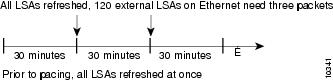
LSA Group Pacing with Multiple Timers
Configuring each LSA to have its own timer avoids excessive CPU processing and sudden network-traffic increase. To again
use the example of refreshing, each LSA gets refreshed when it is 30 minutes old, independent of other LSAs. So the CPU is
used only when necessary. However, LSAs being refreshed at frequent, random intervals would require many packets for the few
refreshed LSAs that the router must send, which would be inefficient use of bandwidth.
Therefore, the router delays the LSA refresh function for an interval of time instead of performing it when the individual
timers are reached. The accumulated LSAs constitute a group, which is then refreshed and sent out in one packet or more. Thus,
the refresh packets are paced, as are the checksumming and aging. The pacing interval is configurable; it defaults to 4 minutes,
which is randomized to further avoid synchronization.
The figure below illustrates the case of refresh packets. The first timeline illustrates individual LSA timers; the second
timeline illustrates individual LSA timers with group pacing.
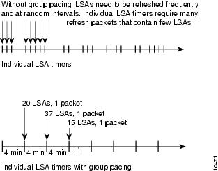
The group pacing interval is inversely proportional to the number of LSAs that the router is refreshing, checksumming, and
aging. For example, if you have approximately 10,000 LSAs, decreasing the pacing interval would benefit you. If you have a
very small database (40 to 100 LSAs), increasing the pacing interval to 10 to 20 minutes might benefit you slightly.
The default value of pacing between LSA groups is 240 seconds (4 minutes). The range is from 10 seconds to 1800 seconds (30
minutes).
By default, OSPF floods new LSAs over all interfaces in the same area, except the interface on which the LSA arrives. Some
redundancy is desirable, because it ensures robust flooding. However, too much redundancy can waste bandwidth and might destabilize
the network due to excessive link and CPU usage in certain topologies. An example would be a fully meshed topology.
You can block OSPF flooding of LSAs in two ways, depending on the type of networks:
-
On broadcast, nonbroadcast, and point-to-point networks, you can block flooding over specified OSPF interfaces.
-
On point-to-multipoint networks, you can block flooding to a specified neighbor.
The growth of the Internet has increased the importance of scalability in IGPs such as OSPF. By design, OSPF requires LSAs
to be refreshed as they expire after 3600 seconds. Some implementations have tried to improve the flooding by reducing the
frequency to refresh from 30 minutes to about 50 minutes. This solution reduces the amount of refresh traffic but requires
at least one refresh before the LSA expires. The OSPF flooding reduction solution works by reducing unnecessary refreshing
and flooding of already known and unchanged information. To achieve this reduction, the LSAs are now flooded with the higher
bit set. The LSAs are now set as “do not age.”
Cisco routers do not support LSA Type 6 Multicast OSPF (MOSPF), and they generate syslog messages if they receive such packets.
If the router is receiving many MOSPF packets, you might want to configure the router to ignore the packets and thus prevent
a large number of syslog messages.
The former OSPF implementation for sending update packets needed to be more efficient. Some update packets were getting lost
in cases where the link was slow, a neighbor could not receive the updates quickly enough, or the router was out of buffer
space. For example, packets might be dropped if either of the following topologies existed:
-
A fast router was connected to a slower router over a point-to-point link.
-
During flooding, several neighbors sent updates to a single router at the same time.
OSPF update packets are now automatically paced so they are not sent less than 33 milliseconds apart. Pacing is also added
between resends to increase efficiency and minimize lost retransmissions. Also, you can display the LSAs waiting to be sent
out an interface. The benefit of pacing is that OSPF update and retransmission packets are sent more efficiently. There are
no configuration tasks for this feature; it occurs automatically.
You can display specific statistics such as the contents of IP routing tables, caches, and databases. Information provided
can be used to determine resource utilization and solve network problems. You can also display information about node reachability
and discover the routing path that your device packets are taking through the network.
How to Configure OSPF
To configure OSPF, perform the tasks described in the following sections. The tasks in the “Enabling OSPF” section are required;
the tasks in the remaining sections are optional, but might be required for your application. For information about the maximum
number of interfaces, see the “Restrictions for OSPF” section.
Enabling OSPF
SUMMARY STEPS
-
enable
-
configure
terminal
-
router ospf
process-id -
network
ip-address
wildcard-mask
area
area-id -
end
DETAILED STEPS
| Command or Action | Purpose | |
|---|---|---|
|
Step 1 |
Example: |
Enables privileged EXEC mode.
|
|
Step 2 |
Example: |
Enters global configuration mode. |
|
Step 3 |
router ospf Example: |
Enables OSPF routing and enters router configuration mode. |
|
Step 4 |
network Example: |
Defines an interface on which OSPF runs and defines the area ID for that interface. |
|
Step 5 |
Example: |
Exits router configuration mode and returns to privileged EXEC mode. |
Configuring OSPF Interface
Parameters
SUMMARY STEPS
-
enable -
configure
terminal
-
interface
type
number -
ip
ospf
cost
cost
-
ip
ospf
retransmit-interval
seconds
-
ip
ospf
transmit-delay
seconds
-
ip
ospf
priority
number-value
-
ip
ospf
hello-interval
seconds
-
ip
ospf
dead-interval
seconds
-
ip
ospf
authentication-key
key
-
ip
ospf
message-digest-key
key-id
md5
key
-
ip
ospf
authentication
[message-digest |
null ] -
end
DETAILED STEPS
| Command or Action | Purpose | |
|---|---|---|
|
Step 1 |
Example: |
Enables
|
|
Step 2 |
Example: |
Enters global |
|
Step 3 |
interface Example: |
Configures an |
|
Step 4 |
Example: |
Explicitly |
|
Step 5 |
Example: |
Specifies the |
|
Step 6 |
Example: |
Sets the |
|
Step 7 |
Example: |
Sets priority |
|
Step 8 |
Example: |
Specifies the |
|
Step 9 |
Example: |
Sets the |
|
Step 10 |
Example: |
Assigns a |
|
Step 11 |
Example: |
Enables OSPF |
|
Step 12 |
Example: |
Specifies the |
|
Step 13 |
Example: |
Exits |
Configuring OSPF over Different Physical Networks
Configuring OSPF for Point-to-Multipoint Broadcast Networks
SUMMARY STEPS
-
configure
terminal
-
interface
type
number
-
ip
ospf
network
point-to-multipoint - exit
-
router
ospf
process-id - neighbor
ip-address
[cost
number]
DETAILED STEPS
| Command or Action | Purpose | |||
|---|---|---|---|---|
|
Step 1 |
Example: |
Enters global configuration mode. |
||
|
Step 2 |
Example: |
Specifies an interface type and number, and enters interface configuration mode. |
||
|
Step 3 |
ip Example: |
Configures an interface as point-to-multipoint for broadcast media. |
||
|
Step 4 |
exit Example: |
Enters global configuration mode. |
||
|
Step 5 |
router Example: |
Configures an OSPF routing process and enters router configuration mode. |
||
|
Step 6 |
neighbor Example: |
Specifies a neighbor and assigns a cost to the neighbor.
|
Configuring OSPF for Nonbroadcast Networks
SUMMARY STEPS
-
configure
terminal
-
interface
type
number
-
ip
ospf
network
point-to-multipoint
non-broadcast - exit
-
router
ospf
process-id - neighbor
ip-address
[cost
number]
DETAILED STEPS
| Command or Action | Purpose | |||
|---|---|---|---|---|
|
Step 1 |
Example: |
Enters global configuration mode. |
||
|
Step 2 |
Example: |
Specifies an interface type and number, and enters interface configuration mode. |
||
|
Step 3 |
ip Example: |
Configures an interface as point-to-multipoint for nonbroadcast media. |
||
|
Step 4 |
exit Example: |
Enters global configuration mode. |
||
|
Step 5 |
router Example: |
Configures an OSPF routing process and enters router configuration mode. |
||
|
Step 6 |
neighbor Example: |
Specifies a neighbor and assigns a cost to the neighbor.
|
Configuring OSPF Area
Parameters
SUMMARY STEPS
-
enable -
configure
terminal
-
routerospf
process-id
-
area
area-id
authentication
-
area
area-id
stub
[no summary ] -
area
area-id
default-cost
cost
-
end
DETAILED STEPS
| Command or Action | Purpose | |
|---|---|---|
|
Step 1 |
Example: |
Enables
|
|
Step 2 |
Example: |
Enters global |
|
Step 3 |
ospf process-id Example: |
Enables OSPF |
|
Step 4 |
Example: |
Enables |
|
Step 5 |
Example: |
Defines an area |
|
Step 6 |
Example: |
Specifies a |
|
Step 7 |
Example: |
Exits router |
Configuring OSPFv2 NSSA
Configuring an OSPFv2 NSSA
Area and Its Parameters
SUMMARY STEPS
-
enable -
configure
terminal -
routerospf
process-id
-
redistribute
protocol
[process-id ]
{level-1 |
level-1-2 |
level-2 }
[autonomous-system-number ]
[metric {metric-value |
transparent }]
[metric-type
type-value ]
[match {internal |
external
1 |
external
2 }] [tag
tag-value ]
[route-map
map-tag ]
[subnets ]
[nssa-only ] -
network
ip-address
wildcard-mask
area
area-id -
area
area-id
nssa
[no-redistribution ] [default-information-originate [metric ] [metric-type ]] [no-summary ] [nssa-only ] -
summary-address
prefix mask
[not-advertise ] [tag tag ] [nssa-only ] -
end
DETAILED STEPS
| Command or Action | Purpose | |
|---|---|---|
|
Step 1 |
Example: |
Enables
|
|
Step 2 |
Example: |
Enters global |
|
Step 3 |
ospf Example: |
Enables OSPF
|
|
Step 4 |
Example: |
Redistributes
|
|
Step 5 |
Example: |
Defines the |
|
Step 6 |
[no-redistribution ] [default-information-originate [metric ] [metric-type ]] [no-summary ] [nssa-only ] Example: |
Configures a |
|
Step 7 |
summary-address Example: |
Controls the |
|
Step 8 |
Example: |
Exits router |
Configuring an NSSA ABR as a
Forced NSSA LSA Translator
SUMMARY STEPS
-
enable -
configure
terminal
-
router
ospf
process-id
-
area
area-id
nssa
translate type7
always -
area
area-id
nssa
translate type7
suppress-fa
-
end
DETAILED STEPS
| Command or Action | Purpose | |||
|---|---|---|---|---|
|
Step 1 |
Example: |
Enables
|
||
|
Step 2 |
Example: |
Enters global |
||
|
Step 3 |
ospf Example: |
Enables OSPF
|
||
|
Step 4 |
Example: |
Configures a
|
||
|
Step 5 |
Example: |
Allows ABR to |
||
|
Step 6 |
Example: |
Exits router |
Disabling RFC 3101
Compatibility and Enabling RFC 1587 Compatibility
SUMMARY STEPS
-
enable -
configure
terminal
-
router
ospf
process-id
-
compatible
rfc1587
-
end
DETAILED STEPS
| Command or Action | Purpose | |
|---|---|---|
|
Step 1 |
Example: |
Enables
|
|
Step 2 |
Example: |
Enters global |
|
Step 3 |
ospf Example: |
Enables OSPF
|
|
Step 4 |
Example: |
Enables the device to be RFC 1587 compliant. |
|
Step 5 |
Example: |
Exits router |
Configuring OSPF NSSA Parameters
Prerequisites
Evaluate the
following considerations before you implement this feature:
-
You can set a
Type 7 default route that can be used to reach external destinations. When
configured, the device generates a Type 7 default into the Not-So-Stubby Area
(NSSA or the NSSA Area Border Router (ABR). -
Every device
within the same area must agree that the area is NSSA; otherwise, the devices
cannot communicate.
Configuring Route Summarization Between OSPF Areas
Configuring Route Summarization When Redistributing Routes into OSPF
SUMMARY STEPS
-
summary-address {ip-address
mask
|
prefix
mask }
[not-advertise ][tag
tag [nssa-only]
DETAILED STEPS
| Command or Action | Purpose |
|---|---|
|
summary-address {ip-address Example: |
|
Establishing Virtual Links
SUMMARY STEPS
-
area
area-id
virtual-link
router-id [authentication
[message-digest
|
null ]]
[hello-interval
seconds ] [retransmit-interval
seconds ] [transmit-delay
seconds ] [dead-interval
seconds ] [authentication-key
key |
message-digest-key
key-id
md5
key ]
DETAILED STEPS
| Command or Action | Purpose |
|---|---|
|
area Example: |
Establishes a virtual link. |
Generating a Default Route
SUMMARY STEPS
-
enable
-
configure
terminal
-
router ospf
process-id -
default-information
originate [always ] [metric
metric-value ] [metric-type
type-value ] [route-map
map-name ] -
end
DETAILED STEPS
| Command or Action | Purpose | |||
|---|---|---|---|---|
|
Step 1 |
Example: |
Enables privileged EXEC mode.
|
||
|
Step 2 |
Example: |
Enters global configuration mode. |
||
|
Step 3 |
router ospf Example: |
Enables OSPF routing and enters router configuration mode. |
||
|
Step 4 |
default-information Example: |
Forces the ASBR to generate a default route into the OSPF routing domain.
|
||
|
Step 5 |
Example: |
Exits router configuration mode and returns to privileged EXEC mode. |
Configuring Lookup of DNS Names
SUMMARY STEPS
-
enable
-
configure
terminal
-
ip
ospf
name-lookup -
end
DETAILED STEPS
| Command or Action | Purpose | |
|---|---|---|
|
Step 1 |
Example: |
Enables privileged EXEC mode.
|
|
Step 2 |
Example: |
Enters global configuration mode. |
|
Step 3 |
ip Example: |
Enables OSPF routing and enters router configuration mode. |
|
Step 4 |
Example: |
Exits global configuration mode and returns to privileged EXEC mode. |
Forcing the Router ID Choice with a Loopback Interface
SUMMARY STEPS
-
configure
terminal
-
interface
type
number
-
ip
address
ip-address
mask
DETAILED STEPS
| Command or Action | Purpose | |
|---|---|---|
|
Step 1 |
Example: |
Enters global configuration mode. |
|
Step 2 |
Example: |
Creates a loopback interface and enters interface configuration mode. |
|
Step 3 |
ip Example: |
Assigns an IP address to this interface. |
Controlling Default
Metrics
SUMMARY STEPS
-
enable -
configure
terminal
-
router ospf
process-id -
auto-cost
reference-bandwidth
ref-bw
-
end
DETAILED STEPS
| Command or Action | Purpose | |
|---|---|---|
|
Step 1 |
Example: |
Enables
|
|
Step 2 |
Example: |
Enters global |
|
Step 3 |
router ospf Example: |
Enables OSPF |
|
Step 4 |
auto-cost Example: |
Differentiates |
|
Step 5 |
Example: |
Exits router |
Changing the OSPF Administrative Distances
SUMMARY STEPS
-
enable
-
configure
terminal
-
router ospf
process-id -
distance
ospf {intra-area |
inter-area |
external }
dist
-
end
DETAILED STEPS
| Command or Action | Purpose | |
|---|---|---|
|
Step 1 |
Example: |
Enables privileged EXEC mode.
|
|
Step 2 |
Example: |
Enters global configuration mode. |
|
Step 3 |
router ospf Example: |
Enables OSPF routing and enters router configuration mode. |
|
Step 4 |
distance Example: |
Changes the OSPF distance values. |
|
Step 5 |
Example: |
Exits router configuration mode and returns to privileged EXEC mode. |
Configuring OSPF on Simplex Ethernet Interfaces
|
Command |
Purpose |
|---|---|
|
Suppresses the sending of hello packets through the specified interface. |
Configuring Route Calculation Timers
SUMMARY STEPS
-
enable
-
configure
terminal
-
router ospf
process-id -
timers
throttle
spf
spf-start
spf-hold
spf-max-wait
-
end
DETAILED STEPS
| Command or Action | Purpose | |
|---|---|---|
|
Step 1 |
Example: |
Enables privileged EXEC mode.
|
|
Step 2 |
Example: |
Enters global configuration mode. |
|
Step 3 |
router ospf Example: |
Enables OSPF routing and enters router configuration mode. |
|
Step 4 |
timers Example: |
Configures route calculation timers. |
|
Step 5 |
Example: |
Exits router configuration mode and returns to privileged EXEC mode. |
Configuring OSPF over On-Demand Circuits
SUMMARY STEPS
-
router ospf
process-id -
interface
type number - ip ospf demand-circuit
DETAILED STEPS
| Command or Action | Purpose | |
|---|---|---|
|
Step 1 |
router ospf |
Enables OSPF operation. |
|
Step 2 |
interface |
Enters interface configuration mode. |
|
Step 3 |
ip ospf demand-circuit |
Configures OSPF over an on-demand circuit. |
What to do next
|
Note |
You can prevent an interface from accepting demand-circuit requests from other routers to by specifying the |
Prerequisites
Evaluate the following considerations before implementing the On-Demand Circuits feature:
-
Because LSAs that include topology changes are flooded over an on-demand circuit, we recommend that you put demand circuits
within OSPF stub areas or within NSSAs to isolate the demand circuits from as many topology changes as possible. -
Every router within a stub area or NSSA must have this feature loaded in order to take advantage of the on-demand circuit
functionality. If this feature is deployed within a regular area, all other regular areas must also support this feature before
the demand circuit functionality can take effect because Type 5 external LSAs are flooded throughout all areas. -
Hub-and-spoke network topologies that have a point-to-multipoint (P2MP) OSPF interface type on a hub might not revert to
nondemand circuit mode when needed. You must simultaneously reconfigure OSPF on all interfaces on the P2MP segment when reverting
them from demand circuit mode to nondemand circuit mode. -
Do not implement this feature on a broadcast-based network topology because the overhead protocols (such as hello and LSA
packets) cannot be successfully suppressed, which means the link will remain up. -
Configuring the router for an OSPF on-demand circuit with an asynchronous interface is not a supported configuration. The
supported configuration is to use dialer interfaces on both ends of the circuit. For more information, refer to
Why OSPF Demand Circuit Keeps Bringing Up the Link .
Logging Neighbors Going Up or Down
SUMMARY STEPS
-
enable
-
configure
terminal
-
router ospf
process-id - log-adjacency-changes [detail ]
-
end
DETAILED STEPS
| Command or Action | Purpose | |||
|---|---|---|---|---|
|
Step 1 |
Example: |
Enables privileged EXEC mode.
|
||
|
Step 2 |
Example: |
Enters global configuration mode. |
||
|
Step 3 |
router ospf Example: |
Enables OSPF routing and enters router configuration mode. |
||
|
Step 4 |
log-adjacency-changes [detail ] Example: |
|
||
|
Step 5 |
Example: |
Exits router configuration mode and returns to privileged EXEC mode. |
Changing the LSA Group Pacing Interval
SUMMARY STEPS
-
enable
-
configure
terminal
-
router ospf
process-id -
timers
pacing
lsa-group
seconds
-
end
DETAILED STEPS
| Command or Action | Purpose | |
|---|---|---|
|
Step 1 |
Example: |
Enables privileged EXEC mode.
|
|
Step 2 |
Example: |
Enters global configuration mode. |
|
Step 3 |
router ospf Example: |
Enables OSPF routing and enters router configuration mode. |
|
Step 4 |
timers Example: |
Changes the group pacing of LSAs. |
|
Step 5 |
Example: |
Exits router configuration mode and returns to privileged EXEC mode. |
Blocking OSPF LSA Flooding
|
Command |
Purpose |
|---|---|
|
Blocks the flooding of OSPF LSA packets to the interface. |
On point-to-multipoint networks, to block flooding of OSPF LSAs, use the following command in router configuration mode:
|
Command |
Purpose |
|---|---|
|
Blocks the flooding of OSPF LSA packets to the specified neighbor. |
Reducing LSA Flooding
|
Command |
Purpose |
|---|---|
|
Suppresses the unnecessary flooding of LSAs in stable topologies. |
Ignoring MOSPF LSA Packets
|
Command |
Purpose |
|---|---|
|
Prevents the router from generating syslog messages when it receives MOSPF LSA packets. |
Monitoring and Maintaining OSPF
|
Command |
Purpose |
|---|---|
|
Displays general information about OSPF routing processes. |
|
Displays the internal OSPF routing table entries to the ABR and ASBR. |
|
Displays lists of information related to the OSPF database. |
|
Displays a list of LSAs waiting to be flooded over an interface (to observe OSPF packet pacing). |
|
Displays OSPF-related interface information. |
|
Displays OSPF neighbor information on a per-interface basis. |
|
Displays a list of all LSAs requested by a router. |
|
Displays a list of all LSAs waiting to be re-sent. |
|
Displays a list of all summary address redistribution information configured under an OSPF process. |
|
Displays OSPF-related virtual links information. |
To restart an OSPF process, use the following command in EXEC mode:
|
Command |
Purpose |
|---|---|
|
Clears redistribution based on the OSPF routing process ID. If the |
Displaying OSPF Update Packet Pacing
SUMMARY STEPS
-
show
ip
ospf
flood-list
interface-type
interface-number
DETAILED STEPS
| Command or Action | Purpose |
|---|---|
|
show Example: |
Displays a list of OSPF LSAs waiting to be flooded over an interface. |
Restrictions for OSPF
On systems with a large number of interfaces, it may be possible to configure OSPF such that the number of links advertised
in the router LSA causes the link-state update packet to exceed the size of a “huge” Cisco buffer. To resolve this problem,
reduce the number of OSPF links or increase the huge buffer size by entering the
buffers
huge
size
size command.
A link-state update packet containing a router LSA typically has a fixed overhead of 196 bytes, and an additional 12 bytes
are required for each link description. With a huge buffer size of 18024 bytes, there can be a maximum of 1485 link descriptions.
Because the maximum size of an IP packet is 65,535 bytes, there is still an upper bound on the number of links possible on
a router.
Configuration Examples for OSPF
Example: OSPF Point-to-Multipoint
In the figure below, Router 1 uses data-link connection identifier (DLCI) 201 to communicate with Router 2, DLCI 202 to communicate
with Router 4, and DLCI 203 to communicate with Router 3. Router 2 uses DLCI 101 to communicate with Router 1 and DLCI 102
to communicate with Router 3. Router 3 communicates with Router 2 (DLCI 401) and Router 1 (DLCI 402). Router 4 communicates
with Router 1 (DLCI 301). Configuration examples follow the figure.

Router 1 Configuration
hostname Router 1
!
interface serial 1
 ip address 10.0.0.2 255.0.0.0
 ip ospf network point-to-multipoint
 encapsulation frame-relay
 frame-relay map ip 10.0.0.1 201 broadcast
 frame-relay map ip 10.0.0.3 202 broadcast
 frame-relay map ip 10.0.0.4 203 broadcast
!
router ospf 1
 network 10.0.0.0 0.0.0.255 area 0
Router 2 Configuration
hostname Router 2
!
interface serial 0
 ip address 10.0.0.1 255.0.0.0
 ip ospf network point-to-multipoint
 encapsulation frame-relay
 frame-relay map ip 10.0.0.2 101 broadcast
 frame-relay map ip 10.0.0.4 102 broadcast
!
router ospf 1
 network 10.0.0.0 0.0.0.255 area 0
Router 3 Configuration
hostname Router 3
!
interface serial 3
 ip address 10.0.0.4 255.0.0.0
 ip ospf network point-to-multipoint
 encapsulation frame-relay
 clock rate 1000000
 frame-relay map ip 10.0.0.1 401 broadcast
 frame-relay map ip 10.0.0.2 402 broadcast
!
router ospf 1
 network 10.0.0.0 0.0.0.255 area 0
Router 4 Configuration
hostname Router 4
!
interface serial 2
 ip address 10.0.0.3 255.0.0.0
 ip ospf network point-to-multipoint
 encapsulation frame-relay
 clock rate 2000000
 frame-relay map ip 10.0.0.2 301 broadcast
!
router ospf 1
 network 10.0.0.0 0.0.0.255 area 0
Example: OSPF
Point-to-Multipoint with Broadcast
The following
example illustrates a point-to-multipoint network with broadcast:
interface Serial0
 ip address 10.0.1.1 255.255.255.0
 encapsulation frame-relay
 ip ospf cost 100
 ip ospf network point-to-multipoint
 frame-relay map ip 10.0.1.3 202 broadcast
 frame-relay map ip 10.0.1.4 203 broadcast
 frame-relay map ip 10.0.1.5 204 broadcast
 frame-relay local-dlci 200
!
router ospf 1
 network 10.0.1.0 0.0.0.255 area 0
 neighbor 10.0.1.5 cost 5
 neighbor 10.0.1.4 cost 10
The following
example shows the configuration of the neighbor at 10.0.1.3:
interface serial 0
 ip address 10.0.1.3 255.255.255.0
 ip ospf network point-to-multipoint
 encapsulation frame-relay
 frame-relay local-dlci 301
 frame-relay map ip 10.0.1.1 300 broadcast
 no shutdown
!
 router ospf 1
 network 10.0.1.0 0.0.0.255 area 0
The output shown
for neighbors in the first configuration is as follows:
Device# show ip ospf neighbor
Neighbor ID     Pri   State           Dead Time   Address         Interface
172.16.1.1           1   FULL/  -        00:01:50    10.0.1.5        Serial0
172.16.1.4           1   FULL/  -        00:01:47    10.0.1.4        Serial0
172.16.1.8           1   FULL/  -        00:01:45    10.0.1.3        Serial0
The route
information in the first configuration is as follows:
Device# show ip route
Codes: C - connected, S - static, I - IGRP, R - RIP, M - mobile, B - BGP
       D - EIGRP, EX - EIGRP external, O - OSPF, IA - OSPF inter area
       N1 - OSPF NSSA external type 1, N2 - OSPF NSSA external type 2
       E1 - OSPF external type 1, E2 - OSPF external type 2, E - EGP
       i - IS-IS, L1 - IS-IS level-1, L2 - IS-IS level-2, * - candidate default
       U - per-user static route, o - ODR
Gateway of last resort is not set
C    1.0.0.0/8 is directly connected, Loopback0
     10.0.0.0/8 is variably subnetted, 4 subnets, 2 masks
O       10.0.1.3/32 [110/100] via 10.0.1.3, 00:39:08, Serial0
C       10.0.1.0/24 is directly connected, Serial0
O       10.0.1.5/32 [110/5] via 10.0.1.5, 00:39:08, Serial0
O       10.0.1.4/32 [110/10] via 10.0.1.4, 00:39:08, Serial0
Example: OSPF
Point-to-Multipoint with Nonbroadcast
The following
example illustrates a point-to-multipoint network with nonbroadcast:
interface Serial0
 ip address 10.0.1.1 255.255.255.0
 ip ospf network point-to-multipoint non-broadcast
 encapsulation frame-relay
 no keepalive
 frame-relay local-dlci 200
 frame-relay map ip 10.0.1.3 202
 frame-relay map ip 10.0.1.4 203
 frame-relay map ip 10.0.1.5 204
 no shutdown
 !
 router ospf 1
  network 10.0.1.0 0.0.0.255 area 0
  neighbor 10.0.1.3 cost 5
  neighbor 10.0.1.4 cost 10
  neighbor 10.0.1.5 cost 15
The following
example is the configuration for the router on the other side:
interface Serial9/2
 ip address 10.0.1.3 255.255.255.0
 encapsulation frame-relay
 ip ospf network point-to-multipoint non-broadcast
 no ip mroute-cache
 no keepalive
 no fair-queue
 frame-relay local-dlci 301
 frame-relay map ip 10.0.1.1 300
 no shutdown
 !
 router ospf 1
  network 10.0.1.0 0.0.0.255 area 0
The output shown
for neighbors in the first configuration is as follows:
Device# show ip ospf neighbor

Neighbor ID     Pri   State           Dead Time   Address         Interface
172.16.1.1           1   FULL/  -        00:01:52    10.0.1.5        Serial0
172.16.1.4           1   FULL/  -        00:01:52    10.0.1.4        Serial0
172.16.1.8           1   FULL/  -        00:01:52    10.0.1.3        Serial0
Example: Variable-Length Subnet Masks
OSPF, static routes, and IS-IS support variable-length subnet masks (VLSMs). With VLSMs, you can use different masks for
the same network number on different interfaces, which allows you to conserve IP addresses and more efficiently use available
address space.
In the following example, a 30-bit subnet mask is used, leaving two bits of address space reserved for serial-line host addresses.
There is sufficient host address space for two host endpoints on a point-to-point serial link.
interface ethernet 0
 ip address 172.16.10.1 255.255.255.0
! 8 bits of host address space reserved for ethernets
interface serial 0
 ip address 172.16.20.1 255.255.255.252
! 2 bits of address space reserved for serial lines
! Router is configured for OSPF and assigned AS 107
router ospf 107
! Specifies network directly connected to the router
 network 172.16.0.0 0.0.255.255 area 0.0.0.0
Example: Configuring OSPF NSSA
In the following
example, an Open Shortest Path First (OSPF) stub network is configured to
include OSPF Area 0 and OSPF Area 1, using five devices. Device 3 is configured as the NSSA
Autonomous System Border Router (ASBR). Device 2 configured to be the NSSA
Area Border Router (ABR). OSPF Area 1 is defined
as a Not-So-Stubby Area (NSSA).
Device 1
hostname Device1
!
interface Loopback1
 ip address 10.1.0.1 255.255.255.255
!
interface Ethernet0/0
 ip address 192.168.0.1 255.255.255.0
 ip ospf 1 area 0
 no cdp enable
!
interface Serial10/0
 description Device2 interface s11/0
 ip address 192.168.10.1 255.255.255.0
 ip ospf 1 area 1
 serial restart-delay 0
 no cdp enable
!
router ospf 1
 area 1 nssa
!
end
Device 2
hostname Device2
!
!
interface Loopback1
 ip address 10.1.0.2 255.255.255.255
!
interface Serial10/0
 description Device1 interface s11/0
 no ip address
 shutdown
 serial restart-delay 0
 no cdp enable
!
interface Serial11/0
 description Device1 interface s10/0
 ip address 192.168.10.2 255.255.255.0
 ip ospf 1 area 1
 serial restart-delay 0
 no cdp enable
!
interface Serial14/0
 description Device3 interface s13/0
 ip address 192.168.14.2 255.255.255.0
 ip ospf 1 area 1
 serial restart-delay 0
 no cdp enable
!
router ospf 1
 area 1 nssa
!
end
Device 3
hostname Device3
!
interface Loopback1
 ip address 10.1.0.3 255.255.255.255
!
interface Ethernet3/0
 ip address 192.168.3.3 255.255.255.0
 no cdp enable
!
interface Serial13/0
 description Device2 interface s14/0
 ip address 192.168.14.3 255.255.255.0
 ip ospf 1 area 1
 serial restart-delay 0
 no cdp enable
!
router ospf 1
 log-adjacency-changes
 area 1 nssa
 redistribute rip subnets
!
router rip
 version 2
 redistribute ospf 1 metric 15
 network 192.168.3.0
end
Device 4
hostname Device4
!
interface Loopback1
 ip address 10.1.0.4 255.255.255.255
!
interface Ethernet3/0
 ip address 192.168.3.4 255.255.255.0
 no cdp enable
!
interface Ethernet4/1
 ip address 192.168.41.4 255.255.255.0
!
router rip
 version 2
 network 192.168.3.0
 network 192.168.41.0
!
end
Device 5
hostname Device5
!
interface Loopback1
 ip address 10.1.0.5 255.255.255.255
!
interface Ethernet0/0
 ip address 192.168.0.10 255.255.255.0
 ip ospf 1 area 0
 no cdp enable
!
interface Ethernet1/1
 ip address 192.168.11.10 255.255.255.0
 ip ospf 1 area 0
!
router ospf 1
!
end
Example: OSPF NSSA Area with
RFC 3101 Disabled and RFC 1587 Active
In the following
example, the output for the
show
ip
ospf and
show
ip
ospf
database
nssa commands shows an Open Shortest Path First
Not-So-Stubby Area (OSPF NSSA) area where RFC 3101 is disabled, RFC 1587 is
active, and an NSSA Area Border Router (ABR) device is configured as a forced
NSSA LSA translator. If RFC 3101 is disabled, the forced NSSA LSA translator
remains inactive.
Device# show ip ospf

Routing Process "ospf 1" with ID 10.0.2.1
Start time: 00:00:25.512, Time elapsed: 00:01:02.200
Supports only single TOS(TOS0) routes
Supports opaque LSA
Supports Link-local Signaling (LLS)
Supports area transit capability
Supports NSSA (compatible with RFC 1587)
Event-log enabled, Maximum number of events: 1000, Mode: cyclic
Router is not originating router-LSAs with maximum metric
Initial SPF schedule delay 5000 msecs
Minimum hold time between two consecutive SPFs 10000 msecs
Maximum wait time between two consecutive SPFs 10000 msecs
Incremental-SPF disabled
Minimum LSA interval 5 secs
Minimum LSA arrival 1000 msecs
LSA group pacing timer 240 secs
Interface flood pacing timer 33 msecs
Retransmission pacing timer 66 msecs
Number of external LSA 0. Checksum Sum 0x000000
Number of opaque AS LSA 0. Checksum Sum 0x000000
Number of DCbitless external and opaque AS LSA 0
Number of DoNotAge external and opaque AS LSA 0
Number of areas in this router is 1. 0 normal 0 stub 1 nssa
Number of areas transit capable is 0
External flood list length 0
IETF NSF helper support enabled
Cisco NSF helper support enabled
Reference bandwidth unit is 100 mbps
Area 1
Number of interfaces in this area is 1
It is a NSSA area
Configured to translate Type-7 LSAs, inactive (RFC3101 support
disabled)
Area has no authentication
SPF algorithm last executed 00:00:07.160 ago
SPF algorithm executed 3 times
Area ranges are
Number of LSA 3. Checksum Sum 0x0245F0
Number of opaque link LSA 0. Checksum Sum 0x000000
Number of DCbitless LSA 0
Number of indication LSA 0
Number of DoNotAge LSA 0
Flood list length 0
The table below describes the
show
ip
ospf display fields and their descriptions.
|
Field |
Description |
|---|---|
|
Supports NSSA |
Specifies that RFC 1587 is |
|
Configured to |
Specifies that OSPF NSSA area has an ABR device configured to act as a forced translator |
Device2# show ip ospf database nssa

Router Link States (Area 1)
LS age: 28
Options: (No TOS-capability, DC)
LS Type: Router Links
Link State ID: 10.0.2.1
Advertising Router: 10.0.2.1
LS Seq Number: 80000004
Checksum: 0x5CA2
Length: 36
Area Border Router
AS Boundary Router
Unconditional NSSA translator
Number of Links: 1
Link connected to: a Stub Network
(Link ID) Network/subnet number: 192.0.2.5
(Link Data) Network Mask: 255.255.255.0
Number of MTID metrics: 0
TOS 0 Metrics: 10
The table below describes the
show
ip
ospf database nssa display fields and their descriptions.
|
Field |
Description |
|---|---|
|
Unconditional |
Specifies that NSSA ASBR device is a forced NSSA LSA |
Example: OSPF Routing and Route Redistribution
OSPF typically requires coordination among many internal routers, ABRs, and ASBRs. At a minimum, OSPF-based routers can be
configured with all default parameter values, with no authentication, and with interfaces assigned to areas.
Three types of examples follow:
-
The first is a simple configuration illustrating basic OSPF commands.
-
The second example illustrates a configuration for an internal router, ABR, and ASBRs within a single, arbitrarily assigned,
OSPF autonomous system. -
The third example illustrates a more complex configuration and the application of various tools available for controlling
OSPF-based routing environments.
Example: Basic OSPF Configuration
The following example illustrates a simple OSPF configuration that enables OSPF routing process 9000, attaches Ethernet interface
0 to area 0.0.0.0, and redistributes RIP into OSPF and OSPF into RIP:
interface ethernet 0
 ip address 10.93.1.1 255.255.255.0
 ip ospf cost 1
!
interface ethernet 1
 ip address 10.94.1.1 255.255.255.0
!
router ospf 9000
 network 10.93.0.0 0.0.255.255 area 0.0.0.0
 redistribute rip metric 1 subnets
!
router rip
 network 10.94.0.0
 redistribute ospf 9000
 default-metric 1
Example: Basic OSPF Configuration for Internal Router ABR and ASBRs
The following example illustrates the assignment of four area IDs to four IP address ranges. In the example, OSPF routing
process 109 is initialized, and four OSPF areas are defined: 10.9.50.0, 2, 3, and 0. Areas 10.9.50.0, 2, and 3 mask specific
address ranges, and area 0 enables OSPF for
all
other networks.
router ospf 109
 network 192.168.10.0 0.0.0.255 area 10.9.50.0
 network 192.168.20.0 0.0.255.255 area 2
 network 192.168.30.0 0.0.0.255 area 3
 network 192.168.40.0 255.255.255.255 area 0
!
! Interface Ethernet0 is in area 10.9.50.0:
interface ethernet 0
 ip address 192.168.10.5 255.255.255.0
!
! Interface Ethernet1 is in area 2:
interface ethernet 1
 ip address 192.168.20.5 255.255.255.0
!
! Interface Ethernet2 is in area 2:
interface ethernet 2
 ip address 192.168.20.7 255.255.255.0
!
! Interface Ethernet3 is in area 3:
interface ethernet 3
 ip address 192.169.30.5 255.255.255.0
!
! Interface Ethernet4 is in area 0:
interface ethernet 4
 ip address 192.168.40.1 255.255.255.0
!
! Interface Ethernet5 is in area 0:
interface ethernet 5
 ip address 192.168.40.12 255.255.0.0
Each
network
area router configuration command is evaluated sequentially, so the order of these commands in the configuration is important.
The Cisco software sequentially evaluates the address/wildcard-mask pair for each interface. See the
network
area command page in the
Cisco IOS IP Routing: OSPF Command Reference for more information.
Consider the first
network
area command. Area ID 10.9.50.0 is configured for the interface on which subnet 192.168.10.0 is located. Assume that a match is
determined for Ethernet interface 0. Ethernet interface 0 is attached to area 10.9.50.0 only.
The second
network
area command is evaluated next. For area 2, the same process is then applied to all interfaces (except Ethernet interface 0).
Assume that a match is determined for Ethernet interface 1. OSPF is then enabled for that interface, and Ethernet interface
1 is attached to area 2.
This process of attaching interfaces to OSPF areas continues for all
network
area commands. Note that the last
network
area command in this example is a special case. With this command, all available interfaces (not explicitly attached to another
area) are attached to area 0.
Example: Complex Internal Router with ABR and ASBR
The following example outlines a configuration for several routers within a single OSPF autonomous system. The figure below
provides a general network map that illustrates this sample configuration.
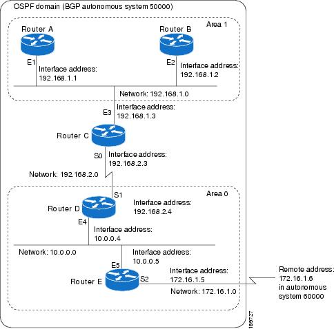
In this configuration, five routers are configured with OSPF:
-
Router A and Router B are both internal routers within area 1.
-
Router C is an OSPF ABR. Note that for Router C, Area 1 is assigned to E3 and area 0 is assigned to S0.
-
Router D is an internal router in area 0 (backbone area). In this case, both
network router configuration commands specify the same area (area 0, or the backbone area). -
Router E is an OSPF ASBR. Note that BGP routes are redistributed into OSPF and that these routes are advertised by OSPF.
|
Note |
You do not need to include definitions of all areas in an OSPF autonomous system in the configuration of all routers in the |
The OSPF domain in BGP autonomous system 109 is connected to the outside world via the BGP link to the external peer at IP
address 10.0.0.6. Sample configurations follow.
Following is the sample configuration for the general network map shown in the figure above.
Router A Configuration—Internal Router
interface ethernet 1
 ip address 192.168.1.1 255.255.255.0
router ospf 1
 network 192.168.0.0 0.0.255.255 area 1
Router B Configuration—Internal Router
interface ethernet 2
 ip address 192.168.1.2 255.255.255.0
router ospf 202
 network 192.168.0.0 0.0.255.255 area 1
Router C Configuration—ABR
interface ethernet 3
 ip address 192.168.1.3 255.255.255.0
interface serial 0
 ip address 192.168.2.3 255.255.255.0
router ospf 999
 network 192.168.1.0 0.0.0.255 area 1
 network 192.168.2.0 0.0.0.255 area 0
Router D Configuration—Internal Router
interface ethernet 4
 ip address 10.0.0.4 255.0.0.0
interface serial 1
 ip address 192.168.2.4 255.255.255.0
router ospf 50
 network 192.168.2.0 0.0.0.255 area 0
 network 10.0.0.0 0.255.255.255 area 0
Router E Configuration—ASBR
interface ethernet 5
 ip address 10.0.0.5 255.0.0.0
interface serial 2
 ip address 172.16.1.5 255.255.255.0
router ospf 65001
 network 10.0.0.0 0.255.255.255 area 0
 redistribute bgp 109 metric 1 metric-type 1
router bgp 109
 network 192.168.0.0
 network 10.0.0.0
 neighbor 172.16.1.6 remote-as 110
Example: Complex OSPF Configuration for ABR
The following sample configuration accomplishes several tasks in setting up an ABR. These tasks can be split into two general
categories:
-
Basic OSPF configuration
-
Route redistribution
The specific tasks outlined in this configuration are detailed briefly in the following descriptions. The figure below illustrates
the network address ranges and area assignments for the interfaces.
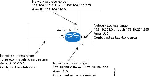
The basic configuration tasks in this example are as follows:
-
Configure address ranges for Ethernet interface 0 through Ethernet interface 3.
-
Enable OSPF on each interface.
-
Set up an OSPF authentication password for each area and network.
-
Assign link-state metrics and other OSPF interface configuration options.
-
Create a
stub
area with area ID 36.0.0.0. (Note that the
authentication and
stub options of the
area router configuration command are specified with separate
area command entries, but can be merged into a single
area command.) -
Specify the backbone area (area 0).
Configuration tasks associated with redistribution are as follows:
-
Redistribute IGRP and RIP into OSPF with various options set (including including
metric-type ,
metric ,
tag , and
subnet ). -
Redistribute IGRP and OSPF into RIP.
The following is a sample OSPF configuration:
interface ethernet 0
 ip address 192.0.2.201 255.255.255.0
 ip ospf authentication-key abcdefgh
 ip ospf cost 10
!
interface ethernet 1
 ip address 172.19.251.202 255.255.255.0
 ip ospf authentication-key ijklmnop
 ip ospf cost 20
 ip ospf retransmit-interval 10
 ip ospf transmit-delay 2
 ip ospf priority 4
!
interface ethernet 2
 ip address 172.19.254.2 255.255.255.0
 ip ospf authentication-key abcdefgh
 ip ospf cost 10
!
interface ethernet 3
 ip address 10.56.0.0 255.255.0.0
 ip ospf authentication-key ijklmnop
 ip ospf cost 20
 ip ospf dead-interval 80
In the following configuration, OSPF is on network 172.16.0.0:
router ospf 201
 network 10.10.0.0 0.255.255.255 area 10.10.0.0
 network 192.42.110.0 0.0.0.255 area 192.42.110.0
 network 172.16.0.0 0.0.255.255 area 0
 area 0 authentication
 area 10.10.0.0 stub
 area 10.10.0.0 authentication
 area 10.10.0.0 default-cost 20
 area 192.42.110.0 authentication
 area 10.10.0.0 range 10.10.0.0 255.0.0.0
 area 192.42.110.0 range 192.42.110.0 255.255.255.0
 area 0 range 172.16.251.0 255.255.255.0
 area 0 range 172.16.254.0 255.255.255.0
 redistribute igrp 200 metric-type 2 metric 1 tag 200 subnets
 redistribute rip metric-type 2 metric 1 tag 200
In the following configuration, IGRP autonomous system 200 is on 192.0.2.1:
router igrp 200
 network 172.31.0.0
!
! RIP for 192.168.110
!
router rip
 network 192.168.110.0
 redistribute igrp 200 metric 1
 redistribute ospf 201 metric 1
Examples: Route Map
The examples in this section illustrate the use of redistribution, with and without route maps. Examples from the IP and
Connectionless Network Service (CLNS) routing protocols are given.
The following example redistributes all OSPF routes into IGRP:
router igrp 109
 redistribute ospf 110
The following example redistributes RIP routes with a hop count equal to 1 into OSPF. These routes will be redistributed
into OSPF as external LSAs with a metric of 5, a metric type of Type 1, and a tag equal to 1.
router ospf 109
 redistribute rip route-map rip-to-ospf
!
route-map rip-to-ospf permit
 match metric 1
 set metric 5
 set metric-type type1
 set tag 1
The following example redistributes OSPF learned routes with tag 7 as a RIP metric of 15:
router rip
 redistribute ospf 109 route-map 5
!
route-map 5 permit
 match tag 7
 set metric 15
The following example redistributes OSPF intra-area and interarea routes with next-hop routers on serial interface 0 into
BGP with an INTER_AS metric of 5:
router bgp 109
 redistribute ospf 109 route-map 10
!
route-map 10 permit
 match route-type internal
 match interface serial 0
 set metric 5
The following example redistributes two types of routes into the integrated IS-IS routing table (supporting both IP and CLNS).
The first type is OSPF external IP routes with tag 5; these routes are inserted into Level 2 IS-IS link state packets (LSPs)
with a metric of 5. The second type is ISO-IGRP derived CLNS prefix routes that match CLNS access list 2000; these routes
will be redistributed into IS-IS as Level 2 LSPs with a metric of 30.
router isis
 redistribute ospf 109 route-map 2
 redistribute iso-igrp nsfnet route-map 3
!
route-map 2 permit
 match route-type external
 match tag 5
 set metric 5
 set level level-2
!
route-map 3 permit
 match address 2000
 set metric 30
With the following configuration, OSPF external routes with tags 1, 2, 3, and 5 are redistributed into RIP with metrics of
1, 1, 5, and 5, respectively. The OSPF routes with a tag of 4 are not redistributed.
router rip
 redistribute ospf 109 route-map 1
!
route-map 1 permit
 match tag 1 2
 set metric 1
!
route-map 1 permit
 match tag 3
 set metric 5
!
route-map 1 deny
 match tag 4
!
route map 1 permit
 match tag 5
 set metric 5
In the following configuration, a RIP-learned route for network 192.168.0.0 and an ISO-IGRP-learned route with prefix 49.0001.0002
are redistributed into an IS-IS Level 2 LSP with a metric of 5:
router isis
 redistribute rip route-map 1
 redistribute iso-igrp remote route-map 1
!
route-map 1 permit
 match ip address 1
 match clns address 2
 set metric 5
 set level level-2
!
 access-list 1 permit 192.168.0.0 0.0.255.255
 clns filter-set 2 permit 49.0001.0002...
The following configuration example illustrates how a route map is referenced by the
default-information router configuration command. This type of reference is called
conditional
default
origination . OSPF will originate the default route (network 0.0.0.0) with a Type 2 metric of 5 if 172.16.0.0 is in the routing table.
|
Note |
Only routes external to the OSPF process can be used for tracking, such as non-OSPF routes or OSPF routes from a separate |
route-map ospf-default permit
 match ip address 1
 set metric 5
 set metric-type type-2
!
 access-list 1 permit 172.16.0.0 0.0.255.255
!
router ospf 109
 default-information originate route-map ospf-default
Example: Changing the OSPF Administrative Distances
The following configuration changes the external distance to 200, making it less trustworthy. The figure below illustrates
the example.
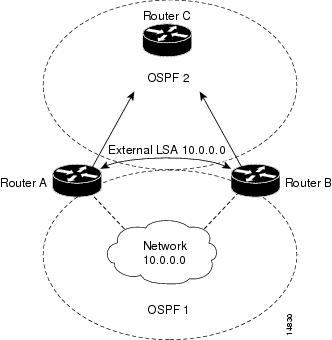
Router A Configuration
router ospf 1
 redistribute ospf 2 subnet
 distance ospf external 200
!
router ospf 2
 redistribute ospf 1 subnet
 distance ospf external 200
Router B Configuration
router ospf 1
 redistribute ospf 2 subnet
 distance ospf external 200
!
router ospf 2
 redistribute ospf 1 subnet
 distance ospf external 200
Example: OSPF over On-Demand Routing
The following configuration allows OSPF over an on-demand circuit, as shown in the figure below. Note that the on-demand
circuit is defined on one side only (BRI 0 on Router A); it is not required to be configured on both sides.
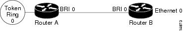
Router A Configuration
username RouterB password 7 060C1A2F47
isdn switch-type basic-5ess
ip routing
!
interface TokenRing0
 ip address 192.168.50.5 255.255.255.0
 no shutdown
!
interface BRI0
 no cdp enable
 description connected PBX 1485
 ip address 192.168.45.30 255.255.255.0
 encapsulation ppp
 ip ospf demand-circuit
 dialer map ip 192.0.2.6 name RouterB broadcast 61484
 dialer-group 1
 ppp authentication chap
 no shutdown
!
router ospf 100
 network 192.168.45.0 0.0.0.255 area 0
 network 192.168.45.50 0.0.0.255 area 0
!
dialer-list 1 protocol ip permit
Router B Configuration
username RouterA password 7 04511E0804
isdn switch-type basic-5ess
ip routing
!
interface Ethernet0
 ip address 192.168.50.16 255.255.255.0
 no shutdown
!
interface BRI0
 no cdp enable
 description connected PBX 1484
 ip address  192.168.45.17 255.255.255.0
 encapsulation ppp
 dialer map ip 192.168.45.19 name RouterA broadcast 61485
 dialer-group 1
 ppp authentication chap
 no shutdown
!
router ospf 100
 network 192.168.45.0 0.0.0.255 area 0
 network 192.168.45.50 0.0.0.255 area 0
!
dialer-list 1 protocol ip permit
Example: LSA Group Pacing
The following example changes the OSPF pacing between LSA groups to 60 seconds:
router ospf
 timers pacing lsa-group 60
Example: Blocking OSPF LSA Flooding
The following example prevents flooding of OSPF LSAs to broadcast, nonbroadcast, or point-to-point networks reachable through
Ethernet interface 0:
interface ethernet 0
 ip ospf database-filter all out
The following example prevents flooding of OSPF LSAs to point-to-multipoint networks to the neighbor at IP address 10.10.10.45:
router ospf 109
 neighbor 10.10.10.45 database-filter all out
Example: Ignoring MOSPF LSA Packets
The following example configures the router to suppress the sending of syslog messages when it receives MOSPF packets:
router ospf 109
 ignore lsa mospf
Additional References for
OSPF Not-So-Stubby Areas (NSSA)
Related Documents
|
Related |
Document |
|---|---|
|
Cisco IOS |
|
|
OSPF |
|
|
Protocol-independent features that work with OSPF |
“Configuring IP Routing Protocol-Independent Features” module in |
RFCs
|
RFC |
Title |
|---|---|
|
RFC 1587 |
|
|
RFC 3101 |
|
Technical Assistance
|
Description |
Link |
|---|---|
|
The Cisco |
http://www.cisco.com/cisco/web/support/index.html |
Feature Information for
Configuring OSPF
The following table provides release information about the feature or features described in this module. This table lists
only the software release that introduced support for a given feature in a given software release train. Unless noted otherwise,
subsequent releases of that software release train also support that feature.
Use Cisco Feature Navigator to find information about platform support and Cisco software image support. To access Cisco
Feature Navigator, go to www.cisco.com/go/cfn. An account on Cisco.com is not required.
В этой статье мы будем использовать MIkroTik с RouterOS версии 7.2 для изучения протокола динамической маршрутизации OSPF.
Введение
Протокол OSPF (Open Shortest Path First) — это протокол динамической маршрутизации, который ищет кратчайший путь (маршрут) используя алгоритм Дейкстры. Перед тем, как начать обмен маршрутной информацией между роутерами, им необходимо установить соседские отношения. Для этого между роутерами должна быть IP связность.
OSPF — это масштабируемый протокол и если нужно объединить много роутеров в одну автономную систему эти роутеры можно поделить на зоны (Area). Но в статье это не рассматривается.
Для обмена маршрутной информацией используются специально выделенные мультикастовые адреса:
- 224.0.0.5
- 224.0.0.6
То-есть для работы OSPF мультикаст должен быть разрешен.
Схема сети (broadcast)
У нас есть 4 роутера и все они находятся в одном широковещательном домене (broadcast), например подключены к одному коммутатору. Эти роутеры обслуживают некоторые локальные сети. И мы с помощью OSPF создадим таблицы маршрутизации на каждом роутере MikroTik, так чтобы из каждой подсети можно было попасть в каждую подсеть.
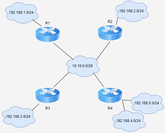
Вся настройка OSPF в MikroTik у нас находится в меню /Routing/OSPF.
Создание инстанса OSPF
Вначале на вкладке Instances создаём на каждом роутере свой инстанс:
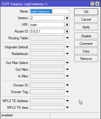
Можно ничего не менять, а можно указать RouterID. Он указывается в виде похожем на ip адрес, но это не ip адрес, это идентификатор роутера. И соседские роутеры знают друг друга по этим идентификаторам. Если появятся два роутера с одинаковыми идентификаторами, то роутеры запутаются. В OSPF каждый роутер должен иметь уникальный номер. Я на первом роутере указываю 0.0.0.1, на втором 0.0.0.2 и так далее.
Если бы мы не указали на каждом роутере свой Router ID, то роутеры бы автоматически назначили его себе, взяв какой-нибудь из своих ip адресов. Но лучше задать Router ID вручную, а не доверять глупой железке.
Создание зоны OSPF
Дальше переходим на вкладку Areas и создаём новую зону OSPF. Здесь ничего не меняем, на каждом роутере всё оставляем по умолчанию:
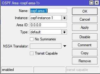
В этой статье я не рассказываю про деление автономной системы на зоны и объединение зон. И так как зона у нас одна, то создаём её по умолчанию.
Указываем интерфейсы которые будут участвовать в обмене OSPF
Переходим на вкладку Interface Templates и создаём шаблоны. В шаблоне обязательно нужно указать интерфейс. Дополнительно можно указать определённую подсеть, маршрут к которой будет передаваться по OSPF на остальные роутеры. Также нужно указать тип сети, если роутеры находятся в одном широковещательном домене (как у нас), то указывается broadcast. А если они соединены по типу точка-точка (патч-кордами или L3_VPN-ами), то тип сети будет ptp (peer-to-peer).
Также, если интерфейс обслуживает локальную сеть, где находятся только конечные устройства пользователей, то нужно поставить галочку Passive, чтобы в эту локалку не отправлялись OSPF пакеты. А шаблон делаем, для того чтобы опубликовать эту сеть в OSPF.
А если вам к определённым сетям, за определёнными интерфейсами не нужно передавать маршруты. И эти интерфейсы не должны участвовать в OSPF, то просто не создавайте для этих интерфейсов шаблоны.
Вот пример моих настроек на первом роутере:
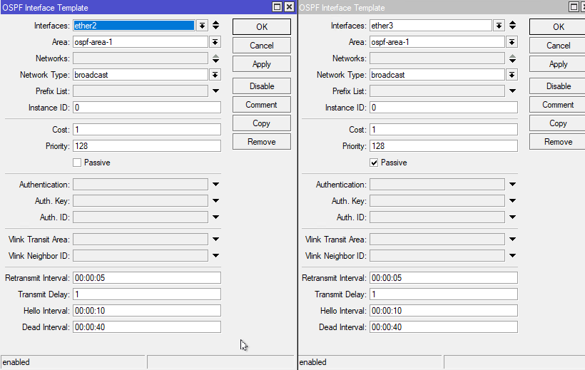
Интерфейс ether2 у меня идет в широковещательный домен, по которому будет происходить обмен OSPF пакетами. Поэтому я указываю тип сети Broadcast и не ставлю галочку Passive.
Интерфейс ether3 у меня обслуживает локальную сеть, маршрут к которой я хочу опубликовать. Но я не хочу пускать туда OSPF трафик. Поэтому я ставлю галочку Passive. Тип сети Broadcast, так как интерфейс обслуживает локальную сеть, а не одно устройство.
Все остальные настройки оставляю по умолчанию. И создаю по 2 таких шаблона на каждом роутере.
Просмотр соседей OSPF
Чтобы убедиться что всё работает перейдите на вкладку Neighboards:
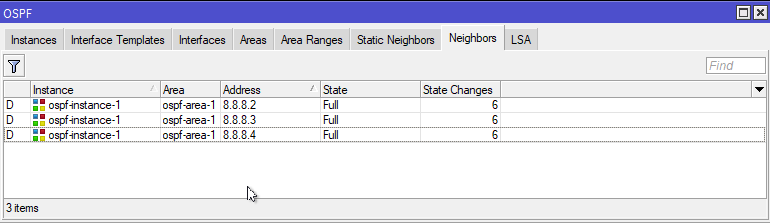
Соседство определяется состоянием (State). Если оно полное (Full), значит все в порядке и роутеры начали обмениваться маршрутами. Ещё одним рабочим состоянием является TwoWay (двухстороннее соединение), но только для Broadcast соединения.
Дело в том, что в Broadcast соединении происходит выбор главного маршрутизатора — DR и резервного главного маршрутизатора BDR. А все остальные роутеры называют DROTHER. Вот между DROTHER будет состояние не Full а TwoWay и они не будут между собой обмениваться маршрутной информацией.
А если у вас тип сети PTP, то все роутеры будут иметь соседство Full.
Немного теории (основные понятия и состояния соседства)
В самом начале роутеры с включенным и настроенном OSPF начинают искать соседей. Затем с найденными соседями устанавливаются соседские отношения. При этом роутеры договариваются о том как будет происходить обмен информацией о маршрутах.
И так у нас сейчас OSPF работает в broadcast (ethernet) среде. И алгоритм при этом немного отличается от работы в среде peer-to-peer. Главным отличаем работы в broadcast — является процесс выборов DR и BDR.
Основные понятия:
- LSDB — база данных маршрутной информации.
- Hello пакет — используется для обнаружения соседей, построения соседских отношений и мониторинга доступности соседа.
- DBD пакет — проверяет синхронизацию базы данных (LSDB) между роутерами. С помощью DBD роутер сообщает, какие у него есть соседи.
- LSR — запрос определенных записей из LSDP соседа. То есть роутер получает DBD от соседа и понимает что у его соседа есть ему неизвестные соседи. И чтобы понять как до них добраться и какие у них есть опубликованные сети, роутер запрашивает эту информацию с помощью LSR запроса.
- LSU — отправка определенных записей из LSDB в ответ на запрос (LSR).
Состояния соседства:
- Down — самое первое состояние, когда роутер ещё не начал посылать Hello пакеты для поиска соседей.
- Init — как только роутер отправляет свой первый Hello пакет соседу, то он переходит в состояние Init и начинает ждать Hello пакеты от соседей.
- TwoWay — в этом состоянии соседи могут остаться, но только в broadcast среде и если их больше трёх. При установке соседских отношений роутеры отправляют сообщение hello друг другу два раза. Первый раз чтобы нащупать соседа, а второй раз, чтобы сообщить соседу о том, что его заметили и с ним хотят дружить. Во втором hello пакете роутер посылает Router ID соседа. И если роутер видит в этом пакете свой Router ID, то он переходит в TwoWay. Другими словами, в этом состоянии роутер знает, что сосед про него знает. Также в этом состоянии проходят выборы за роль DR и BDR (об этом ниже).
- Exstart – здесь роутеры договариваются о том, кто первый начнет обмен. Для этого из двух соседей выбирается главный роутер (master), и второстепенный (slave). Главным становится тот роутер, у которого Router ID больше.
- Exchange – роутеры начинают обмениваться DBD пакетами. При этом master посылает DBD первым, то есть сообщает, какие у него есть соседи.
- Loading – переход в это состояние происходит тогда, когда роутер осознает, что в его LSDB не хватает части маршрутной информации. То есть соседа он уже знает, нужно узнать какие сети обслуживает сосед и какие у него есть соседи, и какие сети есть у соседей. В этом состояние роутер отсылает LSR запросы. И в ответ он получает LSU ответы, и наполняет свою базу LSDB.
- Full – после того, как база данных LSDB у соседей синхронизовалась, роутеры переходят в это состояние.
Немного теории (что такое DR и BDR и зачем нужно голосование)
Когда у вас широковещательная среда (broadcast). То каждый OSPF роутер должен синхронизировать свою базу LSDB с базами других роутеров. В такой среде может быть очень много OSPF роутеров. Ни как у нас 4, а например 100. И представьте что 100 роутеров начнут синхронизацию каждый с каждым. Это очень серьёзно нагрузить broadcast среду.
Разработчики OSPF решили что в broadcast среде обмен маршрутной информацией будет происходить не каждый с каждым, а каждый с главным. И этот главный будет передавать свою большую LSDB всем остальным. Такой главный роутер назвали DR (designated router).
Но если что-то случится с DR, то все соседские отношения рухнут. Чтобы этого не произошло в процессе выборов выбирают ещё BDR (backup designated router). BDR точно также как и DR наполняет свою базу LSDB, но не распространяет её. Но если что-то случится с DR, то он его заменит его.
А роутеры которые не стали DR и BDR называют DROTHER. Роутеры DROTHER имеют статус соседства FULL с роутерами DR и BDR (то есть кидают LSR и получают LSU). А соседство двух роутеров DROTHER описывается состоянием TwoWay (синхронизации не происходит). Вот поэтому в broadcast среде, где больше трёх роутеров, можно наблюдать соседство TwoWay и при этом всё корректно работает.
Посмотрим таблицу маршрутизации
После прочтения теории, если вы её осилили, вернёмся к нашей сети и посмотрим какие маршруты мы получили по протоколу OSPF:
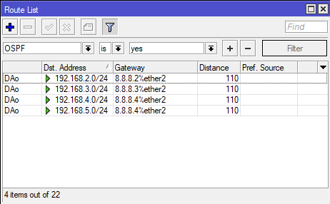
То есть теперь мы можем получить доступ ко всем подсетям.
Схема сети (точка — точка)
Теперь немного изменим условия. Допустим эти 4 роутера не в одном широковещательном домене а соединены по типу точка-точка (ptp). Например патч-кордами, или L3_VPN. При этом, у меня, каждый роутер соединён с каждым другим роутером:
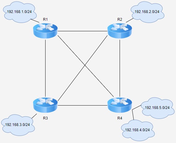
Изменяем Interface Templates
Заходим на каждый роутер, и отключаем шаблон, который был для broadcast (в моём случае это ether2). И затем создаём новые шаблоны для соединений по типу peer-to-peer (в моём случае это vpn). Получается вот так:
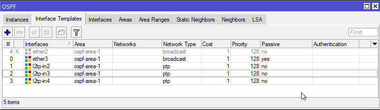
Это проделывается на всех роутерах.
Просмотр соседей OSPF
Затем перейдём на вкладку Neighbors, чтобы посмотреть соседей OSPF и их состояния:
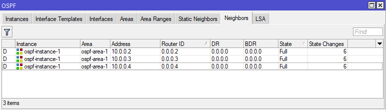
В этом случае (ptp), чтобы все работало, состояния должно быть Full и никакими другими. Так как здесь не идет голосования и нет DR и BDR роутеров.
Посмотрим таблицу маршрутизации
После того, как мы убедились в полном соседстве наших роутеров, посмотрим на таблицу маршрутизации на первом роутере:
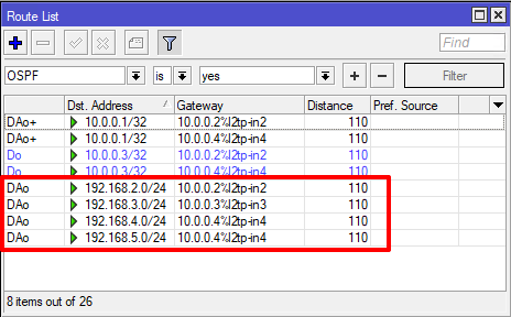
Теперь у нас есть доступ ко всем подсетям, через vpn соединения.
Перестройка маршрутов
И так из первой подсети (192.168.1.0/24) в четвертую (192.168.4.0/24) и пятую подсеть (192.168.5.0/24) пакеты пойдут через l2tp-in4.
Как только упадет VPN между 1 и 4 роутером, маршруты перестроятся:
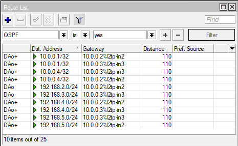
Теперь в 4 и 5 подсеть с первого роутера пакеты пойдут через l2tp-in2 и l2tp-in3 используя ECMP. То есть половина соединений пойдет через R2, а половина через R3. И периодически такие соединения будут перестраиваться, что не совсем правильно.
Когда мы создавали Interface Templates мы не меняли параметр Cost. Поэтому у нас цена каждого соединения равна единицы. Вот как это выглядит, если потеряно соединение R1 с R4:
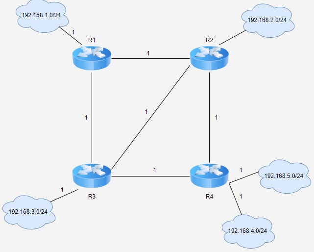
То есть кратчайшем путём от первой подсети к пятой подсети будет через R1 — R2 — R4 или через R1- R3 — R4. И эти пути равны. А так как у нас два равноценных пути, то в работу вступает ECMP.
Чтобы это исправить, нужно на роутере R1 в Interface Templates увеличить стоимость (Cost) перехода к R3:
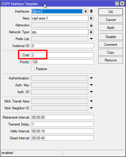
Теперь наша схема изменится:
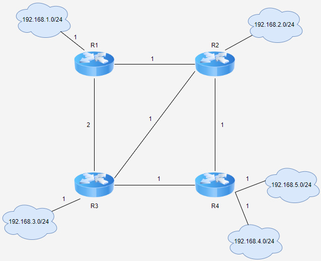
Теперь кратчайшем путём от первой подсети к пятой подсети будет через R1 — R2 — R4, а путь R1- R3 — R4 будет дороже.
Чтобы в этом убедиться посмотрим таблицу маршрутизации:
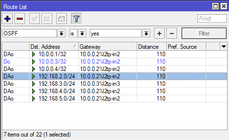
Видим что действительно пакеты в 4 и 5 подсети пойдут через R2 (l2tp-in2).
Итог
Мы узнали как настроить на роутерах MikroTik обмен маршрутной информацией с помощью протокола OSPF.
Узнали что для этого нужно:
- Создать инстанс (Instances)
- В нем указать RouterID для каждого роутера
- Создать зону (Area)
- Создать шаблон для интерфейса (Interface Templates)
- Указать интерфейс
- Если нужно, указать подсети
- Указать тип соединения
- Если нужно, поменять параметр Cost
- Если нужно, поставить галочку Passive
- Проследить за соседями (Neighbors) и посмотреть какие маршруты прилетели к нам по OSPF (IP / Routes)
Также вы узнали что OSPF работает по мультикасту и нужна IP связность. А также в различных средах (broadcast / ptp) алгоритм установки соседских отношений может отличаться.
Вы узнали что в broadcast среде роутеры выбирают себе DR и BDR, и обмениваются маршрутной информацией только через DR, а не каждый с каждым.
Сводка

Имя статьи
MIkrotik. OSPF на примере 4 роутеров
Описание
В этой статье мы будем использовать MIkroTik с RouterOS версии 7.2 для изучения протокола динамической маршрутизации OSPF
В данной статье можно ознакомиться с базовой настройкой протокола динамической маршрутизации OSPF, на примере подключения двух роутеров.
Знакомство с протоколом OSPF
OSPF (англ. Open Shortest Path First) — протокол динамической маршрутизации, основанный на технологии отслеживания состояния канала.
Протокол OSPF распространяет информацию о доступных маршрутах между маршрутизаторами одной автономной системы.
OSPF имеет следующие преимущества:
- Высокая скорость сходимости по сравнению с дистанционно-векторными протоколами маршрутизации;
- Поддержка сетевых масок переменной длины (VLSM);
- Оптимальное использование пропускной способности с построением дерева кратчайших путей.
Использование протокола OSPF при настройке роутеров
OSPF протокол является стандартом для сетевых инженеров, которые работают с большим количеством сетевого оборудования. По сути, с помощью этого протокола можно передавать маршрутную информацию разным устройствам. В качестве примера рассмотрим базовую настройку между двумя роутерами.
Ping
Имеются два роутера, у которых есть прямое подключение. Таким образом при написании команды ping для обоих роутеров можно проверить доступны ли они.
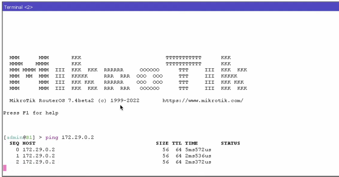
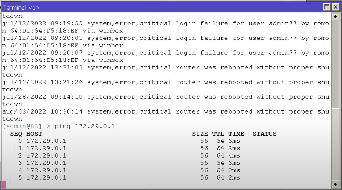
На рисунке 3 видно, что устройство B1 у нас доступно через ether2 и ether4.
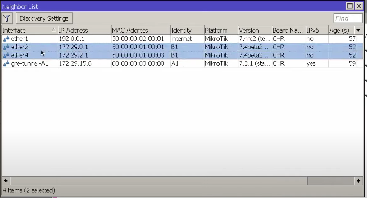
Настройка первого роутера
Настроим роутер B1, на котором установлена операционная система RouterOS 7.4 и здесь создаем Instances, где можно оставить настройки по умолчанию:
- Вторая версия протокола говорит о том, что мы работаем с ipv4 протоколом.
- В VRF стоит main то есть оставляем все в основной таблице маршрутизации
- Router ID оставляем по умолчанию
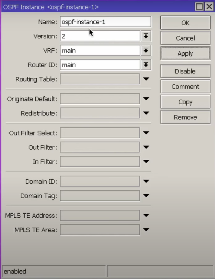
В разделе Interface Templates можно увидеть, что у нас не создана Area, как представлено на рисунке 5.
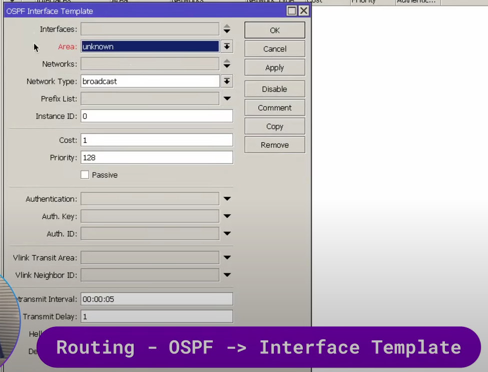
В RouterOS 6 создана backbone Area, без которой невозможно работа у протокола OSPF, поэтому называние будет таким же. И Area ID это 32-битное число 0:0:0:0 как показано на рисунке 6.
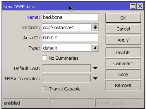
Дальше создаем шаблон интерфейса и указываем соседний интерфейс.
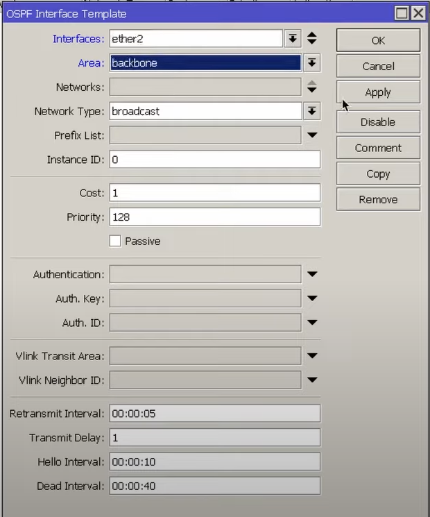
Настройка второго роутера
Переходим к настройке второго роутера. Здесь у нас настройки будут отличаться, потому что у нас RouterOS 6.
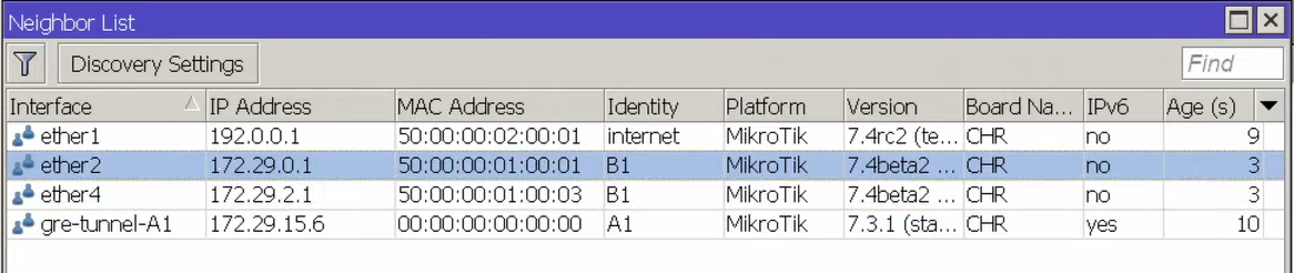
Instances и Areas нам создавать не требуется, так как они у нас уже есть. Далее указываем сеть, которая настроена между двумя нашими роутерами.
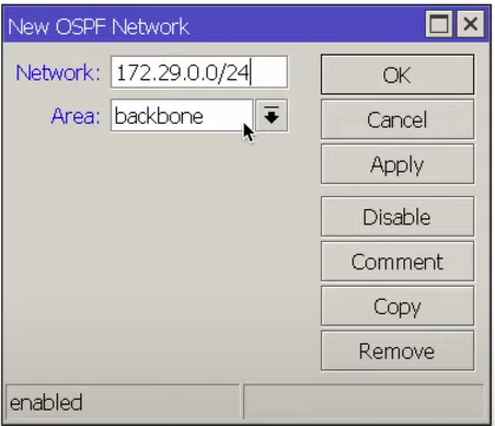
В разделе Interface для ether2 смотрим Status o подключении Neighbors на рисунке 9
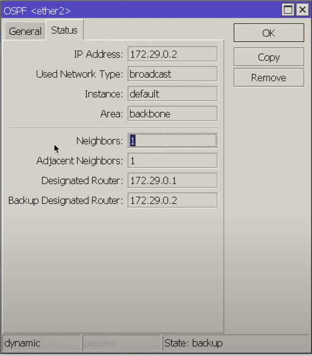
В разделе Neighbors можем посмотреть соседнее устройство, а также его состояние.
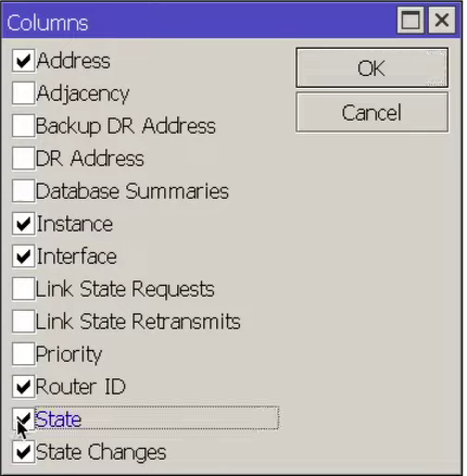
В данном случае Full, то есть, между соседними устройствами налажена полноценная работа.
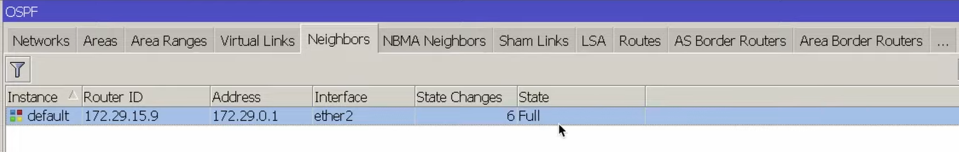
Дополнительная сеть для передача маршрутной информации
На RouterOS6
Чтобы передать соседу какую-то маршрутную информацию для этого перейдём в раздел OSPF Network Address и пропишем какую-нибудь дополнительную сеть, которая есть на нашем роутере.
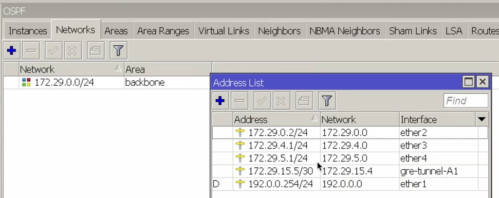
В качестве примера возьмем пятую сеть.
Network:172.29.5.0/24
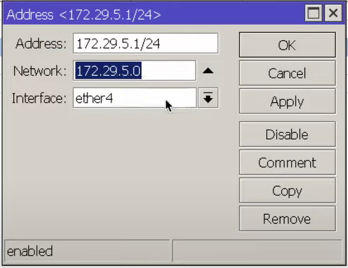
Указываем IP адрес и ID новой сети.
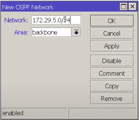
После чего, смотрим появилась ли данная сеть в разделе IP Routers и выставляем фильтр OSPF и yes.
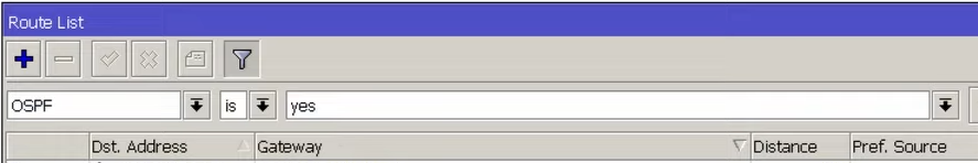
Видим, что данная сеть принадлежит соседнему устройству. Также она есть на нашем роутере, но мы можем выключить адрес и эта сеть будет активной.
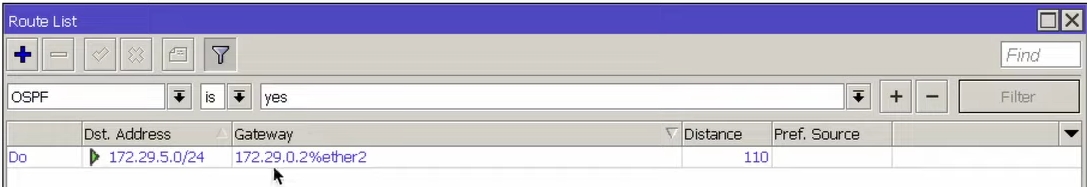
RouterOS 7
Возможно и с RouterOS 7 прописать какую-либо сеть, которую нужно будет передать соседнему устройству.
В качестве примера возьмем вторую сеть.
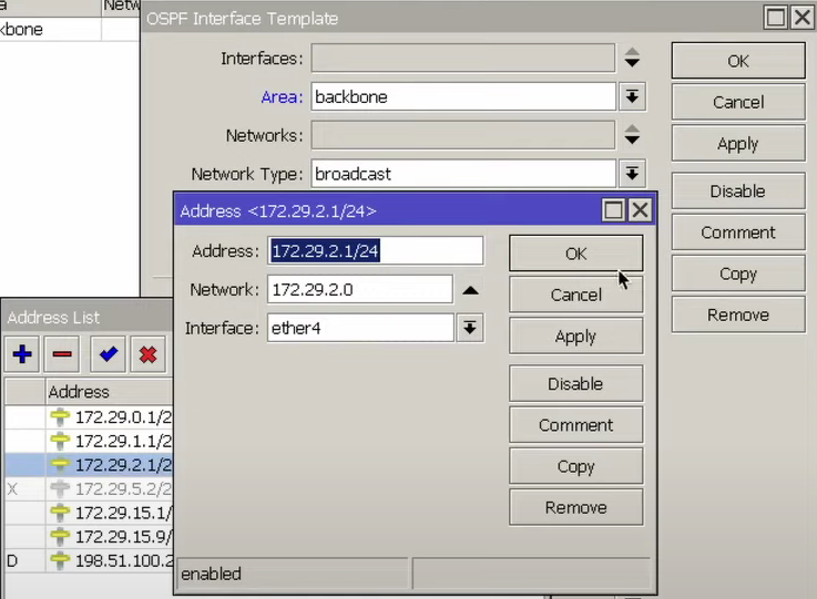
Указываем интерфейс, за которым есть соседнее устройство.
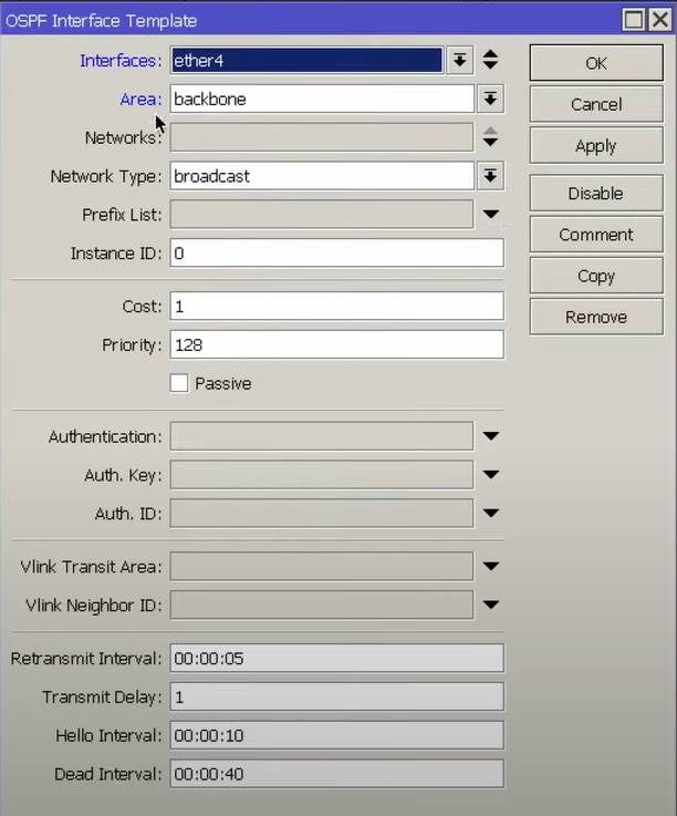
В разделе Routes можно увидеть, что появилась вторая сеть.
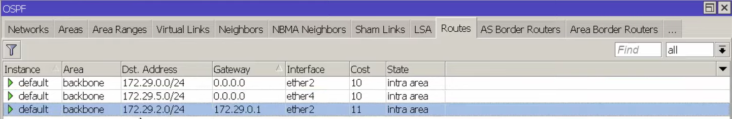
Обмен маршрутной информацией и трафиком по двум интерфейсам
Дополнительно для нашего случая, когда роутеры соединены более чем одной сетью, то есть у нас есть основной и резервный интерфейс можно
настроить обмен маршрутной информации, так чтобы весь трафик шел по
двум интерфейсам одновременно.
В раздел IP Neighbors видим информацию о ether2 и ether4.
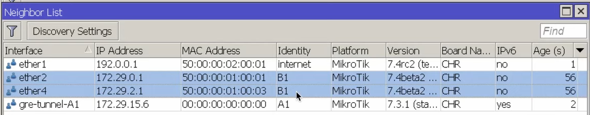
Переходим на первый роутер, который у нас на RouterOS 7 и указываем ему ether4 пятую сеть, по которой он увидит своё соседнее устройство.
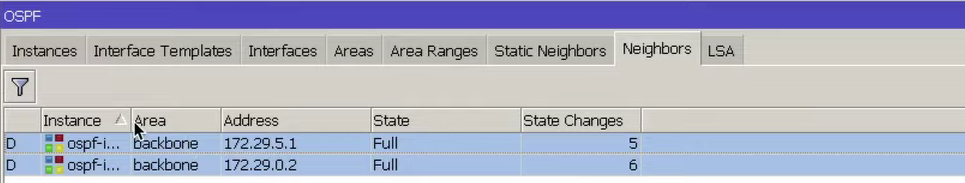
Далее открывает раздел IP Routers, но маршруты никакие не передаем.
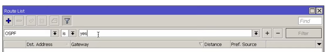
Можно четвертую сеть прописать так, чтобы она шла в RIP для этого, перейдем в раздел OSPF Network и добавляем 172.29.4.0/24, также в нашу Area.
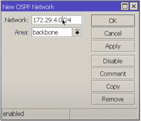
В разделе Neighbors видим, что нам пришло два маршрута причем с пометкой ECMP, то есть работа осуществляется одновременно по двум интерфейсам.
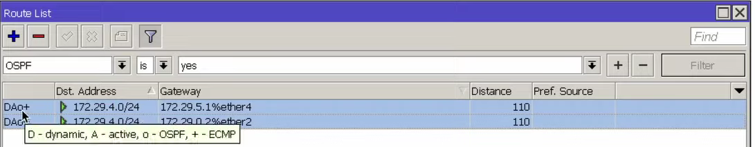
Пассивный интерфейс
Есть возможность сделать интерфейс пассивным, то есть на нем не будет передаваться никаких OSPF сообщений по 89 протоколу.
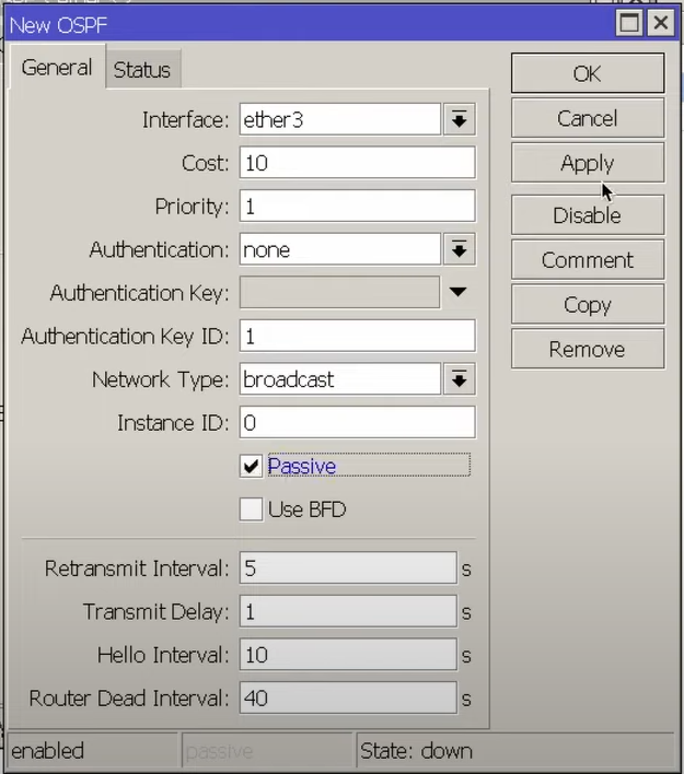
На RouterOS 7 также можно настроить пассивность интерфейса.
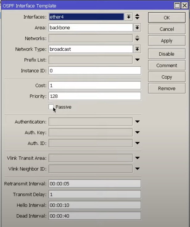
Влияние цены на выбор интерфейса и на активность маршрутов
На RouterOS 7
Выбор интерфейса основывается на цене. Чем выше стоимость, тем меньше вероятность что именно этот интерфейс будет выбран для передачи трафика. То есть, сделать так, чтобы по ether2 информация в сторону соседа не проходила, можно увеличив стоимость. Таким образом для ether2 стоимость будет 100, а для ether4 стоимость будет 1.
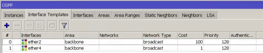
Тогда в таблице маршрутизации второй маршрут будет подсвечен синим, то есть он в данном случае не активен, но он может стать иным в ситуации если выключится ether4.
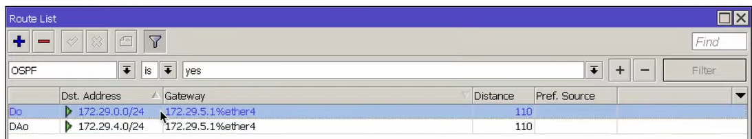
Например, если выключить интерфейс ether4, то трафик пойдет по интерфейсу ether2 и только в этой ситуации он станет активным.
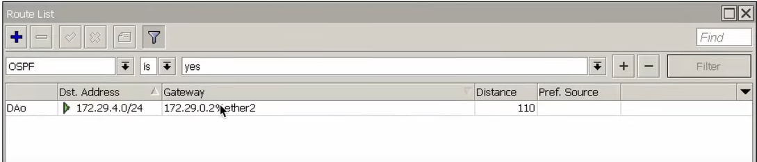
При возвращении ether4 обратно ему нужно какое-то время на то, чтобы договориться с соседним устройством и без проблем вернуться в таблицу маршрутизации.
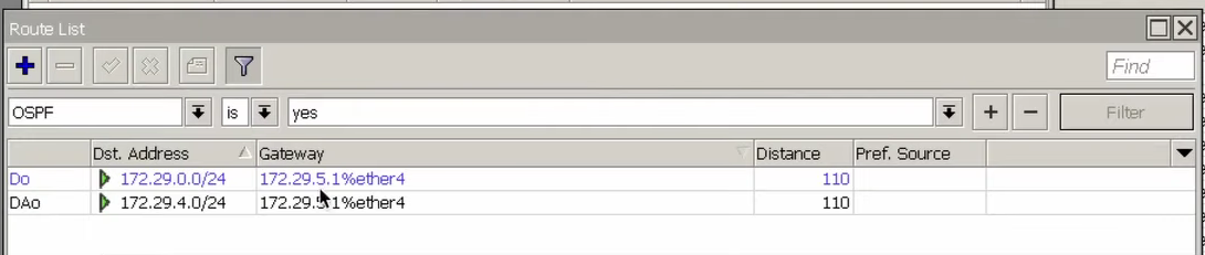
На RouterOS 6
На RouterOS 6 также можем выбрать интерфейс. Необходимо зайти в раздел Routing OSPF Interface скопировать необходимый нам интерфейс и, указать стоимость, там где мы не пойдем.
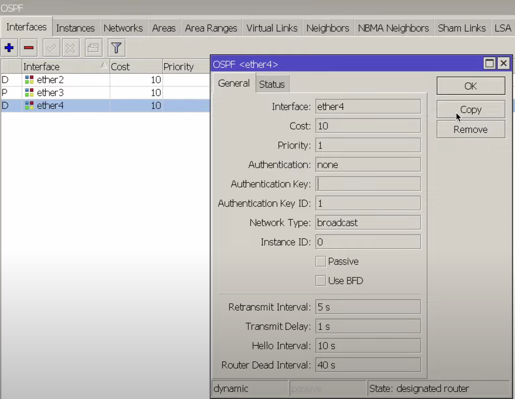
И в разделе IP Routes до соседнего устройства будет осуществляться соединение через ether2. Если бы стоимость была одинаковая, то был бы ESMP маршрут.
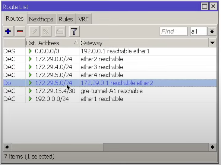
На рисунке 32 видно, что у нас появился ESMP маршрут, то есть который указывает что у нас есть выбор Gateway через ether4 и через ether2.
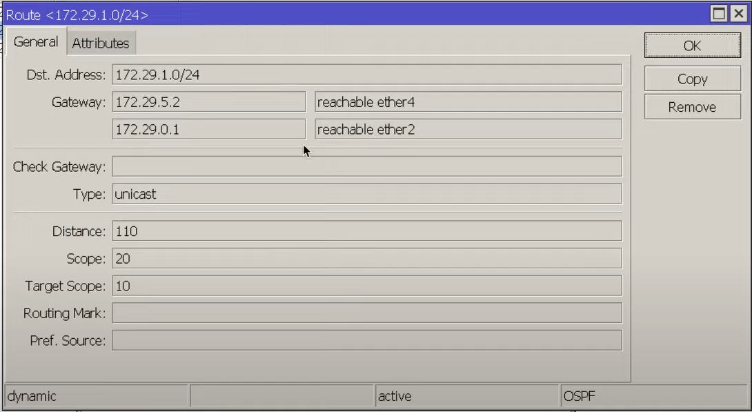
Если опять изменим стоимость на одинаковую, то настройки вернутся к исходным.
На этом базовый обзор протокола OSPF и настройка роутеров закончена.