In this network, a router and 2 PCs are used. Computers are connected with routers using a copper straight-through cable. After forming the network, to check network connectivity a simple PDU is transferred from PC0 to PC1. The network simulation status is successful. From this network, it can be observed that the router handles data transfers between multiple devices.
Procedure:
Step-1(Configuring Router1):
- Select the router and Open CLI.
- Press ENTER to start configuring Router1.
- Type enable to activate the privileged mode.
- Type config t(configure terminal) to access the configuration menu.
- Configure interfaces of Router1:
• Type interface FastEthernet0/0 to access FastEthernet0/0 and Configure the FastEthernet0/0 interface with the IP address 192.168.10.1 and Subnet mask 255.255.255.0.
• Type interface FastEthernet0/1 to access GigabitEthernet0/0 and Configure the FastEthernet0/1 interface with IP address 192.168.20.1 and Subnet mask 255.255.255.0.
6. Type no shutdown to finish.
Router1 Command Line Interface:
Router>enable
Router#config t
Enter configuration commands, one per line. End with CNTL/Z.
Router(config)#interface FastEthernet0/0
Router(config-if)#ip address 192.168.10.1 255.255.255.0
Router(config-if)#no shutdown
Router(config-if)#
%LINK-5-CHANGED: Interface GigabitEthernet0/0, changed state to up
Router(config-if)#interface FastEthernet0/1
Router(config-if)#ip address 192.168.20.1 255.255.255.0
Router(config-if)#no shutdown
Step-2(Configuring PCs):
- Assign IP Addresses to every PC in the network.
- Select the PC, Go to the desktop and select IP Configuration and assign an IP address, Default gateway, Subnet Mask
- Assign the default gateway of PC0 as 192.168.10.1.
- Assign the default gateway of PC1 as 192.168.20.1.
Step-3(Connecting PCs with Router):
- Connect FastEthernet0 port of PC0 with FastEthernet0/0 port of Router1 using a copper straight-through cable.
- Connect FastEthernet0 port of PC1 with FastEthernet0/1 port of Router1 using a copper straight-through cable.
Router Configuration Table:
| Device Name | IP address FastEthernet0/0 | Subnet Mask | IP Address FastEthernet0/1 | Subnet Mask |
| Router1 | 192.168.10.1 | 255.255.255.0 | 192.168.20.1 | 255.255.255.0 |
PC Configuration Table:
| Device Name | IP address | Subnet Mask | Gateway |
| PC 0 | 192.168.10.2 | 255.255.255.0 | 192.168.10.1 |
| PC 1 | 192.168.20.2 | 255.255.255.0 | 192.168.20.1 |
Designed Network topology:

Simulation of Designed Network Topology:
Sending a PDU From PC0 to PC1:


Acknowledgment From PC1 to PC0:


Last Updated :
10 Nov, 2021
Like Article
Save Article
Packet Tracer Cisco CLI Commands list
Here is the detailed Cisco router configuration commands list, which can be implemented with packet tracer. Packet tracer is a network simulator used for configuring and creating the virtual cisco devices and network. There are also some other similar software but Cisco IOS output will be same on all simulators.
Related Article: PowerShell vs Command prompt
Cisco Router Configuration Step By Step
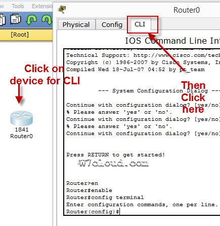
To configure any device in packet tracer you are required to open or access its CLI. You can do it by clicking any device and then navigating to CLI tab. Once you are at CLI you can perform all Cisco Commands here.

Cisco IOS supports numerous command modes which can be practice with packet tracer, followings are the main command modes of cisco CLI with specific commands to navigate from one mode to another. Also Check out some best cheap routers for real practice.
| Mode | Symbol | How to access this mode | Command for leaving this mode |
| User EXEC Mode | Router > | Default mode after booting. Press enter for accessing this. | Use exit command |
| Privileged EXEC mode | Router # | Use enable command from user exec mode for entering into this mode | exit |
| Global Configuration mode | Router(config)# | Use configure terminal command from privileged exec mode | Exit or Ctrl+Z for user EXEC mode |
| Interface Configuration | Router(config-if)# | Use interface <interface name+number> command from global configuration mode | Use exit command to return in global mode |
| ROMMON | ROMMON > | Enter reload command from privileged exec mode. Press CTRL + C key combination during the first 60 seconds of booting process. | Use exit command.
Watch a video of rommon mode |
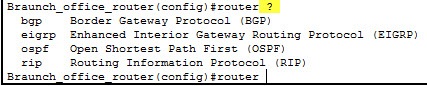
IOS commands are not case sensitive it means that you can use them in uppercase, lowercase, or mixed case, but passwords are case sensitive. Therefore make sure you type it in correctly. In any mode, you can obtain a list of commands available on that mode by entering a question mark (?).
How to Change the Cisco Router name
You can change the cisco router name by using command hostname in global configuration mode.
![]()
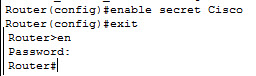
How to set the Enable password:
You can set the password for protecting enable mode by following command: (Following command will set the password to cisco)
How to set the telnet password on Cisco:
You can access the cisco router remotely by VTY lines, these are the Virtual Terminal lines for access router, you can set password on these line by using the following commands:
Router(config)#line vty 0 4
Router(config-line)#password Cisco
Router(config-line)#no login
The above command will set the telnet password to “Cisco”.
How to set the IP address to Cisco interface:
You can set the IP address to any Cisco device interface by using the following commands:
Router(config)#interface <interface name&number>
Router(config-if)#ip address <IP address> <subnet mask>
How to enable a port or interface
Router(config-if)#no shut
Example:
![]()
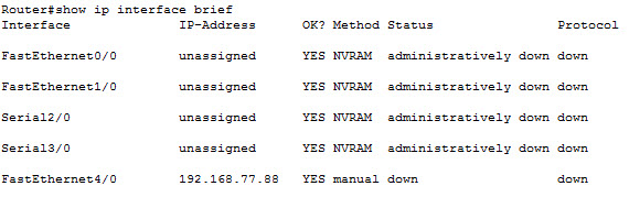
How to check the IP address of all interfaces:
You can use the “show ip interface brief” command in Privileged EXEC mode for checking the IP address of all interface of Cisco device.
How to save the configurations:
You can use the following command for router configuration to Nvram for use at next boot up
Router#copy running-config startup-config
How to configure the access-list on Cisco:
You can configure the access-list on cisco by using following commands:
Router(config)#Access-list <number> <permit|deny> <ip> <mask>
Router(config-if)#ip access-group <number> <in|out>
OR
Router(config)#Access-list <number> <permit|deny> <protocol> <from ip and mask> <to ip and mask> <port number>
Router(config-if)#
Command Example:
Router(config)#access-list 2 deny 192.168.0.33 0.0.0.255
Router(config)#interface fastEthernet 4/0
Router(config-if)#ip access-group 2 in
How to configure the default route on Cisco:
Following command will set the default route to 10.10.10.101.
Router(config)# ip route 0.0.0.0 0.0.0.0 10.10.10.101
How to create a static route on Cisco router
Router(config-router)#ip route [destination_network] [mask] [next-hop_address
you can set a static route by using above command example is also given below:
Router(config-router)#ip route 192.132.23.1 255.255.255.0 10.10.10.1
—————————
——————-
| RIP Configuration Commands | |
| Commands | Details |
| Router(config)#Router rip | Enable RIP routing on router. |
| Router(config-router)#Network <network ip address>
Why we use RIP? |
Define the network which you want to advertise in RIP. E.g. Network 192.168.88.0 |
|
OSPF Configuration Commands |
|
| Router(config)#Router ospf <process-id> | Enable OSPF routing on router. Process-id is any number & must be same for all networks in AS. |
| Router(config-router)#Network < ip address> <wild cardmask>
Why we use OSPF? |
IP address is the IP of network which will be advertise in OSPF and wild card mask will represent the network bits. E.g. network 192.168.1.0 0.0.255.255 is equilent to 192.168.0.0/16 |
| EIGRP configuration Commands | |
| Router(config)#Router eigrp <AS number> | AS number is a number must be same for networks which are desired to connect with each other. E.g. Router eigrp 1 |
| Router(config-router)#Network < ip address> | Advertise network in EIGRP |
| Router(config-router)#no auto-summary
Why we use EIGRP? |
Disable auto summay |
banner motd <banner start identification> banner message <banner end identification>
Command Example:
banner motd #Unauthorized access to this device is prohibited!#
Above command with set the banner to “Unauthorized access to this device is prohibited”
Famous Show Commands in Privileged EXEC Mode
You can run all these command for checking different setting of Cisco device in privileged EXEC mode:
Show Version
Show running-config
Show Vlan
Show mac-address-table
Show clock
Show privilege
Show interface <interface name>
show ip route
Show controllers
show cdp neighbors
Show memory
Show protocols
Show startup-config
Show Flash
Show spanning-tree
Verifying Commands for Network Connectivity
You can use these commands to verify network connectivity for your router
router# enable
router# ping [ip-address | hostname]
Command Example:
router# ping 192.168.3.1
(A reply response from host 192.168.3.1 will verify the connectivity)
How to telnet any host:
telnet {ip-address | hostname}
e.g. router# telnet 192.168.3.1
Related Article: NMAP Commands Linux

Me Waqas Azam and I am a professional blogger & freelance writer. I also working in the IT industry for over 7 years. I am graduated in Computer Science and information technology.
Cisco Packet Tracer является отличным инструментом моделирования и визуализации сети, полезным как для обучения как студентов, так и продвинутых пользователей, у которых под рукой нет физического оборудования компании Cisco. Программа-симулятор позволяет настраивать (виртуально) различное телекоммуникационное оборудование фирмы Cisco (коммутаторы, маршрутизаторы, ip-телефоны, шлюзы, сервера, межсетевые экрана Cisco ASA и многое другое). Интерфейс прост и понятен, и вы сможете создать и сконфигурировать простые сети в Packet Tracer даже если обладаете глубокими познаниями в сетевых технологиях или оборудовании Cisco. Многие используют данное ПО для проектирования и моделирования сетей, обучения студентов, подготовке к сертификационным экзаменам CCNA/CCNP, получения практических навыков поиска и устранения проблем в сетях на оборудовании Cisco.
Несмотря на то, что Cisco Packet Tracer недоступен для бесплатного скачивания (доступен только участникам программы сетевой академии Cisco Networking Academy), вы с легкостью найдете дистрибутив на просторах сети. На текущий момент актуальной является версия Cisco Packet Tracer 7.2.1. При использовании Cisco Packet Tracer вам нужно указать, что вы хотите использовать гостевой доступ. Кроме того, есть бесплатные версии Cisco Packet Tracer для Android и iOS.
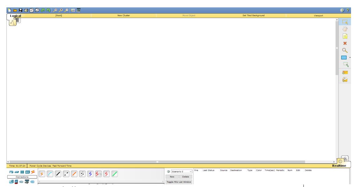
Чтобы освоить основы использования Cisco Packet Tracer, изучим интерфейс программы и создадим небольшую сеть.
Интерфейс программы предельно прост. В интерфейсе программы нет сложных настроек, элементов управления и ветвящихся меню, что приятно удивляет пользователей.
- Верх окна программы выполнен в классическом стиле, в котором нет ничего лишнего (базовые функции операции с файлами, отмена действии, масштабирование, сохранение, копирование).
- В правой части окна собраны функции для пометок, выделения областей, удаления и перемещения объектов.
- В нижней части размещена основные инструменты Cisco Packet Tracer, которые используются для создания вашей сети. В левом нижнем углу программы содержатся различные виды сетевого оборудования (коммутаторы, маршрутизаторы, телефоны, шлюзы, сервера, хабы, беспроводные источники, устройства защиты сети, эмуляция WAN-соединения, компьютеры, принтеры, телевизоры, мобильные телефоны и многое другое). При постоянном использовании программы Cisco Packet Tracer, часто используемые вами устройства запоминаются и отображаются в специальной папке (Custom Made Devices).
Создадим в Cisco Packet Tracer небольшую сеть, схема которой представлена ниже:
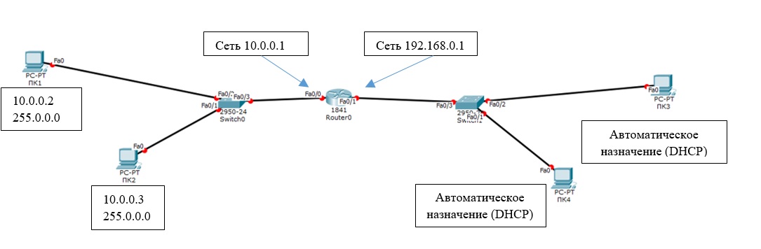
Общая сеть представляет из себя 2 сегмента (подсети 10.0.0.1/24 и 192.168.0.1/24), соединенных посредством маршрутизатора Cisco. Он будет осуществлять передачу данным между сетями в дуплексном режиме (прием и передача в обе стороны). К маршрутизатору (Router0) подключены 2 коммутатора. Интерфейс Fa 0/0 маршрутизатора подключен к порту Fa 0/3 левого коммутатора. С правым коммутатором (порт Fa 0/3) маршрутизатор подключен через интерфейс Fa 0/1. Switch0 будет осуществлять соединение ПК1 (Fa 0/2) и ПК2 (Fa 0/3), а ПК3 (Fa 0/2) и ПК4 (Fa 0/1) объединит Switch1. Порту Fa 0/0 маршрутизатора (слева) мы назначим адрес 10.0.0.1, а правому порту (Fa 0/1) – 192.186.0.1. На схеме мы видим, что все трассы (линии) подсвечены красным цветом. Это значит, что соединения нет и ни одно из устройств друг друга не «видят» в сети, потому что её ещё нет, а сетевые интерфейсы отключены (закрыты).
Настройки нашей сетей можно выполнить двумя способами:
- В графическом режиме
- В ручном режиме командами операционной системы Cisco IOS.
Левую половину сети будем настраивать графическим, а правую – ручным способами (изменения, которые мы вносим будут отражены выделены «жирным»).
Прежде всего начнем с графической настройки маршрутизатора (левая сторона):
- Щелкните левой кнопкой мыши по маршрутизатору Router0 -> Config -> FastEthernet0/0;
- Включите порт (Port Status – On);
- Присваиваем IP-адрес и маску подсети интерфейсу маршрутизатора FastEtherner0/0 (
10.0.0.0/ 255.255.255.0
);
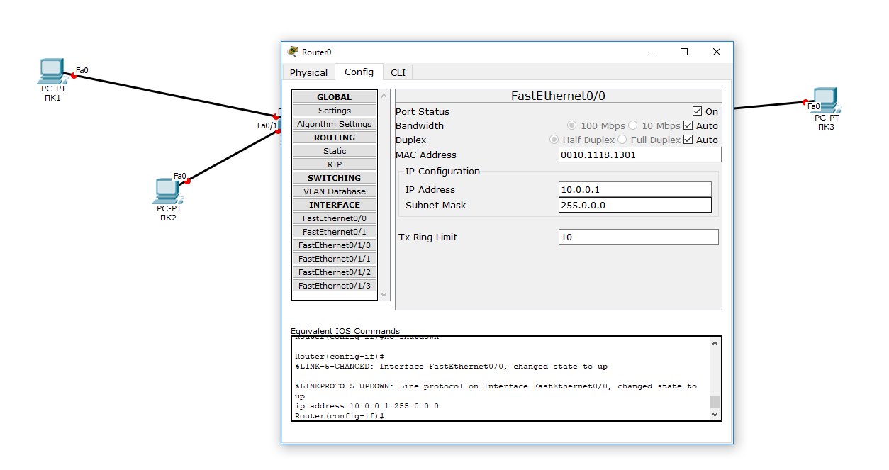
В ходе внесения нами изменений, автоматически формируется управляющая в окне Equivalent IOS Commands. В дальнейшем вы сможете использовать эти команды для ручной настройки маршрутизатора через команды CLI.
- Переходим к настройке FastEthernet 0/1 (правая часть);
- Включаем порт;
- Присваиваем IP адрес и маску (
192.168.0.1 255.255.255.0
).
Теперь настроим коммутатор (левый):
- Нажали 1 раз левой кнопкой мышки > Config > FastEthernet0/1;
- Включаем порт (Port Status – On);
- Точно также включаем порты 0/2 и 0/3.
Теперь мы видим, что соединение установлено (индикация на соединениях стала зелёного цвета).
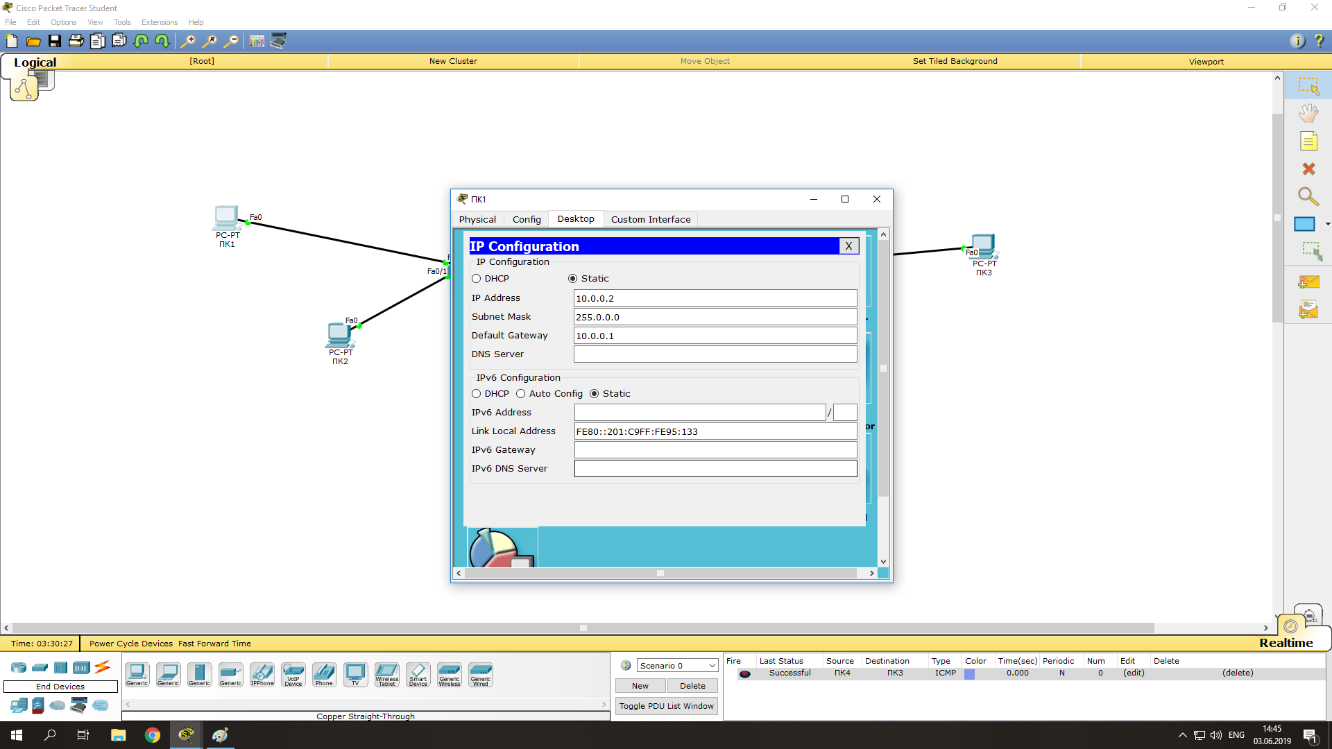
Зададим IP-адреса для компьютеров слева (в диапазоне указанных на маршрутизаторе адресов):
- Нажимаем на ПК1 левой кнопкой мыши -> Desktop -> IP Configuration;
- Указываем статический (опция Static) IP-адрес и маску, а также шлюз (Default Gateway – это будет IP адрес интерфейса Fa0/0 на маршрутизатор): IP:10.0.0.2 Mask:255.255.255.0 GW:10.0.0.1
- Нажимаем на ПК2 и производим аналогичные настройки, но с другим IP-адресом (10.0.0.3).
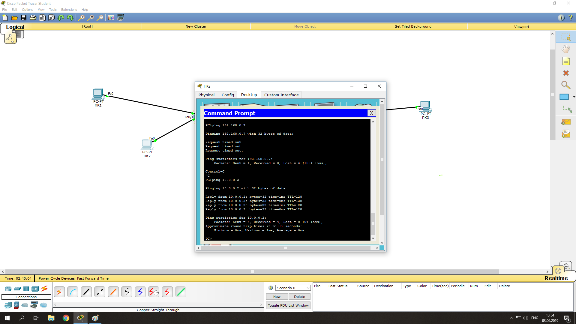
Проверим что оба компьютера стали доступны друг други (их пакеты проходят черех коммутатор):
- Нажимаем на ПК1 -> Desktop -> Command Prompt;
- В открывшемся окне командной строки, эмулирующей cmd выполните команду ping на ПК2:
ping 10.0.0.3
Соединение между ПК1 и ПК2 было установлено посредством логического соединения их через коммутатор. На этом графическая настройка левой части завершена.
Чтобы настроить правую часть сети, нужно только открыть порты на коммутаторе и назначить IP-адреса ПК3 и ПК4. Начнём с маршрутизатора. Ручная настройка несколько сложнее, нежели графическая, но на данном уровне она не составит особого труда. Приступим:
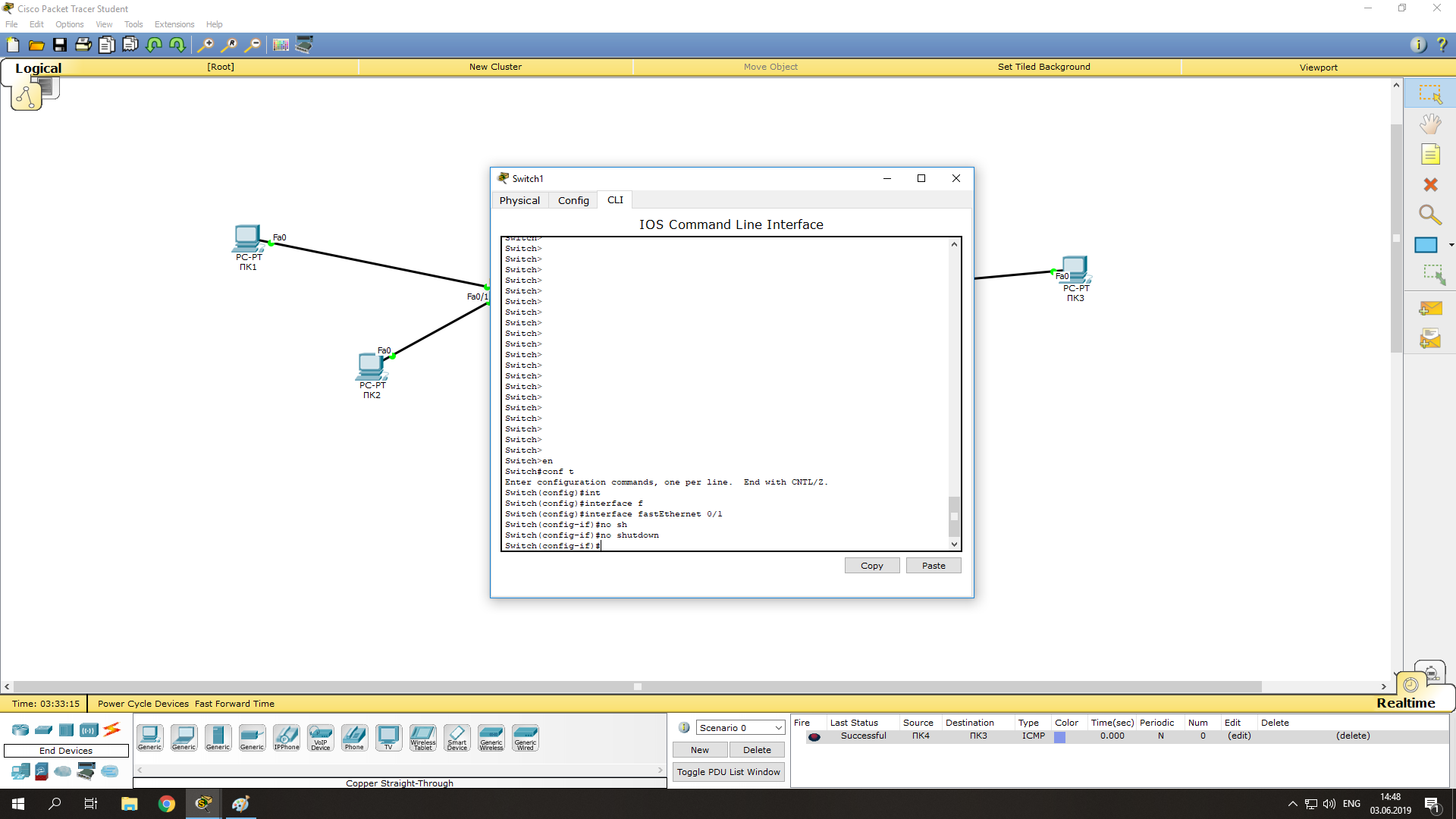
- Заходим на коммутатор -> CLI (командная строка коммутатора);
- Заходим в привилегированный режим (пишем
enable
или
en
); - Заходим в режим конфигурирования (
configure terminal
или
conf t
); - Нам нужно включить 3 интерфейса (FastEthernet 0/1-0/3), поэтому начнем с 0/1 (пишем
int f
и нажимаем tab, затем дописываем
0/1
, enter); - Мы зашли на интерфейс 0/1. Теперь активируем его (разрешим передачу данных по нему) командой
no sh
и нажимаем tab, потом enter. Теперь этот порт открыт (активен); - Выходим из настроек интерфейса командой
ex
и enter; - Такие же настройки произведите с портами FastEthernet 0/2 и 0/3.
Осталось лишь назначить IP-адреса компьютерам ПК3 и ПК4. Но мы усложним задачу и настроим автоматическое получение IP-адресов компьютерами по протоколу DHCP. В качестве DHCP сервера, который раздает IP адреса клиентам будет выступать маршрутизатор:
- Заходим на маршрутизатор -> CLI;
- Так как мы уже производили настройки графическим методом, то мы изначально находимся в привилегированном режиме. Переходим в режим конфигурирования (
conf t
); - Пишем
ip dhcp pool XXX
(XXX – название пула формирования адресов DHCP):
network 192.168.0.0 255.255.255.0
(из этой сети будут присваиваться наши IP-адреса компьютерам)
default-router 192.168.0.1
(указываем адрес маршрутизатора, который будет шлюзом по-умолчанию для компьютеров)
ex
(вышли обратно в режим конфигурирования)
ip dhcp excluded-address 192.168.0.1 192.168.0.5
(этот диапазон адресов будет исключен из раздачи, назначить IP-адрес из этого диапазона можно будет только вручную); - Заходим на ПК3 -> Desktop -> IP Configuration;
- Выбираем DHCP и смотрим на правильность назначенного IP адреса. В большинстве сетей IP адреса компьютерам назначаются именно так, путем получения настроек с DHCP сервера. Это исключает возможность конфликта IP-адресов, а также экономит время настройки.
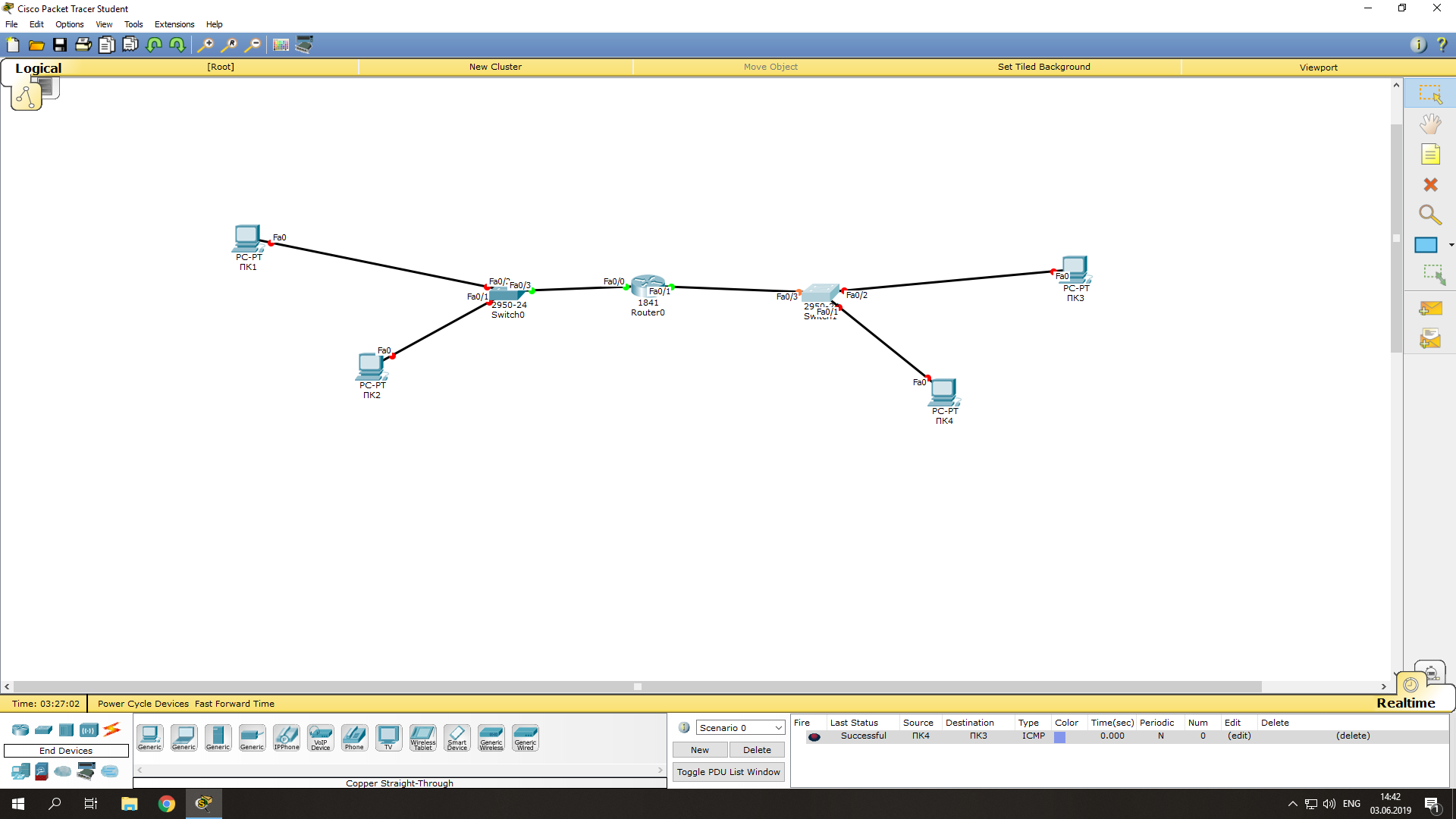
Проверяем соединение между компьютерами, соединёнными через маршрутизатор:
- Нажимаем на ПК3 -> Desktop -> Command Prompt;
- Выполняем ping на ПК1 и ПК2:
ping 10.0.0.2
ping 10.0.0.3
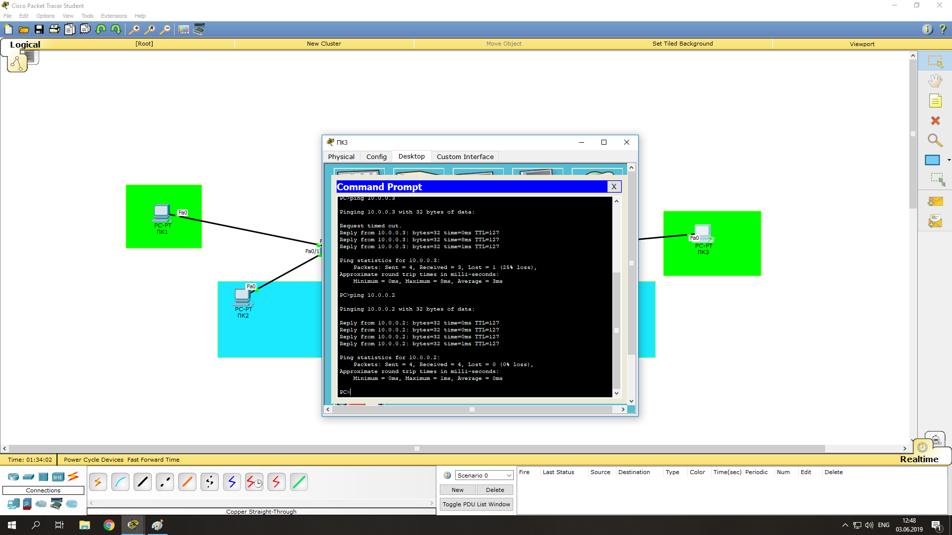
Теперь мы видим, что коммутация пакетов успешно установлена.
Усложним задачу. Свяжем между собой ПК1 и ПК2, а также ПК3 и ПК4. Выполнить эту задачу можно с помощью создания vlan (виртуальная локальная сеть). Она нужна для логического разграничения устройств. Так как мы не имеем возможности разделить сеть физически, воспользуемся vlan. Приступим:
- Создадим VLAN 10 на коммутаторах:
- Заходим на коммутатор (Switch0, затем также настраиваем и Switch1) -> CLI, пишем
conf t
vlan 10
(создался VLAN)
Interface FastEthernet 0/2
(для ПК1),
interface FastEthernet 0/1
(для ПК2),
interface FastEthernet 0/2
(для ПК3), или
interface FastEthernet 0/1
(для ПК4). Далее команды одинаковы для всех четырёх интерфейсов:
switchport mode access
switchport access vlan 10
Теперь ПК1 и ПК2 «общаются» в рамках своей сети, а ПК3 и ПК4, в рамках своей.
Вы можете получить текущую конфигурацию любого устройства в вашей сети, выполнив в CLI команду
show running-config
.
Итак, мы рассмотрели одну из самых простых схем типовой сети, использующейся для небольшой организации. Эта база, на которой строятся более сложные сети. Вы можете усложнить сеть путем добавления сетевого оборудования (дополнительные коммутаторы, маршрутизаторы, сервера, телефоны, беспроводные устройства и т.д.) и введением новых протоколов в работу (например, настройка IP-телефонов по протоколу SIP). Таким образом Cisco Packet Tracer будет отличным инструментом как для начинающего, так и для опытного сетевого инженера.
Configure A Router With Packet Tracer

Computer networking professionals getting started with Packet Tracer may find the interface to be flustered. Being a development program, this is only natural. However, learning how to configure a router with Packet Tracer will put professionals on the right track to mastering the program in about half an hour.
By this time, you should already have the Packet Tracer download and have it installed on your computer. Open the program and select the router from the lower left-hand corner, and drag it into the center of the sandbox screen as seen below. (Click for larger picture)

We will be setting up a very basic network that allows two computers to communicate, so the next step is to select end devices from the bottom left-hand corner and drag it to the sandbox screen. Do this twice to make two computers appear below the router.
Now select connections from the same bottom left-hand corner. When you connect like-devices(Such as a router and computer) you use a crossover cable, so you should select copper cross-over cable from the second menu to the immediate right. Click on Router0, and connect the cable via FastEthernet0/0 as seen below:

Now click the PC0 and select FastEthernet. You will notice that although a link is established, it is not functional. You can tell by the red dots that are present on both ends of the connection. Once the router is configured correctly, the red dots will turn green to indicate the devices are able to communicate.
Do the same operation to PC1, only this time connect the cable to FastEthernet0/1 since FastEthernet0/0 is already taken by PC0. Your network should be similar to the one below at this point:

Configuring The Router In Packet Tracer
A router that is turned off doesn’t work very well! Click on your router to bring up the configuration menu and verify that it is turned on.When on, there will be a small green light below the switch as seen in the diagram.

Next we have to open the Ethernet ports to allow communication. Although they are physically connected, they are in a state that is known as being in administrative shut down. Now click on the CLI tab to access the configuration menu. If you’ve used the Cisco IOS before, you will notice it looks and acts the same way.
1. Press RETURN to start the session
2. Type enable to get to privileged mode (this gives you more options in configuring the router)
3. Type config terminal (or config t for short) to access the configuration menu.
4. Type interface fastethernet0/0 to access Ethernet0/0
5. Type ip address 192.168.10.1 255.255.255.0 to assign an IP address and subnet mask to the interface.
6. Type no shutdown to open the interface up for business.
That’s it! You should now see a message similar to the following:
%LINK-5-CHANGED: Interface FastEthernet0/0, changed state to up
%LINEPROTO-5-UPDOWN: Line protocol on Interface FastEthernet0/0, changed state to up
Now we have to do the same thing for fastethernet0/1. If you don’t, there still won’t be a connection to PC1! Make sure to enter the IP address carefully as seen below:
1. Press Ctrl + Z to go back to the previous mode.
1. Type interface fastethernet0/1
2. Type ip address 192.168.20.1 255.255.255.0
3. Type no shutdown
At this point our router is configured properly. If you test out a ping, you will notice that the computers still don’t communicate, however!
Configuring The Gateway In Packet Tracer
Our last step is to configure the gateway on each desktop computer. The gateway is the address we assigned to the Ethernet port that the desktop is connected to. It will allow the computer to interface with another network, so our ping won’t work without it!
Click on PC0 to bring up the configuration menu. Under global settings you will find a field for the gateway. Enter the corresponding IP address of the router’s interface, which is 192.168.10.1. Then click the FastEthernet tab on the left column to set the actual computer’s IP address to be on the network. Use 192.168.10.2 for the IP address, and 255.255.255.0 for the subnet mask.

Do the same thing for PC1, only use 192.168.20.1 for the gateway address, 192.168.20.2 for the IP address, and 255.255.255.0 for the subnet mask. You can confirm that your network works by sending out a packet of information from PC0 to PC1, and vice versa. Click the packet icon on the right menu as seen below:

Click on PC0 and then click PC1. On the lower right of the screen you will see a message box that says “Successful.” If it doesn’t, you may have had a syntax error when putting in an IP address or router configuration command. Review your work or ask for help among the community if you are stuck.
Closing Comments
Congratulations! You have a small working network. A real-world application of this very network would be to have two computers connected to the Internet, whereas the router would then be connected to your telecommunications company. (Or what we would call the “cloud”)
More advanced devices and topologies won’t be so easy, but you’re now on the right path to becoming qualified for the CCNA certification exam.
About The Author

Alison Quine
Configure
IP address to Router and PC in Packet Tracer
- As a Network Engineer, it is compulsory to
know how to configure an IP Address on networking devices like Router, Switch,
PC, and Server. - Assigning an IP address to a device is a
foundational requirement for all Cisco networking devices. - Networking devices communicate with each
other with the help of IP address that configures on an individual device.
Router
Interfaces
- The interface configuration is one of the
most important router configurations because, without interfaces, a router does
not communicate with other devices on a network. - Router interfaces also play a great role in
troubleshooting, which often results in solving the connectivity problem by
correcting the misconfigured interfaces of the router.
Configure an IP Address on Router’s Interface
There are two ways to configure an IP Address on the
Router’s Interface-
- Configure an IP Address to Fast Ethernet
Interface - Configure an IP Address to Serial Interface
Configure an IP Address to Fast Ethernet Interface
There are following steps involved to configure an IP
Address to Fast Ethernet Interface –
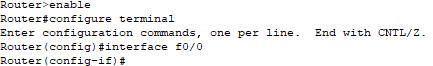
Step1: Open
the Cisco Packet Tracer.
Step2:
Drag
and drop any series of the router from the bottom of the interface into the
middle of the working area.
Step
3: Select
cable from the bottom of the interface to connect the routers.
Step
4: Click
on Router R0, then on CLI.
Step5: Go to the global configuration mode, and type slot/ port or interface Fast Ethernet 0/0 (or interface f0/0)
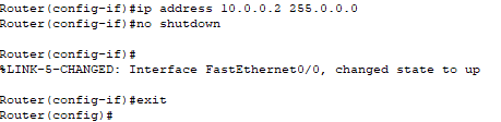
Step
6: Now
configure an IP address and subnet mask then give “no shutdown” command. (In our case, IP address is 10.0.0.2 and
subnet mask is 255.0.0.0)
Note:
Carefully
configure IP address with proper interfaces.
Configure an IP Address to Serial Interface
There are following steps involved to configure an IP
Address to Serial Interface –
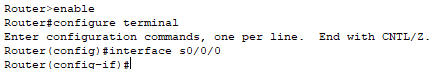
Step1:
Open
the Cisco packet tracer.
Step2:
Drag
and drop any series of the router from the bottom of the interface into the
middle of the working area.
Step
3:
Click the Router ->select then Physical->select then WIC-IT->switch
off the router.
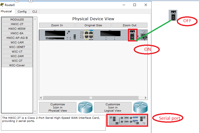
- Add serial port -> Switch ON the router.
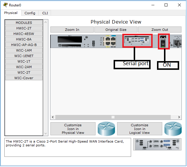
- Now Go to CLI, then the global configuration
mode, and type interface serial 0 0/0 (or interface s0/0/0).
- Now, configure an IP address and subnet mask,
and then give no shutdown command.
(In our case IP address is 10.0.0.2 and subnet mask is 255.0.0.0)
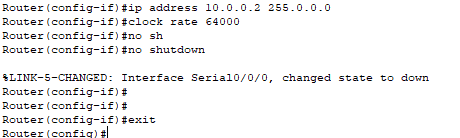
Note: Carefully configure IP address with proper interfaces.
Configure an IP Address to PC
There are following steps involved to configure an IP
Address to PC:
Step1: Open
the Cisco Packet Tracer.
Step2:
Drag
and drop PC from the bottom of the interface into the middle of the working
area.
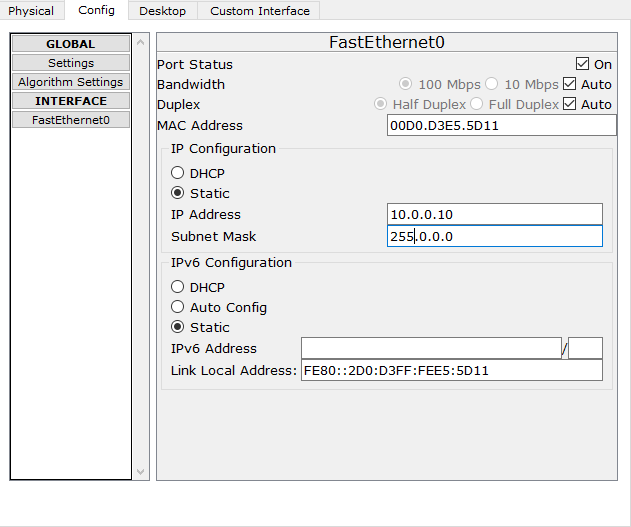
Step3:
Click
on PC ->Config Gateway like 10.0.0.1
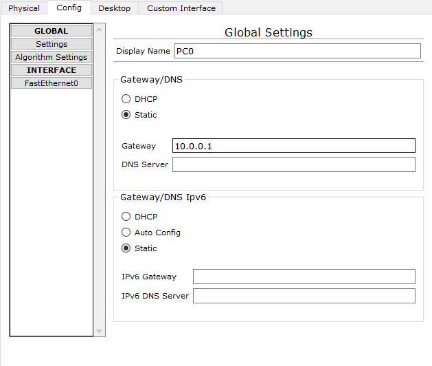
Click on FastEthernet to assign an IP address and subnetmask to the PC, and close PC window. In our case IP is 10.0.0.10 and subnet mask is 255.0.0.0.0,
- Configuring Catalyst Switches
- Configuring IP Routing in Our Network
- Checking Network Connectivity and Troubleshooting
- Saving, Erasing, and Verifying Configuration
- OSI Reference Model
- Internetworking Basics
- Configure Password
- Configure Hostname
- Configuring OSPF
- Configuring EIGRP