In this DHCP Cisco Packet Tracer router example, we will focus on DHCP Configuration in Cisco Packet Tracer. In other words, we will see how to configure a DHCP Server with Packet Tracer Router. Before start up I want to give some basic information about DHCP.
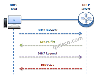
As you know DHCP uses UDP 67 and UDP 68 ports. It has a messaging system for the communication between DHCP Server and DHCP Client. These messaging system’s messages and their types are mentined below:
- DHCP Discover (broadcast)
- DHCP Offer(broadcast)
- DHCP Request (broadcast)
- DHCP Ack (broadcast)
- DHCP Nak (unicast)
- DHCP Release (unicast)
- DHCP Decline (unicast)
- DHCP Inform (unicast)
 DHCP Messages
You can Reach All Cisco Packet Tracer Labs and DOWNLOAD the Packet Tracer Examples with .pkt format.
You can DOWNLOAD this lessons Packet Tracer Example with .pkt format HERE.
- Firstly, a client sends a broadcast “DHCP Discovery” message that mentions that it need an ip address.
- Then, the DHCP servers reply with configuration offers to the client by “DHCP Offer” unicast message
- After that DHCP client sends a broadcast “DHCP Request” message to the network with the “Transaction ID” of the first DHCP Server that send Offer. The other servers understand that client wants to use the server that has the related “Transaction ID”.
- Lastly, the Server sends a unicast “Acknowledgement” message to the client that mentions the ip assignment is successfully done or it send a refuse messaged named “DHCP-NACK”.
To configure a Packet Tracer Router ’s DHCP, we must follow some basic steps. For this configuration the important point is broadcast domains. If we have only one broadcast domain in our topology, our work is simpler, else we must get help from “ip-helper address” command.
What is ip helper address command? Ip helper address command is the command that helps us to convince the router and make it pass the broadcast packets.
Now, let’s go to our two different configuration topology and see how to configure a server in packet tracer for DHCP, how to configure a DHCP Server in packet tracer.
Table of Contents
DHCP Packet Tracer Config For One Broadcast Domain
Our one broadcast domain topology is like below. There is a router that will carry our DHCP server role beside its routing functionalities. And there is a switch for PCs.
 DHCP Example Topology (One Broadcast Domain)
Firstly, let’s see How to Configure a DHCP Server on a Packet Tracer Router for One Broadcast Domain. For this first case of our DHCP Cisco packet tracer example, the One Broadcast Domain topology that we will use, is like below. There is a router that will carry out Server role beside its routing functionalities. And there is a switch for PCs.
On routerA, firstly we will give an ip address to the router interface that is connected to the switch.Secondly that we will create a DHCP pool named IPD. In this pool we will mention ip addresses that will be given to the DHCP clients. After that we will assign the router’s interface address as a default-router address for clients. And in the last part, we will exclude some addresses with “ip dhcp excluded address” command, that we don’t want to use during this dynamic ip assignments. With “ip dhcp excluded address” command, the mentined addresses will not used in the pool.
RouterA# config terminal
RouterA(config)# interface fastEthernet 1/0
RouterA(config-if)# ip address 192.168.10.1 255.255.255.0
RouterA(config-if)# no shut

%LINK-5-CHANGED: Interface FastEthernet1/0, changed state to up
%LINEPROTO-5-UPDOWN: Line protocol on Interface FastEthernet1/0, changed state to up<
RouterA(config-if)# exit
RouterA(config)# ip dhcp pool IPD
RouterA(dhcp-config)# network 192.168.10.0 255.255.255.0
RouterA(dhcp-config)# default-router 192.168.10.1
RouterA(dhcp-config)# exit
RouterA(config)# ip dhcp excluded-address 192.168.10.1 192.168.10.10
RouterA(config)# ip dhcp excluded-address 192.168.10.12 192.168.10.14
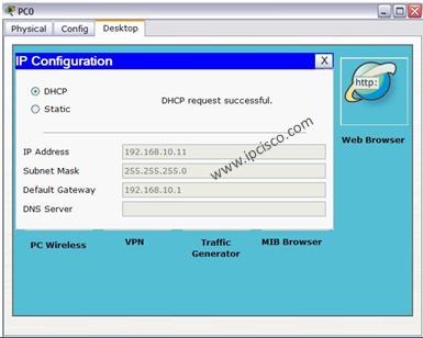
After this configuration, when we check the ip address of PC0, we will see the ip address 192.168.10.11 . Because it is the first available address in DHCP pool.
 We can also check the pool information with Cisco “show ip dhcp pool” command.
Packet Tracer DHCP Config For Multiple Broadcast Domains
Our second case is how to enable DHCP on router for multiple broadcast domains. In our second Cisco packet tracer example, we will use ip helper, cisco command “ip helper-address“. So, what is ip helper address?
Many CCNAs learn that routers do not pass broadcasts. But progress in CCIE, network engineers learn that it is not true. Because you can pass broadcast traffic for many protocols as DHCP by “ip-helper address” command. Here we will refer only the broadcast of DHCP requests. We can use a router as a DHCP Server again, but I use a separate DHCP Server instead of router in this topology.
") DHCP Example Topology (Multiple Broadcast Domains)
DHCP Example Topology (Multiple Broadcast Domains)
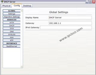
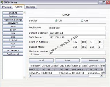
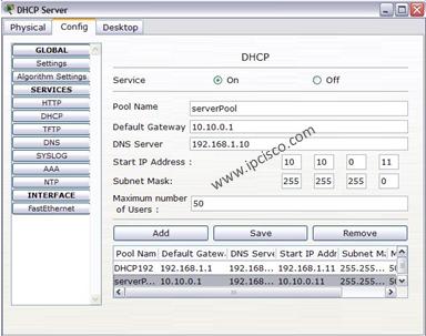
In the first place we will configure the DHCP Server for its DHCP pools and its ip configuration. The ip address is 192.168.1.10 and the default gateway will be the routers interface’s ip address that is face to DHCP server.
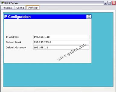
For the subnets 192.168.1.0 and 10.10.0.0 there must be two DHCP pool.The below screenshot is showing how these assignments will be done in DHCP Server.
In the Packet Tracer router the following configuration will be done for two different subnet DHCP achivement:
RouterC # config terminal
RouterC(config)# interface fa0/0
RouterC(config-if)# ip address 10.10.0.1 255.255.255.0
RouterC(config-if)# ip helper-address 192.168.1.10
RouterC(config-if)# no shutdown
RouterC(config-if)# exit
RouterC(config)# interface fa1/0
RouterC(config-if)# ip address 192.168.1.1 255.255.255.0
RouterC(config-if)# ip helper-address 192.168.1.10
RouterC(config-if)# no shutdown
RouterC(config-if)# end
RouterC# copy run start
After this configuration, we can try dynamic ip assignment on PC by selecting the dynamic option on ip configuration screen like below.
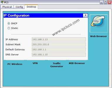
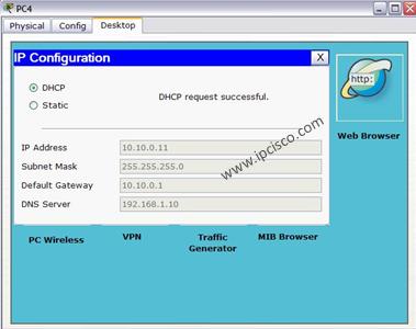
As you can seee, our PCs get their IP configuration from DHCP Server. The IP assignment is done automatically.

DHCP Messages
Packet Tracer Router Configuration Basics
Here, I would like to give you some information about how to configure a Cisco router on Packet Tracer basically. This is not a part of DHCP Configuration, but they are essentials for router configuration. So, here, we will learn how to set our laptop to connect a router, how to change a router’s name, how to set passwords on the Cisco routers, how to set console Access and basic static routing configuration step by step.
Laptop Configuration to Connect a Router
In Cisco Packet Tracer, you can directly click routers and connect them. But if you would like to do this via Console connection with a laptop with console cable as in real world, you can do it with a laptop and router. To do this, you need to set laptop terminal software setting and then a console cable to connect laptop and router.
When you click laptop on cisco packet tracer, you will see some tabs. In the desktop tab, there is a terminal configuration. When you click it, you will see the terminal settings. If you would like to connect to a router, you should set the settings as below:
Bits Per Second: 9600
Data Bits: 8
Parity : None
Stop Bits : 1
Flow Control : None
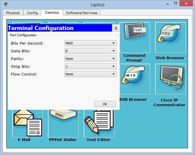
After setting these configurations, you will be ready to connect your router in packet tracer.
How to start configuration on a Cisco router?
In all routers, there are special configuration commands to start the router configuration. In Cisco routers this is also a standard. To start to configure a router on packet tracer, we should use firstly “enable” command. This will give us an administrator privilege and then we will use “configure terminal” to start our packet tracer router configuration. You can use this long version or you can use even “conf t” to do this.
Router> enable

Router# configure terminal
Enter configuration commands, one per line.  End with CNTL/Z.

Router(config) #
How to Configure Router Name?
All routers have a default name. But generally, this name is changed to have more meaningful router names. These router names can show the location of a router, its level, importance etc. With one or more word, we can give a special name to the routers on packet tracer.
To give a router name to a Cisco router on packet tracer, we use “hostname” commands. We can use this command in configuration mode of Cisco routers. Here, we can set our router’s name as XYZ
Router(config)# hostname XYZ
How to Configure Enable Secret Password?
To secure our router, firstly we should give a password to this router. There are different passwords used in Cisco routers. One of the basic passwords used in routers is “enable password”. This is the password that keeps the password as clear text. But there is also another password called “enable secret password”. This password keeps passwords with MD5 and it is more secure. You can see the value of enable password clearly in configuration, but you can not see enable secret password in configuration.
Here, let’s configure our enable secret password as abc123.
XYZ (config)# enable secret password abc123
By the way the command to encrypt passwords is “service password-encryption”. We will use this command to encrypt our passwords.
XYZ (config)# service password-encryption
How to Configure Console Access on Cisco Routers?
Console connection is need to be done before your connection. It is the basic router configuration that is required to connect to the router with a laptop.
We use “line console 0” command to access console configuration. We will determine a password, let’s do it as abcdef. After that we will use “login” keyword.
XYZ (config)# line console 0

XYZ (config-line) # password abcdef

XYZ (config-line) # login
Beside this basic console configuration, there are also some other configuration steps under this console access that will help you during our packet tracer router configuration a lot. These commands are:
- logging synchronous
- exec-timeout
- history size
With logging synchronous, we can set console synchronization to avoid command corruption. If we do not use this command, router can print some outputs during we are entering the commands and after a while this can be annoying.
XYZ (config-line) # logging synchronous
Exec timeout is the command that is used to adjust router timeout. This can be set with minutes and seconds. If you do not want any timeout, you can use 0 with this command. Here, we will use 3 minutes 30 seconds. After this period, if there is no action, router will go to the timeout. By the way the default timeout time is 10 minutes for Cisco routers.
XYZ (config-line) # exec-timeout 3 30
The last command is related with the command history. We can set the last remembered commands with history command. Here, we will set is as 20 commands.
XYZ (config-line) # history 20
How to Set Interface IP Addresses on Cisco Routers?
One of the most important and mostly done configuration is interface configurations on the routers. So, how to give an ip address and activate an interface of a Cisco router? We will use “ip address” command with the name of the interface on the routers. Here, let’s configure GigabitEthernet 0/0 of the router with the ip address 192.168.0.5/24.
XYZ (config) # interface GigabitEthernet 0/0
XYZ (config-if) # ip address 192.168.0.5 255.255.255.0
XYZ (config-if) # no shutdown
All the interfaces of the routers are shutdown by default. So, to open these ports, we should use “no shutdown” command.
After this configuration, our port can be up or down according to the other end. If there is no problem at the other end and there is configuration, then our port will be up.
How to Configure Static Routing on Cisco Routers?
Static Routing is the simplest and most used routing type on routers. Sometimes we need to use static routing in packet tracer router configurations. So, here, we will see how to configure static routing basically.
For static routing we will use “ip route” command with the destination network, subnet mask and the gateway that we will go firstly to access this network. Think about that, we should access 10.0.0.0/24 network and our gateway to access this network is 172.16.0.1. So, our static routing configuration will be like below:
XYZ (configf) # ip route 10.0.0.0 255.255.255.0 172.16.0.1
Basic Packet Tracer Router Verification Commands
After basic configurations, you can check your configurations with basic router verification commands. Some of these commands are given below:
- show startup-config
- show running-config
- show interfaces
- show ip route
show startup-config shows the beginning configuration that is stored in NVRAM.
show running-config shows current configuration. It is stored in RAM.
With show interfaces command, you can check the status and the configurations of the interfaces.
With show ip route command, you can see the routing information both static routing and dynamic routing.
There are many other show commands used in routers. You will be familiar with all of these with more practice on Cisco Packet Tracer. In the following lessons, we will see all these commands one by one.

Hello and welcome! This tutorial will guide you on how to configure a DHCP server both on a router and on a generic server in Cisco Packet Tracer. In both cases, configuration is simple as long as you have a basic knowledge of IP addressing. On to it then!
Configuring DHCP server on a Router.
- Build the network topology:

2. On the router, configure interface fa0/0 to act as the default gateway for our LAN.
Router>enable
Router#config terminal
Router(config)#int fa0/0
Router(config-if)#ip add 192.168.1.1 255.255.255.0
Router(config-if)#no shutdown
Router(config-if)#exit
3. Configure DHCP server on the Router. In the server we will define a DHCP pool of IP addresses to be assigned to hosts, a Default gateway for the LAN and a DNS Server.
Router(config)#
Router(config)#ip dhcp pool MY_LAN
Router(dhcp-config)#network 192.168.1.0 255.255.255.0
Router(dhcp-config)#default-router 192.168.1.1
Router(dhcp-config)#dns-server 192.168.1.10
We can add ip dhcp excluded-address command to our configuration so as to configure the router to exclude addresses 192.168.1.1 through 192.168.1.10 when assigning addresses to clients. The ip dhcp excluded-address command may be used to reserve addresses that are statically assigned to key hosts.
So add the above command under the global configuration mode.
Router(config)#ip dhcp excluded-address 192.168.1.1 192.168.1.10
4. Now go to every PC and on their IP configuration tabs, enable DHCP. Every PC should be able to obtain an IP address, default gateway and DNS server, as defined in step 2.
For example, to enable DHCP on PC1:
Click PC1->Desktop->IP configuration. Then enable DHCP:

Do this for the other PCs.
You can test the configuration by pinging PC2 from PC1. Ping should succeed.
It’s that simple!
Now let’s do the same thing using a Generic server in place of a router:
Configuring DHCP service on a generic server in Packet Tracer.
1. Build the network topology in packet tracer

2. Configure static IP address on the server (192.168.1.2/24).
3. Now configure DHCP service on the generic server.
To do this, click on the server, then click on Services tab. You will pick DHCP on the menu. Then proceed to define the DHCP network parameters as follows:
Pool name: MY_LAN
Default Gateway: 192.168.1.1
DNS Server: 192.168.1.2
Start IP Address: 192.168.1.0
Subnet Mask: 255.255.255.0
Maximum Number of users: 256
Click on add then Save.The DHCP entry is included in the list.
Here are the configurations on the server:

Once you’ve configured everything, turn ON the DHCP service.
4. Finally, enable DHCP configuration on each PC. The three PCs should get automatically configured.
As an example, here is the DHCP configuration on PC1:

Addendum: You can define a DHCP server on one broadcast domain to serve hosts in a different broadcast domain. If you want to do this, then you should consider using ip helper-address command. To learn more about this, you can read my article on IP helper address configuration.
Success! Success!
Hope you found this post helpful. Comment to help improve it.
You may also like to read:
- Configuring DHCPv6 (both stateless and stateful) in Packet Tracer.
- Basic IPv6 configuration in Packet Tracer.
- DNS server configuration in Packet Tracer.
- HTTP server configuration in Packet Tracer.
- Mail server configuration in Packet Tracer.
With Cisco Packet Tracer, you can create network topologies and gain experience. This software is a network simulator program from Cisco and is completely free.

How to Enable and Configure DHCP on a Cisco Router
The easiest way to configure a network is to take advantage of DHCP servers located on routers. The DHCP server is responsible for providing an IP address and network parameters (subnet mask and gateway) to all equipment and devices connected to it.
This server is also responsible for configuring the DNS servers of the connected equipment, but because of the firmware installed by the providers on their routers, the DNS added by default is the manufacturer’s DNS.
Dynamic Host Configuration Protocol is the protocol that allows the automatic assignment of IP addresses.
The DHCP protocol uses UDP as the transport protocol, UDP port 67 is the destination port of a server, and the client uses UDP port 68.
With the DHCP service, you can configure the following parameters automatically:
- IP Address
- Subnet Mask
- Default Gateway
- DNS
By using Cisco’s network simulator software to create a new network topology and add multiple clients and one Cisco Router to the network, you can automatically configure it with the DHCP service instead of manually configuring the TCP/IP configuration of all clients that will be connected to the network.
Step 1
First, create a network topology with two separate segments (192.168.1.0/24 and 192.168.2.0/24) in Packet Tracer.

Step 2
In the Router0 window, click the CLI command prompt tab and in the initial configuration screen, type No and press Enter. If you select Yes on this screen, the Cisco router will ask you step-by-step to make basic settings.

Step 3
Assign IP addresses and open ports to Cisco router interfaces according to the network topology you create. Then, enable DHCP by executing the following commands to automatically distribute IP information from the Router to the clients.
Router>enable
Router#conf t
Enter configuration commands, one per line. End with CNTL/Z.
Router(config)#interface gigabitethernet 0/0
Router(config-if)#ip address 192.168.1.1 255.255.255.0
Router(config-if)#no shutdown
%LINK-5-CHANGED: Interface GigabitEthernet0/0, changed state to up
%LINEPROTO-5-UPDOWN: Line protocol on Interface GigabitEthernet0/0, changed state to up
Router(config-if)#exit
Router(config)#interface gigabitethernet 0/1
Router(config-if)#ip address 192.168.2.1 255.255.255.0
Router(config-if)#no shutdown
%LINK-5-CHANGED: Interface GigabitEthernet0/1, changed state to up
%LINEPROTO-5-UPDOWN: Line protocol on Interface GigabitEthernet0/1, changed state to up
Router(config-if)#exit
Router(config)#ip dhcp pool LAN1
Router(dhcp-config)#network 192.168.1.0 255.255.255.0
Router(dhcp-config)#default-router 192.168.1.1
Router(dhcp-config)#dns-server 192.168.1.1
Router(dhcp-config)#exit
Router(config)#ip dhcp excluded-address 192.168.1.1
Router(config)#ip dhcp pool LAN2
Router(dhcp-config)#network 192.168.2.0 255.255.255.0
Router(dhcp-config)#default-router 192.168.2.1
Router(dhcp-config)#dns-server 192.168.2.1
Router(dhcp-config)#exit
Router(config)#ip dhcp excluded-address 192.168.2.1
Router(config)#end
Router#
%SYS-5-CONFIG_I: Configured from console by console
Router#wr
Building configuration...

Router#

Step 4
After you apply the Cisco DHCP commands, you must set up the computers that you add to the Packet Tracer workspace for the automatic IP address. To do this, click on PC0, click IP Configuration in the window that opens, and then activate the DHCP option.

Step 5
After enabling DHCP on PC0, an IP address request will be sent as in the following image.

Step 6
DHCP will allocate an IP address by responding to PC0’s request.

Step 7
Enable the DHCP option for computers on the 192.168.2.0/24 network and check the status.

Step 8
PC2 will also obtain the IP address successfully because the DHCP pool is configured for the 192.168.2.0/24 network on the Cisco router.

Step 9
When you test the network connection by pinging PC0 to 2.0, this will be successful as follows.

Step 10
Ping over PC3 to the 1.0 network will also be successful.

Step 11
You can see the IP addresses and MAC addresses assigned to the clients with the show ip dhcp binding command on the router.

Step 12
You can also review the DHCP pool details as shown in the image below when you execute the show ip dhcp pool command.

Show Commands
Router#show ip dhcp ?
binding DHCP address bindings
conflict DHCP address conflicts
pool DHCP pools information
relay Miscellaneous DHCP relay information
Router#show ip dhcp binding
IP address     Client-ID/                      Lease expiration    Type
Hardware address
192.168.1.2 000C.8536.A381           --                           Automatic
192.168.1.3 00E0.B0AC.5779           --                           Automatic
192.168.2.2 00E0.F7CA.7827           --                           Automatic
192.168.2.3 000A.F383.BCDE           --                           Automatic
Router#show ip dhcp pool

Pool LAN1 :
Utilization mark (high/low) : 100 / 0
Subnet size (first/next) : 0 / 0
Total addresses : 254
Leased addresses : 2
Excluded addresses : 2
Pending event : none

1 subnet is currently in the pool
Current index IP address range Leased/Excluded/Total
192.168.1.1 192.168.1.1 - 192.168.1.254 2 / 2 / 254

Pool LAN2 :
Utilization mark (high/low) : 100 / 0
Subnet size (first/next) : 0 / 0
Total addresses : 254
Leased addresses : 2
Excluded addresses : 2
Pending event : none

1 subnet is currently in the pool
Current index IP address range Leased/Excluded/Total
192.168.2.1 192.168.2.1 - 192.168.2.254 2 / 2 / 254
Router#
Video
PT yazılımını kullanarak Cisco yönlendirici üzerinde DHCP’yi yapılandırmak için aşağıdaki videoyu izleyebilir ve ayrıca bize destek olmak için YouTube kanalımıza abone olabilirsiniz!
Final Word
In growing network topology, manually configuring the TCP/IP settings of network devices will save you time by adding a DHCP Server to the environment to automatically distribute IP information to clients or activate the server on the Router you are using. Thanks for following us!
Related Articles
♦ DHCP Relay Agent
♦ Windows Packet Tracer
♦ Cisco Telnet Settings
♦ Cisco Router Console
♦ Cisco SSH Settings

TolgaBagci
Hello, I’m Tolga! I am a computer specialist who has been specializing in computer technologies for about 20 years. I provide solutions to problems encountered in many areas such as hardware, system, network, virtualization, server systems, and operating systems, and create relevant content on my website by explaining how to solve these problems. My goal is to be a reliable source of expert, quality, and trustworthy solutions for your computer problems. By following innovations and using the latest technologies, I aim to be successful in my job and provide you with the best service. Don’t hesitate to contact me for any questions or curiosity about technology. Have a nice day, stay up to date 
Pre-requisite : Dynamic Host Configuration Protocol (DHCP), Basics of Wi-Fi.
DHCP is based on a client-server model, based on discovers, offers, requests, and ACKs. The DHCP port number for the server is 67 and for the client is 68. This is a client/server protocol using UDP services. IP addresses are assigned from a pool of addresses. In DHCP, clients and servers exchange four main DHCP messages to establish a connection. Also called the DORA process, there are eight DHCP messages in the process.
Configure DHCP on Wireless Router:
Step 1: Create the topology in CPT as shown in the image below :

- From the bottom toolbar, click on ‘End Devices’ and select ‘PC’ and then drag it to the workspace.

- Now select ‘Laptop’ and drag it to the workspace.
- From the bottom toolbar, click on ‘Network Devices’ and under ‘Wireless Devices’, select “Home Router” and drag it to the workspace.

Step 2: Configure DHCP on Home-Router-PT-AC :
- Click on the Home Router device.
- A dialogue box will appear then click on “Config” tab.
- From the side menu bar, click on “LAN” and configure LAN settings as shown in the image below :Cl

- Click on “GUI” tab and configure the basic setup as shown in the image below :

Step 3: Click on the PC and under physical tab, change the module of the PC as follows :
- Turn off the PC.
- Change the default module with the WMP300N module which is a 2.4 GHz wireless interface for connecting to wireless network.

Step 4: Click on Laptop and under physical tab, change the module of the Laptop as follows :
- Turn off the Laptop.
- Change the default module with the WPC300N module which is a 2.4 GHz wireless interface for connecting to wireless network.

Step 5: After completing the above steps, the end devices (PC and Laptop) will automatically connect to the wireless network configured on the Home router device and request for the IPv4 address and the topology will look like this :

Step 6: Verify IP configuration and connectivity throughout the topology :
- Click on the PC and under the “Desktop” tab click on “Command Prompt” and check IP configuration with the command :
C:\>ipconfig

- Now, check the connectivity with other devices in the topology by pinging them :
C:\>ping 192.168.1.1
C:\>ping 192.168.1.101

Simulation Result:

- Click on the Laptop and under the “Desktop” tab click on “Command Prompt” and check IP configuration with the command :
C:\>ipconfig

C:\>ping 192.168.1.1
C:\>ping 192.168.1.100

Simulation Result:

Last Updated :
13 Nov, 2022
Like Article
Save Article
DHCP is an Internet control protocol used to assign an IP address to any appliance, or node, on an internet network so they can transmit data using IP. DHCP automatically handles these configurations rather than requiring network administrators to manually set IP addresses to all network devices. DHCP can be executed on small local networks, as well as large company networks.
To know more about DHCP you may refer to the article Dynamic Host Configuration Protocol (DHCP).
Steps:
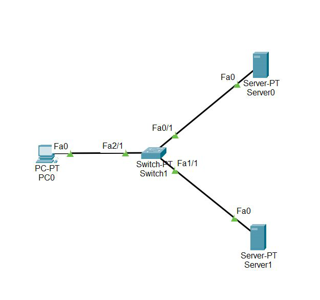
Step 1: First, open the cisco packet tracer desktop and select the devices given below:
| S.NO | Device | Model Name | Qty. |
|---|---|---|---|
| 1. | PC | PC | 1 |
| 2. | switch | PT-switch | 1 |
| 3. | server | Server-PT | 2 |
IP Addressing Table
| S.NO | Device | IPv4 Address | Subnet Mask | Default Gateway | DNS |
|---|---|---|---|---|---|
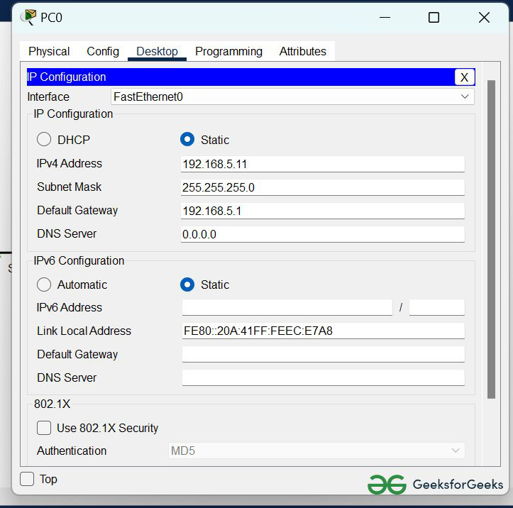
| 1. | PC0 | 192.168.5.11 | 255.255.255.0 | 192.168.5.1 | nil |
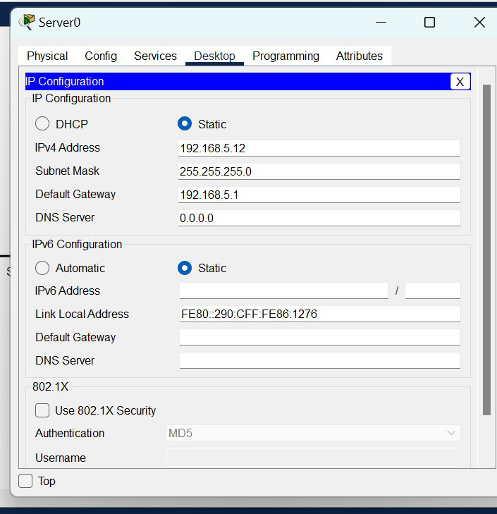
| 2. | server0 | 192.168.5.12 | 255.255.255.0 | 192.168.5.1 | nil |
| 3. | DNS | 192.168.5.13 | 255.255.255.0 | 192.168.5.1 | 192.168.5.13 |
- Then, create a network topology as shown below the image.
- Use an Automatic connecting cable to connect the devices with others.
Step 2: Configure the PCs (hosts) Server0 and DNS with IPv4 address and Subnet Mask according to the IP addressing table given above.
- To assign an IP address, click on the device.
- Then, go to desktop and IP configuration and there you will find IPv4 configuration.
- Fill IPv4 address and subnet mask and other inputs.

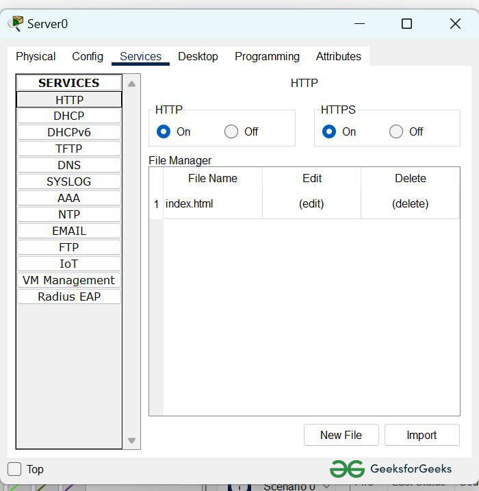
Step 3: Configure the HTTP sever0
- To configure the HTTP server.
- Go to services then click on HTTP
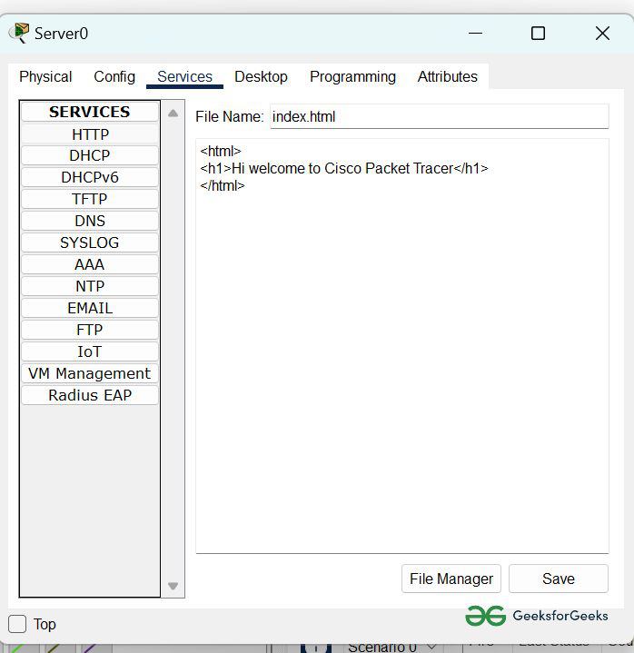
- Then delete all of the files except the index.html and edit it.
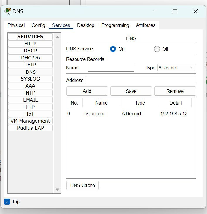
Step 4: Configure the DNS server
- To configure the DNS server.
- Go to services then click on DNS.
- Then turn on the DNS services.
- Name the server cisco.com and type address 192.168.5.12
- And add the record.
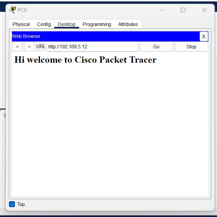
Step 5: Verify the server by using the web browser in the Host.
- Enter the IP address of server0 and click on GO.
- It will show the results.
Last Updated :
24 Jun, 2022
Like Article
Save Article