Basic IP Routing
This module describes how to configure basic IP routing. The Internet Protocol (IP) is a network layer (Layer 3) protocol
that contains addressing information and some control information that enables packets to be routed. IP is documented in RFC
791 and is the primary network layer protocol in the Internet protocol suite.
Finding Feature Information
Your software release may not support all the features documented in this module. For the latest caveats and feature information,
see Bug Search Tool and the release notes for your platform and software release. To find information about the features documented in this module,
and to see a list of the releases in which each feature is supported, see the feature information table.
Use Cisco Feature Navigator to find information about platform support and Cisco software image support. To access Cisco Feature
Navigator, go to www.cisco.com/go/cfn. An account on Cisco.com is not required.
Information About Basic IP Routing
Variable-Length Subnet Masks
Enhanced Interior Gateway Routing Protocol (EIGRP), Intermediate System-to-Intermediate System (IS-IS), Open Shortest Path
First (OSPF), Routing Information Protocol (RIP) Version 2, and static routes support variable-length subnet masks (VLSMs).
With VLSMs, you can use different masks for the same network number on different interfaces, which allows you to conserve
IP addresses and more efficiently use available address space. However, using VLSMs also presents address assignment challenges
for the network administrator and ongoing administrative challenges.
Refer to RFC 1219 for detailed information about VLSMs and how to correctly assign addresses.

Note |
Consider your decision to use VLSMs carefully. You can easily make mistakes in address assignments and you will generally |
The best way to implement VLSMs is to keep your existing addressing plan in place and gradually migrate some networks to
VLSMs to recover address space.
Static Routes
Static routes are user-defined routes that cause packets moving between a source and a destination to take a specified path.
Static routes can be important if the device cannot build a route to a particular destination. They are also useful for specifying
a gateway of last resort to which all unroutable packets will be sent.
To configure a static route, use the
ip route
prefix mask {ip-address |
interface-type interface-number [ip-address]} [distance] [name] [permanent |
track
number] [tag
tag] global configuration command.
Static routes remains in the device configuration until you remove them (using the
no ip route global configuration command). However, you can override static routes with dynamic routing information through prudent assignment
of administrative distance values. An administrative distance is a rating of the trustworthiness of a routing information
source, such as an individual router or a group of routers. Numerically, an administrative distance is an integer from 0 to
255. In general, the higher the value, the lower the trust rating. An administrative distance of 255 means the routing information
source cannot be trusted at all and should be ignored.
Each dynamic routing protocol has a default administrative distance, as listed in the table below. If you want a static route
to be overridden by information from a dynamic routing protocol, simply ensure that the administrative distance of the static
route is higher than that of the dynamic protocol.
|
Route Source |
Default Distance |
|---|---|
|
Connected interface |
0 |
|
Static route |
1 |
|
Enhanced Interior Gateway Routing Protocol (EIGRP) summary route |
5 |
|
External Border Gateway Protocol (BGP) |
20 |
|
Internal EIGRP |
90 |
|
Interior Gateway Routing Protocol (IGRP) |
100 |
|
Open Shortest Path First (OSPF) |
110 |
|
intermediate System to Intermediate System (IS-IS) |
115 |
|
Routing Information Protocol (RIP) |
120 |
|
Exterior Gateway Routing Protocol (EGP) |
140 |
|
On Demand Routing (ODR) |
160 |
|
External EIGRP |
170 |
|
Internal BGP |
200 |
|
Unknown |
255 |
Static routes that point to an interface are advertised via RIP, EIGRP, and other dynamic routing protocols, regardless of
whether
redistribute static router configuration commands are specified for those routing protocols. These static routes are advertised because static
routes that point to an interface are considered in the routing table to be connected and hence lose their static nature.
However, if you define a static route to an interface that is not one of the networks defined in a
network command, no dynamic routing protocols will advertise the route unless a
redistribute static command is specified for these protocols.
When an interface goes down, all static routes through that interface are removed from the IP routing table. Also, when the
software can no longer find a valid next hop for the address specified as the address of the forwarding device in a static
route, the static route is removed from the IP routing table.
Default Routes
Default routes, also known as gateways of last resort, are used to route packets that are addressed to networks not explicitly
listed in the routing table. A device might not be able to determine routes to all networks. To provide complete routing capability,
network administrators use some devices as smart devices and give the remaining devices default routes to the smart device.
(Smart devices have routing table information for the entire internetwork.) Default routes can be either passed along dynamically
or configured manually into individual devices.
Most dynamic interior routing protocols include a mechanism for causing a smart device to generate dynamic default information,
which is then passed along to other devices.
-
ip default-gateway
-
ip default-network
-
ip route 0.0.0.0 0.0.0.0
You can use the
ip default-gateway global configuration command to define a default gateway when IP routing is disabled on a device. For instance, if a device
is a host, you can use this command to define a default gateway for the device. You can also use this command to transfer
a Cisco software image to a device when the device is in boot mode. In boot mode, IP routing is not enabled on the device.
Unlike the
ip default-gateway command, the
ip default-network command can be used when IP routing is enabled on a device. When you specify a network by using the
ip default-network command, the device considers routes to that network for installation as the gateway of last resort on the device.
Gateways of last resort configured by using the
ip default-network command are propagated differently depending on which routing protocol is propagating the default route. For Interior Gateway
Routing Protocol (IGRP) and Enhanced Interior Gateway Routing Protocol (EIGRP) to propagate the default route, the network
specified by the
ip default-network command must be known to IGRP or EIGRP. The network must be an IGRP- or EIGRP-derived network in the routing table, or the
static route used to generate the route to the network must be redistributed into IGRP or EIGRP or advertised into these protocols
by using the
network command. The Routing Information Protocol (RIP) advertises a route to network 0.0.0.0 if a gateway of last resort is configured
by using the
ip default-network command. The network specified in the
ip default-network command need not be explicitly advertised under RIP.
Creating a static route to network 0.0.0.0 0.0.0.0 by using the
ip route 0.0.0.0 0.0.0.0 command is another way to set the gateway of last resort on a device. As with the
ip default-network command, using the static route to 0.0.0.0 is not dependent on any routing protocols. However, IP routing must be enabled
on the device. IGRP does not recognize a route to network 0.0.0.0. Therefore, it cannot propagate default routes created by
using the
ip route 0.0.0.0 0.0.0.0 command. Use the
ip default-network command to have IGRP propagate a default route.
EIGRP propagates a route to network 0.0.0.0, but the static route must be redistributed into the routing protocol.
Depending on your release of the Cisco software, the default route created by using the
ip route 0.0.0.0 0.0.0.0 command is automatically advertised by RIP devices. In some releases, RIP does not advertise the default route if the route
is not learned via RIP. You might have to redistribute the route into RIP by using the
redistribute command.
Default routes created using the
ip route 0.0.0.0 0.0.0.0 command are not propagated by Open Shortest Path First (OSPF) and Intermediate System to Intermediate System (IS-IS). Additionally,
these default routes cannot be redistributed into OSPF or IS-IS by using the
redistribute command. Use the
default-information originate command to generate a default route into an OSPF or IS-IS routing domain.
Default Network
Default networks are used to route packets to destinations not established in the routing table. You can use the
ip default-network
network-number global configuration command to configure a default network when IP routing is enabled on the device. When you configure
a default network, the device considers routes to that network for installation as the gateway of last resort on the device.
Gateway of Last Resort
When default information is being passed along through a dynamic routing protocol, no further configuration is required.
The system periodically scans its routing table to choose the optimal default network as its default route. In the case of
the Routing Information Protocol (RIP), there is only one choice, network 0.0.0.0. In the case of Enhanced Interior Gateway
Routing Protocol (EIGRP), there might be several networks that can be candidates for the system default. Cisco software uses
both administrative distance and metric information to determine the default route (gateway of last resort). The selected
default route appears in the gateway of last resort display of the
show ip route
privileged EXEC command.
If dynamic default information is not being passed to the software, candidates for the default route are specified with the
ip default-network global configuration command. In this usage, the
ip default-network command takes an unconnected network as an argument. If this network appears in the routing table from any source (dynamic
or static), it is flagged as a candidate default route and is a possible choice as the default route.
If the device has no interface on the default network, but does have a route to it, it considers this network as a candidate
default path. The route candidates are examined and the best one is chosen, based on administrative distance and metric. The
gateway to the best default path becomes the gateway of last resort.
Maximum Number of Paths
By default, most IP routing protocols install a maximum of four parallel routes in a routing table. Static routes always
install six routes. The exception is Border Gateway Protocol (BGP), which by default allows only one path (the best path)
to a destination. However, BGP can be configured to use equal and unequal cost multipath load sharing.
The number of parallel routes that you can configure to be installed in the routing table is dependent on the installed version
of Cisco software. To change the maximum number of parallel paths allowed, use the
maximum-paths
number-paths command in router configuration mode.
Multi-Interface Load Splitting
Multi-interface load splitting allows you to efficiently control traffic that travels across multiple interfaces to the same
destination. The
traffic-share min router configuration command specifies that if multiple paths are available to the same destination, only paths with the
minimum metric will be installed in the routing table. The number of paths allowed is never more than six. For dynamic routing
protocols, the number of paths is controlled by the
maximum-paths router configuration command. The static route source can install six paths. If more paths are available, the extra paths
are discarded. If some installed paths are removed from the routing table, pending routes are added automatically.
Routing Information Redistribution
In addition to running multiple routing protocols simultaneously, Cisco software can be configured to redistribute information
from one routing protocol to another. For example, you can configure a device to readvertise Enhanced Interior Gateway Routing
Protocol (EIGRP)-derived routes using the Routing Information Protocol (RIP), or to readvertise static routes using the EIGRP
protocol. Redistribution from one routing protocol to another can be configured in all of the IP-based routing protocols.
You also can conditionally control the redistribution of routes between routing domains by configuring route maps between
the two domains. A route map is a route/packet filter that is configured with permit and deny statements, match and set clauses,
and sequence numbers.
Although redistribution is a protocol-independent feature, some of the
match and
set commands are specific to a particular protocol.
One or more
match commands and one or more
set commands are configured in route map configuration mode. If there are no
match commands, then everything matches. If there are no
set commands, then no set action is performed.
To define a route map for redistribution, use the
route-map
map-tag [permit |
deny] [sequence-number] global configuration command.
The metrics of one routing protocol do not necessarily translate into the metrics of another. For example, the RIP metric
is a hop count and the EIGRP metric is a combination of five metric values. In such situations, a dynamic metric is assigned
to the redistributed route. Redistribution in these cases should be applied consistently and carefully with inbound filtering
to avoid routing loops.
Removing options that you have configured for the
redistribute command requires careful use of the
no redistribute command to ensure that you obtain the result that you are expecting.
Supported Metric Translations
This section describes supported automatic metric translations between the routing protocols. The following descriptions
assume that you have not defined a default redistribution metric that replaces metric conversions:
-
The Routing Information Protocol (RIP) can automatically redistribute static routes. It assigns static routes a metric of
1 (directly connected). -
The Border Gateway Protocol (BGP) does not normally send metrics in its routing updates.
-
The Enhanced Interior Gateway Routing Protocol (EIGRP) can automatically redistribute static routes from other EIGRP-routed
autonomous systems as long as the static route and any associated interfaces are covered by an EIGRP network statement. EIGRP
assigns static routes a metric that identifies them as directly connected. EIGRP does not change the metrics of routes derived
from EIGRP updates from other autonomous systems.
|
Note |
Note that any protocol can redistribute routes from other routing protocols as long as a default metric is configured. |
Protocol Differences in Implementing the no redistribute Command

Caution |
Removing options that you have configured for the |
Different protocols implement the
no redistribute command differently as follows:
-
In Border Gateway Protocol (BGP), Open Shortest Path First (OSPF), and Routing Information Protocol (RIP) configurations,
the
no redistribute command removes only the specified keywords from the
redistribute commands in the running configuration. They use the
subtractive keyword method when redistributing from other protocols. For example, in the case of BGP, if you configure
no redistribute static route-map interior , only the route map is removed from the redistribution, leaving
redistribute static in place with no filter. -
The
no redistribute isis command removes the Intermediate System to Intermediate System (IS-IS) redistribution from the running configuration. IS-IS
removes the entire command, regardless of whether IS-IS is the redistributed or redistributing protocol. -
The Enhanced Interior Gateway Routing Protocol (EIGRP) used the subtractive keyword method prior to EIGRP component version
rel5. Starting with EIGRP component version rel5, the
no redistribute command removes the entire
redistribute command when redistributing from any other protocol.
Sources of Routing Information Filtering
Filtering sources of routing information prioritizes routing information from different sources because some pieces of routing
information might be more accurate than others. An administrative distance is a rating of the trustworthiness of a routing
information source, such as an individual device or a group of devices. In a large network, some routing protocols and some
devices can be more reliable than others as sources of routing information. Also, when multiple routing processes are running
in the same device for IP, the same route could be advertised by more than one routing process. By specifying administrative
distance values, you enable the device to intelligently discriminate between sources of routing information. The device always
picks the route whose routing protocol has the lowest administrative distance.
There are no general guidelines for assigning administrative distances because each network has its own requirements. You
must determine a reasonable matrix of administrative distances for the network as a whole.
For example, consider a device using the Enhanced Interior Gateway Routing Protocol (EIGRP) and the Routing Information Protocol
(RIP). Suppose you trust the EIGRP-derived routing information more than the RIP-derived routing information. In this example,
because the default EIGRP administrative distance is lower than the default RIP administrative distance, the device uses the
EIGRP-derived information and ignores the RIP-derived information. However, if you lose the source of the EIGRP-derived information
(because of a power shutdown at the source network, for example), the device uses the RIP-derived information until the EIGRP-derived
information reappears.
|
Note |
You can also use administrative distance to rate the routing information from devices that are running the same routing protocol. |
|
Note |
The weight of a route can no longer be set with the |
Authentication Key Management and Supported Protocols
Key management is a method of controlling the authentication keys used by routing protocols. Not all protocols support key
management. Authentication keys are available for Director Response Protocol (DRP) Agent, Enhanced Interior Gateway Routing
Protocol (EIGRP), and Routing Information Protocol (RIP) Version 2.
You can manage authentication keys by defining key chains, identifying the keys that belong to the key chain, and specifying
how long each key is valid. Each key has its own key identifier (specified using the
key chain configuration command), which is stored locally. The combination of the key identifier and the interface associated with
the message uniquely identifies the authentication algorithm and the message digest algorithm 5 (MD5) authentication key in
use.
You can configure multiple keys with lifetimes. Only one authentication packet is sent, regardless of how many valid keys
exist. The software examines the key numbers in ascending order and uses the first valid key it encounters. The lifetimes
allow for overlap during key changes.
How to Configure Basic IP Routing
Redistributing Routing Information
You can redistribute routes from one routing domain into another, with or without controlling the redistribution with a route
map. To control which routes are redistributed, configure a route map and reference the route map from the
redistribute command.
The tasks in this section describe how to define the conditions for redistributing routes (a route map), how to redistribute
routes, and how to remove options for redistributing routes, depending on the protocol being used.
Defining Conditions for Redistributing Routes
Route maps can be used to control route redistribution (or to implement policy-based routing). To define conditions for redistributing
routes from one routing protocol into another, configure the
route-map command. Then use at least one
match command in route map configuration mode, as needed. At least one
match command is used in this task because the purpose of the task is to illustrate how to define one or more conditions on which
to base redistribution.
|
Note |
A route map is not required to have |
|
Note |
There are many more |
|
Command or Action |
Purpose |
|---|---|
|
Matches a BGP autonomous system path access list. |
|
Matches a BGP community. |
|
Matches routes that have a destination network address that is permitted to policy route packets or is permitted by a standard |
|
Matches routes with the specified metric. |
|
Matches a next-hop device address passed by one of the specified access lists. |
|
Matches the specified tag value. |
|
Matches routes that use the specified interface as the next hop. |
|
Matches the address specified by the advertised access lists. |
|
Matches the specified route type. |
To optionally specify the routing actions for the system to perform if the match criteria are met (for routes that are being
redistributed by the route map), use one or more
set commands in route map configuration mode, as needed.
|
Note |
A route map is not required to have |
|
Note |
There are more |
|
Command or Action |
Purpose |
|---|---|
|
Sets the community attribute (for BGP). |
|
Sets route dampening parameters (for BGP). |
|
Assigns a local preference value to a path (for BGP). |
|
Sets the route origin code. |
|
Modifies the autonomous system path (for BGP). |
|
Specifies the address of the next hop. |
|
Enables automatic computation of the tag table. |
|
Specifies the areas to import routes. |
|
Sets the metric value for redistributed routes (for any protocol, except EIGRP). |
|
Sets the metric value for redistributed routes (for EIGRP only). |
|
Sets the metric type for redistributed routes. |
|
Sets the Multi Exit Discriminator (MED) value on prefixes advertised to the external BGP neighbor to match the Interior Gateway |
|
Sets a tag value to be applied to redistributed routes. |
Redistributing Routes from
One Routing Domain to Another
Perform this task
to redistribute routes from one routing domain into another and to control
route redistribution. This task shows how to redistribute OSPF routes into a
BGP domain.
SUMMARY STEPS
-
enable -
configure
terminal
router
bgp
autonomous-system- redistribute
protocol
process-id -
default-metric
number -
end
DETAILED STEPS
| Command or Action | Purpose | |||
|---|---|---|---|---|
|
Step 1 |
Example: |
Enables
|
||
|
Step 2 |
Example: |
Enters global |
||
|
Step 3 |
Example: |
Enables a BGP |
||
|
Step 4 |
redistribute Example: |
Redistributes |
||
|
Step 5 |
default-metric Example: |
Sets the
|
||
|
Step 6 |
end Example: |
Exits router |
Removing Options for Redistribution Routes
|
Caution |
Removing options that you have configured for the |
Different protocols implement the
no redistribute command differently as follows:
-
In BGP, OSPF, and RIP configurations, the
no redistribute command removes only the specified keywords from the
redistribute commands in the running configuration. They use the
subtractive keyword method when redistributing from other protocols. For example, in the case of BGP, if you configure
no redistribute static route-map interior , only the route map is removed from the redistribution, leaving
redistribute static in place with no filter. -
The
no redistribute isis command removes the IS-IS redistribution from the running configuration. IS-IS removes the entire command, regardless of
whether IS-IS is the redistributed or redistributing protocol. -
EIGRP used the subtractive keyword method prior to EIGRP component version rel5. Starting with EIGRP component version rel5,
the
no redistribute command removes the entire
redistribute command when redistributing from any other protocol. -
For the
no redistribute connected command, the behavior is subtractive if the
redistribute command is configured under the
router bgp or the
router ospf command. The behavior is complete removal of the command if it is configured under the
router isis or the
router eigrp command.
The following OSPF commands illustrate how various options are removed from the redistribution in router configuration mode.
|
Command or Action |
Purpose |
|---|---|
|
Removes the configured metric value of 1000 and the configured subnets and retains the |
|
Removes the configured metric value of 1000 and retains the |
|
Removes the configured subnets and retains the |
|
Removes the |
Configuring Routing Information Filtering
|
Note |
When routes are redistributed between Open Shortest Path First (OSPF) processes, no OSPF metrics are preserved. |
Controlling the Advertising of Routes in Routing Updates
To prevent other devices from learning one or more routes, you can suppress routes from being advertised in routing updates.
To suppress routes from being advertised in routing updates, use the
distribute-list {access-list-number |
access-list-name}
out [interface-name |
routing-process |
as-number] command in router configuration mode.
You cannot specify an interface name in Open Shortest Path First (OSPF). When used for OSPF, this feature applies only to
external routes.
Controlling the Processing of Routing Updates
You might want to avoid processing certain routes that are listed in incoming updates (this does not apply to Open Shortest
Path First [OSPF] or Intermediate System to Intermediate System [IS-IS]). To suppress routes in incoming updates, use the
distribute-list {access-list-number |
access-list-name}
in [interface-type
interface-number] command in router configuration mode.
Filtering Sources of Routing Information
To filter sources of routing information, use the
distance
ip-address
wildcard-
mask [ip-standard-acl |
ip-extended-acl |
access-list-name] command in router configuration mode.
Managing Authentication
Keys
SUMMARY STEPS
-
enable -
configure
terminal -
key chain
name-of-chain - key
number -
key-string
text -
accept-lifetime
start-time {infinite |
end-time |
duration
seconds} - send-lifetime
start-time {infinite |
end-time |
duration
seconds} - end
- show key chain
DETAILED STEPS
| Command or Action | Purpose | |
|---|---|---|
|
Step 1 |
Example: You can |
Enables
|
|
Step 2 |
Example: |
Enters global |
|
Step 3 |
key chain Example: |
Defines a key |
|
Step 4 |
key Example: |
Identifies |
|
Step 5 |
key-string Example: |
Identifies the |
|
Step 6 |
accept-lifetime Example: |
Specifies the |
|
Step 7 |
send-lifetime Example: |
Specifies the |
|
Step 8 |
end Example: |
Exits key-chain |
|
Step 9 |
show key chain Example: |
(Optional) |
Monitoring and Maintaining the IP Network
Clearing Routes from the IP Routing Table
You can remove all contents of a particular table. Clearing a table may become necessary when the contents of the particular
structure have become, or are suspected to be, invalid.
To clear one or more routes from the IP routing table, use the
clear ip route {network [mask] |
*} command in privileged EXEC mode.
Displaying System and Network Statistics
You can use the following
show commands to display system and network statistics. You can display specific statistics such as contents of IP routing tables,
caches, and databases. You can also display information about node reachability and discover the routing path that packets
leaving your device are taking through the network. This information can an be used to determine resource utilization and
solve network problems.
|
Command or Action |
Purpose |
|---|---|
|
Displays cache entries in the policy route cache. |
|
Displays the local policy route map if one exists. |
|
Displays policy route maps. |
|
Displays the parameters and current state of the active routing protocols. |
|
Displays the current state of the routing table. |
|
Displays the current state of the routing table in summary form. |
|
Displays supernets. |
|
Displays authentication key information. |
|
Displays all route maps configured or only the one specified. |
Configuration Examples for Basic IP Routing
Example: Variable-Length Subnet Mask
The following example uses two different subnet masks for the class B network address of 172.16.0.0. A subnet mask of /24
is used for LAN interfaces. The /24 mask allows 265 subnets with 254 host IP addresses on each subnet. The final subnet of
the range of possible subnets using a /24 mask (172.16.255.0) is reserved for use on point-to-point interfaces and assigned
a longer mask of /30. The use of a /30 mask on 172.16.255.0 creates 64 subnets (172.16.255.0 to 172.16.255.252) with 2 host
addresses on each subnet.
Caution: To ensure unambiguous routing, you must not assign 172.16.255.0/24 to a LAN interface in your network.
Device(config)# interface GigabitEthernet 0/0/0
Device(config-if)# ip address 172.16.1.1 255.255.255.0
Device(config-if)# ! 8 bits of host address space reserved for GigabitEthernet interfaces
Device(config-if)# exit
Device(config)# interface Serial 0/0/0
Device(config-if)# ip address 172.16.255.5 255.255.255.252
Device(config-if)# ! 2 bits of address space reserved for point-to-point serial interfaces
Device(config-if)# exit
Device(config)# router rip
Device(config-router)# network 172.16.0.0
Device(config-router)# ! Specifies the network directly connected to the device
Example: Overriding Static Routes with Dynamic Protocols
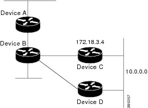
In the following example, packets for network 10.0.0.0 from Device B (where the static route is installed) will be routed
through 172.18.3.4 if a route with an administrative distance less than 110 is not available. The figure below illustrates
this example. The route learned by a protocol with an administrative distance of less than 110 might cause Device B to send
traffic destined for network 10.0.0.0 via the alternate path through Device D.
Device(config)# ip route 10.0.0.0 255.0.0.0 172.18.3.4 110
Example: IP Default Gateway as a Static IP Next Hop When IP Routing Is Disabled
The following example shows how to configure IP address 172.16.5.4 as the default route when IP routing is disabled:
Device> enable
Device# configure terminal
Device(conf)# no ip routing
Device(conf)# ip default-gateway 172.16.15.4
Examples: Administrative Distances
In the following example, the
router eigrp global configuration command configures Enhanced Interior Gateway Routing Protocol (EIGRP) routing in autonomous system 1.
The
network command configuration specifies EIGRP routing on networks 192.168.7.0 and 172.16.0.0. The first
distance router configuration command sets the default administrative distance to 255, which instructs the device to ignore all routing
updates from devices for which an explicit distance has not been set. The second
distance command sets the administrative distance to 80 for internal EIGRP routes and to 100 for external EIGRP routes. The third
distance command sets the administrative distance to 120 for the device with the address 172.16.1.3.
Device(config)# router eigrp 1
Device(config-router)# network 192.168.7.0
Device(config-router)# network 172.16.0.0
Device(config-router)# distance 255
Device(config-router)# distance eigrp 80 100
Device(config-router)# distance 120 172.16.1.3 0.0.0.0
|
Note |
The |
The following example assigns the device with the address 192.168.7.18 an administrative distance of 100 and all other devices
on subnet 192.168.7.0 an administrative distance of 200:
Device(config-router)# distance 100 192.168.7.18 0.0.0.0
Device(config-router)# distance 200 192.168.7.0 0.0.0.255
However, if you reverse the order of these two commands, all devices on subnet 192.168.7.0 are assigned an administrative
distance of 200, including the device at address 192.168.7.18:
Device(config-router)# distance 200 192.168.7.0 0.0.0.255
Device(config-router)# distance 100 192.168.7.18 0.0.0.0
|
Note |
Assigning administrative distances can be used to solve unique problems. However, administrative distances should be applied |
In the following example, the distance value for IP routes learned is 90. Preference is given to these IP routes rather than
routes with the default administrative distance value of 110.
Device(config)# router isis
Device(config-router)# distance 90 ip
Example: Static Routing Redistribution
In the example that follows, three static routes are specified, two of which are to be advertised. The static routes are
created by specifying the
redistribute static router configuration command and then specifying an access list that allows only those two networks to be passed to the Enhanced
Interior Gateway Routing Protocol (EIGRP) process. Any redistributed static routes should be sourced by a single device to
minimize the likelihood of creating a routing loop.
Device(config)# ip route 192.168.2.0 255.255.255.0 192.168.7.65
Device(config)# ip route 192.168.5.0 255.255.255.0 192.168.7.65
Device(config)# ip route 10.10.10.0 255.255.255.0 10.20.1.2
Device(config)# !
Device(config)# access-list 3 permit 192.168.2.0 0.0.255.255
Device(config)# access-list 3 permit 192.168.5.0 0.0.255.255
Device(config)# access-list 3 permit 10.10.10.0 0.0.0.255
Device(config)# !
Device(config)# router eigrp 1
Device(config-router)# network 192.168.0.0
Device(config-router)# network 10.10.10.0
Device(config-router)# redistribute static metric 10000 100 255 1 1500
Device(config-router)# distribute-list 3 out static
Examples: EIGRP Redistribution
Each Enhanced Interior Gateway Routing Protocol (EIGRP) routing process provides routing information to only one autonomous
system. The Cisco software must run a separate EIGRP process and maintain a separate routing database for each autonomous
system that it services. However, you can transfer routing information between these routing databases.
In the following configuration, network 10.0.0.0 is configured under EIGRP autonomous system 1 and network 192.168.7.0 is
configured under EIGRP autonomous system 101:
Device(config)# router eigrp 1
Device(config-router)# network 10.0.0.0
Device(config-router)# exit
Device(config)# router eigrp 101
Device(config-router)# network 192.168.7.0
In the following example, routes from the 192.168.7.0 network are redistributed into autonomous system 1 (without passing
any other routing information from autonomous system 101):
Device(config)# access-list 3 permit 192.168.7.0
Device(config)# !
Device(config)# route-map 101-to-1 permit 10
Device(config-route-map)# match ip address 3
Device(config-route-map)# set metric 10000 100 1 255 1500
Device(config-route-map)# exit
Device(config)# router eigrp 1
Device(config-router)# redistribute eigrp 101 route-map 101-to-1
Device(config-router)#!
The following example is an alternative way to redistribute routes from the 192.168.7.0 network into autonomous system 1.
Unlike the previous configuration, this method does not allow you to set the metric for redistributed routes.
Device(config)# access-list 3 permit 192.168.7.0
Device(config)# !
Device(config)# router eigrp 1
Device(config-router)# redistribute eigrp 101
Device(config-router)# distribute-list 3 out eigrp 101
Device(config-router)# !
Example: Mutual Redistribution Between EIGRP and RIP
Consider a WAN at a university that uses the Routing Information Protocol (RIP) as an interior routing protocol. Assume that
the university wants to connect its WAN to regional network 172.16.0.0, which uses the Enhanced Interior Gateway Routing Protocol
(EIGRP) as the routing protocol. The goal in this case is to advertise the networks in the university network to devices in
the regional network.
Mutual redistribution is configured between EIGRP and RIP in the following example:
Device(config)# access-list 10 permit 172.16.0.0
Device(config)# !
Device(config)# router eigrp 1
Device(config-router)# network 172.16.0.0
Device(config-router)# redistribute rip metric 10000 100 255 1 1500
Device(config-router)# default-metric 10
Device(config-router)# distribute-list 10 out rip
Device(config-router)# exit
Device(config)# router rip
Device(config-router)# redistribute eigrp 1
Device(config-router)# !
In this example, an EIGRP routing process is started. The
network router configuration command specifies that network 172.16.0.0 (the regional network) is to send and receive EIGRP routing
information. The
redistribute router configuration command specifies that RIP-derived routing information be advertised in routing updates. The
default-metric router configuration command assigns an EIGRP metric to all RIP-derived routes. The
distribute-list router configuration command instructs the Cisco software to use access list 10 (not defined in this example) to limit the
entries in each outgoing update. The access list prevents unauthorized advertising of university routes to the regional network.
Example: Mutual Redistribution Between EIGRP and BGP
In the following example, mutual redistribution is configured between the Enhanced Interior Gateway Routing Protocol (EIGRP)
and the Border Gateway Protocol (BGP).
Routes from EIGRP routing process 101 are injected into BGP autonomous system 50000. A filter is configured to ensure that
the correct routes are advertised, in this case, three networks. Routes from BGP autonomous system 50000 are injected into
EIGRP routing process 101. The same filter is used.
Device(config)# ! All networks that should be advertised from R1 are controlled with ACLs:
Device(config)# access-list 1 permit 172.18.0.0 0.0.255.255
Device(config)# access-list 1 permit 172.16.0.0 0.0.255.255
Device(config)# access-list 1 permit 172.25.0.0 0.0.255.255
Device(config)# ! Configuration for router R1:
Device(config)# router bgp 50000
Device(config-router)# network 172.18.0.0
Device(config-router)# network 172.16.0.0
Device(config-router)# neighbor 192.168.10.1 remote-as 2
Device(config-router)# neighbor 192.168.10.15 remote-as 1
Device(config-router)# neighbor 192.168.10.24 remote-as 3
Device(config-router)# redistribute eigrp 101
Device(config-router)# distribute-list 1 out eigrp 101
Device(config-router)# exit
Device(config)# router eigrp 101
Device(config-router)# network 172.25.0.0
Device(config-router)# redistribute bgp 50000
Device(config-router)# distribute-list 1 out bgp 50000
Device(config-router)# ! |
Caution |
BGP should be redistributed into an Interior Gateway Protocol (IGP) when there are no other suitable options. Redistribution |
Examples: OSPF Routing and Route Redistribution
OSPF typically requires coordination among many internal devices, area border routers (ABRs), and Autonomous System Boundary
Routers (ASBRs). At a minimum, OSPF-based devices can be configured with all default parameter values, with no authentication,
and with interfaces assigned to areas.
This section provides the following configuration examples:
-
The first example shows simple configurations illustrating basic OSPF commands.
-
The second example shows configurations for an internal device, ABR, and ASBR within a single, arbitrarily assigned OSPF
autonomous system. -
The third example illustrates a more complex configuration and the application of various tools available for controlling
OSPF-based routing environments.
Examples: Basic OSPF Configuration
The following example illustrates a simple OSPF configuration that enables OSPF routing process 1, attaches Gigabit Ethernet
interface 0/0/0 to area 0.0.0.0, and redistributes RIP into OSPF and OSPF into RIP:
Device(config)# interface GigabitEthernet 0/0/0
Device(config-if)# ip address 172.16.1.1 255.255.255.0
Device(config-if)# ip ospf cost 1
Device(config-if)# exit
Device(config)# interface GigabitEthernet 1/0/0
Device(config-if)# ip address 172.17.1.1 255.255.255.0
Device(config-if)# exit
Device(config)# router ospf 1
Device(config-router)# network 172.18.0.0 0.0.255.255 area 0.0.0.0
Device(config-router)# redistribute rip metric 1 subnets
Device(config-router)# exit
Device(config)# router rip
Device(config-router)# network 172.17.0.0
Device(config-router)# redistribute ospf 1
Device(config-router)# default-metric 1
Device(config-router)# !
The following example illustrates the assignment of four area IDs to four IP address ranges. In the example, OSPF routing
process 1 is initialized, and four OSPF areas are defined: 10.9.50.0, 2, 3, and 0. Areas 10.9.50.0, 2, and 3 mask specific
address ranges, whereas area 0 enables OSPF for all other networks.
Device(config)# router ospf 1
Device(config-router)# network 172.18.20.0 0.0.0.255 area 10.9.50.0
Device(config-router)# network 172.18.0.0 0.0.255.255 area 2
Device(config-router)# network 172.19.10.0 0.0.0.255 area 3
Device(config-router)# network 0.0.0.0 255.255.255.255 area 0
Device(config-router)# exit
Device(config)# ! GigabitEthernet interface 0/0/0 is in area 10.9.50.0:
Device(config)# interface GigabitEthernet 0/0/0
Device(config-if)# ip address 172.18.20.5 255.255.255.0
Device(config-if)# exit
Device(config)# ! GigabitEthernet interface 1/0/0 is in area 2:
Device(config)# interface GigabitEthernet 1/0/0
Device(config-if)# ip address 172.18.1.5 255.255.255.0
Device(config-if)# exit
Device(config)# ! GigabitEthernet interface 2/0/0 is in area 2:
Device(config)# interface GigabitEthernet 2/0/0
Device(config-if)# ip address 172.18.2.5 255.255.255.0
Device(config-if)# exit
Device(config)# ! GigabitEthernet interface 3/0/0 is in area 3:
Device(config)# interface GigabitEthernet 3/0/0
Device(config-if)# ip address 172.19.10.5 255.255.255.0
Device(config-if)# exit
Device(config)# ! GigabitEthernet interface 4/0/0 is in area 0:
Device(config)# interface GigabitEthernet 4/0/0
Device(config-if)# ip address 172.19.1.1 255.255.255.0
Device(config-if)# exit
Device(config)# ! GigabitEthernet interface 5/0/0 is in area 0:
Device(config)# interface GigabitEthernet 5/0/0
Device(config-if)# ip address 10.1.0.1 255.255.0.0
Device(config-if)# !
Each
network router configuration command is evaluated sequentially, so the specific order of these commands in the configuration is important.
The Cisco software sequentially evaluates the
address/wildcard-mask pair for each interface. See the
IP Routing Protocols Command Reference for more information.
Consider the first
network command. Area ID 10.9.50.0 is configured for the interface on which subnet 172.18.20.0 is located. Assume that a match is
determined for Gigabit Ethernet interface 0/0/0. Gigabit Ethernet interface 0/0/0 is attached to Area 10.9.50.0 only.
The second
network command is evaluated next. For Area 2, the same process is then applied to all interfaces (except Gigabit Ethernet interface
0/0/0). Assume that a match is determined for Gigabit Ethernet interface 1/0/0. OSPF is then enabled for that interface, and
Gigabit Ethernet 1/0/0 is attached to Area 2.
This process of attaching interfaces to OSPF areas continues for all
network commands. Note that the last
network command in this example is a special case. With this command, all available interfaces (not explicitly attached to another
area) are attached to Area 0.
Example: Internal Device ABR and ASBRs Configuration
The figure below provides a general network map that illustrates a sample configuration for several devices within a single
OSPF autonomous system.
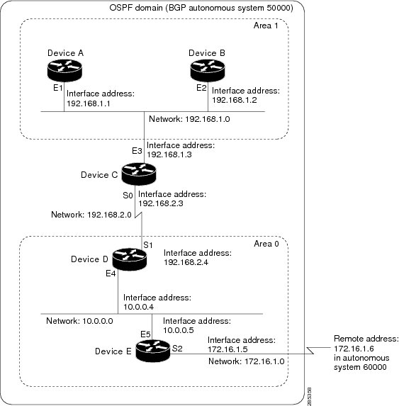
In this configuration, five devices are configured in OSPF autonomous system 1:
-
Device A and Device B are both internal devices within area 1.
-
Device C is an OSPF ABR. Note that for Device C, area 1 is assigned to E3 and Area 0 is assigned to S0.
-
Device D is an internal device in area 0 (backbone area). In this case, both
network router configuration commands specify the same area (area 0, or the backbone area). -
Device E is an OSPF ASBR. Note that the Border Gateway Protocol (BGP) routes are redistributed into OSPF and that these routes
are advertised by OSPF.
|
Note |
Definitions of all areas in an OSPF autonomous system need not be included in the configuration of all devices in the autonomous |
Autonomous system 60000 is connected to the outside world via the BGP link to the external peer at IP address 172.16.1.6.
Following is the sample configuration for the general network map shown in the figure above.
Device A Configuration—Internal Device
Device(config)# interface GigabitEthernet 1/0/0
Device(config-if)# ip address 192.168.1.1 255.255.255.0
Device(config-if)# exit
Device(config)# router ospf 1
Device(config-router)# network 192.168.1.0 0.0.0.255 area 1
Device(config-router)# exit
Device B Configuration—Internal Device
Device(config)# interface GigabitEthernet 2/0/0
Device(config-if)# ip address 192.168.1.2 255.255.255.0
Device(config-if)# exit
Device(config)# router ospf 1
Device(config-router)# network 192.168.1.0 0.0.0.255 area 1
Device(config-router)# exit
Device C Configuration—ABR
Device(config)# interface GigabitEthernet 3/0/0
Device(config-if)# ip address 192.168.1.3 255.255.255.0
Device(config-if)# exit
Device(config)# interface Serial 0/0/0
Device(config-if)# ip address 192.168.2.3 255.255.255.0
Device(config-if)# exit
Device(config)# router ospf 1
Device(config-router)# network 192.168.1.0 0.0.0.255 area 1
Device(config-router)# network 192.168.2.0 0.0.0.255 area 0
Device(config-router)# exit
Device D Configuration—Internal Device
Device(config)# interface GigabitEthernet 4/0/0
Device(config-if)# ip address 10.0.0.4 255.0.0.0
Device(config-if)# exit
Device(config)# interface Serial 1/0/0
Device(config-if)# ip address 192.168.2.4 255.255.255.0
Device(config-if)# exit
Device(config)# router ospf 1
Device(config-router)# network 192.168.2.0 0.0.0.255 area 0
Device(config-router)# network 10.0.0.0 0.255.255.255 area 0
Device(config-router)# exit
Device E Configuration—ASBR
Device(config)# interface GigabitEthernet 5/0/0
Device(config-if)# ip address 10.0.0.5 255.0.0.0
Device(config-if)# exit
Device(config)# interface Serial 2/0/0
Device(config-if)# ip address 172.16.1.5 255.255.255.0
Device(config-if)# exit
Device(config)# router ospf 1
Device(config-router)# network 10.0.0.0 0.255.255.255 area 0
Device(config-router)# redistribute bgp 50000 metric 1 metric-type 1
Device(config-router)# exit
Device(config)# router bgp 50000
Device(config-router)# network 192.168.0.0
Device(config-router)# network 10.0.0.0
Device(config-router)# neighbor 172.16.1.6 remote-as 60000
Example: Complex OSPF Configuration
The following sample configuration accomplishes several tasks in setting up an ABR. These tasks can be split into two general
categories:
-
Basic OSPF configuration
-
Route redistribution
The specific tasks outlined in this configuration are detailed briefly in the following descriptions. The figure below illustrates
the network address ranges and area assignments for the interfaces.
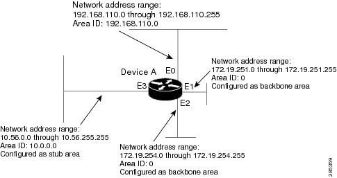
The basic configuration tasks in this example are as follows:
-
Configure address ranges for Gigabit Ethernet interface 0/0/0 through Gigabit Ethernet interface 3/0/0.
-
Enable OSPF on each interface.
-
Set up an OSPF authentication password for each area and network.
-
Assign link-state metrics and other OSPF interface configuration options.
-
Create a stub area with area ID 10.0.0.0. (Note that the
authentication and
stub options of the
area router configuration command are specified with separate
area command entries, but they can be merged into a single
area command.) -
Specify the backbone area (area 0).
Configuration tasks associated with redistribution are as follows:
-
Redistribute the Enhanced Interior Gateway Routing Protocol (EIGRP) and the Routing Information Protocol (RIP) into OSPF
with various options set (including metric-type, metric, tag, and subnet). -
Redistribute EIGRP and OSPF into RIP.
The following is an example OSPF configuration:
Device(config)# interface GigabitEthernet 0/0/0
Device(config-if)# ip address 192.168.110.201 255.255.255.0
Device(config-if)# ip ospf authentication-key abcdefgh
Device(config-if)# ip ospf cost 10
Device(config-if)# exit
Device(config)# interface GigabitEthernet 1/0/0
Device(config-if)# ip address 172.19.251.201 255.255.255.0
Device(config-if)# ip ospf authentication-key ijklmnop
Device(config-if)# ip ospf cost 20
Device(config-if)# ip ospf retransmit-interval 10
Device(config-if)# ip ospf transmit-delay 2
Device(config-if)# ip ospf priority 4
Device(config-if)# exit
Device(config)# interface GigabitEthernet 2/0/0
Device(config-if)# ip address 172.19.254.201 255.255.255.0
Device(config-if)# ip ospf authentication-key abcdefgh
Device(config-if)# ip ospf cost 10
Device(config-if)# exit
Device(config)# interface GigabitEthernet 3/0/0
Device(config-if)# ip address 10.56.0.201 255.255.0.0
Device(config-if)# ip ospf authentication-key ijklmnop
Device(config-if)# ip ospf cost 20
Device(config-if)# ip ospf dead-interval 80
Device(config-if)# exit
In the following configuration, OSPF is on network 172.19.0.0:
Device(config)# router ospf 1
Device(config-router)# network 10.0.0.0 0.255.255.255 area 10.0.0.0
Device(config-router)# network 192.168.110.0 0.0.0.255 area 192.168.110.0
Device(config-router)# network 172.19.0.0 0.0.255.255 area 0
Device(config-router)# area 0 authentication
Device(config-router)# area 10.0.0.0 stub
Device(config-router)# area 10.0.0.0 authentication
Device(config-router)# area 10.0.0.0 default-cost 20
Device(config-router)# area 192.168.110.0 authentication
Device(config-router)# area 10.0.0.0 range 10.0.0.0 255.0.0.0
Device(config-router)# area 192.168.110.0 range 192.168.110.0 255.255.255.0
Device(config-router)# area 0 range 172.19.251.0 255.255.255.0
Device(config-router)# area 0 range 172.19.254.0 255.255.255.0
Device(config-router)# redistribute eigrp 200 metric-type 2 metric 1 tag 200 subnets
Device(config-router)# redistribute rip metric-type 2 metric 1 tag 200
Device(config-router)# exit
In the following configuration, EIGRP autonomous system 1 is on 172.19.0.0:
Device(config)# router eigrp 1
Device(config-router)# network 172.19.0.0
Device(config-router)# exit
Device(config)# ! RIP for 192.168.110.0:
Device(config)# router rip
Device(config-router)# network 192.168.110.0
Device(config-router)# redistribute eigrp 1 metric 1
Device(config-router)# redistribute ospf 201 metric 1
Device(config-router)# exit
Example: Default Metric Values Redistribution
The following example shows a device in autonomous system 1 that is configured to run both the Routing Information Protocol
(RIP) and the Enhanced Interior Gateway Routing Protocol (EIGRP). The example advertises EIGRP-derived routes using RIP and
assigns the EIGRP-derived routes a RIP metric of 10.
Device(config)# router rip
Device(config-router)# redistribute eigrp 1
Device(config-router)# default-metric 10
Device(config-router)# exit
Examples: Redistribution With and Without Route Maps
The examples in this section illustrate the use of redistribution, with and without route maps. Examples from both the IP
and Connectionless Network Service (CLNS) routing protocols are given. The following example redistributes all Open Shortest
Path First (OSPF) routes into the Enhanced Interior Gateway Routing Protocol (EIGRP):
Device(config)# router eigrp 1
Device(config-router)# redistribute ospf 101
Device(config-router)# exit
The following example redistributes Routing Information Protocol (RIP) routes with a hop count equal to 1 into OSPF. These
routes will be redistributed into OSPF as external link state advertisements (LSAs) with a metric of 5, metric a type of type
1, and a tag equal to 1.
Device(config)# router ospf 1
Device(config-router)# redistribute rip route-map rip-to-ospf
Device(config-router)# exit
Device(config)# route-map rip-to-ospf permit
Device(config-route-map)# match metric 1
Device(config-route-map)# set metric 5
Device(config-route-map)# set metric-type type 1
Device(config-route-map)# set tag 1
Device(config-route-map)# exit
The following example redistributes OSPF learned routes with tag 7 as a RIP metric of 15:
Device(config)# router rip
Device(config-router)# redistribute ospf 1 route-map 5
Device(config-router)# exit
Device(config)# route-map 5 permit
Device(config-route-map)# match tag 7
Device(config-route-map)# set metric 15
The following example redistributes OSPF intra-area and interarea routes with next hop devices on serial interface 0/0/0
into the Border Gateway Protocol (BGP) with an INTER_AS metric of 5:
Device(config)# router bgp 50000
Device(config-router)# redistribute ospf 1 route-map 10
Device(config-router)# exit
Device(config)# route-map 10 permit
Device(config-route-map)# match route-type internal
Device(config-route-map)# match interface serial 0/0/0
Device(config-route-map)# set metric 5
The following example redistributes two types of routes into the integrated IS-IS routing table (supporting both IP and CLNS).
The first type is OSPF external IP routes with tag 5; these routes are inserted into Level 2 IS-IS link-state packets (LSPs)
with a metric of 5. The second type is ISO-IGRP derived CLNS prefix routes that match CLNS access list 2000; these routes
will be redistributed into IS-IS as Level 2 LSPs with a metric of 30.
Device(config)# router isis
Device(config-router)# redistribute ospf 1 route-map 2
Device(config-router)# redistribute iso-igrp nsfnet route-map 3

Device(config-router)# exit
Device(config)# route-map 2 permit
Device(config-route-map)# match route-type external
Device(config-route-map)# match tag 5
Device(config-route-map)# set metric 5
Device(config-route-map)# set level level-2
Device(config-route-map)# exit
Device(config)# route-map 3 permit
Device(config-route-map)# match address 2000
Device(config-route-map)# set metric 30
Device(config-route-map)# exit
With the following configuration, OSPF external routes with tags 1, 2, 3, and 5 are redistributed into RIP with metrics of
1, 1, 5, and 5, respectively. The OSPF routes with a tag of 4 are not redistributed.
Device(config)# router rip
Device(config-router)# redistribute ospf 101 route-map 1
Device(config-router)# exit
Device(config)# route-map 1 permit
Device(config-route-map)# match tag 1 2
Device(config-route-map)# set metric 1
Device(config-route-map)# exit
Device(config)# route-map 1 permit
Device(config-route-map)# match tag 3
Device(config-route-map)# set metric 5
Device(config-route-map)# exit
Device(config)# route-map 1 deny
Device(config-route-map)# match tag 4
Device(config-route-map)# exit
Device(config)# route map 1 permit
Device(config-route-map)# match tag 5
Device(config-route-map)# set metric 5
Device(config-route-map)# exit
Given the following configuration, a RIP learned route for network 172.18.0.0 and an ISO-IGRP learned route with prefix 49.0001.0002
will be redistributed into an IS-IS Level 2 LSP with a metric of 5:
Device(config)# router isis
Device(config-router)# redistribute rip route-map 1
Device(config-router)# redistribute iso-igrp remote route-map 1
Device(config-router)# exit
Device(config)# route-map 1 permit
Device(config-route-map)# match ip address 1
Device(config-route-map)# match clns address 2
Device(config-route-map)# set metric 5
Device(config-route-map)# set level level-2
Device(config-route-map)# exit
Device(config)# access-list 1 permit 172.18.0.0 0.0.255.255
Device(config)# clns filter-set 2 permit 49.0001.0002...
The following configuration example illustrates how a route map is referenced by the
default-information router configuration command. This type of reference is called conditional default origination. OSPF will originate the default
route (network 0.0.0.0) with a type 2 metric of 5 if 172.20.0.0 is in the routing table.
Device(config)# route-map ospf-default permit
Device(config-route-map)# match ip address 1
Device(config-route-map)# set metric 5
Device(config-route-map)# set metric-type type-2
Device(config-route-map)# exit
Device(config)# access-list 1 172.20.0.0 0.0.255.255
Device(config)# router ospf 101
Device(config-router)# default-information originate route-map ospf-default
Examples: Key Management
The following example configures a key chain named chain1. In this example, the software always accepts and sends key1 as
a valid key. The key key2 is accepted from 1:30 p.m. to 3:30 p.m. and is sent from 2:00 p.m. to 3:00 p.m. The overlap allows
for migration of keys or discrepancy in the set time of the device. Likewise, the key key3 immediately follows key2, and there
is 30-minutes on each side to handle time-of-day differences.
Device(config)# interface GigabitEthernet 0/0/0
Device(config-if)# ip rip authentication key-chain chain1
Device(config-if)# ip rip authentication mode md5
Device(config-if)# exit
Device(config)# router rip
Device(config-router)# network 172.19.0.0
Device(config-router)# version 2
Device(config-router)# exit
Device(config)# key chain chain1
Device(config-keychain)# key 1
Device(config-keychain-key)# key-string key1
Device(config-keychain-key)# exit
Device(config-keychain)# key 2
Device(config-keychain-key)# key-string key2
Device(config-keychain-key)# accept-lifetime 13:30:00 Jan 25 2005 duration 7200
Device(config-keychain-key)# send-lifetime 14:00:00 Jan 25 2005 duration 3600
Device(config-keychain-key)# exit
Device(config-keychain)# key 3
Device(config-keychain-key)# key-string key3
Device(config-keychain-key)# accept-lifetime 14:30:00 Jan 25 2005 duration 7200
Device(config-keychain-key)# send-lifetime 15:00:00 Jan 25 2005 duration 3600
Device(config-keychain-key)# end
The following example configures a key chain named chain1:
Device(config)# key chain chain1
Device(config-keychain)# key 1
Device(config-keychain-key)# key-string key1
Device(config-keychain-key)# exit
Device(config-keychain)# key 2
Device(config-keychain-key)# key-string key2
Device(config-keychain-key)# accept-lifetime 00:00:00 Dec 5 2004 23:59:59 Dec 5 2005
Device(config-keychain-key)# send-lifetime 06:00:00 Dec 5 2004 18:00:00 Dec 5 2005
Device(config-keychain-key)# exit
Device(config-keychain)# exit
Device(config)# interface GigabitEthernet 0/0/0
Device(config-if)# ip address 172.19.104.75 255.255.255.0 secondary 172.19.232.147 255.255.255.240
Device(config-if)# ip rip authentication key-chain chain1
Device(config-if)# media-type 10BaseT
Device(config-if)# exit
Device(config)# interface GigabitEthernet 1/0/0
Device(config-if)# no ip address
Device(config-if)# shutdown
Device(config-if)# media-type 10BaseT
Device(config-if)# exit
Device(config)# interface Fddi 0
Device(config-if)# ip address 10.1.1.1 255.255.255.0
Device(config-if)# no keepalive
Device(config-if)# exit
Device(config)# interface Fddi 1/0/0
Device(config-if)# ip address 172.16.1.1 255.255.255.0
Device(config-if)# ip rip send version 1
Device(config-if)# ip rip receive version 1
Device(config-if)# no keepalive
Device(config-if)# exit
Device(config)# router rip
Device(config-router)# version 2
Device(config-router)# network 172.19.0.0
Device(config-router)# network 10.0.0.0
Device(config-router)# network 172.16.0.0
Additional References
Related Documents
|
Related |
Document |
|---|---|
|
IP |
|
Technical Assistance
|
Description |
Link |
|---|---|
|
The Cisco |
http://www.cisco.com/cisco/web/support/index.html |
Feature Information for Basic
IP Routing
The following table provides release information about the feature or features described in this module. This table lists
only the software release that introduced support for a given feature in a given software release train. Unless noted otherwise,
subsequent releases of that software release train also support that feature.
Use Cisco Feature Navigator to find information about platform support and Cisco software image support. To access Cisco
Feature Navigator, go to www.cisco.com/go/cfn. An account on Cisco.com is not required.
В прошлой статье мы с вами обсудили процесс маршрутизации между сетями, подключенными к интерфейсами одного единственного маршрутизатора (рекомендую ознакомиться с ней), сегодня же мы разберем, как осуществляется маршрутизация между сетями, подключенными к разным маршрутизаторам, связанным между собой. Пока что мы не будим лезть в дебри протоколов динамической маршрутизации, а разберемся, как пользоваться статической маршрутизацией. В качестве примеров, для демонстрации настройки будим использовать маршрутизаторы фирмы Cisco, доступные в Packet Tracer.
Как мы уже выяснили, если у нас всего один маршрутизатор, то нам достаточно всего лишь сконфигурировать его интерфейсы, и он сразу же будет выполнять маршрутизацию между сетями, подключенными к нему. Немного по иному обстоят дела, если в нашей сети есть несколько маршрутизаторов. Допустим, наша интерсеть сеть будет иметь следующий вид:
 |
| Объединение сетей с помощью маршрутизаторов |
Как мы и обсуждали ранее сети, подключенные к интерфейсам одного маршрутизатора, будут видеть друг друга. Так сети «левого » маршрутизатора 192.168.1.0/24, 172.20.0.0/16 и 192.168.100.0/30 будут видеть друг друга. Аналогично обстоят дела с «правым» маршрутизатором. Но вот как будут обстоять дела с взаимодействием сетей данных маршрутизаторов между собой? Например, компьютеры сети 10.0.0.0/8 не будут доступны из сети 192.168.1.0/24. Данный принцип, для всех сетей, проиллюстрирован на «жестком» рисунке ниже:
 |
| Карта доступности сетей |
Почему же некоторые сети не видят друг друга. Все очень просто, соседние маршрутизаторы не содержат записей о сетях подключенных, только к другому маршрутизатору. Например, маршрутизатор «левый» не знает о существование сети 10.0.0.0/8, подключенной к «правому» маршрутизатору.
Давайте сымитируем данную ситуацию в Cisco Packet Tracer, а заодно поищем пути ее решения. Для начала соберем в Packet Tracer следующую схему (как это сделать смотрите в предыдущей статье):
 |
| Начинаем собирать нашу сеть |
На данной схеме компьютер PC0 имеет IP адрес – 192.168.1.100, PC1 – 172.20.20.100, PC2 – 192.168.2.100, PC3 – 10.10.10.100. Интерфейсы маршрутизатора, к которым подключены компьютеры, имеют такие же адреса, как и сами компьютеры, только в четвертом октете стоит 1. Например, для интерфейса к которому подключен ПК с адресом 192.168.1.100 зададим IP адрес 192.168.1.1. В качестве шлюза по умолчанию у каждого компьютера указан интерфейс маршрутизатора, к которому он подключен. После настройке интерфейсов маршрутизаторов, сохраните их конфигурации, выполнив wr mem. Далее соединим маршрутизаторы между собой. Чтобы это сделать, нам потребуется добавить к маршрутизатору интерфейсную плату. В данном случае добавим к маршрутизатору плату NM-1FE-TX (NM – Network module, 1FE – содержит один порт FastEthernet, TX – поддерживает 10/100MBase-TX).Чтобы это сделать перейдите к окну конфигурации маршрутизатора, выключите его, щелкнув по кнопке питания изображенной на нем.
 |
| Кнопка выключения маршрутизатора в Packet Tracer |
После этого перетяните необходимую интерфейсную плату в разъем маршрутизатора.
 |
| Вставляем интерфейсную плату в маршрутизатор |
После того как карта добавлена, еще раз щелкните по тумблеру маршрутизатора, чтобы включить его. Посмотрите его интерфейсы, должен добавиться еще один – FastEthernet1/0. Повторите аналогичные действия со вторым маршрутизатором. Задайте интерфейсу FastEthernet1/0 «левого» маршрутизатора IP адрес 192.168.100.1 c с маской 255.255.255.252, а «правому маршрутизатору» 192.168.100.2 с аналогичной маской. После этого соедините интерфейсы FastEthernet1/0 этих маршрутизаторов между собой.
 |
| Маршрутизатору, соединенные между собой |
Проверим доступность компьютеров одной сети из других. Если все сделано верно, то картина доступности должна соответствовать второму рисунку данной статьи. Если вы внимательно посмотрите на данный рисунок, то заметите что на данном рисунке не все стрелки двунаправленные. С двунаправленными стрелками все понятно, если вы будите пинговать в данном направлении, то компьютеры будут отвечать вам на ваши ICMP запросы (так как происходит маршрутизация в пределах одного маршрутизатора). Намного интереснее обстоит дело с однонаправленными зелеными стрелками. Хотя пинги в данном направлении не проходят, на самом деле ICMP пакеты доходят до места назначения, но вот вернуться обратно уже не могут. Рассмотрим как это происходит на конкретном примере. Допустим, с компьютера с IP адресом 172.20.20.100 вы пытаетесь пропинговать интерфейс с IP адресом 192.168.100.2, «правого» маршрутизатора. Картина будет выглядеть следующим образом:
 |
| Интерфейс «правого» маршрутизатора не отвечает |
Попробуем отследить путь ICMP пакетов. Для этого включим дебаги (режим отладки определенных параметров) на маршрутизаторах, через которые предположительно должны пройти ICMP пакеты. Выполним команду debug ip packet, на обоих маршрутизаторах. После чего опять попытаемся пропинговать с адреса 172.20.20.100 адрес 192.168.100.2. Посмотрим, что появилось на «левом маршрутизаторе»:
IP: tableid=0, s=172.20.20.100 (FastEthernet0/1), d=192.168.100.2 (FastEthernet1/0), routed via RIB
IP: s=172.20.20.100 (FastEthernet0/1), d=192.168.100.2 (FastEthernet1/0), g=192.168.100.2, len 128, forward
Первая строка говорит о том, что на маршрутизатор прибыл пакет с адреса 172.20.20.100, направляемый на адрес 192.168.100.2. Во второй строчке говорится о том, что данный пакеты был передан дальше, ключевое слово здесь «forward».
Теперь посмотри, что творится в это же время на «правом» маршрутизаторе:
IP: tableid=0, s=172.20.20.100 (FastEthernet1/0), d=192.168.100.2 (FastEthernet1/0), routed via RIB
IP: s=172.20.20.100 (FastEthernet1/0), d=192.168.100.2 (FastEthernet1/0), len 128, rcvd 3
IP: s=192.168.100.2 (local), d=172.20.20.100 len 128, unroutable
Как видно из первых двух строчек, наш ICMP пакет все таки дошел до «правого» маршрутизатора. А что должен сделать интерфейс, на который направлялся ping? Правильно, ответить на него послав ICMP пакеты в обратном направлении с адреса 192.168.100.2 на 172.20.20.100. Вот тут то и начинаются проблемы. «Правый» маршрутизатор не имеет в своей таблице маршрутизации информации о сети 172.20.20.0/16. Шлюз по умолчанию мы еще не прописывали, поэтому маршрутизатор просто не может отослать ответы, в результате чего появляется третья строка дебага, ключевое слово в которой «unroutable».
После того как мы разобрались с тем, как в нашей сети, в данный момент, ходят пакеты. Отключим дебаги (no debug ip packet – отключает включенный ранее дебаг, show debugging – позволяет посмотреть включенные дебаги), и перейдем к настройке маршрутизации.
В нашей маленькой сети, самым простым способом настроить маршрутизацию, является добавление маршрута по умолчанию. Для того чтобы это сделать выполните на «левом» маршрутизаторе в режиме конфигурирования следующую команду:
ip route 0.0.0.0 0.0.0.0 192.168.100.2
На «правом» маршрутизаторе:
ip route 0.0.0.0 0.0.0.0 192.168.100.1
В следующих командах первые 4 цифры обозначают IP адрес сети назначения, следующие 4 цифры обозначают её маску, а последние 4 цифры – это IP адрес интерфейса, на который необходимо передать пакеты, чтобы попасть в данную сеть. Если мы указываем в качестве адреса сети 0.0.0.0 с маской 0.0.0.0, то данный маршрут становится маршрутом по умолчанию, и все пакеты, адреса назначения которых, прямо не указаны в таблице маршрутизации будут отправлены на адрес, указанный в нем.
Посмотрим как это выглядит на конкретном примере. Допустим, мы хотим пропинговать с компьютера с адресом 192.168.1.100 компьютер с IP адресом 10.10.10.100. В качестве шлюза по умолчанию на компьютере с адресом 192.168.1.100 установлен адрес интерфейса маршрутизатора 192.168.1.1. Сначала компьютер будет искать в свой таблице маршрутизации (да у обычного компьютера она тоже есть) непосредственно адрес 10.10.10.100, после того как он его не найдет, он начнет искать в таблице маршрутизации маршрут к сети 10.0.0.0/8. После того, как данный маршрут так же не будет обнаружен. ICMP пакеты будут отправлены на адрес по умолчанию, то есть на интерфейс маршрутизатора с адресом 192.168.1.1. Получив пакет, маршрутизатор просмотрит адрес его назначения – 10.10.10.100 и также попытается обнаружить его в свой таблице маршрутизации. Когда это не увенчается успехом, маршрутизатор попробует найти в свой таблице маршрутизации маршрут к сети 10.0.0.0/8. Когда он не обнаружит и его, пакет будет отправлен используя, только что заданный нами, маршрут по умолчанию. И ICMP пакет будет передан на интерфейс, с адресом 192.168.100.2, «правого» маршрутизатора. Правый маршрутизатор попробует обнаружить в свой таблице маршрутизации маршрут к адресу 10.10.10.100. Когда это не увенчается успехом, «правый» маршрутизатор будет искать маршрут к сети 10.0.0.0/8. Информация о данной сети содержится в таблице маршрутизации, и маршрутизатор знает, что для того чтобы попасть в данную сеть необходимо отправить пакеты на интерфейс FastEthernet0/1, непосредственно к которому подключена данная сеть. Так как в нашем примере вся сеть 10.0.0.0/8, представляет из себя всего 1 компьютер, то пакеты сразу же попадают в место назначения, компьютер с IP адресом 10.10.10.100. При отсылке ответных ICMP пакетов, все происходит аналогичным образом, только адресом назначения уже будет являться 192.168.1.100/24.
К сожалению далеко не всегда можно обойтись указанием только маршрутов по умолчанию. В более сложных сетевых конфигурациях может потребоваться прописывать маршрут для каждой из сетей в отдельности. Давайте сразу рассмотрим как же это делается. Для этого, сначала удалим из таблицы маршрутизации все статически добавленные маршруты, используя команду no ip route xxxx(адрес сети) yyyy(маска) zzzz(адрес интерфейса). В конечном итоге таблицы маршрутизации должны содержать только информацию о непосредственно подключенных к ним сетях. Для «левого» маршрутизатора таблица будет примерно такой:
 |
| Содержимое таблицы маршрутизации |
Теперь нам необходимо добавить к каждому из маршрутизаторов маршруты к двум сетям, которые ему неизвестны (к сетям, подключенным к соседнему маршрутизатору). На «левом» маршрутизаторе выполним:
ip route 192.168.2.0 255.255.255.0 192.168.100.2
ip route 10.0.0.0 255.0.0.0 192.168.100.2
На правом маршрутизаторе выполним:
ip route 192.168.1.0 255.255.255.0 192.168.100.1
ip route 172.20.0.0 255.255.0.0 192.168.100.1
Если все сделано верно, то ваши сети должны будут взаимодействовать согласно рисунку:
 |
| Карта сети |
Как вы видите нам пришлось добавить довольно много маршрутной информации, даже в такой простой сетевой конфигурации. А представьте сколько их придется прописывать, если у вас сеть имеющая десятки маршрутизаторов… Это будет адский труд. Поэтому в больших сетях обычно используют динамическую маршрутизацию, которая кроме облегчения составления таблиц маршрутизации имеет и другие плюсы. О динамической маршрутизации, мы поговорим с вами в следующих статьях.
In this article, we will communicate with computers in two different segments with Static Routing.

How to Configure Static Routing on Cisco Router
There are two types of routing. These;
1. Static Routing
2. Dynamic Routing
In this article, after explaining what Static Routing is and how it works, we will configure routing in a small network environment.
If the network environment consists of several Routers, it is recommended that you use static routes for routing. This is because when routers are configured with Dynamic Routing, they run slower in performance. However, in a small network environment, we can manually add routes to make the routers more efficient.
You need to manually configure this type of routing. However, in a growing network, it would be difficult to do this, so you can use one of the dynamic routing types.
Now, to add a static route to your routers with Cisco Packet Tracer, follow the steps below.
Step 1
Open the simulator program and configure the TCP/IP settings of the computers after creating the network topology as shown in the image below.

Step 2
To configure the GigabitEthernet and Serial interfaces of the Cisco Router, open the CLI prompt and execute the following commands.
Router#conf t
Enter configuration commands, one per line. End with CNTL/Z.
Router(config)#hostname R1
R1(config)#
R1(config)#interface gigabitethernet 0/0
R1(config-if)#ip address 192.168.5.1 255.255.255.0
R1(config-if)#no shutdown
R1(config-if)#
%LINK-5-CHANGED: Interface GigabitEthernet0/0, changed state to up
%LINEPROTO-5-UPDOWN: Line protocol on Interface GigabitEthernet0/0, changed state to up
R1(config-if)#exit
R1(config)#
R1(config)#interface serial0/1/0
R1(config-if)#ip address 10.1.1.1 255.255.255.0
R1(config-if)#no shutdown
%LINK-5-CHANGED: Interface Serial0/1/0, changed state to down
R1(config-if)#end
R1#
%SYS-5-CONFIG_I: Configured from console by console
R1#

Step 3
In the same way, configure the GigabitEthernet and Serial interfaces of the R2 router with the following commands.
Router#conf t
Enter configuration commands, one per line. End with CNTL/Z.
Router(config)#hostname R2
R2(config)#
R2(config)#interface gigabitethernet 0/0
R2(config-if)#ip address 192.168.10.1 255.255.255.0
R2(config-if)#no shutdown
R2(config-if)#
%LINK-5-CHANGED: Interface GigabitEthernet0/0, changed state to up
%LINEPROTO-5-UPDOWN: Line protocol on Interface GigabitEthernet0/0, changed state to up
R2(config-if)#exit
R2(config)#
R2(config)#interface serial 0/1/0
R2(config-if)#ip address 10.1.1.2 255.255.255.0
R2(config-if)#no shutdown
R2(config-if)#
%LINK-5-CHANGED: Interface Serial0/1/0, changed state to up
R2(config-if)#end
R2#

Step 4
Before adding a static route to the routers, ping the default gateway from PC0 and the Serial interface of R1 to test the network connection.
Pinging will be successful as follows.

Step 5
Also, test the connection by pinging the default gateway via PC1 and the Serial interface of the R2 to which it is connected.

Step 6
When you ping the PC0 to the Serial interface of Cisco Router R2 and the computer on its 192.168.5.0/24 network, it will fail as shown in the image below.

Step 7
Also, ping R11’s interfaces from PC1 and check the result.

Step 8
Pinging between clients in two segments failed because no routing enabled in the network environment. If you ping the Router from the Router according to this network design, you will see that the result is successful.
For example, ping from R1 to R2 would be successful as follows;

Step 9
Pinging from R2 to R1 will also be successful.

Step 10
Now add a static route to the Routers so that PC0 can communicate with PC1. To add a static route to R1, execute the command ip route 192.168.10.0 255.255.255.0 10.1.1.2.
R1#conf t
Enter configuration commands, one per line. End with CNTL/Z.
R1(config)#ip route 192.168.10.0 255.255.255.0 10.1.1.2
R1(config)#exit
R1#
#ip route 192.168.10.0 255.255.255.0 10.1.1.2")
After enabling Static routing on R1, execute the show ip route command and check whether the output contains line S 192.168.10.0/24 via 10.1.1.2.
R1#show ip route
Codes: L - local, C - connected, S - static, R - RIP, M - mobile, B - BGP
D - EIGRP, EX - EIGRP external, O - OSPF, IA - OSPF inter area
N1 - OSPF NSSA external type 1, N2 - OSPF NSSA external type 2
E1 - OSPF external type 1, E2 - OSPF external type 2, E - EGP
i - IS-IS, L1 - IS-IS level-1, L2 - IS-IS level-2, ia - IS-IS inter area
* - candidate default, U - per-user static route, o - ODR
P - periodic downloaded static route

Gateway of last resort is not set

10.0.0.0/8 is variably subnetted, 2 subnets, 2 masks
C 10.1.1.0/24 is directly connected, Serial0/1/0
L 10.1.1.1/32 is directly connected, Serial0/1/0
192.168.5.0/24 is variably subnetted, 2 subnets, 2 masks
C 192.168.5.0/24 is directly connected, GigabitEthernet0/0
L 192.168.5.1/32 is directly connected, GigabitEthernet0/0
S 192.168.10.0/24  via 10.1.1.2
R1#
S 192.168.10.0/24 via 10.1.1.2 ⇒ This line indicates that PC0 will reach the network environment 192.168.10.0/24 via the IP address 10.1.1.2.
Step 11
To add a static route to R2, use the following command:
R2#conf t
Enter configuration commands, one per line. End with CNTL/Z.
R2(config)#
R2(config)#ip route 192.168.5.0 255.255.255.0 10.1.1.1
R2(config)#
R2(config)#exit
R2#
#ip route 192.168.5.0 255.255.255.0 10.1.1.1")
Show ip route command output in R2;
R2#show ip route
Codes: L - local, C - connected, S - static, R - RIP, M - mobile, B - BGP
D - EIGRP, EX - EIGRP external, O - OSPF, IA - OSPF inter area
N1 - OSPF NSSA external type 1, N2 - OSPF NSSA external type 2
E1 - OSPF external type 1, E2 - OSPF external type 2, E - EGP
i - IS-IS, L1 - IS-IS level-1, L2 - IS-IS level-2, ia - IS-IS inter area
* - candidate default, U - per-user static route, o - ODR
P - periodic downloaded static route

Gateway of last resort is not set

10.0.0.0/8 is variably subnetted, 2 subnets, 2 masks
C 10.1.1.0/24 is directly connected, Serial0/1/0
L 10.1.1.2/32 is directly connected, Serial0/1/0
S 192.168.5.0/24  via 10.1.1.1
192.168.10.0/24 is variably subnetted, 2 subnets, 2 masks
C 192.168.10.0/24 is directly connected, GigabitEthernet0/0
L 192.168.10.1/32 is directly connected, GigabitEthernet0/0
R2#
S 192.168.5.0/24 via 10.1.1.1 ⇒ This line indicates that PC1 will access the network environment 192.168.5.0/24 via IP address 10.1.1.1.
Step 12
After configuring Static Routing on routers, test the connection by pinging PC0 to PC1. Clients in two different locations will now be able to communicate successfully with each other.

Step 13
Likewise, when pinging from PC1 to PC0, ping will be successful as follows.

Show Commands
R1#show running-config
Building configuration...

Current configuration : 813 bytes
!
version 15.1
no service timestamps log datetime msec
no service timestamps debug datetime msec
no service password-encryption
!
hostname R1
!
no ip cef
no ipv6 cef
!
license udi pid CISCO1941/K9 sn FTX152494BG
!
spanning-tree mode pvst
!
interface GigabitEthernet0/0
ip address 192.168.5.1 255.255.255.0
duplex auto
speed auto
!
interface GigabitEthernet0/1
no ip address
duplex auto
speed auto
shutdown
!
interface Serial0/1/0
ip address 10.1.1.1 255.255.255.0
clock rate 2000000
!
interface Serial0/1/1
no ip address
clock rate 2000000
shutdown
!
interface Vlan1
no ip address
shutdown
!
ip classless
ip route 192.168.10.0 255.255.255.0 10.1.1.2
!
ip flow-export version 9
!
line con 0
!
line aux 0
!
line vty 0 4
login
!
end
R1#
R2#show running-config
Building configuration...

Current configuration : 793 bytes
!
version 15.1
no service timestamps log datetime msec
no service timestamps debug datetime msec
no service password-encryption
!
hostname R2
!
no ip cef
no ipv6 cef
!
license udi pid CISCO1941/K9 sn FTX1524GA8Z
!
spanning-tree mode pvst
!
interface GigabitEthernet0/0
ip address 192.168.10.1 255.255.255.0
duplex auto
speed auto
!
interface GigabitEthernet0/1
no ip address
duplex auto
speed auto
shutdown
!
interface Serial0/1/0
ip address 10.1.1.2 255.255.255.0
!
interface Serial0/1/1
no ip address
clock rate 2000000
shutdown
!
interface Vlan1
no ip address
shutdown
!
ip classless
ip route 192.168.5.0 255.255.255.0 10.1.1.1
!
ip flow-export version 9
!
line con 0
!
line aux 0
!
line vty 0 4
login
!
!
end
R2#
Video
You can watch the video below to enable Static Routing on Packet Tracer and also subscribe to our YouTube channel to support us!
Final Word
In this article, we have added static routes to two routers using the Cisco simulator software and communicated computers in two segments. Thanks for following us!
Related Articles
♦ Creating a Network
♦ Cisco DHCP
♦ Cisco Telnet
♦ Cisco SSH
♦ Cisco Static NAT
In this section, we will be going to discuss how to configure Static Routing between two routers using Cisco Packet Tracer. You can also use other Simulation software like Boson, GNS, etc. This software is freely available on their respective official sites. You can download them and install them on your system.
However, It will be better if you can afford two live routers, but economically it is not feasible. Simulation software works well and accepts almost all the CLI commands. Hence, it is much better and economic for the hands-on practice of the Cisco router Commands.
Configuration of Static Routing
Static routing between two routers is configured manually by the network administrator. It is considered to be more reliable and secure routing than dynamic routing. But, static routing is more effective in smaller networks. As the network size increases, it is difficult to manage every router manually.
While configuring the static routing, we do not have to make the entry of directly connected networks, since they are locally connected with the router ports. We have to make the entry of indirectly connected networks via next-hop router interface IP or the exit interface.
The CLI command for configuring static routing is:
For example:
Router(config)#ip route 192.168.1.0 255.255.255.0 10.0.0.2
Here, we are taking two routers for static routing configuration.
Let us look at the network scenario.
 How to Set up Connectivity
 How to Set up Connectivity
- Take two Cisco Routers Model 2911, two Ethernet Switches, and four generic PCs.
- Connect them using the appropriate cables.
- Use RJ 45 copper straight cable for connecting router LAN interface ( Gigabit Ethernet Port) with Switch Fast Ethernet port and switch to PC as shown in the diagram.
- Use Serial Cable to connect the serial interface of the two routers for point to point connection.
- The serial interface is not integrated with the router, hence it has to be fitted externally. Insert the serial card ( here we are taking HWIT-2T )to the appropriate serial card slot. Please be sure that the router is off while inserting the card to the slot.
- While configuring serial interface between two routers, please keep in mind that one end will be the DCE (Data Communication Equipment)and the other end will be DTE (Data Terminal Equipment).
- We have to assign a clock rate or the bandwidth to the DCE end. The clock rate is written in bit per sec. Suppose, we have to assign channel bandwidth of 1Mbps, the clock rate is set as 1000000.
Distribution of IP addresses across the respective Interfaces
Follow the table below and configure the following IP addresses to the respective ports of the two routers and the PCs.
| Srl No | Devices | IP address | Subnet Mask | Default gateway | Interfaces |
| 1 | Router 1 | 192.168.1.1 | 255.255.255.0 | Gigabit Ethernet 0/0 |
| 2 | Router 1 | 10.0.0.1 | 255.0.0.0 | Serial 0/0/0 |
| 3 | Router 2 | 192.168.2.1 | 255.255.255.0 | Gigabit Ethernet 0/0 |
| 4 | Router 2 | 10.0.0.2 | 255.0.0.0 | Serial 0/0/0 |
| 5 | PC 0 | 192.168.1.5 | 255.255.255.0 | 192.168.1.1 | Ethernet |
| 6 | PC 1 | 192.168.1.10 | 255.255.255.0 | 192.168.1.1 | Ethernet |
| 7 | PC 2 | 192.168.2.5 | 255.255.255.0 | 192.168.2.1 | Ethernet |
| 8 | PC 2 | 192.168.2.10 | 255.255.255.0 | 192.168.2.1 | Ethernet |
Router 1 Configuration
When the router enters into the initial set up mode after the booting process. Type NO and hit the Enter key to go to the User Exec Mode.
STEP 1.1: Configure IP Address for Gigabit Ethernet 0/0 interface
Would you like to enter the initial configuration dialog? [yes/no]: no
Press RETURN to get started!
Router1>enable
Router1#config t
Router1(config)#interface Gigabit Ethernet 0/0
Router1(config-if)#ip address 192.168.1.1 255.255.255.0
Router1(config-if)#no shutdown
Router1(config-if)#exit
Router1(config)#
STEP 1.2: Configure the IP Address for the Serial 0/0/0 interface.
Router1(config-if)#ip address 10.0.0.1 255.0.0.0
Router1(config-if)#clock rate 1000000
Router1(config-if)#no shutdown
Router1(config-if)#exit
STEP 1.3: Configure Static Routing for Router 1 and save the configuration.
Router1(config)#exit
Router#write
Building configuration…
[OK]
Router 2 Configuration
Now, configure the router 2 similarly as router 1, but with different IP addresses.
STEP 2.1: Configure IP Address for Gigabit Ethernet 0/0 interface
Would you like to enter the initial configuration dialog? [yes/no]: no
Press RETURN to get started!
Router2>enable
Router2#config t
Router2(config)#interface Gigabit Ethernet 0/0
Router2(config-if)#ip address 192.168.2.1 255.255.255.0
Router2(config-if)#no shutdown
Router2(config-if)#exit
Router2(config)#
STEP 2.2: Configure the IP Address for the Serial 0/0/0 interface.
Router2(config-if)#ip address 10.0.0.2 255.0.0.0
Router2(config-if)#no shutdown
Router2(config-if)#exit
STEP 2.3: Configure Static Routing for Router 1 and save the configuration.
Router2(config)#exit
Router2#write
Building configuration…
[OK]
Check the configuration by executing the PING command from the PC of one network to another network. If the ping is successful, that means static routing is configured between two routers is configured successfully.
| ← Prev | Next → | |
| What is IP Routing and it’s Types | What is Dynamic Routing and it’s Types |
Administrative distance, Cost, Distance vector protocol, Hop, Link state protocol, Routing, Routing protocol, What is dynamic routing, What is static routing
В прошлой шпаргалке мы выполнили базовую настройку роутера и назначили IP-адреса интерфейсам роутера («Базовая настройка роутера Cisco»).
Однако (надеюсь Вы помните из готового примера), у нас еще нет возможности отправить удачный пинг в другую сеть (из PC1 к PC3).
Для этого мы и настроим статическую маршрутизацию, которая будет объяснять роутеру где находится другая сеть.
// Так я буду обозначать комментарии.
-
Устанавливаем консольное соединение через гипертерминал со следующими настройками:
- Скорость: 9600; Биты данных: 8; Четность: Нет; Стоповые биты: 1; Управление потоком: Нет;
- //при входе на роутер вводим пароль — cisco
- R1>enable//Входим в привилегированный режим.
- //вводим пароль — class
- R1#
- R1#configure terminal//заходим в режим глобальной конфигурации
- R1(config)#ip route 172.16.0.0 255.255.255.128 Serial0/0/0//это команда для ввода статического маршрута/ Объясняю вкратце: ip route — это команда, говорящая роутеру, что сейчас будет введен статический маршрут; 172.16.0.0 — это удаленная и неизвестная роутеру сеть; 255.255.255.128 — это маска удаленной сети; serial0/0/0 — это на какой интерфейс слать пакеты, предназначающиеся для той, удаленной сети.
- //помимо вышеназванного способа можно воспользоваться другими командами:
ip route 172.16.0.0 255.255.255.128 192.168.0.194 — в этом случае все тоже самое, только вместо указания интерфейса на какой слать пакеты, указан IP-адрес подключенного интерфейса следующего роутера.
ip route 172.16.0.0 255.255.0.0 Serial0/0/0 — здесь мы увеличили диапазон адресов маской. Теперь на интерфейс уйдут не только пакеты с адресами 172.16.0.1-126, но и 172.16.255.254. Это называется суммированием маршрутов, и заслуживает другой статьи.
ip route 0.0.0.0 0.0.0.0 Serial0/0/0 — а это называется маршрут по умолчанию, т.е. всё, что не предназначается для известных роутеру сетей уйдёт на интерфейс Serial0/0/0.
- R1(config-line)#end//выходим в привилегированный режим EXEC Mode
- R1#show running-config//Проверяем введенные данные.
- R1#copy running-config startup-config//Сохраняем произведенную настройку в энерго-независимую память.
Скачать выполненное задание настройки роутера
Предлагаю скачать файл с выполненным заданием для программы эмулятора PacketTracer, открыть его и посмотреть на реализацию. Роутер R2 тоже настроен со статической маршрутизацией, следовательно теперь всё удачно пингуется.
Настройка роутера копированием конфигурации
-
Для автоматической базовой настройки (всё, что выше) маршрутизатора выполните следующие действия:
- 1. Скопируйте текст ниже в буфер обмена: выделите всё, кликните правой кнопкой по выделенному и выберите «Копировать».
- 2. При необходимости очистите роутер от всех настроек и перезагрузите его.
- 3. Войдите в режим глобальной конфигурации и вызовите меню Гипер Терминала «Правка», а в нём «Передать главному компьютеру».
- 4. Обязательно проверьте настройки с помощью команды
show running-config - 5. При необходимости включите интерфейсы командой no shutdown из режима каждого интерфейса