Introduction
Internet Protocol Security (IPsec) is a set of protocols defined by the Internet Engineering Task Force (IETF) to secure packet exchange over unprotected IP/IPv6 networks such as the Internet.
IPsec protocol suite can be divided into the following groups:
- Internet Key Exchange (IKE) protocols. Dynamically generates and distributes cryptographic keys for AH and ESP.
- Authentication Header (AH) RFC 4302
- Encapsulating Security Payload (ESP) RFC 4303
Internet Key Exchange Protocol (IKE)
The Internet Key Exchange (IKE) is a protocol that provides authenticated keying material for the Internet Security Association and Key Management Protocol (ISAKMP) framework. There are other key exchange schemes that work with ISAKMP, but IKE is the most widely used one. Together they provide means for authentication of hosts and automatic management of security associations (SA).
Most of the time IKE daemon is doing nothing. There are two possible situations when it is activated:
There is some traffic caught by a policy rule which needs to become encrypted or authenticated, but the policy doesn’t have any SAs. The policy notifies the IKE daemon about that, and the IKE daemon initiates a connection to a remote host. IKE daemon responds to remote connection. In both cases, peers establish a connection and execute 2 phases:
- Phase 1 — The peers agree upon algorithms they will use in the following IKE messages and authenticate. The keying material used to derive keys for all SAs and to protect following ISAKMP exchanges between hosts is generated also. This phase should match the following settings:
- authentication method
- DH group
- encryption algorithm
- exchange mode
- hash algorithm
- NAT-T
- DPD and lifetime (optional)
- Phase 2 — The peers establish one or more SAs that will be used by IPsec to encrypt data. All SAs established by the IKE daemon will have lifetime values (either limiting time, after which SA will become invalid, or the amount of data that can be encrypted by this SA, or both). This phase should match the following settings:
- IPsec protocol
- mode (tunnel or transport)
- authentication method
- PFS (DH) group
- lifetime
There are two lifetime values — soft and hard. When SA reaches its soft lifetime threshold, the IKE daemon receives a notice and starts another phase 2 exchange to replace this SA with a fresh one. If SA reaches a hard lifetime, it is discarded.
Phase 1 is not re-keyed if DPD is disabled when the lifetime expires, only phase 2 is re-keyed. To force phase 1 re-key, enable DPD.
PSK authentication was known to be vulnerable against Offline attacks in «aggressive» mode, however recent discoveries indicate that offline attack is possible also in the case of «main» and «ike2» exchange modes. A general recommendation is to avoid using the PSK authentication method.
IKE can optionally provide a Perfect Forward Secrecy (PFS), which is a property of key exchanges, that, in turn, means for IKE that compromising the long term phase 1 key will not allow to easily gain access to all IPsec data that is protected by SAs established through this phase 1. It means an additional keying material is generated for each phase 2.
The generation of keying material is computationally very expensive. Exempli Gratia, the use of the modp8192 group can take several seconds even on a very fast computer. It usually takes place once per phase 1 exchange, which happens only once between any host pair and then is kept for a long time. PFS adds this expensive operation also to each phase 2 exchange.
Diffie-Hellman Groups
Diffie-Hellman (DH) key exchange protocol allows two parties without any initial shared secret to create one securely. The following Modular Exponential (MODP) and ECP Diffie-Hellman (also known as «Oakley») Groups are supported:
| Diffie-Hellman Group | Name | Reference |
|---|---|---|
| Group 1 | 768 bits MODP group | RFC 2409 |
| Group 2 | 1024 bits MODP group | RFC 2409 |
| Group 5 | 1536 bits MODP group | RFC 3526 |
| Group 14 | 2048 bits MODP group | RFC 3526 |
| Group 15 | 3072 bits MODP group | RFC 3526 |
| Group 16 | 4096 bits MODP group | RFC 3526 |
| Group 17 | 6144 bits MODP group | RFC 3526 |
| Group 18 | 8192 bits MODP group | RFC 3526 |
| Group 19 | 256 bits random ECP group | RFC 5903 |
| Group 20 | 384 bits random ECP group | RFC 5903 |
| Group 21 | 521 bits random ECP group | RFC 5903 |
More on standards can be found here.
Larger DH groups offer better security but require more CPU power. Here are a few commonly used DH groups with varying levels of security and CPU impact:
DH Group 14 (2048-bit) — Provides a reasonable balance between security and CPU usage. It offers 2048-bit key exchange, which is considered secure for most applications today and is widely supported.
DH Group 5 (1536-bit) — Offers a slightly lower level of security compared to DH Group 14 but has a lower CPU impact due to the smaller key size. It is still considered secure for many scenarios.
DH Group 2 (1024-bit) — Should be used with caution because it provides the least security among commonly used groups. It has a lower CPU impact but is susceptible to attacks, especially as computational power increases. It’s generally not recommended for new deployments.
For optimal security, it’s advisable to use DH Group 19. It’s considered fast and secure. However, DH Group 14 might give large load for your router, DH Group 5 can be a reasonable compromise between security and performance. DH Group 2 should generally be avoided unless you have legacy devices that require it.
The correct way of calculating security for your network infrastructure would be to choose how many bits of security you want and you could see how long it would require to decrypt your data, then you have to choose algorithms. Please see information for reference https://www.keylength.com/en/4/
IKE Traffic
To avoid problems with IKE packets hit some SPD rule and require to encrypt it with not yet established SA (that this packet perhaps is trying to establish), locally originated packets with UDP source port 500 are not processed with SPD. The same way packets with UDP destination port 500 that are to be delivered locally are not processed in incoming policy checks.
Setup Procedure
To get IPsec to work with automatic keying using IKE-ISAKMP you will have to configure policy, peer, and proposal (optional) entries.
IPsec is very sensitive to time changes. If both ends of the IPsec tunnel are not synchronizing time equally(for example, different NTP servers not updating time with the same timestamp), tunnels will break and will have to be established again.
EAP Authentication methods
| Outer Auth | Inner Auth |
|---|---|
| EAP-GTC | |
| EAP-MD5 | |
| EAP-MSCHAPv2 | |
| EAP-PEAPv0 |
EAP-MSCHAPv2 |
| EAP-SIM | |
| EAP-TLS | |
| EAP-TTLS |
PAP |
EAP-TLS on Windows is called «Smart Card or other certificates».
Using ed25519 — authentication is not yet supported.
AH is a protocol that provides authentication of either all or part of the contents of a datagram through the addition of a header that is calculated based on the values in the datagram. What parts of the datagram are used for the calculation, and the placement of the header depends on whether tunnel or transport mode is used.
The presence of the AH header allows to verify the integrity of the message but doesn’t encrypt it. Thus, AH provides authentication but not privacy. Another protocol (ESP) is considered superior, it provides data privacy and also its own authentication method.
RouterOS supports the following authentication algorithms for AH:
- SHA2 (256, 512)
- SHA1
- MD5
Transport mode
In transport mode, the AH header is inserted after the IP header. IP data and header is used to calculate authentication value. IP fields that might change during transit, like TTL and hop count, are set to zero values before authentication.
Tunnel mode
In tunnel mode, the original IP packet is encapsulated within a new IP packet. All of the original IP packets are authenticated.
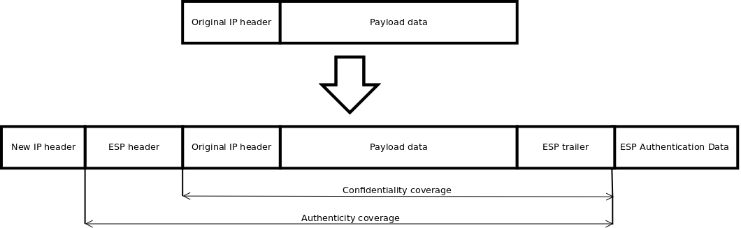
Encapsulating Security Payload (ESP)
Encapsulating Security Payload (ESP) uses shared key encryption to provide data privacy. ESP also supports its own authentication scheme like that used in AH.
ESP packages its fields in a very different way than AH. Instead of having just a header, it divides its fields into three components:
- ESP Header — Comes before the encrypted data and its placement depends on whether ESP is used in transport mode or tunnel mode.
- ESP Trailer — This section is placed after the encrypted data. It contains padding that is used to align the encrypted data.
- ESP Authentication Data — This field contains an Integrity Check Value (ICV), computed in a manner similar to how the AH protocol works, for when ESP’s optional authentication feature is used.
Transport mode
In transport mode, the ESP header is inserted after the original IP header. ESP trailer and authentication value are added to the end of the packet. In this mode only the IP payload is encrypted and authenticated, the IP header is not secured.
![]()
Tunnel mode
In tunnel mode, an original IP packet is encapsulated within a new IP packet thus securing IP payload and IP header.
Encryption algorithms
RouterOS ESP supports various encryption and authentication algorithms.
Authentication:
- MD5
- SHA1
- SHA2 (256-bit, 512-bit)
Encryption:
- AES — 128-bit, 192-bit, and 256-bit key AES-CBC, AES-CTR, and AES-GCM algorithms;
- Blowfish — added since v4.5
- Twofish — added since v4.5
- Camellia — 128-bit, 192-bit, and 256-bit key Camellia encryption algorithm added since v4.5
- DES — 56-bit DES-CBC encryption algorithm;
- 3DES — 168-bit DES encryption algorithm;
Hardware acceleration
Hardware acceleration allows doing a faster encryption process by using a built-in encryption engine inside the CPU.
List of devices with hardware acceleration is available here
| CPU | DES and 3DES | AES-CBC | AES-CTR | AES-GCM | ||||||||||||
|---|---|---|---|---|---|---|---|---|---|---|---|---|---|---|---|---|
| MD5 | SHA1 | SHA256 | SHA512 | MD5 | SHA1 | SHA256 | SHA512 | MD5 | SHA1 | SHA256 | SHA512 | MD5 | SHA1 | SHA256 | SHA512 | |
| 88F7040 | no | yes | yes | yes | no | yes | yes | yes | no | yes | yes | yes | no | yes | yes | yes |
| AL21400 | yes | yes | yes | yes | yes | yes | yes | yes | yes | yes | yes | yes | yes | yes | yes | yes |
| AL32400 | yes | yes | yes | yes | yes | yes | yes | yes | yes | yes | yes | yes | yes | yes | yes | yes |
| AL52400 | yes | yes | yes | yes | yes | yes | yes | yes | yes | yes | yes | yes | yes | yes | yes | yes |
| AL73400 | yes | yes | yes | yes | yes | yes | yes | yes | yes | yes | yes | yes | yes | yes | yes | yes |
| IPQ-4018 / IPQ-4019 | no | yes | yes | no | no | yes* | yes* | no | no | yes* | yes* | no | no | no | no | no |
| IPQ-6010 | no | no | no | no | no | yes | yes | yes | no | yes | yes | yes | no | yes | yes | yes |
| IPQ-8064 | no | yes | yes | no | no | yes* | yes* | no | no | yes* | yes* | no | no | no | no | no |
| MT7621A | yes**** | yes**** | yes**** | no | yes | yes | yes | no | no | no | no | no | no | no | no | no |
| P1023NSN5CFB | no | no | no | no | yes** | yes** | yes** | yes** | no | no | no | no | no | no | no | no |
| P202ASSE2KFB | yes | yes | yes | no | yes | yes | yes | yes | no | no | no | no | no | no | no | no |
| PPC460GT | no | no | no | no | yes*** | yes*** | yes*** | yes*** | yes*** | yes*** | yes*** | yes*** | no | no | no | no |
| TLR4 (TILE) | yes | yes | yes | no | yes | yes | yes | no | yes | yes | yes | no | no | no | no | no |
| x86 (AES-NI) | no | no | no | no | yes*** | yes*** | yes*** | yes*** | yes*** | yes*** | yes*** | yes*** | yes*** | yes*** | yes*** | yes*** |
* supported only 128 bit and 256 bit key sizes
** only manufactured since 2016, serial numbers that begin with number 5 and 7
*** AES-CBC and AES-CTR only encryption is accelerated, hashing done in software
**** DES is not supported, only 3DES and AES-CBC
IPsec throughput results of various encryption and hash algorithm combinations are published on the MikroTik products page.
Policies
The policy table is used to determine whether security settings should be applied to a packet.
Properties
| Property | Description |
|---|---|
| action (discard | encrypt | none; Default: encrypt) | Specifies what to do with the packet matched by the policy.
|
| comment (string; Default: ) | Short description of the policy. |
| disabled (yes | no; Default: no) | Whether a policy is used to match packets. |
| dst-address (IP/IPv6 prefix; Default: 0.0.0.0/32) | Destination address to be matched in packets. Applicable when tunnel mode (tunnel=yes) or template (template=yes) is used. |
| dst-port (integer:0..65535 | any; Default: any) | Destination port to be matched in packets. If set to any all ports will be matched. |
| group (string; Default: default) | Name of the policy group to which this template is assigned. |
| ipsec-protocols (ah | esp; Default: esp) | Specifies what combination of Authentication Header and Encapsulating Security Payload protocols you want to apply to matched traffic. |
| level (require | unique | use; Default: require) | Specifies what to do if some of the SAs for this policy cannot be found:
|
| peer (string; Default: ) | Name of the peer on which the policy applies. |
| proposal (string; Default: default) | Name of the proposal template that will be sent by IKE daemon to establish SAs for this policy. |
| protocol (all | egp | ggp| icmp | igmp | …; Default: all) | IP packet protocol to match. |
| src-address (ip/ipv6 prefix; Default: 0.0.0.0/32) | Source address to be matched in packets. Applicable when tunnel mode (tunnel=yes) or template (template=yes) is used. |
| src-port (any | integer:0..65535; Default: any) | Source port to be matched in packets. If set to any all ports will be matched. |
| template (yes | no; Default: no) | Creates a template and assigns it to a specified policy group.
Following parameters are used by template:
|
| tunnel (yes | no; Default: no) | Specifies whether to use tunnel mode. |
Read-only properties
| Property | Description |
|---|---|
| active (yes | no) | Whether this policy is currently in use. |
| default (yes | no) | Whether this is a default system entry. |
| dynamic (yes | no) | Whether this is a dynamically added or generated entry. |
| invalid (yes | no) | Whether this policy is invalid — the possible cause is a duplicate policy with the same src-address and dst-address. |
| ph2-count (integer) | A number of active phase 2 sessions associated with the policy. |
| ph2-state (expired | no-phase2 | established) | Indication of the progress of key establishing. |
| sa-dst-address (ip/ipv6 address; Default: ::) | SA destination IP/IPv6 address (remote peer). |
| sa-src-address (ip/ipv6 address; Default: ::) | SA source IP/IPv6 address (local peer). |
Policy order is important starting from v6.40. Now it works similarly to firewall filters where policies are executed from top to bottom (priority parameter is removed).
All packets are IPIP encapsulated in tunnel mode, and their new IP header’s src-address and dst-address are set to sa-src-address and sa-dst-address values of this policy. If you do not use tunnel mode (id est you use transport mode), then only packets whose source and destination addresses are the same as sa-src-address and sa-dst-address can be processed by this policy. Transport mode can only work with packets that originate at and are destined for IPsec peers (hosts that established security associations). To encrypt traffic between networks (or a network and a host) you have to use tunnel mode.
Statistics
This menu shows various IPsec statistics and errors.
Read-only properties
| Property | Description |
|---|---|
| in-errors (integer) | All inbound errors that are not matched by other counters. |
| in-buffer-errors (integer) | No free buffer. |
| in-header-errors (integer) | Header error. |
| in-no-states (integer) | No state is found i.e. either inbound SPI, address, or IPsec protocol at SA is wrong. |
| in-state-protocol-errors (integer) | Transformation protocol-specific error, for example, SA key is wrong or hardware accelerator is unable to handle the number of packets. |
| in-state-mode-errors (integer) | Transformation mode-specific error. |
| in-state-sequence-errors (integer) | A sequence number is out of a window. |
| in-state-expired (integer) | The state is expired. |
| in-state-mismatches (integer) | The state has a mismatched option, for example, the UDP encapsulation type is mismatched. |
| in-state-invalid (integer) | The state is invalid. |
| in-template-mismatches (integer) | No matching template for states, e.g. inbound SAs are correct but the SP rule is wrong. A possible cause is a mismatched sa-source or sa-destination address. |
| in-no-policies (integer) | No policy is found for states, e.g. inbound SAs are correct but no SP is found. |
| in-policy-blocked (integer) | Policy discards. |
| in-policy-errors (integer) | Policy errors. |
| out-errors (integer) | All outbound errors that are not matched by other counters. |
| out-bundle-errors (integer) | Bundle generation error. |
| out-bundle-check-errors (integer) | Bundle check error. |
| out-no-states (integer) | No state is found. |
| out-state-protocol-errors (integer) | Transformation protocol specific error. |
| out-state-mode-errors (integer) | Transformation mode-specific error. |
| out-state-sequence-errors (integer) | Sequence errors, for example, sequence number overflow. |
| out-state-expired (integer) | The state is expired. |
| out-policy-blocked (integer) | Policy discards. |
| out-policy-dead (integer) | The policy is dead. |
| out-policy-errors (integer) | Policy error. |
Proposals
Proposal information that will be sent by IKE daemons to establish SAs for certain policies.
Properties
| Property | Description |
|---|---|
| auth-algorithms (md5|null|sha1|sha256|sha512; Default: sha1) | Allowed algorithms for authorization. SHA (Secure Hash Algorithm) is stronger but slower. MD5 uses a 128-bit key, sha1-160bit key. |
| comment (string; Default: ) | |
| disabled (yes | no; Default: no) | Whether an item is disabled. |
| enc-algorithms (null|des|3des|aes-128-cbc|aes-128-cbc|aes-128gcm|aes-192-cbc|aes-192-ctr|aes-192-gcm|aes-256-cbc|aes-256-ctr|aes-256-gcm|blowfish|camellia-128|camellia-192|camellia-256|twofish; Default: aes-256-cbc,aes-192-cbc,aes-128-cbc) | Allowed algorithms and key lengths to use for SAs. |
| lifetime (time; Default: 30m) | How long to use SA before throwing it out. |
| name (string; Default: ) | |
| pfs-group (ecp256 | ecp384 | ecp521 | modp768 | modp1024 | modp1536 | modp2048 | modp3072 | modp4096 | modp6144 | modp8192 | none; Default: modp1024) | The diffie-Helman group used for Perfect Forward Secrecy. |
Read-only properties
| Property | Description |
|---|---|
| default (yes | no) | Whether this is a default system entry. |
Groups
In this menu, it is possible to create additional policy groups used by policy templates.
Properties
| Property | Description |
|---|---|
| name (string; Default: ) | |
| comment (string; Default: ) |
Peers
Peer configuration settings are used to establish connections between IKE daemons. This connection then will be used to negotiate keys and algorithms for SAs. Exchange mode is the only unique identifier between the peers, meaning that there can be multiple peer configurations with the same remote-address as long as a different exchange-mode is used.
Properties
| Property | Description |
|---|---|
| address (IP/IPv6 Prefix; Default: 0.0.0.0/0) | If the remote peer’s address matches this prefix, then the peer configuration is used in authentication and establishment of Phase 1. If several peer’s addresses match several configuration entries, the most specific one (i.e. the one with the largest netmask) will be used. |
| comment (string; Default: ) | Short description of the peer. |
| disabled (yes | no; Default: no) | Whether peer is used to matching remote peer’s prefix. |
| exchange-mode (aggressive | base | main | ike2; Default: main) | Different ISAKMP phase 1 exchange modes according to RFC 2408. the main mode relaxes rfc2409 section 5.4, to allow pre-shared-key authentication in the main mode. ike2 mode enables Ikev2 RFC 7296. Parameters that are ignored by IKEv2 proposal-check, compatibility-options, lifebytes, dpd-maximum-failures, nat-traversal. |
| local-address (IP/IPv6 Address; Default: ) | Routers local address on which Phase 1 should be bounded to. |
| name (string; Default: ) | |
| passive (yes | no; Default: no) | When a passive mode is enabled will wait for a remote peer to initiate an IKE connection. The enabled passive mode also indicates that the peer is xauth responder, and disabled passive mode — xauth initiator. When a passive mode is a disabled peer will try to establish not only phase1 but also phase2 automatically, if policies are configured or created during the phase1. |
| port (integer:0..65535; Default: 500) | Communication port used (when a router is an initiator) to connect to remote peer in cases if remote peer uses the non-default port. |
| profile (string; Default: default) | Name of the profile template that will be used during IKE negotiation. |
| send-initial-contact (yes | no; Default: yes) | Specifies whether to send «initial contact» IKE packet or wait for remote side, this packet should trigger the removal of old peer SAs for current source address. Usually, in road warrior setups clients are initiators and this parameter should be set to no. Initial contact is not sent if modecfg or xauth is enabled for ikev1. |
Read-only properties
| Property | Description |
|---|---|
| dynamic (yes | no) | Whether this is a dynamically added entry by a different service (e.g L2TP). |
| responder (yes | no) | Whether this peer will act as a responder only (listen to incoming requests) and not initiate a connection. |
Profiles
Profiles define a set of parameters that will be used for IKE negotiation during Phase 1. These parameters may be common with other peer configurations.
Properties
| Property | Description |
|---|---|
| dh-group (modp768 | modp1024 | modp1536 | modp2048 | modp3072 | modp4096 | modp6144 | modp8192 | ecp256 | ecp384 | ecp521; Default: modp1024,modp2048) | Diffie-Hellman group (cipher strength) |
| dpd-interval (time | disable-dpd; Default: 2m) | Dead peer detection interval. If set to disable-dpd, dead peer detection will not be used. |
| dpd-maximum-failures (integer: 1..100; Default: 5) | Maximum count of failures until peer is considered to be dead. Applicable if DPD is enabled. |
| enc-algorithm (3des | aes-128 | aes-192 | aes-256 | blowfish | camellia-128 | camellia-192 | camellia-256 | des; Default: aes-128) | List of encryption algorithms that will be used by the peer. |
| hash-algorithm (md5 | sha1 | sha256 | sha512; Default: sha1) | Hashing algorithm. SHA (Secure Hash Algorithm) is stronger, but slower. MD5 uses 128-bit key, sha1-160bit key. |
| lifebytes (Integer: 0..4294967295; Default: 0) | Phase 1 lifebytes is used only as administrative value which is added to proposal. Used in cases if remote peer requires specific lifebytes value to establish phase 1. |
| lifetime (time; Default: 1d) | Phase 1 lifetime: specifies how long the SA will be valid. |
| name (string; Default: ) | |
| nat-traversal (yes | no; Default: yes) | Use Linux NAT-T mechanism to solve IPsec incompatibility with NAT routers between IPsec peers. This can only be used with ESP protocol (AH is not supported by design, as it signs the complete packet, including the IP header, which is changed by NAT, rendering AH signature invalid). The method encapsulates IPsec ESP traffic into UDP streams in order to overcome some minor issues that made ESP incompatible with NAT. |
| proposal-check (claim | exact | obey | strict; Default: obey) | Phase 2 lifetime check logic:
|
Identities
Identities are configuration parameters that are specific to the remote peer. The main purpose of identity is to handle authentication and verify the peer’s integrity.
Properties
| Property | Description |
|---|---|
| auth-method (digital-signature | eap | eap-radius | pre-shared-key | pre-shared-key-xauth | rsa-key | rsa-signature-hybrid; Default: pre-shared-key) | Authentication method:
|
| certificate (string; Default: ) | Name of a certificate listed in System/Certificates (signing packets; the certificate must have the private key). Applicable if digital signature authentication method (auth-method=digital-signature) or EAP (auth-method=eap) is used. |
| comment (string; Default: ) | Short description of the identity. |
| disabled (yes | no; Default: no) | Whether identity is used to match remote peers. |
| eap-methods (eap-mschapv2 | eap-peap | eap-tls | eap-ttls; Default: eap-tls) | All EAP methods requires whole certificate chain including intermediate and root CA certificates to be present in System/Certificates menu. Also, the username and password (if required by the authentication server) must be specified. Multiple EAP methods may be specified and will be used in a specified order. Currently supported EAP methods:
|
| generate-policy (no | port-override | port-strict; Default: no) | Allow this peer to establish SA for non-existing policies. Such policies are created dynamically for the lifetime of SA. Automatic policies allows, for example, to create IPsec secured L2TP tunnels, or any other setup where remote peer’s IP address is not known at the configuration time.
|
| key (string; Default: ) | Name of the private key from keys menu. Applicable if RSA key authentication method (auth-method=rsa-key) is used. |
| match-by (remote-id | certificate; Default: remote-id) | Defines the logic used for peer’s identity validation.
|
| mode-config (none | *request-only | string; Default: none) | Name of the configuration parameters from mode-config menu. When parameter is set mode-config is enabled. |
| my-id (auto | address | fqdn | user-fqdn | key-id; Default: auto) | On initiator, this controls what ID_i is sent to the responder. On responder, this controls what ID_r is sent to the initiator. In IKEv2, responder also expects this ID in received ID_r from initiator.
|
| notrack-chain (string; Default: ) | Adds IP/Firewall/Raw rules matching IPsec policy to a specified chain. Use together with generate-policy. |
| password (string; Default: ) | XAuth or EAP password. Applicable if pre-shared key with XAuth authentication method (auth-method=pre-shared-key-xauth) or EAP (auth-method=eap) is used. |
| peer (string; Default: ) | Name of the peer on which the identity applies. |
| policy-template-group (none | string; Default: default) | If generate-policy is enabled, traffic selectors are checked against templates from the same group. If none of the templates match, Phase 2 SA will not be established. |
| remote-certificate (string; Default: ) | Name of a certificate (listed in System/Certificates) for authenticating the remote side (validating packets; no private key required). If a remote-certificate is not specified then the received certificate from a remote peer is used and checked against CA in the certificate menu. Proper CA must be imported in a certificate store. If remote-certificate and match-by=certificate is specified, only the specific client certificate will be matched. Applicable if digital signature authentication method (auth-method=digital-signature) is used. |
| remote-id (auto | fqdn | user-fqdn | key-id | ignore; Default: auto) | This parameter controls what ID value to expect from the remote peer. Note that all types except for ignoring will verify remote peer’s ID with a received certificate. In case when the peer sends the certificate name as its ID, it is checked against the certificate, else the ID is checked against Subject Alt. Name.
|
| remote-key (string; Default: ) | Name of the public key from keys menu. Applicable if RSA key authentication method (auth-method=rsa-key) is used. |
| secret (string; Default: ) | Secret string. If it starts with ‘0x’, it is parsed as a hexadecimal value. Applicable if pre-shared key authentication method (auth-method=pre-shared-key and auth-method=pre-shared-key-xauth) is used. |
| username (string; Default: ) | XAuth or EAP username. Applicable if pre-shared key with XAuth authentication method (auth-method=pre-shared-key-xauth) or EAP (auth-method=eap) is used. |
Read only properties
| Property | Description |
|---|---|
| dynamic (yes | no) | Whether this is a dynamically added entry by a different service (e.g L2TP). |
Active Peers
This menu provides various statistics about remote peers that currently have established phase 1 connection.
Read only properties
| Property | Description |
|---|---|
| dynamic-address (ip/ipv6 address) | Dynamically assigned an IP address by mode config |
| last-seen (time) | Duration since the last message received by this peer. |
| local-address (ip/ipv6 address) | Local address on the router used by this peer. |
| natt-peer (yes | no) | Whether NAT-T is used for this peer. |
| ph2-total (integer) | The total amount of active IPsec security associations. |
| remote-address (ip/ipv6 address) | The remote peer’s ip/ipv6 address. |
| responder (yes | no) | Whether the connection is initiated by a remote peer. |
| rx-bytes (integer) | The total amount of bytes received from this peer. |
| rx-packets (integer) | The total amount of packets received from this peer. |
| side (initiator | responder) | Shows which side initiated the Phase1 negotiation. |
| state (string) | State of phase 1 negotiation with the peer. For example, when phase1 and phase 2 are negotiated it will show state «established». |
| tx-bytes (integer) | The total amount of bytes transmitted to this peer. |
| tx-packets (integer) | The total amount of packets transmitted to this peer. |
| uptime (time) | How long peers are in an established state. |
Commands
| Property | Description |
|---|---|
| kill-connections () | Manually disconnects all remote peers. |
Mode configs
ISAKMP and IKEv2 configuration attributes are configured in this menu.
Properties
| Property | Description |
|---|---|
| address (none | string; Default: ) | Single IP address for the initiator instead of specifying a whole address pool. |
| address-pool (none | string; Default: ) | Name of the address pool from which the responder will try to assign address if mode-config is enabled. |
| address-prefix-length (integer [1..32]; Default: ) | Prefix length (netmask) of the assigned address from the pool. |
| comment (string; Default: ) | |
| name (string; Default: ) | |
| responder (yes | no; Default: no) | Specifies whether the configuration will work as an initiator (client) or responder (server). The initiator will request for mode-config parameters from the responder. |
| split-dns | List of DNS names that will be resolved using a system-dns=yes or static-dns= setting. |
| split-include (list of IP prefix; Default: ) | List of subnets in CIDR format, which to tunnel. Subnets will be sent to the peer using the CISCO UNITY extension, a remote peer will create specific dynamic policies. |
| src-address-list (address list; Default: ) | Specifying an address list will generate dynamic source NAT rules. This parameter is only available with responder=no. A roadWarrior client with NAT |
| static-dns (list of IP; Default: ) | Manually specified DNS server’s IP address to be sent to the client. |
| system-dns (yes | no; Default: ) | When this option is enabled DNS addresses will be taken from /ip dns. |
Read-only properties
| Property | Description |
|---|---|
| default (yes | no) | Whether this is a default system entry. |
Not all IKE implementations support multiple split networks provided by the split-include option.
If RouterOS client is initiator, it will always send CISCO UNITY extension, and RouterOS supports only split-include from this extension.
Both attributes Cisco Unity Split DNS (attribute type 28675) and RFC8598 (attribute type 25) are supported, ROS will answer to these attributes but only as responder.
It is not possible to use system-dns and static-dns at the same time, ROS can use only one DNS.
Installed SAs
This menu provides information about installed security associations including the keys.
Read-only properties
| Property | Description |
|---|---|
| AH (yes | no) | Whether AH protocol is used by this SA. |
| ESP (yes | no) | Whether ESP protocol is used by this SA. |
| add-lifetime (time/time) | Added lifetime for the SA in format soft/hard:
|
| addtime (time) | Date and time when this SA was added. |
| auth-algorithm (md5 | null | sha1 | …) | Currently used authentication algorithm. |
| auth-key (string) | Used authentication key. |
| current-bytes (64-bit integer) | A number of bytes seen by this SA. |
| dst-address (IP) | The destination address of this SA. |
| enc-algorithm (des | 3des | aes-cbc | …) | Currently used encryption algorithm. |
| enc-key (string) | Used encryption key. |
| enc-key-size (number) | Used encryption key length. |
| expires-in (yes | no) | Time left until rekeying. |
| hw-aead (yes | no) | Whether this SA is hardware accelerated. |
| replay (integer) | Size of replay window in bytes. |
| spi (string) | Security Parameter Index identification tag |
| src-address (IP) | The source address of this SA. |
| state (string) | Shows the current state of the SA («mature», «dying» etc) |
Commands
| Property | Description |
|---|---|
| flush () | Manually removes all installed security associations. |
Keys
This menu lists all imported public and private keys, that can be used for peer authentication. Menu has several commands to work with keys.
Properties
| Property | Description |
|---|---|
| name (string; Default: ) |
Read-only properties
| Property | Description |
|---|---|
| key-size (1024 | 2048 | 4096) | Size of this key. |
| private-key (yes | no) | Whether this is a private key. |
| rsa (yes | no) | Whether this is an RSA key. |
Commands
| Property | Description |
|---|---|
| export-pub-key (file-name; key) | Export public key to file from one of existing private keys. |
| generate-key (key-size; name) | Generate a private key. Takes two parameters, name of the newly generated key and key size 1024,2048 and 4096. |
| import (file-name; name) | Import key from file. |
Settings
| Property | Description |
|---|---|
| accounting (yes | no; Default: ) | Whether to send RADIUS accounting requests to a RADIUS server. Applicable if EAP Radius (auth-method=eap-radius) or pre-shared key with XAuth authentication method (auth-method=pre-shared-key-xauth) is used. |
| interim-update (time; Default: ) | The interval between each consecutive RADIUS accounting Interim update. Accounting must be enabled. |
| xauth-use-radius (yes | no; Default: ) | Whether to use Radius client for XAuth users or not. Property is only applicable to peers using the IKEv1 exchange mode. |
Application Guides
RoadWarrior client with NAT
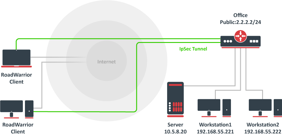
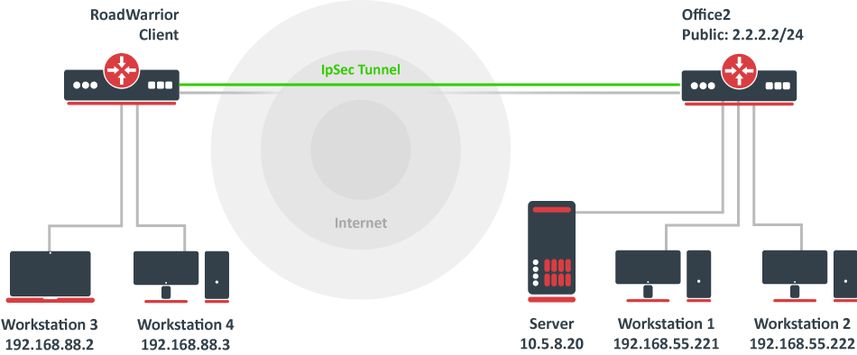
Consider setup as illustrated below. RouterOS acts as a RoadWarrior client connected to Office allowing access to its internal resources.
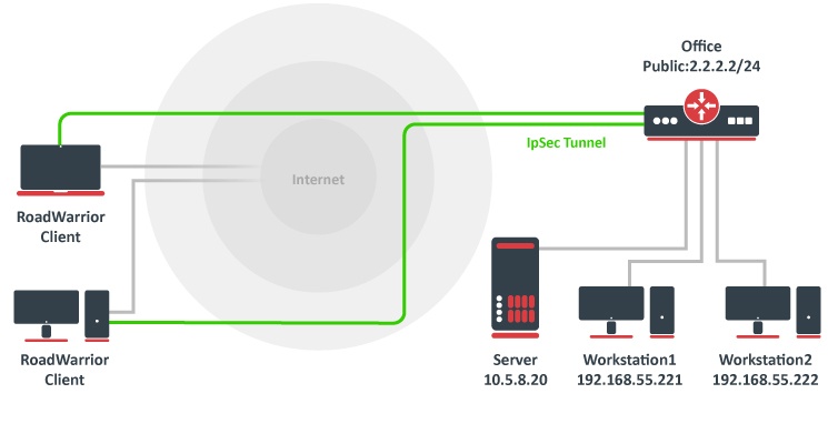
A tunnel is established, a local mode-config IP address is received and a set of dynamic policies are generated.
[admin@mikrotik] > ip ipsec policy print
Flags: T - template, X - disabled, D - dynamic, I - invalid, A - active, * - default
0 T * group=default src-address=::/0 dst-address=::/0 protocol=all proposal=default template=yes

1 DA src-address=192.168.77.254/32 src-port=any dst-address=10.5.8.0/24 dst-port=any protocol=all
action=encrypt level=unique ipsec-protocols=esp tunnel=yes sa-src-address=10.155.107.8
sa-dst-address=10.155.107.9 proposal=default ph2-count=1

2 DA src-address=192.168.77.254/32 src-port=any dst-address=192.168.55.0/24 dst-port=any protocol=all
action=encrypt level=unique ipsec-protocols=esp tunnel=yes sa-src-address=10.155.107.8
sa-dst-address=10.155.107.9 proposal=default ph2-count=1
Currently, only packets with a source address of 192.168.77.254/32 will match the IPsec policies. For a local network to be able to reach remote subnets, it is necessary to change the source address of local hosts to the dynamically assigned mode config IP address. It is possible to generate source NAT rules dynamically. This can be done by creating a new address list that contains all local networks that the NAT rule should be applied. In our case, it is 192.168.88.0/24.
/ip firewall address-list add address=192.168.88.0/24 list=local-RW
By specifying the address list under the mode-config initiator configuration, a set of source NAT rules will be dynamically generated.
/ip ipsec mode-config set [ find name="request-only" ] src-address-list=local-RW
When the IPsec tunnel is established, we can see the dynamically created source NAT rules for each network. Now every host in 192.168.88.0/24 is able to access Office’s internal resources.
[admin@mikrotik] > ip firewall nat print
Flags: X - disabled, I - invalid, D - dynamic
0 D ;;; ipsec mode-config
chain=srcnat action=src-nat to-addresses=192.168.77.254 dst-address=192.168.55.0/24 src-address-list=local-RW

1 D ;;; ipsec mode-config
chain=srcnat action=src-nat to-addresses=192.168.77.254 dst-address=10.5.8.0/24 src-address-list=local-RW
Allow only IPsec encapsulated traffic
There are some scenarios where for security reasons you would like to drop access from/to specific networks if incoming/outgoing packets are not encrypted. For example, if we have L2TP/IPsec setup we would want to drop nonencrypted L2TP connection attempts.
There are several ways how to achieve this:
- Using IPsec policy matcher in firewall;
- Using generic IPsec policy with action set to drop and lower priority (can be used in Road Warrior setups where dynamic policies are generated);
- By setting DSCP or priority in mangle and matching the same values in firewall after decapsulation.
IPsec policy matcher
Let’s set up an IPsec policy matcher to accept all packets that matched any of the IPsec policies and drop the rest:
add chain=input comment="ipsec policy matcher" in-interface=WAN ipsec-policy=in,ipsec
add action=drop chain=input comment="drop all" in-interface=WAN log=yes
IPsec policy matcher takes two parameters direction, policy. We used incoming direction and IPsec policy. IPsec policy option allows us to inspect packets after decapsulation, so for example, if we want to allow only GRE encapsulated packet from a specific source address and drop the rest we could set up the following rules:
add chain=input comment="ipsec policy matcher" in-interface=WAN ipsec-policy=in,ipsec protocol=gre src=address=192.168.33.1
add action=drop chain=input comment="drop all" in-interface=WAN log=yes
For L2TP rule set would be:
add chain=input comment="ipsec policy matcher" in-interface=WAN ipsec-policy=in,ipsec protocol=udp dst-port=1701
add action=drop chain=input protocol=udp dst-port=1701 comment="drop l2tp" in-interface=WAN log=yes
Using generic IPsec policy
The trick of this method is to add a default policy with an action drop. Let’s assume we are running an L2TP/IPsec server on a public 1.1.1.1 address and we want to drop all nonencrypted L2TP:
/ip ipsec policy
add src-address=1.1.1.1 dst-address=0.0.0.0/0 sa-src-address=1.1.1.1 protocol=udp src-port=1701 tunnel=yes action=discard
Now router will drop any L2TP unencrypted incoming traffic, but after a successful L2TP/IPsec connection dynamic policy is created with higher priority than it is on default static rule, and packets matching that dynamic rule can be forwarded.
Policy order is important! For this to work, make sure the static drop policy is below the dynamic policies. Move it below the policy template if necessary.
[admin@rack2_10g1] /ip ipsec policy> print
Flags: T - template, X - disabled, D - dynamic, I - inactive, * - default
0 T * group=default src-address=::/0 dst-address=::/0 protocol=all
proposal=default template=yes

1 D src-address=1.1.1.1/32 src-port=1701 dst-address=10.5.130.71/32
dst-port=any protocol=udp action=encrypt level=require
ipsec-protocols=esp tunnel=no sa-src-address=1.1.1.1
sa-dst-address=10.5.130.71

2 src-address=1.1.1.1/32 src-port=1701 dst-address=0.0.0.0/0
dst-port=any protocol=udp action=discard level=unique
ipsec-protocols=esp tunnel=yes sa-src-address=1.1.1.1
sa-dst-address=0.0.0.0 proposal=default manual-sa=none
Manually specifying local-address parameter under Peer configuration
Using different routing table
IPsec, as any other service in RouterOS, uses the main routing table regardless of what local-address parameter is used for Peer configuration. It is necessary to apply routing marks to both IKE and IPSec traffic.
Consider the following example. There are two default routes — one in the main routing table and another in the routing table «backup». It is necessary to use the backup link for the IPsec site to site tunnel.
[admin@pair_r1] > /ip route print detail
Flags: X - disabled, A - active, D - dynamic, C - connect, S - static, r - rip, b - bgp, o - ospf, m - mme, B - blackhole, U - unreachable, P - prohibit
0 A S dst-address=0.0.0.0/0 gateway=10.155.107.1 gateway-status=10.155.107.1 reachable via ether1 distance=1 scope=30 target-scope=10 routing-mark=backup

1 A S dst-address=0.0.0.0/0 gateway=172.22.2.115 gateway-status=172.22.2.115 reachable via ether2 distance=1 scope=30 target-scope=10

2 ADC dst-address=10.155.107.0/25 pref-src=10.155.107.8 gateway=ether1 gateway-status=ether1 reachable distance=0 scope=10

3 ADC dst-address=172.22.2.0/24 pref-src=172.22.2.114 gateway=ether2 gateway-status=ether2 reachable distance=0 scope=10

4 ADC dst-address=192.168.1.0/24 pref-src=192.168.1.1 gateway=bridge-local gateway-status=ether2 reachable distance=0 scope=10

[admin@pair_r1] > /ip firewall nat print
Flags: X - disabled, I - invalid, D - dynamic
0 chain=srcnat action=masquerade out-interface=ether1 log=no log-prefix=""

1 chain=srcnat action=masquerade out-interface=ether2 log=no log-prefix=""
IPsec peer and policy configurations are created using the backup link’s source address, as well as the NAT bypass rule for IPsec tunnel traffic.
/ip ipsec peer
add address=10.155.130.136/32 local-address=10.155.107.8 secret=test
/ip ipsec policy
add sa-src-address=10.155.107.8 src-address=192.168.1.0/24 dst-address=172.16.0.0/24 sa-dst-address=10.155.130.136 tunnel=yes
/ip firewall nat
add action=accept chain=srcnat src-address=192.168.1.0/24 dst-address=172.16.0.0/24 place-before=0
Currently, we see «phase1 negotiation failed due to time up» errors in the log. It is because IPsec tries to reach the remote peer using the main routing table with an incorrect source address. It is necessary to mark UDP/500, UDP/4500, and ipsec-esp packets using Mangle:
/ip firewall mangle
add action=mark-connection chain=output connection-mark=no-mark dst-address=10.155.130.136 dst-port=500,4500 new-connection-mark=ipsec passthrough=yes protocol=udp
add action=mark-connection chain=output connection-mark=no-mark dst-address=10.155.130.136 new-connection-mark=ipsec passthrough=yes protocol=ipsec-esp
add action=mark-routing chain=output connection-mark=ipsec new-routing-mark=backup passthrough=no
Using the same routing table with multiple IP addresses
Consider the following example. There are multiple IP addresses from the same subnet on the public interface. Masquerade rule is configured on out-interface. It is necessary to use one of the IP addresses explicitly.
[admin@pair_r1] > /ip address print
Flags: X - disabled, I - invalid, D - dynamic
# ADDRESS NETWORK INTERFACE
0 192.168.1.1/24 192.168.1.0 bridge-local
1 172.22.2.1/24 172.22.2.0 ether1
2 172.22.2.2/24 172.22.2.0 ether1
3 172.22.2.3/24 172.22.2.0 ether1

[admin@pair_r1] > /ip route print
Flags: X - disabled, A - active, D - dynamic, C - connect, S - static, r - rip, b - bgp, o - ospf, m - mme, B - blackhole, U - unreachable, P - prohibit
# DST-ADDRESS PREF-SRC GATEWAY DISTANCE
1 A S 0.0.0.0/0 172.22.2.115 1
3 ADC 172.22.2.0/24 172.22.2.1 ether1 0
4 ADC 192.168.1.0/24 192.168.1.1 bridge-local 0

[admin@pair_r1] /ip firewall nat> print
Flags: X - disabled, I - invalid, D - dynamic
0 chain=srcnat action=masquerade out-interface=ether1 log=no log-prefix=""
IPsec peer and policy configuration is created using one of the public IP addresses.
/ip ipsec peer
add address=10.155.130.136/32 local-address=172.22.2.3 secret=test
/ip ipsec policy
add sa-src-address=172.22.2.3 src-address=192.168.1.0/24 dst-address=172.16.0.0/24 sa-dst-address=10.155.130.136 tunnel=yes
/ip firewall nat
add action=accept chain=srcnat src-address=192.168.1.0/24 dst-address=172.16.0.0/24 place-before=0
Currently, the phase 1 connection uses a different source address than we specified, and «phase1 negotiation failed due to time up» errors are shown in the logs. This is because masquerade is changing the source address of the connection to match the pref-src address of the connected route. The solution is to exclude connections from the public IP address from being masqueraded.
/ip firewall nat
add action=accept chain=srcnat protocol=udp src-port=500,4500 place-before=0
Application examples
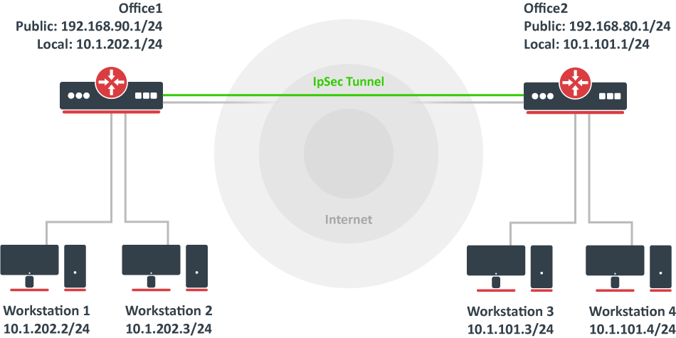
Site to Site IPsec (IKEv1) tunnel
Consider setup as illustrated below. Two remote office routers are connected to the internet and office workstations are behind NAT. Each office has its own local subnet, 10.1.202.0/24 for Office1 and 10.1.101.0/24 for Office2. Both remote offices need secure tunnels to local networks behind routers.
Site 1 configuration
Start off by creating a new Phase 1profileand Phase 2proposalentries using stronger or weaker encryption parameters that suit your needs. It is advised to create separate entries for each menu so that they are unique for each peer in case it is necessary to adjust any of the settings in the future. These parameters must match between the sites or else the connection will not establish.
/ip ipsec profile
add dh-group=modp2048 enc-algorithm=aes-128 name=ike1-site2
/ip ipsec proposal
add enc-algorithms=aes-128-cbc name=ike1-site2 pfs-group=modp2048
Continue by configuring a peer. Specify the address of the remote router. This address should be reachable through UDP/500 and UDP/4500 ports, so make sure appropriate actions are taken regarding the router’s firewall. Specify the name for this peer as well as the newly created profile.
/ip ipsec peer
add address=192.168.80.1/32 name=ike1-site2 profile=ike1-site2
The next step is to create an identity. For a basic pre-shared key secured tunnel, there is nothing much to set except for a strong secret and the peer to which this identity applies.
/ip ipsec identity
add peer=ike1-site2 secret=thisisnotasecurepsk
If security matters, consider using IKEv2 and a different auth-method.
Lastly, create a policy that controls the networks/hosts between whom traffic should be encrypted.
/ip ipsec policy
add src-address=10.1.202.0/24 src-port=any dst-address=10.1.101.0/24 dst-port=any tunnel=yes action=encrypt proposal=ike1-site2 peer=ike1-site2
Site 2 configuration
Office 2 configuration is almost identical to Office 1 with proper IP address configuration. Start off by creating a new Phase 1 profile and Phase 2 proposal entries:
/ip ipsec profile
add dh-group=modp2048 enc-algorithm=aes-128 name=ike1-site1
/ip ipsec proposal
add enc-algorithms=aes-128-cbc name=ike1-site1 pfs-group=modp2048
Next is the peer and identity:
/ip ipsec peer
add address=192.168.90.1/32 name=ike1-site1 profile=ike1-site1
/ip ipsec identity
add peer=ike1-site1 secret=thisisnotasecurepsk
When it is done, create a policy:
/ip ipsec policy
add src-address=10.1.101.0/24 src-port=any dst-address=10.1.202.0/24 dst-port=any tunnel=yes action=encrypt proposal=ike1-site1 peer=ike1-site1
At this point, the tunnel should be established and two IPsec Security Associations should be created on both routers:
/ip ipsec
active-peers print
installed-sa print
NAT and Fasttrack Bypass
At this point if you try to send traffic over the IPsec tunnel, it will not work, packets will be lost. This is because both routers have NAT rules (masquerade) that are changing source addresses before a packet is encrypted. A router is unable to encrypt the packet because the source address does not match the address specified in the policy configuration. For more information see the IPsec packet flow example.
To fix this we need to set up IP/Firewall/NAT bypass rule.
Office 1 router:
/ip firewall nat
add chain=srcnat action=accept place-before=0 src-address=10.1.202.0/24 dst-address=10.1.101.0/24
Office 2 router:
/ip firewall nat
add chain=srcnat action=accept place-before=0 src-address=10.1.101.0/24 dst-address=10.1.202.0/24
If you previously tried to establish an IP connection before the NAT bypass rule was added, you have to clear the connection table from the existing connection or restart both routers.
It is very important that the bypass rule is placed at the top of all other NAT rules.
Another issue is if you have IP/Fasttrack enabled, the packet bypasses IPsec policies. So we need to add accept rule before FastTrack.
/ip firewall filter
add chain=forward action=accept place-before=1
src-address=10.1.101.0/24 dst-address=10.1.202.0/24 connection-state=established,related
add chain=forward action=accept place-before=1
src-address=10.1.202.0/24 dst-address=10.1.101.0/24 connection-state=established,related
However, this can add a significant load to the router’s CPU if there is a fair amount of tunnels and significant traffic on each tunnel.
The solution is to use IP/Firewall/Raw to bypass connection tracking, that way eliminating the need for filter rules listed above and reducing the load on CPU by approximately 30%.
/ip firewall raw
add action=notrack chain=prerouting src-address=10.1.101.0/24 dst-address=10.1.202.0/24
add action=notrack chain=prerouting src-address=10.1.202.0/24 dst-address=10.1.101.0/24
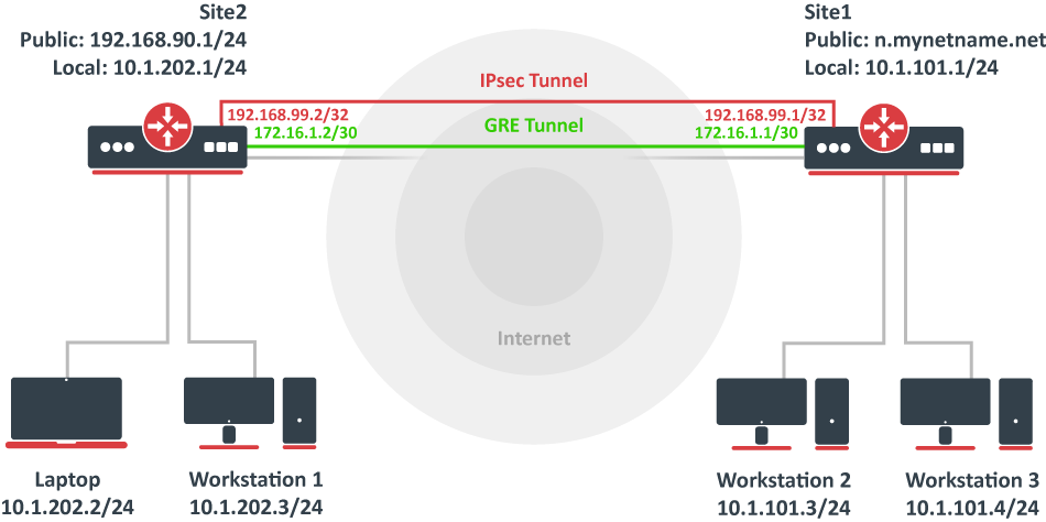
Site to Site GRE tunnel over IPsec (IKEv2) using DNS
This example explains how it is possible to establish a secure and encrypted GRE tunnel between two RouterOS devices when one or both sites do not have a static IP address. Before making this configuration possible, it is necessary to have a DNS name assigned to one of the devices which will act as a responder (server). For simplicity, we will use RouterOS built-in DDNS service IP/Cloud.
Site 1 (server) configuration
This is the side that will listen to incoming connections and act as a responder. We will use mode config to provide an IP address for the second site, but first, create a loopback (blank) bridge and assign an IP address to it that will be used later for GRE tunnel establishment.
/interface bridge
add name=loopback
/ip address
add address=192.168.99.1 interface=loopback
Continuing with the IPsec configuration, start off by creating a new Phase 1 profile and Phase 2 proposal entries using stronger or weaker encryption parameters that suit your needs. Note that this configuration example will listen to all incoming IKEv2 requests, meaning the profile configuration will be shared between all other configurations (e.g. RoadWarrior).
/ip ipsec profile
add dh-group=ecp256,modp2048,modp1024 enc-algorithm=aes-256,aes-192,aes-128 name=ike2
/ip ipsec proposal
add auth-algorithms=null enc-algorithms=aes-128-gcm name=ike2-gre pfs-group=none
Next, create a new mode config entry with responder=yes. This will provide an IP configuration for the other site as well as the host (loopback address) for policy generation.
/ip ipsec mode-config
add address=192.168.99.2 address-prefix-length=32 name=ike2-gre split-include=192.168.99.1/32 system-dns=no
It is advised to create a new policy group to separate this configuration from any existing or future IPsec configuration.
/ip ipsec policy group
add name=ike2-gre
Now it is time to set up a new policy template that will match the remote peers new dynamic address and the loopback address.
/ip ipsec policy
add dst-address=192.168.99.2/32 group=ike2-gre proposal=ike2-gre src-address=192.168.99.1/32 template=yes
The next step is to create a peer configuration that will listen to all IKEv2 requests. If you already have such an entry, you can skip this step.
/ip ipsec peer
add exchange-mode=ike2 name=ike2 passive=yes profile=ike2
Lastly, set up an identity that will match our remote peer by pre-shared-key authentication with a specific secret.
/ip ipsec identity
add generate-policy=port-strict mode-config=ike2-gre peer=ike2 policy-template-group=ike2-gre secret=test
The server side is now configured and listening to all IKEv2 requests. Please make sure the firewall is not blocking UDP/4500 port.
The last step is to create the GRE interface itself. This can also be done later when an IPsec connection is established from the client-side.
/interface gre
add local-address=192.168.99.1 name=gre-tunnel1 remote-address=192.168.99.2
Configure IP address and route to remote network through GRE interface.
/ip address
add address=172.16.1.1/30 interface=gre-tunnel1
/ip route
add dst-network=10.1.202.0/24 gateway=172.16.1.2
Site 2 (client) configuration
Similarly to server configuration, start off by creating a new Phase 1 profile and Phase 2 proposal configurations. Since this site will be the initiator, we can use a more specific profile configuration to control which exact encryption parameters are used, just make sure they overlap with what is configured on the server-side.
/ip ipsec profile
add dh-group=ecp256 enc-algorithm=aes-256 name=ike2-gre
/ip ipsec proposal
add auth-algorithms=null enc-algorithms=aes-128-gcm name=ike2-gre pfs-group=none
Next, create a new mode config entry with responder=no. This will make sure the peer requests IP and split-network configuration from the server.
/ip ipsec mode-config
add name=ike2-gre responder=no
It is also advised to create a new policy group to separate this configuration from any existing or future IPsec configuration.
/ip ipsec policy group
add name=ike2-gre
Create a new policy template on the client-side as well.
/ip ipsec policy
add dst-address=192.168.99.1/32 group=ike2-gre proposal=ike2-gre src-address=192.168.99.2/32 template=yes
Move on to peer configuration. Now we can specify the DNS name for the server under the address parameter. Obviously, you can use an IP address as well.
/ip ipsec peer
add address=n.mynetname.net exchange-mode=ike2 name=p1.ez profile=ike2-gre
Lastly, create an identity for our newly created peers.
/ip ipsec identity
add generate-policy=port-strict mode-config=ike2-gre peer=p1.ez policy-template-group=ike2-gre secret=test
If everything was done properly, there should be a new dynamic policy present.
/ip ipsec policy print
Flags: T - template, X - disabled, D - dynamic, I - invalid, A - active, * - default
0 T * group=default src-address=::/0 dst-address=::/0 protocol=all proposal=default template=yes

1 T group=ike2-gre src-address=192.168.99.2/32 dst-address=192.168.99.1/32 protocol=all proposal=ike2-gre template=yes

2 DA src-address=192.168.99.2/32 src-port=any dst-address=192.168.99.1/32 dst-port=any protocol=all action=encrypt level=unique ipsec-protocols=esp
tunnel=yes sa-src-address=192.168.90.1 sa-dst-address=(current IP of n.mynetname.net) proposal=ike2-gre ph2-count=1
A secure tunnel is now established between both sites which will encrypt all traffic between 192.168.99.2 <=> 192.168.99.1 addresses. We can use these addresses to create a GRE tunnel.
/interface gre
add local-address=192.168.99.2 name=gre-tunnel1 remote-address=192.168.99.1
Configure IP address and route to remote network through GRE interface.
/ip address
add address=172.16.1.2/30 interface=gre-tunnel1
/ip route
add dst-network=10.1.101.0/24 gateway=172.16.1.1
Road Warrior setup using IKEv2 with RSA authentication
This example explains how to establish a secure IPsec connection between a device connected to the Internet (road warrior client) and a device running RouterOS acting as a server.
RouterOS server configuration
Before configuring IPsec, it is required to set up certificates. It is possible to use a separate Certificate Authority for certificate management, however in this example, self-signed certificates are generated in RouterOS System/Certificates menu. Some certificate requirements should be met to connect various devices to the server:
- Common name should contain IP or DNS name of the server;
- SAN (subject alternative name) should have IP or DNS of the server;
- EKU (extended key usage) tls-server and tls-client are required.
Considering all requirements above, generate CA and server certificates:
/certificate
add common-name=ca name=ca
sign ca ca-crl-host=2.2.2.2
add common-name=2.2.2.2 subject-alt-name=IP:2.2.2.2 key-usage=tls-server name=server1
sign server1 ca=ca
Now that valid certificates are created on the router, add a new Phase 1 profile and Phase 2 proposal entries with pfs-group=none:
/ip ipsec profile
add name=ike2
/ip ipsec proposal
add name=ike2 pfs-group=none
Mode config is used for address distribution from IP/Pools:
/ip pool
add name=ike2-pool ranges=192.168.77.2-192.168.77.254
/ip ipsec mode-config
add address-pool=ike2-pool address-prefix-length=32 name=ike2-conf
Since that the policy template must be adjusted to allow only specific network policies, it is advised to create a separate policy group and template.
/ip ipsec policy group
add name=ike2-policies
/ip ipsec policy
add dst-address=192.168.77.0/24 group=ike2-policies proposal=ike2 src-address=0.0.0.0/0 template=yes
Create a new IPsec peer entry that will listen to all incoming IKEv2 requests.
/ip ipsec peer
add exchange-mode=ike2 name=ike2 passive=yes profile=ike2
Identity configuration
The identity menu allows to match specific remote peers and assign different configurations for each one of them. First, create a default identity, that will accept all peers, but will verify the peer’s identity with its certificate.
/ip ipsec identity
add auth-method=digital-signature certificate=server1 generate-policy=port-strict mode-config=ike2-conf peer=ike2 policy-template-group=ike2-policies
If the peer’s ID (ID_i) is not matching with the certificate it sends, the identity lookup will fail. See remote-id in the identities section.
For example, we want to assign a different mode config for user «A», who uses certificate «rw-client1» to authenticate itself to the server. First of all, make sure a new mode config is created and ready to be applied for the specific user.
/ip ipsec mode-config
add address=192.168.66.2 address-prefix-length=32 name=usr_A split-include=192.168.55.0/24 system-dns=no
It is possible to apply this configuration for user «A» by using the match-by=certificate parameter and specifying his certificate with remote-certificate.
/ip ipsec identity
add auth-method=digital-signature certificate=server1 generate-policy=port-strict match-by=certificate mode-config=usr_A peer=ike2 policy-template-group=ike2-policies remote-certificate=rw-client1
(Optional) Split tunnel configuration
Split tunneling is a method that allows road warrior clients to only access a specific secured network and at the same time send the rest of the traffic based on their internal routing table (as opposed to sending all traffic over the tunnel). To configure split tunneling, changes to mode config parameters are needed.
For example, we will allow our road warrior clients to only access the 10.5.8.0/24 network.
/ip ipsec mode-conf
set [find name="rw-conf"] split-include=10.5.8.0/24
It is also possible to send a specific DNS server for the client to use. By default, system-dns=yes is used, which sends DNS servers that are configured on the router itself in IP/DNS. We can force the client to use a different DNS server by using the static-dns parameter.
/ip ipsec mode-conf
set [find name="rw-conf"] system-dns=no static-dns=10.5.8.1
While it is possible to adjust the IPsec policy template to only allow road warrior clients to generate policies to network configured by split-include parameter, this can cause compatibility issues with different vendor implementations (see known limitations). Instead of adjusting the policy template, allow access to a secured network in IP/Firewall/Filter and drop everything else.
/ip firewall filter
add action=drop chain=forward src-address=192.168.77.0/24 dst-address=!10.5.8.0/24
Split networking is not a security measure. The client (initiator) can still request a different Phase 2 traffic selector.
Generating client certificates
To generate a new certificate for the client and sign it with a previously created CA.
/certificate
add common-name=rw-client1 name=rw-client1 key-usage=tls-client
sign rw-client1 ca=ca
PKCS12 format is accepted by most client implementations, so when exporting the certificate, make sure PKCS12 is specified.
/certificate
export-certificate rw-client1 export-passphrase=1234567890 type=pkcs12
A file named cert_export_rw-client1.p12 is now located in the routers System/File section. This file should be securely transported to the client’s device.
Typically PKCS12 bundle contains also a CA certificate, but some vendors may not install this CA, so a self-signed CA certificate must be exported separately using PEM format.
/certificate
export-certificate ca type=pem
A file named cert_export_ca.crt is now located in the routers System/File section. This file should also be securely transported to the client’s device.
PEM is another certificate format for use in client software that does not support PKCS12. The principle is pretty much the same.
/certificate
export-certificate ca
export-certificate rw-client1 export-passphrase=1234567890
Three files are now located in the routers Files section: cert_export_ca.crt, cert_export_rw-client1.crt and cert_export_rw-client1.key which should be securely transported to the client device.
Known limitations
Here is a list of known limitations by popular client software IKEv2 implementations.
- Windows will always ignore networks received by split-include and request policy with destination 0.0.0.0/0 (TSr). When IPsec-SA is generated, Windows requests DHCP option 249 to which RouterOS will respond with configured split-include networks automatically.
- Both Apple macOS and iOS will only accept the first split-include network.
- Both Apple macOS and iOS will use the DNS servers from system-dns and static-dns parameters only when 0.0.0.0/0 split-include is used.
- While some implementations can make use of different PFS group for phase 2, it is advised to use pfs-group=none under proposals to avoid any compatibility issues.
RouterOS client configuration
Import a PKCS12 format certificate in RouterOS.
/certificate import file-name=cert_export_RouterOS_client.p12 passphrase=1234567890
There should now be the self-signed CA certificate and the client certificate in the Certificate menu. Find out the name of the client certificate.
cert_export_RouterOS_client.p12_0 is the client certificate.
It is advised to create a separate Phase 1 profile and Phase 2 proposal configurations to not interfere with any existing IPsec configuration.
/ip ipsec profile
add name=ike2-rw
/ip ipsec proposal
add name=ike2-rw pfs-group=none
While it is possible to use the default policy template for policy generation, it is better to create a new policy group and template to separate this configuration from any other IPsec configuration.
/ip ipsec policy group
add name=ike2-rw
/ip ipsec policy
add group=ike2-rw proposal=ike2-rw template=yes
Create a new mode config entry with responder=no that will request configuration parameters from the server.
/ip ipsec mode-config
add name=ike2-rw responder=no
Lastly, create peer and identity configurations.
/ip ipsec peer
add address=2.2.2.2/32 exchange-mode=ike2 name=ike2-rw-client
/ip ipsec identity
add auth-method=digital-signature certificate=cert_export_RouterOS_client.p12_0 generate-policy=port-strict mode-config=ike2-rw peer=ike2-rw-client policy-template-group=ike2-rw
Verify that the connection is successfully established.
/ip ipsec
active-peers print
installed-sa print
Enabling dynamic source NAT rule generation
If we look at the generated dynamic policies, we see that only traffic with a specific (received by mode config) source address will be sent through the tunnel. But a router in most cases will need to route a specific device or network through the tunnel. In such case, we can use source NAT to change the source address of packets to match the mode config address. Since the mode config address is dynamic, it is impossible to create a static source NAT rule. In RouterOS, it is possible to generate dynamic source NAT rules for mode config clients.
For example, we have a local network 192.168.88.0/24 behind the router and we want all traffic from this network to be sent over the tunnel. First of all, we have to make a new IP/Firewall/Address list which consists of our local network
/ip firewall address-list
add address=192.168.88.0/24 list=local
When it is done, we can assign the newly created IP/Firewall/Address list to the mode config configuration.
/ip ipsec mode-config
set [ find name=ike2-rw ] src-address-list=local
Verify correct source NAT rule is dynamically generated when the tunnel is established.
[admin@MikroTik] > /ip firewall nat print
Flags: X - disabled, I - invalid, D - dynamic
0 D ;;; ipsec mode-config
chain=srcnat action=src-nat to-addresses=192.168.77.254 src-address-list=local dst-address-list=!local
Make sure the dynamic mode config address is not a part of a local network.
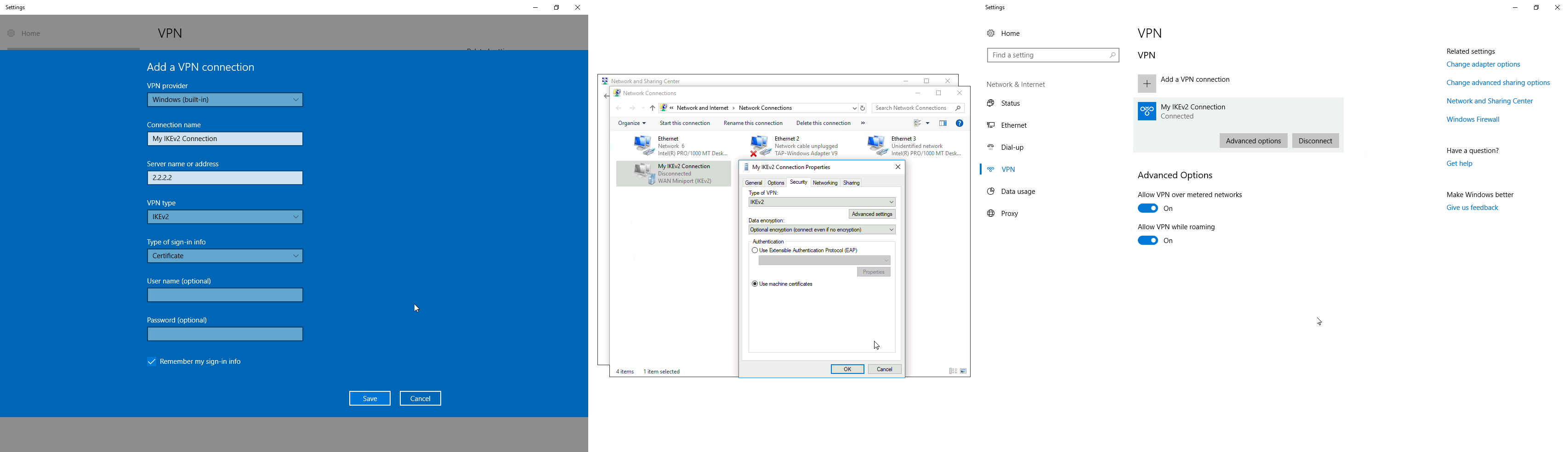
Windows client configuration
Open PKCS12 format certificate file on the Windows computer. Install the certificate by following the instructions. Make sure you select the Local Machine store location.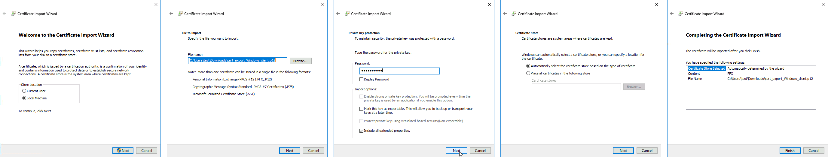 You can now proceed to Network and Internet settings -> VPN and add a new configuration. Fill in the Connection name, Server name, or address parameters. Select IKEv2 under VPN type. When it is done, it is necessary to select «Use machine certificates». This can be done in Network and Sharing Center by clicking the Properties menu for the VPN connection. The setting is located under the Security tab.
Currently, Windows 10 is compatible with the following Phase 1 ( profiles) and Phase 2 ( proposals) proposal sets:
| Phase 1 | ||
|---|---|---|
| Hash Algorithm | Encryption Algorithm | DH Group |
| SHA1 | 3DES | modp1024 |
| SHA256 | 3DES | modp1024 |
| SHA1 | AES-128-CBC | modp1024 |
| SHA256 | AES-128-CBC | modp1024 |
| SHA1 | AES-192-CBC | modp1024 |
| SHA256 | AES-192-CBC | modp1024 |
| SHA1 | AES-256-CBC | modp1024 |
| SHA256 | AES-256-CBC | modp1024 |
| SHA1 | AES-128-GCM | modp1024 |
| SHA256 | AES-128-GCM | modp1024 |
| SHA1 | AES-256-GCM | modp1024 |
| SHA256 | AES-256-GCM | modp1024 |
| Phase 2 | ||
|---|---|---|
| Hash Algorithm | Encryption Algorithm | PFS Group |
| SHA1 | AES-256-CBC | none |
| SHA1 | AES-128-CBC | none |
| SHA1 | 3DES | none |
| SHA1 | DES | none |
| SHA1 | none | none |
macOS client configuration
Open the PKCS12 format certificate file on the macOS computer and install the certificate in the «System» keychain. It is necessary to mark the CA certificate as trusted manually since it is self-signed. Locate the certificate macOS Keychain Access app under the System tab and mark it as Always Trust.

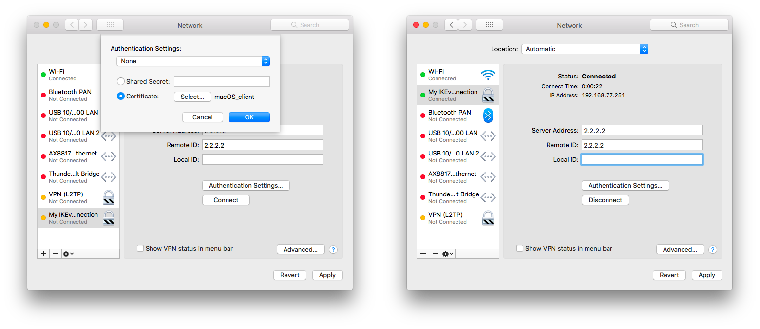
You can now proceed to System Preferences -> Network and add a new configuration by clicking the + button. Select Interface: VPN, VPN Type: IKEv2 and name your connection. Remote ID must be set equal to common-name or subjAltName of server’s certificate. Local ID can be left blank. Under Authentication Settings select None and choose the client certificate. You can now test the connectivity.
Currently, macOS is compatible with the following Phase 1 ( profiles) and Phase 2 ( proposals) proposal sets:
| Phase 1 | ||
|---|---|---|
| Hash Algorithm | Encryption Algorithm | DH Group |
| SHA256 | AES-256-CBC | modp2048 |
| SHA256 | AES-256-CBC | ecp256 |
| SHA256 | AES-256-CBC | modp1536 |
| SHA1 | AES-128-CBC | modp1024 |
| SHA1 | 3DES | modp1024 |
| Phase 2 | ||
|---|---|---|
| Hash Algorithm | Encryption Algorithm | PFS Group |
| SHA256 | AES-256-CBC | none |
| SHA1 | AES-128-CBC | none |
| SHA1 | 3DES | none |
iOS client configuration
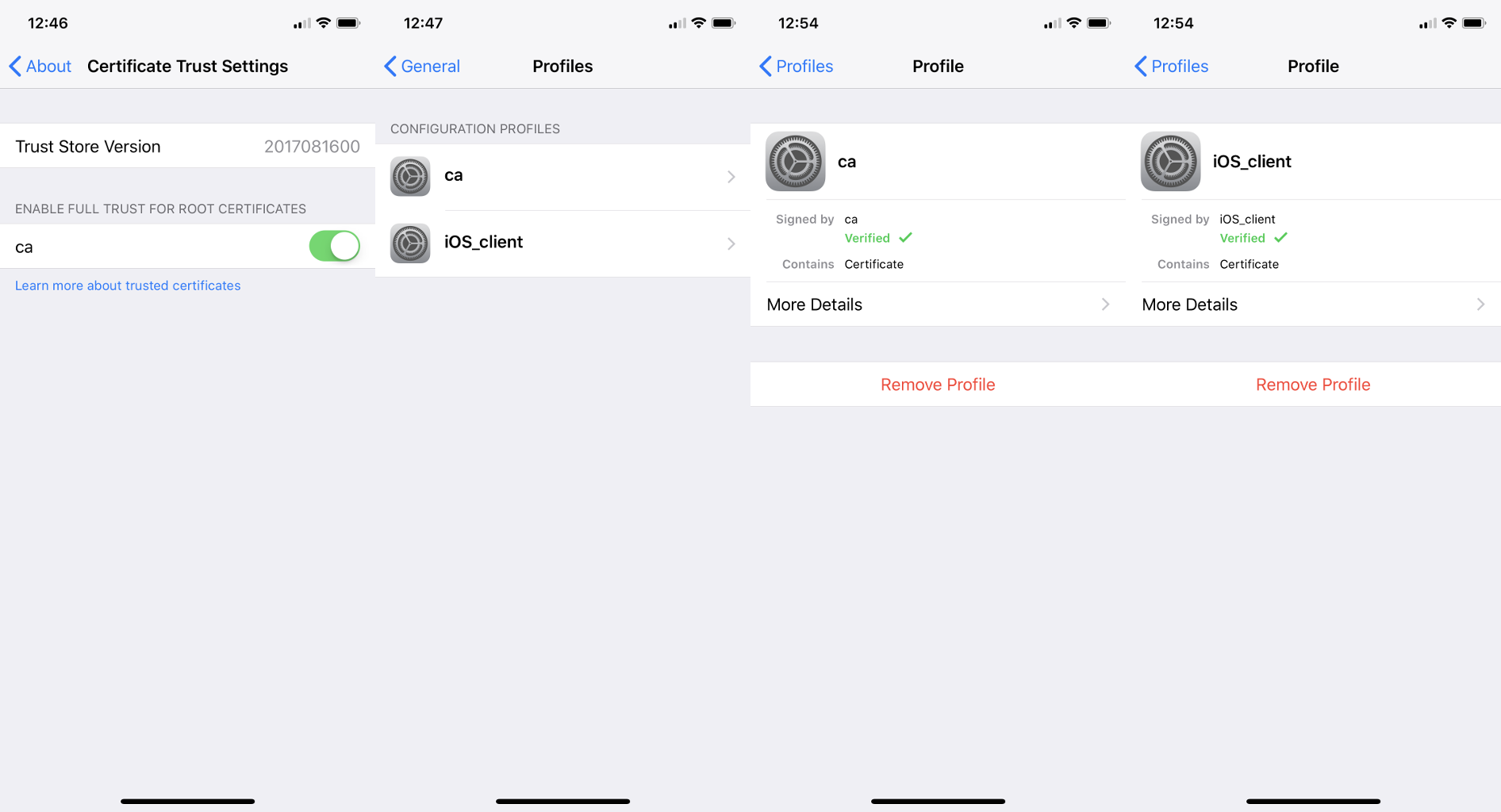
Typically PKCS12 bundle contains also a CA certificate, but iOS does not install this CA, so a self-signed CA certificate must be installed separately using PEM format. Open these files on the iOS device and install both certificates by following the instructions. It is necessary to mark the self-signed CA certificate as trusted on the iOS device. This can be done in Settings -> General -> About -> Certificate Trust Settings menu. When it is done, check whether both certificates are marked as «verified» under the Settings -> General -> Profiles menu.
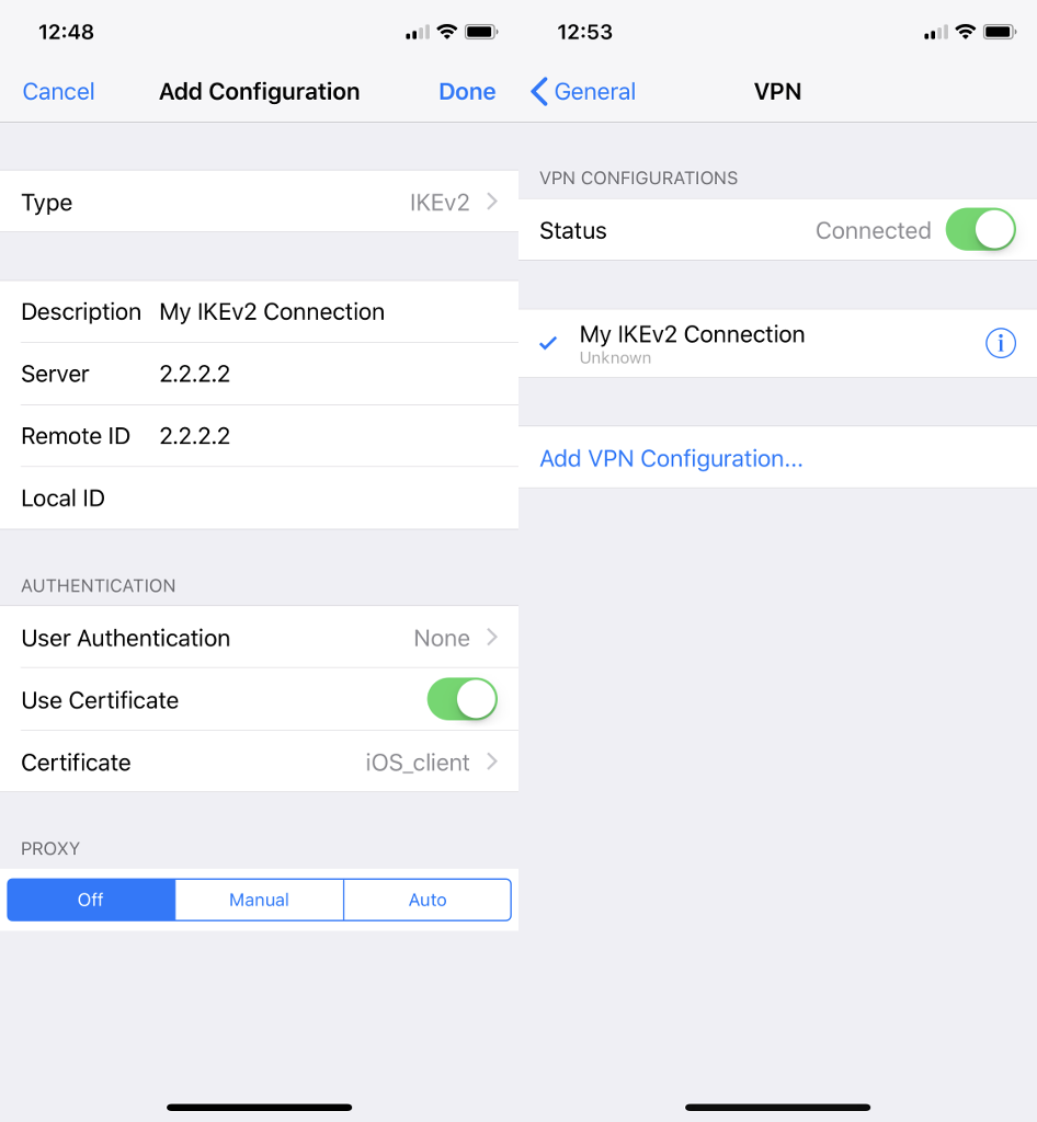
You can now proceed to Settings -> General -> VPN menu and add a new configuration. Remote ID must be set equal to common-name or subjAltName of server’s certificate. Local ID can be left blank.
Currently, iOS is compatible with the following Phase 1 ( profiles) and Phase 2 ( proposals) proposal sets:
| Phase 1 | ||
|---|---|---|
| Hash Algorithm | Encryption Algorithm | DH Group |
| SHA256 | AES-256-CBC | modp2048 |
| SHA256 | AES-256-CBC | ecp256 |
| SHA256 | AES-256-CBC | modp1536 |
| SHA1 | AES-128-CBC | modp1024 |
| SHA1 | 3DES | modp1024 |
| Phase 2 | ||
|---|---|---|
| Hash Algorithm | Encryption Algorithm | PFS Group |
| SHA256 | AES-256-CBC | none |
| SHA1 | AES-128-CBC | none |
| SHA1 | 3DES | none |
If you are connected to the VPN over WiFi, the iOS device can go into sleep mode and disconnect from the network.
Android (strongSwan) client configuration
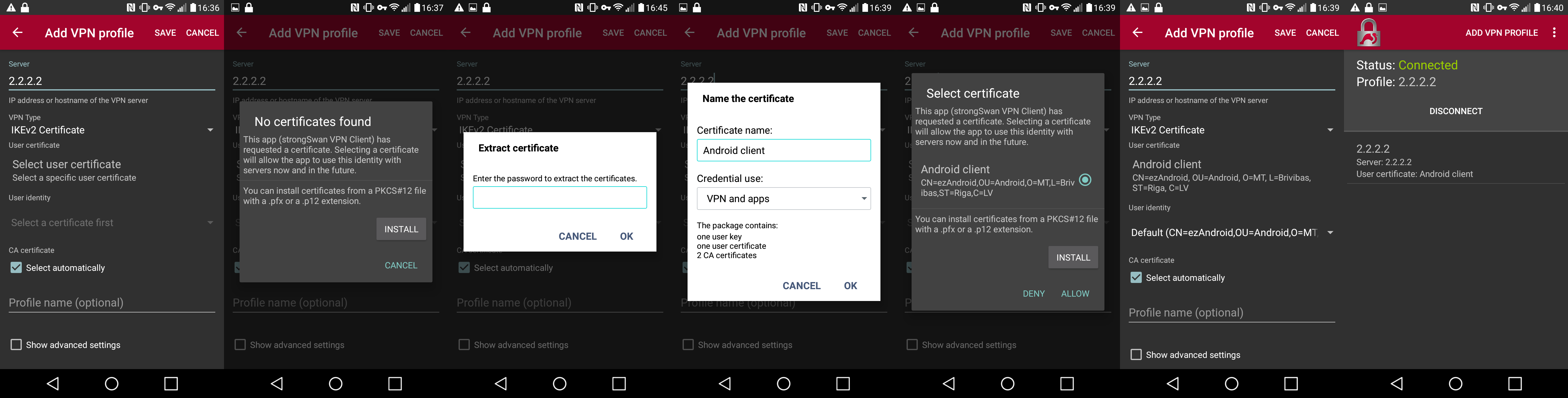
Currently, there is no IKEv2 native support in Android, however, it is possible to use strongSwan from Google Play Store which brings IKEv2 to Android. StrongSwan accepts PKCS12 format certificates, so before setting up the VPN connection in strongSwan, make sure you download the PKCS12 bundle to your Android device. When it is done, create a new VPN profile in strongSwan, type in the server IP, and choose «IKEv2 Certificate» as VPN Type. When selecting a User certificate, press Install and follow the certificate extract procedure by specifying the PKCS12 bundle. Save the profile and test the connection by pressing on the VPN profile.
It is possible to specify custom encryption settings in strongSwan by ticking the «Show advanced settings» checkbox. Currently, strongSwan by default is compatible with the following Phase 1 ( profiles) and Phase 2 ( proposals) proposal sets:
| Phase 1 | ||
|---|---|---|
| Hash Algorithm | Encryption Algorithm | DH Group |
| SHA* | AES-*-CBC | modp2048 |
| SHA* | AES-*-CBC | ecp256 |
| SHA* | AES-*-CBC | ecp384 |
| SHA* | AES-*-CBC | ecp521 |
| SHA* | AES-*-CBC | modp3072 |
| SHA* | AES-*-CBC | modp4096 |
| SHA* | AES-*-CBC | modp6144 |
| SHA* | AES-*-CBC | modp8192 |
| SHA* | AES-*-GCM | modp2048 |
| SHA* | AES-*-GCM | ecp256 |
| SHA* | AES-*-GCM | ecp384 |
| SHA* | AES-*-GCM | ecp521 |
| SHA* | AES-*-GCM | modp3072 |
| SHA* | AES-*-GCM | modp4096 |
| SHA* | AES-*-GCM | modp6144 |
| SHA* | AES-*-GCM | modp8192 |
| Phase 2 | ||
|---|---|---|
| Hash Algorithm | Encryption Algorithm | PFS Group |
| none | AES-256-GCM | none |
| none | AES-128-GCM | none |
| SHA256 | AES-256-CBC | none |
| SHA512 | AES-256-CBC | none |
| SHA1 | AES-256-CBC | none |
| SHA256 | AES-192-CBC | none |
| SHA512 | AES-192-CBC | none |
| SHA1 | AES-192-CBC | none |
| SHA256 | AES-128-CBC | none |
| SHA512 | AES-128-CBC | none |
| SHA1 | AES-128-CBC | none |
Linux (strongSwan) client configuration
Download the PKCS12 certificate bundle and move it to /etc/ipsec.d/private directory.
Add exported passphrase for the private key to /etc/ipsec.secrets file where «strongSwan_client.p12» is the file name and «1234567890» is the passphrase.
: P12 strongSwan_client.p12 "1234567890"
Add a new connection to /etc/ipsec.conf file
conn "ikev2"
keyexchange=ikev2
ike=aes128-sha1-modp2048
esp=aes128-sha1
leftsourceip=%modeconfig
leftcert=strongSwan_client.p12
leftfirewall=yes
right=2.2.2.2
rightid="CN=2.2.2.2"
rightsubnet=0.0.0.0/0
auto=add
You can now restart (or start) the ipsec daemon and initialize the connection
$ ipsec restart
$ ipsec up ikev2
Road Warrior setup using IKEv2 with EAP-MSCHAPv2 authentication handled by User Manager (RouterOS v7)
This example explains how to establish a secure IPsec connection between a device connected to the Internet (road warrior client) and a device running RouterOS acting as an IKEv2 server and User Manager. It is possible to run User Manager on a separate device in network, however in this example both User Manager and IKEv2 server will be configured on the same device (Office).
RouterOS server configuration
Requirements
For this setup to work there are several prerequisites for the router:
- Router’s IP address should have a valid public DNS record — IP Cloud could be used to achieve this.
- Router should be reachable through port TCP/80 over the Internet — if the server is behind NAT, port forwarding should be configured.
- User Manager package should be installed on the router.
Generating Let’s Encrypt certificate
During the EAP-MSCHAPv2 authentication, TLS handshake has to take place, which means the server has to have a certificate that can be validated by the client. To simplify this step, we will use Let’s Encrypt certificate which can be validated by most operating systems without any intervention by the user. To generate the certificate, simply enable SSL certificate under the Certificates menu. By default the command uses the dynamic DNS record provided by IP Cloud, however a custom DNS name can also be specified. Note that, the DNS record should point to the router.
/certificate enable-ssl-certificate
If the certificate generation succeeded, you should see the Let’s Encrypt certificate installed under the Certificates menu.
/certificate print detail where name~"letsencrypt"
Configuring User Manager
First of all, allow receiving RADIUS requests from the localhost (the router itself):
/user-manager router
add address=127.0.0.1 comment=localhost name=local shared-secret=test
Enable the User Manager and specify the Let’s Encrypt certificate (replace the name of the certificate to the one installed on your device) that will be used to authenticate the users.
/user-manager
set certificate="letsencrypt_2021-04-09T07:10:55Z" enabled=yes
Lastly add users and their credentials that clients will use to authenticate to the server.
/user-manager user
add name=user1 password=password
Configuring RADIUS client
For the router to use RADIUS server for user authentication, it is required to add a new RADIUS client that has the same shared secret that we already configured on User Manager.
/radius
add address=127.0.0.1 secret=test service=ipsec
IPsec (IKEv2) server configuration
Add a new Phase 1 profile and Phase 2 proposal entries with pfs-group=none:
/ip ipsec profile
add name=ike2
/ip ipsec proposal
add name=ike2 pfs-group=none
Mode config is used for address distribution from IP/Pools.
/ip pool
add name=ike2-pool ranges=192.168.77.2-192.168.77.254
/ip ipsec mode-config
add address-pool=ike2-pool address-prefix-length=32 name=ike2-conf
Since that the policy template must be adjusted to allow only specific network policies, it is advised to create a separate policy group and template.
/ip ipsec policy group
add name=ike2-policies
/ip ipsec policy
add dst-address=192.168.77.0/24 group=ike2-policies proposal=ike2 src-address=0.0.0.0/0 template=yes
Create a new IPsec peer entry which will listen to all incoming IKEv2 requests.
/ip ipsec peer
add exchange-mode=ike2 name=ike2 passive=yes profile=ike2
Lastly create a new IPsec identity entry that will match all clients trying to authenticate with EAP. Note that generated Let’s Encrypt certificate must be specified.
/ip ipsec identity
add auth-method=eap-radius certificate="letsencrypt_2021-04-09T07:10:55Z" generate-policy=port-strict mode-config=ike2-conf peer=ike2 \
policy-template-group=ike2-policies
(Optional) Split tunnel configuration
Split tunneling is a method that allows road warrior clients to only access a specific secured network and at the same time send the rest of the traffic based on their internal routing table (as opposed to sending all traffic over the tunnel). To configure split tunneling, changes to mode config parameters are needed.
For example, we will allow our road warrior clients to only access the 10.5.8.0/24 network.
/ip ipsec mode-conf
set [find name="rw-conf"] split-include=10.5.8.0/24
It is also possible to send a specific DNS server for the client to use. By default, system-dns=yes is used, which sends DNS servers that are configured on the router itself in IP/DNS. We can force the client to use a different DNS server by using the static-dns parameter.
/ip ipsec mode-conf
set [find name="rw-conf"] system-dns=no static-dns=10.5.8.1
Split networking is not a security measure. The client (initiator) can still request a different Phase 2 traffic selector.
(Optional) Assigning static IP address to user
Static IP address to any user can be assigned by use of RADIUS Framed-IP-Address attribute.
/user-manager user
set [find name="user1"] attributes=Framed-IP-Address:192.168.77.100 shared-users=1
To avoid any conflicts, the static IP address should be excluded from the IP pool of other users, as well as shared-users should be set to 1 for the specific user.
(Optional) Accounting configuration
To keep track of every user’s uptime, download and upload statistics, RADIUS accounting can be used. By default RADIUS accounting is already enabled for IPsec, but it is advised to configure Interim Update timer that sends statistic to the RADIUS server regularly. If the router will handle a lot of simultaneous sessions, it is advised to increase the update timer to avoid increased CPU usage.
/ip ipsec settings
set interim-update=1m
Basic L2TP/IPsec setup
This example demonstrates how to easily set up an L2TP/IPsec server on RouterOS for road warrior connections (works with Windows, Android, iOS, macOS, and other vendor L2TP/IPsec implementations).
RouterOS server configuration
The first step is to enable the L2TP server:
/interface l2tp-server server
set enabled=yes use-ipsec=required ipsec-secret=mySecret default-profile=default
use-ipsec is set to required to make sure that only IPsec encapsulated L2TP connections are accepted.
Now what it does is enables an L2TP server and creates a dynamic IPsec peer with a specified secret.
[admin@MikroTik] /ip ipsec peer> print
0 D address=0.0.0.0/0 local-address=0.0.0.0 passive=yes port=500
auth-method=pre-shared-key secret="123" generate-policy=port-strict
exchange-mode=main-l2tp send-initial-contact=yes nat-traversal=yes
hash-algorithm=sha1 enc-algorithm=3des,aes-128,aes-192,aes-256
dh-group=modp1024 lifetime=1d dpd-interval=2m dpd-maximum-failures=5
Care must be taken if static IPsec peer configuration exists.
The next step is to create a VPN pool and add some users.
/ip pool add name=vpn-pool range=192.168.99.2-192.168.99.100

/ppp profile
set default local-address=192.168.99.1 remote-address=vpn-pool

/ppp secret
add name=user1 password=123
add name=user2 password=234
Now the router is ready to accept L2TP/IPsec client connections.
RouterOS client configuration
For RouterOS to work as L2TP/IPsec client, it is as simple as adding a new L2TP client.
/interface l2tp-client
add connect-to=1.1.1.1 disabled=no ipsec-secret=mySecret name=l2tp-out1 \
password=123 use-ipsec=yes user=user1
It will automatically create dynamic IPsec peer and policy configurations.
Troubleshooting/FAQ
Phase 1 Failed to get a valid proposal
[admin@MikroTik] /log> print
(..)
17:12:32 ipsec,error no suitable proposal found.
17:12:32 ipsec,error 10.5.107.112 failed to get valid proposal.
17:12:32 ipsec,error 10.5.107.112 failed to pre-process ph1 packet (side: 1, status 1).
17:12:32 ipsec,error 10.5.107.112 phase1 negotiation failed.
(..)
Peers are unable to negotiate encryption parameters causing the connection to drop. To solve this issue, enable IPSec to debug logs and find out which parameters are proposed by the remote peer, and adjust the configuration accordingly.
[admin@MikroTik] /system logging> add topics=ipsec,!debug
[admin@MikroTik] /log> print
(..)
17:21:08 ipsec rejected hashtype: DB(prop#1:trns#1):Peer(prop#1:trns#1) = MD5:SHA
17:21:08 ipsec rejected enctype: DB(prop#1:trns#2):Peer(prop#1:trns#1) = 3DES-CBC:AES-CBC
17:21:08 ipsec rejected hashtype: DB(prop#1:trns#2):Peer(prop#1:trns#1) = MD5:SHA
17:21:08 ipsec rejected enctype: DB(prop#1:trns#1):Peer(prop#1:trns#2) = AES-CBC:3DES-CBC
17:21:08 ipsec rejected hashtype: DB(prop#1:trns#1):Peer(prop#1:trns#2) = MD5:SHA
17:21:08 ipsec rejected hashtype: DB(prop#1:trns#2):Peer(prop#1:trns#2) = MD5:SHA
17:21:08 ipsec,error no suitable proposal found.
17:21:08 ipsec,error 10.5.107.112 failed to get valid proposal.
17:21:08 ipsec,error 10.5.107.112 failed to pre-process ph1 packet (side: 1, status 1).
17:21:08 ipsec,error 10.5.107.112 phase1 negotiation failed.
(..)
In this example, the remote end requires SHA1 to be used as a hash algorithm, but MD5 is configured on the local router. Setting before the column symbol (:) is configured on the local side, parameter after the column symbol (:) is configured on the remote side.
«phase1 negotiation failed due to time up» what does it mean?
There are communication problems between the peers. Possible causes include — misconfigured Phase 1 IP addresses; firewall blocking UDP ports 500 and 4500; NAT between peers not properly translating IPsec negotiation packets. This error message can also appear when a local-address parameter is not used properly. More information available here.
Random packet drops or connections over the tunnel are very slow, enabling packet sniffer/torch fixes the problem?
Problem is that before encapsulation packets are sent to Fasttrack/FastPath, thus bypassing IPsec policy checking. The solution is to exclude traffic that needs to be encapsulated/decapsulated from Fasttrack, see configuration example here.
How to enable ike2?
For basic configuration enabling ike2 is very simple, just change exchange-mode in peer settings to ike2.
fatal NO-PROPOSAL-CHOSEN notify message?
Remote peer sent notify that it cannot accept proposed algorithms, to find the exact cause of the problem, look at remote peers debug logs or configuration and verify that both client and server have the same set of algorithms.
I can ping only in one direction?
A typical problem in such cases is strict firewall, firewall rules allow the creation of new connections only in one direction. The solution is to recheck firewall rules, or explicitly accept all traffic that should be encapsulated/decapsulated.
Can I allow only encrypted traffic?
Yes, you can, see «Allow only IPsec encapsulated traffic» examples.
I enable IKEv2 REAUTH on StrongSwan and got the error ‘initiator did not reauthenticate as requested’
RouterOS does not support rfc4478, reauth must be disabled on StrongSwan.
Contents
Introduction
In this sample configuration, a remote router receives an IP address through part of PPP called IP Control Protocol (IPCP). The remote router uses the IP address to connect to a hub router. This configuration enables the hub router to accept dynamic IPSec connections. The remote router uses network address translation (NAT) to «join» the privately addressed devices behind it to the privately addressed network behind the hub router. The remote router knows the endpoint and can initiate connections to the hub router. But the hub router does not know the endpoint, so it cannot initiate connections to the remote router.
In this example, dr_whoovie is the remote router and sam-i-am is the hub router. An access list specifies what traffic is to be encrypted, so dr_whoovie knows what traffic to encrypt and where the sam-i-am endpoint is located. The remote router must initiate the connection. Both sides are doing NAT overload.
Prerequisites
Requirements
This document requires a basic understanding of IPSec protocol. To learn more about IPSec, please refer to An Introduction to IP Security (IPSec) Encryption.
Components Used
The information in this document is based on these software and hardware versions:
-
Cisco IOS® Software Release 12.2(24a)
-
Cisco 2500 Series Routers
The information in this document was created from the devices in a specific lab environment. All of the devices used in this document started with a cleared (default) configuration. If your network is live, make sure that you understand the potential impact of any command.
Conventions
Refer to Cisco Technical Tips Conventions for more information on document conventions.
Configure
In this section, you are presented with the information to configure the features described in this document.
Note: Use the Command Lookup Tool (registered customers only) to find more information on the commands used in this document.
Network Diagram
This document uses this network setup:
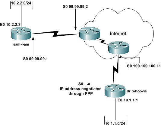
Configurations
This document uses these configurations:
-
sam-i-am
-
dr_whoovie
| sam-i-am |
|---|
Current configuration: ! version 12.2 service timestamps debug uptime service timestamps log up time no service password-encryption ! hostname sam-i-am ! ip subnet-zero ! !--- These are the IKE policies. crypto isakmp policy 1 !--- Defines an Internet Key Exchange (IKE) policy. !--- Use the crypto isakmp policy command !--- in global configuration mode. !--- IKE policies define a set of parameters to be used !--- during the IKE phase I negotiation. hash md5 authentication pre-share !--- Specifies pre-shared keys as the authentication method. crypto isakmp key cisco123 address 0.0.0.0 0.0.0.0 !--- Configures a pre-shared authentication key, !--- used in global configuration mode. ! !--- These are the IPSec policies. crypto ipsec transform-set rtpset esp-des esp-md5-hmac !--- A transform set is an acceptable combination !--- of security protocols and algorithms. !--- This command defines a transform set !--- that has to be matched on the peer router. crypto dynamic-map rtpmap 10 !--- Use dynamic crypto maps to create policy templates !--- that can be used to process negotiation requests !--- for new security associations (SA) from a remote IPSec peer, !--- even if you do not know all of the crypto map parameters !--- required to communicate with the remote peer, !--- such as the IP address of the peer. set transform-set rtpset !--- Configure IPSec to use the transform set "rtpset" !--- that was defined previously. match address 115 !--- Assign an extended access list to a crypto map entry !--- that is used by IPSec to determine which traffic !--- should be protected by crypto and which traffic !--- does not need crypto protection. crypto map rtptrans 10 ipsec-isakmp dynamic rtpmap !--- Specifies that this crypto map entry is to reference !--- a preexisting dynamic crypto map. ! interface Ethernet0 ip address 10.2.2.3 255.255.255.0 no ip directed-broadcast ip nat inside !--- This indicates that the interface is connected to the !--- inside network, which is subject to NAT translation. no mop enabled ! interface Serial0 ip address 99.99.99.1 255.255.255.0 no ip directed-broadcast ip nat outside !--- This indicates that the interface is connected !--- to the outside network. crypto map rtptrans !--- Use the crypto map interface configuration command !--- to apply a previously defined crypto map set to an interface. ! ip nat inside source route-map nonat interface Serial0 overload !--- Except the private network from the NAT process. ip classless ip route 0.0.0.0 0.0.0.0 Serial0 no ip http server ! access-list 115 permit ip 10.2.2.0 0.0.0.255 10.1.1.0 0.0.0.255 access-list 115 deny ip 10.2.2.0 0.0.0.255 any !--- Include the private-network-to-private-network traffic !--- in the encryption process. access-list 120 deny ip 10.2.2.0 0.0.0.255 10.1.1.0 0.0.0.255 access-list 120 permit ip 10.2.2.0 0.0.0.255 any !--- Except the private network from the NAT process. route-map nonat permit 10 match ip address 120 ! line con 0 transport input none line aux 0 line vty 0 4 password ww login ! end |
| dr_whoovie |
|---|
Current configuration: ! version 12.2 service timestamps debug uptime service timestamps log uptime no service password-encryption ! hostname dr_whoovie ! ip subnet-zero ! !--- These are the IKE policies. crypto isakmp policy 1 !--- Defines an Internet Key Exchange (IKE) policy. !--- Use the crypto isakmp policy command !--- in global configuration mode. !--- IKE policies define a set of parameters to be used !--- during the IKE phase I negotiation. hash md5 authentication pre-share !--- Specifies pre-shared keys as the authentication method. crypto isakmp key cisco123 address 99.99.99.1 !--- Configures a pre-shared authentication key, !--- used in global configuration mode. ! !--- These are the IPSec policies. crypto ipsec transform-set rtpset esp-des esp-md5-hmac !--- A transform set is an acceptable combination !--- of security protocols and algorithms. !--- This command defines a transform set !--- that has to be matched on the peer router. ! crypto map rtp 1 ipsec-isakmp !--- Creates a crypto map and indicates that IKE will be used !--- to establish the IPSec SAs for protecting !--- the traffic specified by this crypto map entry. set peer 99.99.99.1 !--- Use the set peer command to specify an IPSec peer in a crypto map entry. set transform-set rtpset !--- Configure IPSec to use the transform set "rtpset" !--- that was defined previously. match address 115 !--- Include the private-network-to-private-network traffic !--- in the encryption process. ! interface Ethernet0 ip address 10.1.1.1 255.255.255.0 no ip directed-broadcast ip nat inside !--- This indicates that the interface is connected to the !--- inside network, which is subject to NAT translation. no mop enabled ! interface Serial0 ip address negotiated !--- Specifies that the IP address for this interface !--- is obtained via PPP/IPCP address negotiation. !--- This example was set up in a lab with an IP address !--- assigned with IPCP. no ip directed-broadcast ip nat outside !--- This indicates that the interface is connected !--- to the outside network. encapsulation ppp no ip mroute-cache no ip route-cache crypto map rtp !--- Use the crypto map interface configuration command !--- to apply a previously defined crypto map set to an interface. ip nat inside source route-map nonat interface Serial0 overload !--- Except the private network from the NAT process. ip classless ip route 0.0.0.0 0.0.0.0 Serial0 no ip http server ! access-list 115 permit ip 10.1.1.0 0.0.0.255 10.2.2.0 0.0.0.255 access-list 115 deny ip 10.1.1.0 0.0.0.255 any !--- Include the private-network-to-private-network traffic !--- in the encryption process. access-list 120 deny ip 10.1.1.0 0.0.0.255 10.2.2.0 0.0.0.255 access-list 120 permit ip 10.1.1.0 0.0.0.255 any !--- Except the private network from the NAT process. dialer-list 1 protocol ip permit dialer-list 1 protocol ipx permit route-map nonat permit 10 match ip address 120 ! line con 0 transport input none line aux 0 line vty 0 4 password ww login ! end |
Verify
This section provides information you can use to confirm your configuration is working properly.
Certain show commands are supported by the Output Interpreter Tool (registered customers only) , which allows you to view an analysis of show command output.
-
ping —Used to diagnose basic network connectivity
This example shows a ping from the 10.1.1.1 Ethernet interface on dr_whoovie to the 10.2.2.3 Ethernet interface on sam-i-am.
dr_whoovie# ping
Protocol [ip]:
Target IP address: 10.2.2.3
Repeat count [5]:
Datagram size [100]:
Timeout in seconds [2]:
Extended commands [n]: y
Source address or interface: 10.1.1.1
Type of service [0]:
Set DF bit in IP header? [no]:
Validate reply data? [no]:
Data pattern [0xABCD]:
Loose, Strict, Record, Timestamp, Verbose[none]:
Sweep range of sizes [n]:
Type escape sequence to abort.
Sending 5, 100-byte ICMP Echos to 10.2.2.3,
  timeout is 2 seconds:
Packet sent with a source address of 10.1.1.1
!!!!!
Success rate is 100 percent (5/5),
  round-trip min/avg/max = 36/38/40 ms
-
show crypto ipsec sa —Shows the phase 2 security associations (SA).
-
show crypto isakmp sa —Shows the phase 1 SAs.
Sample Output
This output is from the show crypto ipsec sa command issued on the hub router.
sam-i-am# show crypto ipsec sa

interface: Serial0
    Crypto map tag: rtptrans, local addr. 99.99.99.1

   local  ident (addr/mask/prot/port): (10.2.2.0/255.255.255.0/0/0)
   remote ident (addr/mask/prot/port): (10.1.1.0/255.255.255.0/0/0)
   current_peer: 100.100.100.1
     PERMIT, flags={}
    #pkts encaps: 6, #pkts encrypt: 6, #pkts digest 6
    #pkts decaps: 6, #pkts decrypt: 6, #pkts verify 6
    #pkts compressed: 0, #pkts decompressed: 0
    #pkts not compressed: 0, #pkts compr. failed: 0,
    #pkts decompress failed: 0, #send errors 0, #recv errors 0

     local crypto endpt.: 99.99.99.1, remote crypto endpt.: 100.100.100.1
     path mtu 1500, ip mtu 1500, ip mtu interface Serial0
     current outbound spi: 52456533

     inbound esp sas:
      spi: 0x6462305C(1684156508)
        transform: esp-des esp-md5-hmac ,
        in use settings ={Tunnel, }
        slot: 0, conn id: 2000, flow_id: 1, crypto map: rtptrans
        sa timing: remaining key lifetime (k/sec): (4607999/3510)
        IV size: 8 bytes
        replay detection support: Y

     inbound ah sas:

     inbound pcp sas:

     outbound esp sas:
      spi: 0x52456533(1380279603)
        transform: esp-des esp-md5-hmac ,
        in use settings ={Tunnel, }
        slot: 0, conn id: 2001, flow_id: 2, crypto map: rtptrans
        sa timing: remaining key lifetime (k/sec): (4607999/3510)
        IV size: 8 bytes
        replay detection support: Y

     outbound ah sas:

     outbound pcp sas:
This command shows IPSec SAs that are built between the peer devices. The encrypted tunnel connects the 100.100.100.1 interface on dr_whoovie and the 99.99.99.1 interface on sam-i-am. This tunnel carries traffic going between networks 10.2.2.3 and 10.1.1.1. Two Encapsulating Security Payload (ESP) SAs are built inbound and outbound. The tunnel is established even though sam-i-am does not know the peer IP address (100.100.100.1). Authentication Header (AH) SAs are not used since there are no AH configured.
These outputs samples show that the serial interface 0 on dr_whoovie receives an IP address of 100.100.100.1 through IPCP.
-
Before the IP address is negotiated:
dr_whoovie#show interface serial0 Serial0 is up, line protocol is up Hardware is HD64570 Internet address will be negotiated using IPCP MTU 1500 bytes, BW 1544 Kbit, DLY 20000 usec, reliability 255/255, txload 1/255, rxload 1/255 Encapsulation PPP, loopback not set -
After the IP address is negotiated:
dr_whoovie#show interface serial0
Serial0 is up, line protocol is up
  Hardware is HD64570
  Internet address is 100.100.100.1/32
  MTU 1500 bytes, BW 1544 Kbit, DLY 20000 usec,
     reliability 255/255, txload 1/255, rxload 1/255
  Encapsulation PPP, loopback not set
This example was set up in a lab with the peer default ip address command to assign an IP address at the remote end of the serial 0 interface on dr_whoovie. The IP pool is defined with the ip local pool command at the remote end.
Troubleshoot
This section provides information you can use to troubleshoot your configuration.
Troubleshooting Commands
The Output Interpreter Tool (registered customers only) (OIT) supports certain show commands. Use the OIT to view an analysis of show command output.
Note: Refer to Important Information on Debug Commands before you use debug commands.
-
debug crypto ipsec —Shows the IPSec negotiations of phase 2.
-
debug crypto isakmp —Shows the Internet Security Association and Key Management Protocol (ISAKMP) negotiations of phase 1.
-
debug crypto engine —Shows the traffic that is encrypted.
-
debug ip nat detailed —(Optional) Verifies the operation of the NAT feature by displaying information about every packet that the router translates.
 Caution: This command generates a large amount of output. Use this command only when traffic on the IP network is low.
 -
clear crypto isakmp —Clears the SAs related to phase 1.
-
clear crypto sa —Clears the SAs related to phase 2.
-
clear ip nat translation —Clears dynamic NAT translations from the translation table.
 Caution: This command generates a large amount of output. Use this command only when traffic on the IP network is low.
 Related Information
- IPSec Support Page
- Technical Support — Cisco Systems
 Задача объединения нескольких сетей в разных офисах одна из наиболее часто встречающихся у системных администраторов. Для ее решения могут использоваться различные виды VPN и туннельных соединений, выбор которых может зависеть от множества требований и условий. Одной из альтернатив туннелям и VPN может служить «чистое» IPsec-соединение, которое имеет как свои достоинства, так и недостатки. В данном материале мы рассмотрим реализацию подобного соединения между сетями офисов (site-to-site) c использованием оборудования Mikrotik.
Научиться настраивать MikroTik с нуля или систематизировать уже имеющиеся знания можно на углубленном курсе по администрированию MikroTik. Автор курса, сертифицированный тренер MikroTik Дмитрий Скоромнов, лично проверяет лабораторные работы и контролирует прогресс каждого своего студента. В три раза больше информации, чем в вендорской программе MTCNA, более 20 часов практики и доступ навсегда.
IPsec — набор протоколов для обеспечения защиты данных, передаваемых в сетях по протоколу IP. Основным преимуществом IPsec является высокий уровень безопасности, на сегодняшний день он является лучшим протоколом для защиты передаваемых данных. Также следует отметить высокий уровень производительности, при условии достаточного количества вычислительных ресурсов для работы с криптографией. Применительно к устройствам Mikrotik IPsec позволяет получить одни из самых высоких результатов, особенно на устройствах с аппаратной поддержкой шифрования.
Но есть и недостатки, они тоже достаточно существенны. IPsec сложен, как в настройке, так в понимании его работы, это требует от администратора более глубокого уровня знаний и может вызвать серьезные затруднения при отладке и диагностике неисправностей. Также IPsec не использует интерфейсы, а обрабатывает трафик на основании собственных политик, это также приводит к ряду затруднений, начиная от прохождения трафика через брандмауэр и заканчивая невозможностью применения маршрутизации для таких соединений. Часть сетевых конфигураций легко реализуемых при помощи VPN и туннелей построить при помощи IPsec в принципе невозможно.
Далее мы рассмотрим объединение двух офисных сетей по представленной ниже схеме:
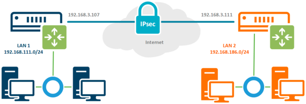 Где LAN 1 с диапазоном 192.168.111.0/24 и LAN 2 — 192.168.186.0/24 — это сети двух офисов, которые мы будем объединять, а 192.168.3.107 и 192.168.3.111 — выполняют роль внешних белых адресов в сети интернет. Наша задача обеспечить прозрачный доступ устройств одной сети в другую через защищенный канал связи.
Настройка IPsec соединения
Соединение IPsec имеет отличия как от предусматривающего клиент-серверную схему VPN, так и от stateless туннелей. В отличие от последних мы всегда можем проверить состояние соединения, но понятие клиента и сервера здесь отсутствует, в IPsec одно из устройств выступает в качестве инициатора (initiator), а второе в качестве ответчика (responder). Эти роли не являются жестко закрепленными и могут меняться между устройствами, хотя при необходимости мы можем закрепить за определенным устройством постоянную роль.
Например, это позволяет установить IPsec соединение, когда один из узлов не имеет выделенного IP-адреса, в этом случае ему следует настроить роль инициатора, а второму узлу роль ответчика. В нашем случае подразумевается наличие выделенных адресов с обоих сторон и каждое из устройств может выступать в любой роли.
Настройку начнем с определения алгоритмов шифрования для каждой фазы соединения. Так как мы соединяем два собственных устройства, то можем не оглядываться на требования совместимости и настроить параметры шифрования на собственное усмотрение. Но без фанатизма, не забываем, что многие устройства Mikrotik достаточно слабые и не имеют аппаратной поддержки шифрования, а те, которые имеют, поддерживают различный набор протоколов.
Так популярный RB750Gr3 (hEX) поддерживает аппаратное ускорение только SHA1/SHA256 — AES-CBC, а более новый RB3011 уже поддерживает SHA1/SHA256 — AES-CBC и SHA1/SHA256 — AES-CTR. Желание использовать сильные шифры безусловно похвально, но оно не должно опережать возможности имеющегося оборудования.
Первая фаза — обмен ключами и взаимная идентификация устройств, за ее настройки отвечает раздел IP — IPsec — Profiles, перейдем в него и создадим новый профиль. Для него укажем: Hash Algorithms — sha1, Encryption Algorithm — aes-256, DH Group — ecp384. В поле Name укажем имя профиля, в нашем случае ipsec-sts (site-to-site).
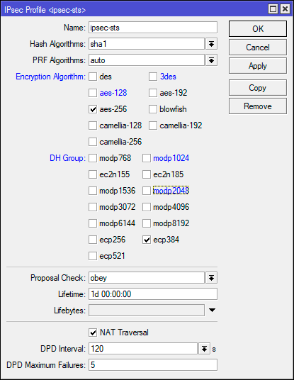 В терминале для выполнения этого же действия выполните:
/ip ipsec profile
add dh-group=ecp384 enc-algorithm=aes-256 name=ipsec-sts
Это достаточно сильные настройки шифров, для устройств без аппаратного ускорения мы бы посоветовали ограничиться aes-128 и modp1024, хотя никто не мешает протестировать желаемые варианты и остановиться на наиболее оптимальном.
Вторая фаза — установление защищённого соединения и передача данных, настройки шифров для нее задаются в IP — IPsec — Proposal, перейдем в данный раздел и создадим новое предложение. Укажем Auth. Algorithms — sha1, Encr. Algorithms — aes-256-cbc, PFS Group — ecp384.
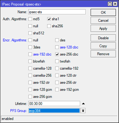 Это же действие в терминале:
/ip ipsec proposal
add enc-algorithms=aes-256-cbc name=ipsec-sts pfs-group=ecp384
В данном примере мы использовали не самые сильные шифры, так режим шифрования CBC является наиболее слабым и при наличии аппаратной поддержки стоит использовать CTR или GCM. Но не забывайте о достаточной разумности, если нагрузка на устройство велика — понижайте уровень шифрования.
Теперь перейдем в IP — IPsec — Peer и создадим новое подключение. В поле Address указываем внешний адрес второго роутера, в Profile выбираем созданный нами на предыдущем этапе профиль, в нашем случае ipsec-sts, а в поле Exchange Mode указываем IKE2.
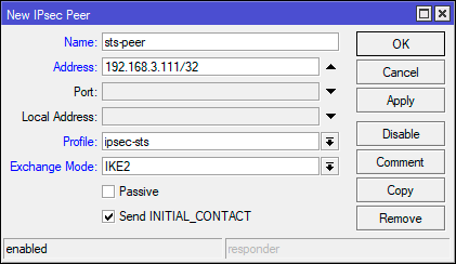 В терминале:
/ip ipsec peer
add address=192.168.3.111/32 exchange-mode=ike2 name=sts-peer profile=ipsec-sts
В целом того, что мы уже настроили достаточно для установления защищенного соединения, но IPsec не VPN и работает по-другому. Для того, чтобы трафик начал шифроваться он должен соответствовать одной из политик IPsec, поэтому перейдем в IP — IPsec — Policies и создадим новую политику. В поле Peer укажем созданное ранее соединение, ниже установим флаг Tunnel для работы соединения в туннельном режиме, в поле Src. Address укажем диапазон собственной сети — 192.168.111.0/24, а в поле Dst. Address — диапазон удаленной сети — 192.168.186.0/24.
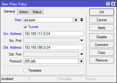
Затем на закладке Action установите Proposal — ipsec-sts, предложение которое мы создали ранее.
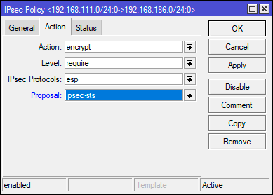
Для терминала используйте следующие команды:
/ip ipsec policy
add dst-address=192.168.186.0/24 peer=sts-peer proposal=ipsec-sts src-address=192.168.111.0/24 tunnel=yes
Ну и осталось совсем немного — научить узлы идентифицировать друг друга, так как оба роутера контролируются администратором и настроены принимать подключения только от другого узла, то мы будем использовать аутентификацию по предварительному ключу. Перейдем в IP — IPsec — Identities и создадим новую настройку идентификации. Здесь нам нужно заполнить поля: Peer — указываем созданное нами соединение, в нашем случае ipsec-sts, Auth. Method — pre shared key, Secret — предварительный ключ. В качестве предварительного ключа рекомендуется использовать строку с использованием цифр, букв в разных регистрах и специальных символов, сформированных в случайном порядке и с длинной не менее 16-32 символов. Не следует использовать в качестве ключа словарные слова и фразы. Предупреждения внизу окна можно проигнорировать.
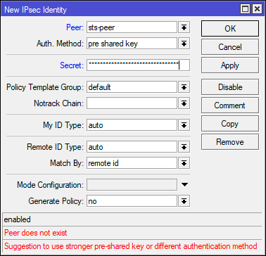 В терминале:
/ip ipsec identity
add peer=sts-peer secret="2KuSY2%QKt\$\$gs8V9nrERD@V8zAuh\$3S"
На втором узле следует выполнить аналогичные настройки, только в качестве адреса в Peer указав внешний адрес первого роутера, а в Policy поменяв местами сеть источника и сеть назначения.
Настройка брандмауэра
Будем считать, что вы используете нормально закрытый брандмауэр настроенный в соответствии с нашими рекомендациями. Для того, чтобы разрешить входящее IPsec-соединение перейдем в IP — Firewall — Filter Rules и добавим следующие правила. Первое из них разрешает работу протокола обмена ключами IKE: Chain — input, Protocol — udp, Dst. Port — 500,4500, In. Interface — внешний интерфейс, в нашем случае ether1.
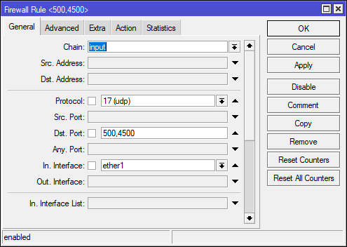 Второе правило разрешает протокол шифрования полезной нагрузки Encapsulating Security Payload (ESP): Chain — input, Protocol — 50 (ipsec-esp), In. Interface — внешний интерфейс — ether1.
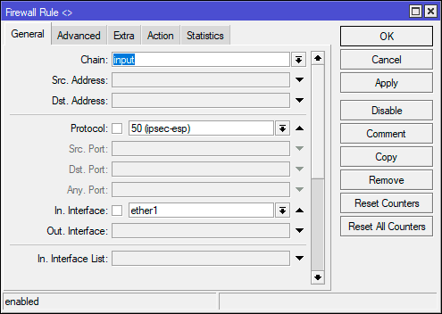
Обратите внимание, что мы нигде не указываем действие, потому что по умолчанию все правила имеют в качестве действия accept — разрешить.
Эти же действия можно быстро выполнить в терминале:
/ip firewall filter
add action=accept chain=input dst-port=500,4500 in-interface=ether1 protocol=udp
add action=accept chain=input in-interface=ether1 protocol=ipsec-esp
Для того, чтобы пакеты из одной сети могли попасть в другую, следует разрешить их транзит. Создадим еще одно правило: Chain — forward, In. Interface — внешний интерфейс — ether1, затем на закладке Advanced укажем IPsec Policy — in:ipsec. Это разрешит транзит любых входящих пакетов, которые попадают под любую установленную политику IPsec.
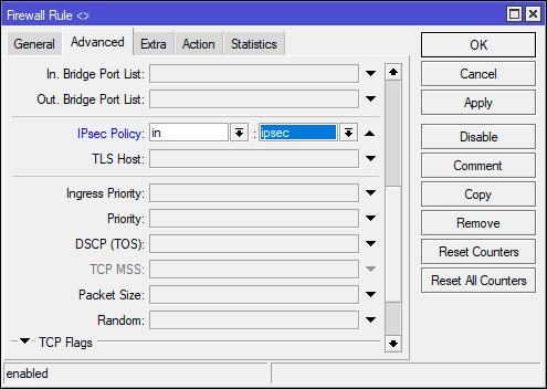 В терминале:
/ip firewall filter
add action=accept chain=forward in-interface=ether1 ipsec-policy=in,ipsec
Аналогичные настройки следует выполнить на втором узле.
Обход NAT и Fasttrack
Как мы уже говорили, IPsec не использует интерфейсы, а следовательно, обрабатываемый им трафик, хоть и уходит в защищенный туннель, но продолжает использовать в качестве исходящего внешний интерфейс, что может привести к ряду коллизий. Прежде всего нужно исключить обработку такого трафика правилами snat или masquerade. Для этого перейдем в IP — Firewall — NAT и создадим новое правило: Chain — srcnat, Src. Address — 192.168.111.0/24 — диапазон локальной сети, Dst. Address — 192.168.186.0/24 — диапазон удаленной сети, так как действие по умолчанию accept, то явно его не указываем. Данное правило поднимаем в самый верх, одно должно быть первым в цепочке srcnat.
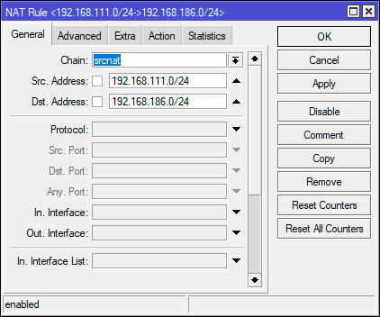 Через терминал добавить его можно следующей командой:
/ip firewall nat
add action=accept chain=srcnat dst-address=192.168.186.0/24 src-address=192.168.111.0/24 place-before=0
Опция place-before=0 позволяет поставить правило в самое начало цепочки.
Если вы используете Fasttrack, то также следует исключить обработку проходящего через IPsec трафика этим механизмом, для этого следует добавить два правила. Первое для трафика из локальной сети в удаленную: Chain — forward, Src. Address — 192.168.111.0/24 — диапазон локальной сети, Dst. Address — 192.168.186.0/24 — диапазон удаленной сети, Сonnection State — established, related.
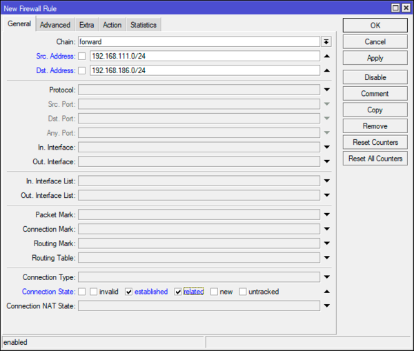 Второе правило для трафика из удаленной сети в локальную, оно полностью повторяет первое, только меняем местами сеть источника (Src. Address) и сеть назначения (Dst. Address).
В терминале:
/ip firewall filter
add chain=forward action=accept place-before=0 src-address=192.168.111.0/24 dst-address=192.168.186.0/24 connection-state=established,related
add chain=forward action=accept place-before=0 src-address=192.168.186.0/24 dst-address=192.168.111.0/24 connection-state=established,related
Аналогичные настройки, с учетом адресов, следует выполнить и на втором узле.
Заключение
После того, как мы завершили процесс настройки перейдем в IP — IPsec — Active Peers и убедимся, что соединение между двумя узлами установлено. Если это не так — еще раз проверяем все настройки и изучаем файл лога, скорее всего у вас не совпадают параметры шифрования или идентификации.
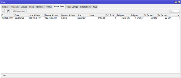 Теперь откроем IP — IPsec — Installed SAs. В терминах IPsec — SA (Security Association) — ассоциация безопасности, обозначает установленное защищенное соединение. Для каждого соединения создается отдельная пара SA, так как каждая SA — это однонаправленное соединение, а данные нужно передавать по двум направлениям. Если запустить обмен данными между сетями, скажем пропинговать с узла одной сети узел другой сети, то мы увидим, что данные счетчика Current Bytes начинают меняться, а следовательно, шифрование работает и данные передаются внутри защищенного соединения.
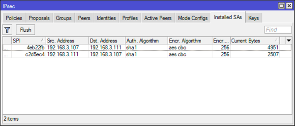 Как видим, если хотя бы на базовом уровне понимать принципы действия IPsec, то настроить туннель между двумя сетями относительно несложно. Надеемся, что данный материал будет вам полезен.
Научиться настраивать MikroTik с нуля или систематизировать уже имеющиеся знания можно на углубленном курсе по администрированию MikroTik. Автор курса, сертифицированный тренер MikroTik Дмитрий Скоромнов, лично проверяет лабораторные работы и контролирует прогресс каждого своего студента. В три раза больше информации, чем в вендорской программе MTCNA, более 20 часов практики и доступ навсегда.
Используя функцию LAN-to-LAN IPsec VPN две различные частные сети могут быть подключены друг к другу через интернет. К примеру, возьмем приведенную на рисунке ниже топологию. Следуя инструкции ниже, вы сможете настроить похожее VPN соединение.
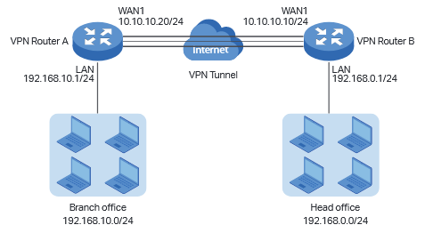
Внимание!
В данном примере WAN IP адреса обоих роутеров «серые», но при этом мы допускаем, что они находятся в одной подсети, например, подсети провайдера. Если два ваших устройства находятся в разных подсетях, для настройки IPsec VPN вам потребуются «белые» IP адреса на обоих маршрутизаторах (услуга приобретается у вашего интернет-провайдера)
Шаг 1. Проверяем настройки, которые нужны для настройки IPsec VPN на роутерах.
Проверим VPN на роутере А
Перейдите в раздел Status > System Status

В разделе Network > LAN

Затем проверьте те же настройки на роутере В.
В разделе Status > System Status

Network > LAN

Шаг 2 Настройка IPsec VPN на роутере В
- Перейдите в меню VPN > IPSec > IPSec Policy и нажмите Add чтобы открыть страницу со скриншота нароутере. Настройте базовые параметры для политики IPseс.
- Поставьте режим
- Remote Gateway — 10.10.10.20
- WAN – WAN1
- Local subnet 192.168.0.0/24
- Remote subnet 192.168.10.0/24
- Pre-shared key –любой пароль по вашему выбору. В качестве примера – 123456

2. Нажмите чтобы открыть дополнительные настройки. В разделе Phase-1 Settings настройте параметры IKE phase-1
- Proposal — md5-des-dh1
- Exchange Mode — Main Mode
- Negotiation Mode — Responder Mode
- Local/Remote ID Type – NAME
Если роутер находится за NAT сервисом, необходимо выбрать Aggressive Mode в качестве Exchange Mode и выбрать Local/Remote ID Type как NAME, в другом случае, VPN-туннель не установится.
Настройте Local ID и Remote ID по вашему желанию. Здесь, в качестве примера Local ID используется 123, а Remote ID – 321

3. В разделе Phase-2 Settings настройте параметры IKE phase-2
- Encapsulation Mode — Tunnel Mode
- Proposal — esp-md5-des
Если роутер находится за NAT сервисом, proposal не может быть выбран как as ah-md5 или as –sha1, в противном случае, VPN-туннель не заработает.

Шаг 3 Настройте IPsec VPN на роутере А
Настройка роутера А идентична настройке роутера В
- Перейдите в меню VPN > IPSec > IPSec Policy и нажмите Add чтобы открыть страничку со скриншота нароутере. Настройте базовые параметры для политики IPseс.

2. Нажмите Advanced Settings чтобы открыть дополнительные настройки. В разделе Phase-1 Settings настройте параметры IKE phase-1.

3. В разделе Phase-2 Settings настройте параметры IKE phase-2

Шаг 4 Проверьте, что туннель подключен.
Независимо от того, в настройках какого маршрутизатора вы находитесь, перейдите в меню VPN > IPsec > IPsec SA. Если IPsec VPN установился, вы увидите следующее изображение.

Был ли этот FAQ полезен?
Ваш отзыв поможет нам улучшить работу сайта.
Что вам не понравилось в этой статье?
- Недоволен продуктом
- Слишком сложно
- Неверный заголовок
- Не относится к моей проблеме
- Слишком туманное объяснение
- Другое
Как мы можем это улучшить?
Спасибо
Спасибо за обращение
Нажмите здесь, чтобы связаться с технической поддержкой TP-Link.
Материал из MikroTik Wiki
Введение
В статье разбирается настройка IPSec-туннеля с аутентификацией с помощью пароля на оборудовании MikroTik с целью объединения двух сетей (site-to-site VPN). После создания VPN-канала между сетями будет настроена маршрутизация и выполнена проверка работоспособности. Также будут разобраны типичные проблемы, которые могут возникнуть в процессе настройки и проверки.
Схема сети

В головном офисе установлен маршрутизатор GW1. В филиале установлен маршрутизатор GW2. Маршрутизатор в филиале будет инициатором установления защищенного соединения. Маршрутизатор в головном офисе будет ожидать, когда инициатор запросит установление соединения.
Головной офис
IP-адрес внешней сети головного офиса: 10.1.100.0/24
IP-адрес внешнего интерфейса маршрутизатора GW1: 10.1.100.1/24
IP-адрес внутренней сети головного офиса: 192.168.15.0/24
IP-адрес внутреннего интерфейса маршрутизатора GW2: 192.168.15.1/24
Филиал
IP-адрес внешней сети головного офиса: 10.1.100.2/24
IP-адрес внешнего интерфейса маршрутизатора GW1: 10.1.100.1/24
IP-адрес внутренней сети головного офиса: 192.168.25.0/24
IP-адрес внутреннего интерфейса маршрутизатора GW2: 192.168.25.1/24
Настройка
Настройка первого маршрутизатора
Через графический интерфейс
Настройка IPsec-пира. На первом этапе надо указать адрес пира (маршрутизатора с которым будет устанавливаться соединение) и ключ (secret) с помощью, которого будет проходить авторизация. В качестве алгоритма шифрования мы выбрали aes-128. Конечно можно использовать и более длинные ключи, но это не имеет практического смысла, т. к. даже для подбора такого ключа требуется очень-очень много лет. Поэтому мы считаем, что более длинные ключи нужны либо в маркетинговых целях либо, если вы очень заморочены на глобальной слежке правительства.

Настройка политики IPsec. Следующим шагом надо настроить политику IPsec. Политика описывает в каких случаях должно использоваться шифрование. Т. е., если пакет совпадает с правилом описанным в политике, то выполняется заданное действие. В нашем случае это шифрование. Если пакет не совпадает с правилом, то он идет дальше без обработки политикой.


Настройка правила обхода NAT.Если теперь попробовать установить туннель IPsec он не заработает и пакеты будут отклонены. Это произойдет потому, что оба маршрутизатора используют правило NAT, которое изменяет адрес источника после того, как пакет шифруется. Удаленный маршрутизатор принимает шифрованный пакет, но не может расшифровать его потому, что адрес источника не совпадает с адресом, который указан в настройках политики. Для более подробную информацию о прохождении пакетов можно увидеть здесь: http://wiki.mikrotik.com/wiki/Manual:Packet_Flow#IPsec_encryption. Правило обхода NAT обязательно должно находиться выше правила «masquerade«.
Если правило обхода NAT было создано после того, как было установлено защищенное соединение, то оно не заработает. Для того, что бы оно начало работать надо либо удалить все соединения на вкладке "Connections" у файервола либо перезагрузить маршрутизатор.

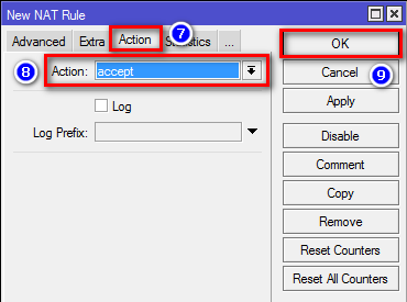
И с помощью захвата и перетаскивания мышью перетянем правило так, что бы оно находилось выше правила «masquerade«.

Через консоль
/ip ipsec peer
add address=10.1.200.1/32 hash-algorithm=sha1 enc-algorithm=aes-128 secret=ipsec-password send-initial-contact=no nat-traversal=no comment=filial1
/ip ipsec policy
add action=encrypt src-address=192.168.15.0/24 dst-address=192.168.25.0/24 sa-src-address=10.1.100.1 sa-dst-address=10.1.200.1 ipsec-protocols=esp tunnel=yes comment=filial1
/ip firewall nat
add chain=srcnat action=accept place-before=0 src-address=192.168.15.0/24 dst-address=192.168.25.0/24
Настройка второго маршрутизатора
Через графический интерфейс
Расписывать заново каждое действие мы не будем, т. к. они полностью аналогичны настройкам на первом маршрутизаторе.
Настройка IPsec-пира.

Настройка политики IPsec.


Правило обхода NAT.


Через консоль
/ip ipsec peer
add address=10.1.100.1/32 hash-algorithm=sha1 enc-algorithm=aes-128 secret=ipsec-password send-initial-contact=yes nat-traversal=no comment=HQ
/ip ipsec policy
add action=encrypt src-address=192.168.25.0/24 dst-address=192.168.15.0/24 sa-src-address=10.1.200.1 sa-dst-address=10.1.100.1 ipsec-protocols=esp protocol=all tunnel=yes comment=HQ
/ip firewall nat
add chain=srcnat action=accept place-before=0 src-address=192.168.25.0/24 dst-address=192.168.15.0/24
Настройка маршрутизации
Маршрутизация при использовании IPsec «в чистом виде» не может быть использована, т. к. IPsec не создает виртуальный интерфейс, которому может быть назначен IP-адрес и добавлена запись в таблицу маршрутизации.
Следует учесть
- AES является единственным алгоритмом, который поддерживается модулем аппаратного шифрования, если такой установлен на маршрутизатор.
- Максимальное значение MTU при котором не будет фрагментации с использованием IPsec с алгоритмами SHA1 для подписи и AES-128 для шифрования = 1418. При использовании других алгоритмов значение MTU будет другим. Если используется механизм обхода NAT IPsec, следует понизить MTU на 28.
- AES является единственным алгоритмом, который поддерживается модулем аппаратного шифрования, если такой установлен на маршрутизатор.
- IPSec очень не стабильно работает за NAT’ом. Поэтому желательно, что бы внешние интерфейсы маршрутизаторов имели «белые» IP-адреса.
Проверка
Через графический интерфейс
Если IPSec-соединение установлено успешно, то в графе Established должен появиться таймер времени (5), который показывает, как давно установлено соединение. Индикатором является именно наличие таймера, а не факт наличия соединения (4), которое в случае проблем будет отображаться, но таймер будет отсутствовать.

Через консоль
Выполнить команду /ip ipsec policy print stats, которая покажет актуальное состояние соединения IPSec. В случае удачи мы должны получить: ph2-state=established.
GW1:

GW2:

Состояние established через консоль будет отображаться только после того, как между двумя сетями произойдет попытка соединения. Например будет запущен ping. До тех пор пока соединение не будет установлено будет отображаться статус no-phase2. При этом через графический интерфейс всегда будет отображаться актуальная информация.
Типичные проблемы
- Если VPN-соединение между двумя маршрутизаторами MikroTik не устанавливается, то надо проверить:
- Не мешает ли файервол. Для уверенности лучше временно отключить все правила файерволов на обоих маршрутизаторах.
- Совпадают ли пароли (Secret) на обоих маршрутизаторах.
- Указан правильный адрес узла (peer) к которому должно происходить подключение.
- Совпадают ли способ аутентификации и алгоритм шифрования на обоих маршрутизаторах МикроТик. В приведенном примере использовался предопределенный proposal с настройками по умолчанию.