Introduction
This document describes how to configure the Network Address Translation (NAT) on a Cisco router.
Prerequisites
Requirements
This document requires a basic knowledge of the terms used in connection with NAT.
Components Used
The information in this document is based on these software and hardware versions:
-
Cisco 2500 Series Routers
-
Cisco IOS®Software Release 12.2 (10b)
The information in this document was created from the devices in a specific lab environment. All of the devices used in this document started with a cleared (default) configuration. If your network is live, ensure that you understand the potential impact of any command.
Conventions
Refer to Cisco Technical Tips Conventions for more information on document conventions.
Quick Start Steps to Configure and Deploy NAT
Note: In this document, when the internet, or an internet device is referred to, it means a device on any external network.
When you configure NAT, it is sometimes difficult to know where to begin, especially if you are new to NAT. These steps guide you to define what you want NAT to do and how to configure it:
-
Define NAT inside and outside interfaces .
-
Do users exist off multiple interfaces?
-
Are there multiple interfaces available to the internet?
-
-
Define what you want to accomplish with NAT.
-
Do you want to allow internal users to access the internet ?
-
Do you want to allow the internet to access internal devices (such as a mail server or web server)?
-
Do you want to redirect TCP traffic to another TCP port or address ?
-
Do you want to use NAT during a network transition (for example, you changed a server IP address and until you can update all the clients you want the non-updated clients to be able to access the server with the original IP address as well as allow the updated clients to access the server with the new address)?
-
Do you want to use to allow networks that overlap to communicate ?
-
-
Configure NAT in order to accomplish what you defined previously. Based on what you defined in step 2, you need determine which of the next features to use:
-
Static NAT
-
Dynamic NAT
-
Overloading -
Any combination of these features.
-
-
Verify the NAT operation.
Each of these NAT examples guides you through steps 1 through 3 of the Quick Start Steps in the previous image. These examples describe some common scenarios in which Cisco recommends you deploy NAT.
Define NAT Inside and Outside Interfaces
The first step to deploy NAT is to define NAT inside and outside interfaces. You can find it easiest to define your internal network as inside, and the external network as outside. However, the terms internal and external are subject to arbitration as well. This figure shows an example of this.
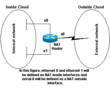 NAT Topology
Examples
1. Allow Internal Users to Access the Internet
Is possible that you want to allow internal users to access the internet, but you do not have enough valid addresses to accommodate everyone. If all communication with devices in the internet originate from the internal devices, you need a single valid address or a pool of valid addresses.
This figure shows a simple network diagram with the router interfaces defined as inside and outside.
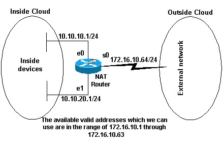 Available Valid Addresses
In this example, you want NAT to allow certain devices (the first 31 from each subnet) on the inside to originate communication with devices on the outside and translates their invalid address to a valid address or pool of addresses. The pool has been defined as the range of addresses 172.16.10.1 through 172.16.10.63.
You can now configure NAT. In order to accomplish what is defined in the previous image, use dynamic NAT. With dynamic NAT, the translation table in the router is initially empty and gets populated once traffic that needs to be translated passes through the router. As opposed to static NAT, where a translation is statically configured and is placed in the translation table without the need for any traffic.
In this example, you can configure NAT to translate each of the inside devices to a unique valid address, or to translate each of the inside devices to the same valid address. This second method is known as overloading . An example of how to configure each method is given here.
Configure NAT to Allow Internal Users to Access the Internet
| NAT Router |
|---|
interface ethernet 0 ip address 10.10.10.1 255.255.255.0 ip nat inside !--- Defines Ethernet 0 with an IP address and as a NAT inside interface. interface ethernet 1 ip address 10.10.20.1 255.255.255.0 ip nat inside !--- Defines Ethernet 1 with an IP address and as a NAT inside interface. interface serial 0 ip address 172.16.10.64 255.255.255.0 ip nat outside !--- Defines serial 0 with an IP address and as a NAT outside interface. ip nat pool no-overload 172.16.10.1 172.16.10.63 prefix 24 !--- Defines a NAT pool named no-overload with a range of addresses |
Note: Cisco highly recommends that you do not configure access lists referenced by NAT commands with permit any. If you use permit any in NAT, it consumes too many router resources which can cause network problems.
Notice in the previous configuration that only the first 32 addresses from subnet 10.10.10.0 and the first 32 addresses from subnet 10.10.20.0 are permitted by access-list 7 . Therefore, only these source addresses are translated. There can be other devices with other addresses on the inside network, but these are not translated.
The final step is to verify that NAT is operates as intended .
Configure NAT to Allow Internal Users to Access the Internet with Overload
| NAT Router |
|---|
interface ethernet 0 ip address 10.10.10.1 255.255.255.0 ip nat inside !--- Defines Ethernet 0 with an IP address and as a NAT inside interface. interface ethernet 1 ip address 10.10.20.1 255.255.255.0 ip nat inside !--- Defines Ethernet 1 with an IP address and as a NAT inside interface. interface serial 0 ip address 172.16.10.64 255.255.255.0 ip nat outside !--- Defines serial 0 with an IP address and as a NAT outside interface. ip nat pool ovrld 172.16.10.1 172.16.10.1 prefix 24 |
Notice in the previous second configuration, the NAT pool ovrld only has a range of one address. The keyword overload used in the ip nat inside source list 7 pool ovrld overload command allows NAT to translate multiple inside devices to the single address in the pool.
Another variation of this command is ip nat inside source list 7 interface serial 0 overload , which configures NAT to overload on the address that is assigned to the serial 0 interface.
When overloading is configured, the router maintains enough information from higher-level protocols (for example, TCP or UDP port numbers) to translate the global address back to the correct local address. For definitions of global and local address, refer to NAT: Global and Local Definitions .
The final step is to verify that NAT is operates as intended .
2. Allow the Internet to Access Internal Devices
You can need internal devices to exchange information with devices on the internet, where the communication is initiated from the internet devices, for example, email. It is typical for devices on the internet to send email to a mail server that resides on the internal network.
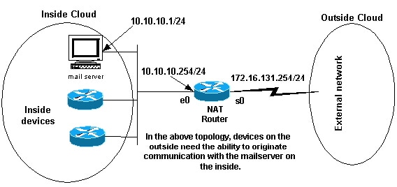 Originate Communications
Configure NAT to Allow the Internet to Access Internal Devices
In this example, you first define the NAT inside and outside interfaces, as shown in the previous network diagram.
Second, you define that you want users on the inside to be able to originate communication with the outside. Devices on the outside must be able to originate communication with only the mail server on the inside.
The third step is to configure NAT. To accomplish what you have defined, you can configure static and dynamic NAT together. For more information on how to configure this example, refer to Configure Static and Dynamic NAT Simultaneously . The final step is to verify that NAT operates as intended .
3. Redirect TCP Traffic to Another TCP Port or Address
A web server on the internal network is another example of when it can be necessary for devices on the internet to initiate communication with internal devices. In some cases, the internal web server can be configured to listen for web traffic on a TCP port other than port 80. For example, the internal web server can be configured to listen to TCP port 8080. In this case, you can use NAT to redirect traffic destined to TCP port 80 to TCP port 8080.
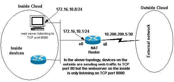 Web Traffic TCP Port
After you define the interfaces as shown in the previous network diagram, you can decide that you want NAT to redirect packets from the outside destined for 172.16.10.8:80 to 172.16.10.8:8080. You can use a static nat command in order to translate the TCP port number to achieve this. A sample configuration is shown here.
Configure NAT to Redirect TCP Traffic to Another TCP Port or Address
| NAT Router |
|---|
interface ethernet 0 ip address 172.16.10.1 255.255.255.0 ip nat inside !--- Defines Ethernet 0 with an IP address and as a NAT inside interface. interface serial 0 ip address 10.200.200.5 255.255.255.252 ip nat outside !--- Defines serial 0 with an IP address and as a NAT outside interface. ip nat inside source static tcp 172.16.10.8 8080 172.16.10.8 80 !--- Static NAT command that states any packet received in the inside |
Note: The configuration description for the static NAT command indicates any packet received in the inside interface with a source address of 172.16.10.8:8080 is translated to 172.16.10.8:80. This also implies that any packet received on the outside interface with a destination address of 172.16.10.8:80 has the destination translated to 172.16.10.8:8080.
The final step is to verify that NAT operates as intended .
show ip nat translations
Pro Inside global      Inside local       Outside local      Outside global
tcp 172.16.10.8:80     172.16.10.8:8080   ---                ---
4. Use NAT For a Network Transition
NAT is useful when you need to readdress devices on the network or when you replace one device with another. For instance, if all devices in the network use a particular server and this server needs to be replaced with a new one that has a new IP address, the reconfiguration of all the network devices to use the new server address takes some time. In the meantime, you can use NAT in order to configure the devices with the old address to translate their packets to communicate with the new server.
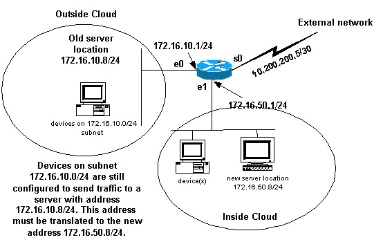 NAT Network Transition
Once you have defined the NAT interfaces as the previous image illustrates, you can decide that you want NAT to allow packets from the outside destined for the old server address (172.16.10.8) to be translated and sent to the new server address. Note that the new server is on another LAN, and devices on this LAN or any devices reachable through this LAN (devices on the inside part of the network), must be configured to use the new server IP address if possible.
You can use static NAT to accomplish what you need. This is a sample configuration.
Configure NAT for Use Through a Network Transition
| NAT Router |
|---|
interface ethernet 0 ip address 172.16.10.1 255.255.255.0 ip nat outside !--- Defines Ethernet 0 with an IP address and as a NAT outside interface. interface ethernet 1 ip address 172.16.50.1 255.255.255.0 ip nat inside !--- Defines Ethernet 1 with an IP address and as a NAT inside interface. interface serial 0 ip address 10.200.200.5 255.255.255.252 !--- Defines serial 0 with an IP address. This interface is not |
Note: The inside source NAT command in this example also implies that packets received on the outside interface with a destination address of 172.16.10.8 has the destination address translated to 172.16.50.8.
The final step is to verify that NAT operates as intended .
5. Use NAT for Networks that Overlap
Networks that overlap result when you assign IP addresses to internal devices that are already used by other devices within the internet. These networks also result when two companies, both of whom use RFC 1918 IP addresses in their networks, merge. These two networks need to communicate, preferably without all of their devices readdressed.
Difference between One-to-One and Many-to-Many Mapping
A static NAT configuration creates a one-to-one mapping and translates a specific address to another address. This type of configuration creates a permanent entry in the NAT table as long as the configuration is present and enables both inside and outside hosts to initiate a connection. This is mostly useful for hosts that provide application services like mail, web, FTP and so forth. For example:
Router(config)#ip nat inside source static 10.3.2.11 10.41.10.12
Router(config)#ip nat inside source static 10.3.2.12 10.41.10.13
Dynamic NAT is useful when fewer addresses are available than the actual number of hosts to be translated. It creates an entry in the NAT table when the host initiates a connection and establishes a one-to-one mapping between the addresses. But, the mapping can vary and it depends upon the registered address available in the pool at the time of the communication. Dynamic NAT allows sessions to be initiated only from inside or outside networks for which it is configured. Dynamic NAT entries are removed from the translation table if the host does not communicate for a specific period of time which is configurable. The address is then returned to the pool for use by another host.
For example, complete these steps of the detailed configuration:
-
Create a pool of addresses
Router(config)#ip nat pool MYPOOLEXAMPLE 10.41.10.1 10.41.10.41 netmask 255.255.255.0
-
Create an access-list for the inside networks that has to be mapped
Router(config)#access-list 100 permit ip 10.3.2.0 0.0.0.255 any
-
Associate the access-list 100 that select the internal network 10.3.2.0 0.0.0.255 to be natted to the pool MYPOOLEXAMPLE and then overload the addresses.
Router(config)#ip nat inside source list 100 pool MYPOOLEXAMPLE overload
Verify the NAT Operation
Once you have configured NAT, verify that it operates as expected. You can do this in a number of ways: with a network analyzer, show commands, or debug commands. For a detailed example of NAT verification, refer to Verify NAT Operation and Basic NAT .
Conclusion
The examples in this document demonstrate quick start steps can help you configure and deploy NAT.
These quick start steps include:
-
Define NAT inside and outside interfaces.
-
What do you want to accomplish with NAT.
-
Configure NAT in order to accomplish what you defined in Step 2.
-
Verify the NAT operation.
In each of the previous examples, various forms of the ip nat inside command were used. You can also use the ip nat outside command in order to accomplish the same objectives, but keep in mind the NAT order of operations. For configuration examples that use the ip nat outside commands, refer to Sample Configuration that Uses the IP NAT Outside Source List Command .
The previous examples also demonstrated these actions:
| Command | Action |
|---|---|
| ip nat inside source |
|
| ip nat outside source |
|
Related Information
- NAT: Local and Global Definitions.
- NAT Support Page
- IP Routed Protocols Support Page
- IP Routing Support Page
- IP Addressing Services
- NAT Order of Operation
- Frequently Asked Questions about Cisco IOS NAT
- Technical Support & Documentation — Cisco Systems
Время на прочтение
8 мин
Количество просмотров 281K
Добрый день, коллеги!
судя по многочисленным вопросам на форуме (ссылка в конце поста), от слушателей и коллег, работа NAT на маршрутизаторах Cisco (firewall’ы я опущу, Fedia достаточно подробно его работу расписал в своей серии статей про Cisco ASA) плохо описана, поэтому я попробую описать свой опыт и свое понимание данной технологии в большинстве ее ипостасей. Не претендую на всеобъемлющее описание и 100% точность, но кому интересно — велкам под кат.
Итак, для структурности описания разберемся с определением, что такое NAT.
Определение
. NAT (Network Address Translation) — технология трансляции сетевых адресов, т.е. подмены адресов в заголовке IP-пакета (иногда может еще и порт менять в заголовках TCP/UDP, но об этом позже).
Другими словами, пакет, проходя через маршрутизатор, может поменять свой адрес источника и/или назначения.
Зачем это нужно
?
1. Для обеспечения доступа из LAN, где чаще всего используются частные IP-адреса, в Internet, где маршрутизируются только глобальные IP-адреса.
2. (в меньшей степени) для сокрытия топологии сети и создания некоторого защитного барьера для проникновения внутрь сети (обсудим это позже на примере).
NAT бывает разным  И хотя много по этому поводу уже написано, есть желание отправлять новичков с вопросами о NAT по конкретному адресу, поэтому я все же приведу некоторую
классификацию
.
1. Static NAT — статический NAT задает однозначное соответствие одного адреса другому. Иными словами, при прохождении через маршрутизатор, адрес(а) меняются на строго заданный адрес, один-к-одному. (к примеру 10.1.1.1 всегда заменяется на 11.1.1.1 и обратно, но никогда на 12.1.1.1). Запись о такой трансляции хранится неограниченно долго, пока есть строчка в конфиге.
2. Dynamic NAT — при прохождении через маршрутизатор, новый адрес выбирается динамически из некоторого куска адресов, называемого пулом (англ. pool). Запись о трансляции хранится некоторое время, чтобы ответные пакеты могли быть доставлены адресату. Если в течение некоторого времени трафик по этой трансляции отсутствует, трансляция удаляется и адрес возвращается в пул. Если требуется создать трансляцию, а свободных адресов в пуле нет, то пакет отбрасывается. Иными словами, хорошо бы, чтобы число внутренних адресов было ненамного больше числа адресов в пуле, иначе высока вероятность проблем с доступом наружу.
3. Dynamic NAT with overload или PAT. Работает почти также, как dynamic NAT, но при этом происходит трансляция много-в-один, задействуя при этом возможности транспортного уровня. Об этом подробнее на примере дальше.
Поскольку я чаще всего работаю именно с железом Cisco, я опишу в статье именно особенности работы и возможные варианты NAT именно на этих железках.
Давайте посмотрим, что у нас есть в этом случае.
1. inside source NAT
Самый распространенный и достаточно простой вариант. Допустим у нас есть такая топология:

Другими словами,
а) подсеть внутренних адресов — 10.0.0.0/8
б) подсеть внешних адресов — 11.0.0.0/8
и мы хотим транслировать каким-то образом внутренние адреса во внешние при прохождении трафика через маршрутизатор.
Что для этого нужно?
1. Мы явно указываем, что мы хотим транслировать. Т.е. какой трафик и от каких хостов.
2. Мы явно указываем, во что мы хотим траслировать, т.е. пул внешних адресов (или единственный адрес для статической трансляции).
3. Помечаем внутренний и внешний интерфейс.
4. Включаем трансляцию.
На п.3 я себе позволю остановиться подробнее, потому что именно здесь часто происходит непонимание.
Как это работает?
Итак, допустим мы решили, что будем транслировать всю 10ю сеть целиком в 11ю. Задали их соответствующим образом (настройки потом, сначала теория). И пометили наши интерфейсы как внутренний (inside) и внешний (outside).
Теперь, давайте разберемся, что делает именно inside source NAT. На самом деле, в названии зашита половина действия а именно: у пакета, пришедшего на
inside
интерфейс меняется
source
:). Но помните, мы говорили о том, что ответные пакеты должны доходить до нашего внутреннего хоста? Отсюда вторая половина действия: у пакета, пришедшего на
outside
интерфейс меняется
destination
.
Рассмотрим
прямую трансляцию
.
1. Трафик, приходя на интерфейс, помеченный как inside, если он соответствует тому, что мы хотим транслировать, маркируется как возможно_транслируемый. Часто полагают, что в этот момент происходит трансляция, но это не так.
2. Следующим этапом, трафик подвеграется маршрутизации (PBR и обычной). И если при этом трафик направляется на интерфейс, помеченный как outside — только тогда происходит трансляция. Если трансляция динамическая, маршрутизатор проверяет ее наличие в таблице трансляций. Если ее там нет — создает, если уже есть — обнуляет счетчик неактивности. Если же пакет попадает на выход на интерфейс, не помеченный как outside — трансляция НЕ происходит.
Теперь
обратная трансляция
.
1. Трафик, попадая на outside интерфейс, в противовес прямой трансляции, сначала подвергается NAT. Если трансляция существует (неважно, динамическая или статическая), в случае с inside source NAT, у него меняется destination. И только после этого трафик подвергается маршрутизации и перенаправляется по назначению.
Поэтому маркировать интерфейсы как inside или outside нужно именно принимая во внимание механизм работы.
Замечания и следствия
.
1. Для обратной трансляции не обязательно наличие метки inside на каком-либо интерфейсе. Все равно, если прямая трансляция существует, обратная трансляция сработает до маршрутизации. Но когда будет существовать такая трансляция, ведь мы обсуждали, что трафик должен пройти через inside интерфейс для создания прямой трансляции? Отсюда
2. Трафик самого роутера подвергается трансляции, если он попадает на интерфейс, помеченный как outside и удовлетворяет правилу NAT. И это сколь полезно, столь и опасно. С одной стороны, мы можем транслировать трафик роутера как и любой другой. С другой стороны, многие хотят описать трафик, подлежащий трансляции как permit any, но тогда и, например, пакеты протоколов маршрутизации будут транслироваться, что приведет к сбою.
3. Интерфейсы типа loopback маршрутизатора трактуются как и любые другие, мы можем метить их как inside или outside, заворачивать на них трафик и получать от этого профит
Теперь посмотрим общую конфигурацию, а потом еще несколько частных случаев.
Конфигурация inside source NAT
inside source dynamic NAT
1. Указываем, что транслировать. Для этого создаем access-list, перечисляющий трафик. Например, в нашем случае достаточно одной строчки:
(config)# access-list 100 permit ip 10.0.0.0 0.255.255.255 any
Замечание
. В ACL могут встречаться строчки deny. Вопреки распространенному заблуждению, трафик удовлетворяющей данной строчке не дропается, а просто не подвеграется трансляции. Так же, ACL может быть стандартным и расширенным, нумерованным и именованным.
2. Создаем пул из адресов, указывая стартовый и конечный адрес. Например так:
(config)# ip nat pool NAME_OF_POOL 11.1.1.10 11.1.1.20 netmask 255.255.255.0
Замечания
.
1. Стартовый и конечный адрес в пуле могут совпадать, тогда трансляция будет в 1 адрес.
2. Опция netmask, хотя и является обязательной, по моему мнению — рудимент. Она позволяет вырезать из диапазона адресов в пуле те адреса, которые являются адресами подсети или бродкастными при данной маске.
3. Маркируем интерфейсы. В нашем случае достаточно
(config)# interface fa 0/0

 (config-if)# ip nat inside
и
(config)# interface fa 0/1

 (config-if)# ip nat outside
4. создаем собственно трансляцию:
ip nat inside source list 100 pool NAME_OF_POOL
вуаля Если мы теперь обратимся например с хоста 10.1.1.1 к хосту 11.1.1.2, то получим такую трансляцию:
Router#sh ip nat translations

 Pro Inside global Inside local Outside local Outside global

 tcp 11.1.1.10:55209 10.0.1.1:55209 11.1.1.2:23 11.1.1.2:23
Интересно, что хотя в таблице явно записаны source port и destination port, трансляция создается целиком для адреса. И на время ее жизни в таблице трансляция, пакеты снаружи могут проходить на внешний адрес (inside global)
Например, пинг с некоторого адреса во внешней сети на наш inside global будет успешным (на время жизни трансляции):
R4#ping 11.1.1.10

 Type escape sequence to abort.

 Sending 5, 100-byte ICMP Echos to 11.1.1.10, timeout is 2 seconds:

 !!!!!
Иными словами, открывается трансляция единожды и к некоторому хосту, после этого некоторое время действует для любого адреса извне.
inside source dynamic NAT with overload
П. 1,2 и 3 — как в предыдущем разделе.
4. Создаем собственно трансляцию:
ip nat inside source list 100 pool NAME_OF_POOL overload
Видим, что добавилось всего одно слово: overload. Но оно существенно изменило схему работы трансляции.
Как было сказано, PAT — это трансляция много-в-мало или даже много-в-один. Но чтобы можно было отличить трафик одного соединения от другого, маршрутизатор будет менять не только IP-адреса, но еще и TCP/UDP порты.
Замечание
. Схема работы с портами (когда меняется source, когда destination) — такая же, как и схема работы с IP-адресами.
Другими словами, при обращении изнутри наружу меняется source IP и source port, запись об этом вносится в таблицу трансляций. При обратной трансляции — все меняется наоборот.
Посмотрим, что изменилось:
R3#sh ip nat translations

 Pro Inside global Inside local Outside local Outside global

 tcp 11.1.1.11:21545 10.0.1.1:21545 11.1.1.2:23 11.1.1.2:23

 tcp 11.1.1.11:49000 10.0.2.1:49000 11.1.1.2:23 11.1.1.2:23
Видим, что разные внутренние адреса (10.0.1.1 и 10.0.2.1) странслировались в один внешний (11.1.1.11).
Замечания
.
1. Кажется, что source-port не был изменен, как обещали, непорядок :). На деле, маршрутизатор пытается сохранить source port всеми доступными средствами. В частности, если порт inside global адреса уже был занят, он возьмет следующий адрес в пуле и проверит его порт на занятость. И только не найдя адреса со свободным портом возьмет следующий свободный.
2. Поведение такой трансляции отличается от поведения обычного dynamic NAT еще и тем, что доступ снаружи на inside global адрес невозможен. Именно это я имел ввиду, когда говорил о некоторой повышенной безопасности при использовании PAT, т.к. фактически все соединения инициируются изнутри нашей сети, а снаружи нам могут приходить только ответы на них.
3. Если мы получили у провайдера не целый блок адресов, а один несчастный адрес, который тут же и назначили внешнему интерфейсу маршрутизатора, можно не городить огород с пулом в один адрес, а сразу писать например так:
(config)# ip nat inside source list 100 interface fa0/1 overload
inside source static NAT and PAT
Много упоминалось о статических трансляциях, давайте наконец их обсудим.
Зачем это нужно?
Мы обсудили, что если в случае dynamic NAT трансляция не создана и в случае PAT, доступ извне невозможен. Если даже в случае dynamic NAT трансляция создана, то inside global адрес может меняться. И обращаться к нашему внутреннему хосту по какому-то внешнему адресу невозможно.
Тем не менее, нередки ситуации, когда внутри корпоративной сети есть сервер, доступ которому извне по статическому внешнему адресу жизненно необходим. В таком случае, можно выставить его прямиком в Интернет, назначив глобальный адрес. Но часто это не очень удобно, например по соображениям безопасности. И в таких случаях нам на помощь приходит static NAT.
Он создает двустороннюю и постоянную трансляцию. Так что наш хост всегда будет доступен по одному внешнему адресу и эта трансляция никогда не вылетит из таблицы трансляций по таймауту.
собственно настройка.
Сразу создаем трансляцию:
(config)# ip nat inside source static 10.0.1.1 11.1.1.21
Маркируем интерфейсы и вуаля!
R3#sh ip nat translations

Pro Inside global Inside local Outside local Outside global

icmp 11.1.1.21:14 10.0.1.1:14 11.1.1.2:14 11.1.1.2:14

--- 11.1.1.21 10.0.1.1 --- ---
Как видим, появилось две записи — одна постоянная, другая (чисто информативная) — временная, вызванная трафиком изнутри наружу.
Замечание
. Появление таких информативных записей можно отключить командой
(config)# no ip nat create flow-entries
Идем дальше. Часто бывает, что нужно выставить наружу не целый адрес, а только один порт (например 80й для www-сервера). Никаких проблем, можно создать и статическую PAT-трансляцию для некоторых портов:
(config)# ip nat inside source static tcp 10.0.1.1 80 11.1.1.21 80

(config)# ip nat inside source static udp 10.0.1.1 5060 11.1.1.21 7877
Видим, что порты одного и того же внешнего адреса можно пробрасывать на разные порты внутренних, и управлять трансляцией портов при этом тоже возможен.
В заключение добавлю, что изменять различные таймауты для NAT можно командой
Router(config)#ip nat translation ?

 arp-ping-timeout Specify timeout for WLAN-NAT ARP-Ping

 dns-timeout Specify timeout for NAT DNS flows

 finrst-timeout Specify timeout for NAT TCP flows after a FIN or RST

 icmp-timeout Specify timeout for NAT ICMP flows

 max-entries Specify maximum number of NAT entries

 port-timeout Specify timeout for NAT TCP/UDP port specific flows

 pptp-timeout Specify timeout for NAT PPTP flows

 routemap-entry-timeout Specify timeout for routemap created half entry

 syn-timeout Specify timeout for NAT TCP flows after a SYN and no

 further data

 tcp-timeout Specify timeout for NAT TCP flows

 timeout Specify timeout for dynamic NAT translations

 udp-timeout Specify timeout for NAT UDP flows
Объемистая статейка получилась, придется разбить на несколько частей. Конечно inside source NAT многократно обсужден и расписан, но надеюсь, что даже не совсем новичкам удастся найти в статье что-то полезное. Надо было начать с некоторой базы, пусть и общеизвестной.
В следующей статье мы обсудим inside destination NAT, если конечно статья найдет отклик и поддержку.
С уважением,
Подкопаев Илья
P.S. Я открыт для пожеланий по улучшению статьи и исправлению неточностей/ошибок.
P.P.S. Ссылки:
1. форум сайта anticisco.ru
2. Cisco NAT order of operations
Cisco как настроить NAT
Сегодня мы рассмотрим как быстро настроить NAT на роутере Cisco без лишних настроек и прочего, просто NAT.
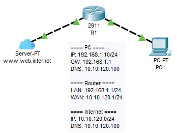
Эмуляция задания будет в ПО Cisco Packet Tracer. Итак приступим.
Разместим в рабочую область 3 устройства.
- Роутер Cisco
- Компьютер
- Сервер (будет выполнять роль эмуляции интернет сервисов)

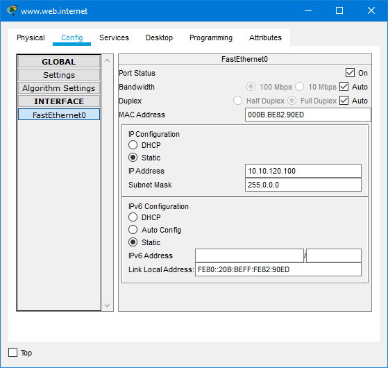
Конфигурация сети у нас следующая:
- ПК
- IP: 192.168.1.10/24
- GW: 192.168.1.1
- DNS: 10.10.120.100
- Router
- LAN: 192.168.1.1/24
- WAN: 10.10.120.1/24
- Internet
- IP: 10.10.120.0/24
- DNS: 10.10.120.100
Настраиваем ПК по таблице
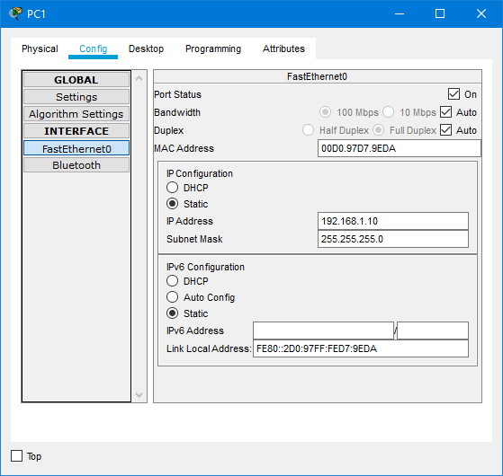
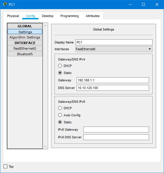
Ок. Готово
Теперь приступим к настройке нашего роутера
Открываем консоль и пишем следующее
Router>en
Router#conf t
Router(config)#hostname R1
R1#
Это мы сейчас назвали роутер «R1». Теперь настроим интерфейсы
R1(config)#interface gigabitEthernet0/0
R1(config-if)#ip address 192.168.1.1 255.255.255.0
R1(config-if)#description LAN
R1(config-if)#no shutdown
R1(config-if)#ex

R1(config)#int gig0/1
R1(config-if)#ip add 10.10.120.1 255.255.255.0
R1(config-if)#description WAN
R1(config-if)#no shutdown
R1(config-if)#ex
В итоге мы имеем два интерфейса
- gigabitEthernet0/0 — для локальной сети, для ПК
- gigabitEthernet0/1 — для интернет
Теперь настраиваем на роутере Cisco NAT
R1(config)#access-list 1 permit 192.168.1.0 0.0.1.255
R1(config)#ip nat inside source list 1 interface GigabitEthernet0/1 overload

R1(config)#interface GigabitEthernet0/0
R1(config-if)#ip nat inside
R1(config-if)#exit

R1(config)#interface GigabitEthernet0/1
R1(config-if)#ip nat outside
R1(config-if)#exit
Всё. С настройкой NAT и роутера закончили. (Сохраняем конфиг)
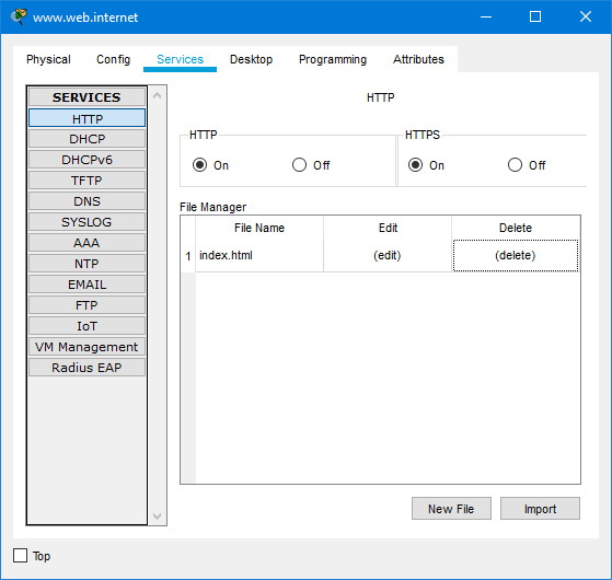
Теперь раз уж мы эмулируем работу сервисов интернет настроим сервер

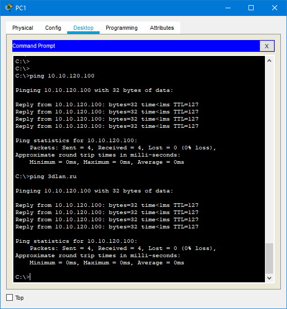
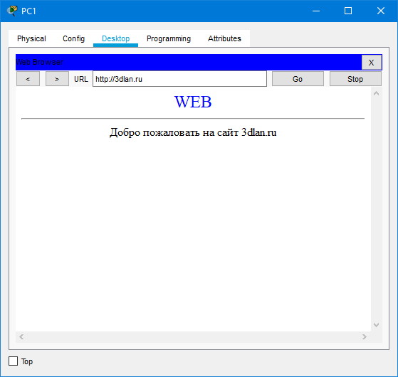
Проверяем с ПК
Проверяем на роутере
R1#show ip nat translations
Pro  Inside global     Inside local       Outside local      Outside global
udp 10.10.120.1:1025   192.168.1.10:1025  10.10.120.100:53   10.10.120.100:53
udp 10.10.120.1:1026   192.168.1.10:1026  10.10.120.100:53   10.10.120.100:53
tcp 10.10.120.1:1025   192.168.1.10:1025  10.10.120.100:80   10.10.120.100:80
tcp 10.10.120.1:1026   192.168.1.10:1026  10.10.120.100:80   10.10.120.100:80
tcp 10.10.120.1:1027   192.168.1.10:1027  10.10.120.100:80   10.10.120.100:80
tcp 10.10.120.1:1028   192.168.1.10:1028  10.10.120.100:80   10.10.120.100:80
tcp 10.10.120.1:1029   192.168.1.10:1029  10.10.120.100:80   10.10.120.100:80

R1#show ip nat statistics
Total translations: 7 (0 static, 7 dynamic, 7 extended)
Outside Interfaces: GigabitEthernet0/1
Inside Interfaces: GigabitEthernet0/0
Hits: 69  Misses: 49
Expired translations: 38
Dynamic mappings:
R1#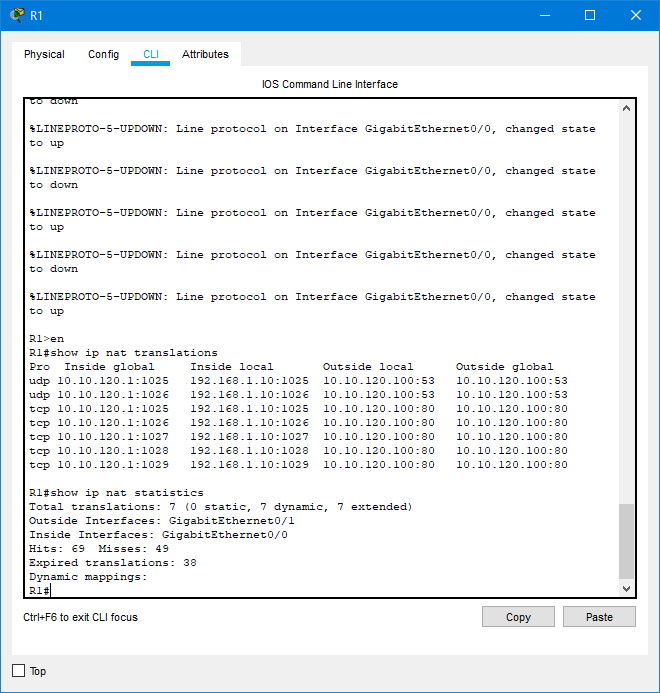
Готово.
NAT (Network Address Translation) — это процесс трансляции локальных (частных) ip-адресов во внешние (глобальные), позволяет узлам, имеющим частные адреса, обмениваться данными в сети Интернет.
При настройке NAT, один интерфейс должен быть определен как внутренний (соединяется с внутренней частной сетью), а другой как внешний (используется для выхода в Интернет).
Используется 3 вида трансляции адресов
1. Статический (Static Network Address Translation)
2. Динамический (Dynamic Address Translation)
3. Маскарадный (NAPT, NAT Overload, PAT)
Настройка статического NAT (Static Network Address Translation)
Статический NAT — сопоставляет единый внутренний локальный (частный) ip-адрес с единым глобальным (публичным) ip-адресом.

1.Создание статического маршрута на стороне ISP.
R2(config)# ip route 200.20.21.1 255.255.255.224 200.20.20.1
2.Настройка дефолта на R1.
R1(config)# ip route 0.0.0.0 0.0.0.0 200.20.20.2
3.Настройка внутреннего интерфейса в отношение NAT.
R1(config)# interface fastethernet 0/0
R1(config-if)# ip nat inside
4.Настройка внешнего интерфейса в отношение NAT.
R1(config)# interface fastethernet 0/1
R1(config-if)# ip nat outside
5.Настройка сопоставления ip-адресов.
R1(config)# ip nat inside source static 10.10.10.2 200.10.21.5
В результате ip-адресу 200.10.21.5 всегда будет соответствовать внутренний ip-адрес 10.10.10.2, т.е. если мы будем обращаться к адресу 200.10.21.5 то отвечать будет computer 1
<р2>Настройка динамического NAT (Dynamic Address Translation)
Динамический NAT — использует пул доступных глобальных (публичных) ip-адресов и назначает их внутренним локальным (частным) адресам.
1.Настройка списка доступа соответствующего внутренним частным адресам, обратите внимание что используется обратная маска.
R1(config)# access-list 1 permit 10.10.10.0 0.0.0.255
2.Настройка пула адресов.
R1(config)# ip nat pool white-address 200.20.21.1 200.20.21.30 netmask 255.255.255.0
3.Настройка трансляции.
R1(config)# ip nat inside source list 1 pool white-address
4.Настройка внутреннего интерфейса в отношение NAT.
R1(config)# interface fastethernet 0/0
R1(config-if)# ip nat inside
5.Настройка внешнего интерфейса в отношение NAT.
R1(config)# interface fastethernet 0/1
R1(config-if)# ip nat outside
Настройка PAT (NAPT, NAT Overload, маскарадинг)
PAT (Port Address Translation) — отображает несколько локальных (частных) ip-адресов в глобальный ip-адрес, используя различные порты.
1. Настройка списка доступа соответствующего внутренним частным адресам, обратите внимание что используется обратная маска.
R1(config)# access-list 1 permit 10.10.10.0 0.0.0.255
2. Настройка трансляции.
R1(config)# ip nat inside source list 1 interface fastethernet 0/1 overload
3.Настройка внутреннего интерфейса в отношение NAT.
R1(config)# interface fastethernet 0/0
R1(config-if)# ip nat inside
4.Настройка внешнего интерфейса в отношение NAT.
R1(config)# interface fastethernet 0/1
R1(config-if)# ip nat outside
Команды для проверки работы NAT
show ip nat translations - Выводит активные преобразования.
show ip nat statistics - выводит статистику по NAT преобразованиям.
На этом все. Всем пока.
Are you looking to configure a Cisco router for Internet access for the first time? Yes? Great! This post is for you then.
I am going to show you step-by-step a quick and easy way to configure a Cisco IOS router to provide Internet connectivity securely. After putting together a network design diagram, we’re going to execute the following tasks:
At the end of this post, your router should be ready to allow your users to access the Internet.
Are you ready? Let’s go.
Network Design Diagram
The first thing you need to do is to create a basic diagram to lay out all the IP addresses (private and public), physical interfaces (internal and external), and features you want to be turned on. Having a visual of your final network will make it easier for you to carry out the staging, testing, and implementation of your Internet router.

So we have the following information:
- ISP-facing interface: GigabitEthernet 0/0 (or Gi0/0)
- External/Public IP subnet: 165.13.70.64 255.255.255.252
- IP address assigned to the Internet Service Provider (ISP) end: 165.13.70.65
- IP address assigned to you (the customer): 165.13.70.66
- User-facing interface: GigabitEthernet 0/1 (or Gi0/1)
- Internal/Private IP subnet: 172.16.10.0 /24
- IP address assigned to the router: 172.16.10.1
Let’s now configure these IP addresses on the router’s interfaces.
Configure Router Interfaces
Your ISP should provide you with an Ethernet connection to their router. This line, however, could provide IP addresses dynamically via DHCP or statically (manually configured on the router).

In case the ISP’s line provides IP addresses dynamically, I’m going to give you the commands to allow your router to request and receive its public IP address from the ISP. Remember, the provider’s end has to be configured to provide an IP address with the DHCP protocol, which is the protocol used to assign IP addresses.
Router#config term
Enter configuration commands, one per line.  End with CNTL/Z.
Router(config)#interface gigabitEthernet 0/0
Router(config-if)#description INTERNET LINE
Router(config-if)#ip address dhcp
Router(config-if)#no ip proxy-arp
Router(config-if)#no ip unreachables
Router(config-if)#no ip redirects
Router(config-if)#no shutdown
Router(config-if)#exit
Router(config)#
In our case, the ISP gave you the IP address you need to assign to your router’s ISP-facing interface. I like to use Gi0/0 to connect the ISP’s Ethernet line. Here are the commands to configure an IP address on your Cisco router.
Router(config)#interface gigabitEthernet 0/0
Router(config-if)#description INTERNET LINE
Router(config-if)#ip address 165.13.70.66 255.255.255.252
Router(config-if)#no ip proxy-arp
Router(config-if)#no ip redirects
Router(config-if)#no ip unreachables
Router(config-if)#no shutdown
Router(config-if)#exit
Router(config)#
Now you need to tell your router that any IP packet it doesn’t have a route for, it needs to send it to the ISP. You need to configure a default route.
Router(config)#
Router(config)#ip route 0.0.0.0 0.0.0.0 165.13.70.65
Router(config)#end
Router#
Make sure that your Interface is up.
Router#show ip interface brief
Interface                  IP-Address      OK? Method Status                Protocol
GigabitEthernet0/0         165.13.70.66    YES manual up                    up
GigabitEthernet0/1         unassigned      YES unset  administratively down down
GigabitEthernet0/2         unassigned      YES unset  administratively down down
GigabitEthernet0/3         unassigned      YES unset  administratively down down
Router#
You can test connectivity to your ISP by pinging the ISP’s end of Internet line connected to Gi0/0.
Router#ping 165.13.70.65
Type escape sequence to abort.
Sending 5, 100-byte ICMP Echos to 165.13.70.65, timeout is 2 seconds:
!!!!!
Success rate is 100 percent (5/5), round-trip min/avg/max = 23/187/293 ms
Router#
You can test Internet connectivity by pinging a public IP device on the Internet. For instance, you can ping one of Google’s DNS servers 8.8.8.8.
Router#ping 8.8.8.8
Type escape sequence to abort.
Sending 5, 100-byte ICMP Echos to 8.8.8.8, timeout is 2 seconds:
!!!!!
Success rate is 100 percent (5/5), round-trip min/avg/max = 14/38/94 ms
Router#
Let’s configure now your internal IP address on interface Gi0/1.
Router#config term
Enter configuration commands, one per line.  End with CNTL/Z.
Router(config)#interface gigabitEthernet 0/1
Router(config-if)# description INTERNAL/PRIVATE SEGMENT
Router(config-if)# ip address 172.16.10.1 255.255.255.0
Router(config-if)# no ip proxy-arp
Router(config-if)# no ip redirects
Router(config-if)# no ip unreachables
Router(config-if)# no shutdown
Router(config-if)# exit
Router(config)#
Now that your router itself has Internet connectivity, let’s configure your router to provide IP addresses to your internal devices.
Configure DHCP Server
A Dynamic Host Configuration Protocol (DHCP) server is a service built into your router that allows your router to distribute IP addresses of a previously configured pool of addresses.
In our example, the network’s internal subnet is 172.16.10.0 /24 and the router has been assigned the 172.16.10.1 IP address to its Gi0/1 interface. You can tell the router to start assigning IP addresses starting from 172.16.10.11 through 172.16.10.254.

A /24 equals to 255.255.255.0. Decimal 255 is 11111111 (eight 1s) in binary. So, 255.255.255.0 equals to 11111111.11111111.11111111.0. And that is 24 bits. That’s why 255.255.255.0 is the same as a /24.
Router(config)#ip dhcp excluded-address 172.16.10.1 172.16.10.10
Router(config)#
Router(config)#ip dhcp pool INSIDE
Router(dhcp-config)# network 172.16.10.0 255.255.255.0
Router(dhcp-config)# dns-server 8.8.8.8 4.2.2.2
Router(dhcp-config)# default-router 172.16.10.1
Router(dhcp-config)#exit
Router(config)#exit
Router#
To check your DHCP Pool settings, use the show ip dhcp pool command:
Router#show ip dhcp pool

Pool INSIDE :
 Utilization mark (high/low)    : 100 / 0
 Subnet size (first/next)       : 0 / 0
 Total addresses                : 254
 Leased addresses               : 0
 Pending event                  : none
 1 subnet is currently in the pool :
 Current index        IP address range                    Leased addresses
 172.16.10.1          172.16.10.1      - 172.16.10.254     0
Router#
When a computer on the inside of the network comes up, that computer will request an IP address via a DHCP Request. When the router sees that request on its Gi0/1 interface, it’ll respond with an IP address from the pool of IPs you just configured. Since you excluded IPs from 172.16.10.1 through 172.16.10.10, the first available IP would be 172.16.10.11.

In addition to the IP address for the PC itself, the DHCP Reply message also contains the IP addresses of the DNS servers (8.8.8.8 and 4.2.2.2) and the default gateway (172.16.10.1) configured.
Notice that we’re using public DNS servers. Remember Internet communications happen in terms of IP addresses. When you type www.cisco.com on your browser, your computer sends a request to its DNS server assigned by DHCP, in our case is 8.8.8.8, and this server with an IP address related to www.cisco.com. Your browser then sends an HTTP request to that IP address to load the home page of www.cisco.com.
If 8.8.8.8 doesn’t respond, a request is sent to 4.2.2.2 as configured above.
A default gateway is used when your PC wants to talk to an IP address that belongs to anything outside its IP address group. For instance, your PC was assigned an IP address from a pool of IPs that starts with 172.16.10.1 through 172.16.10.254.
Your DHCP server, however, was also configured to exclude IPs from 172.16.10.1 through 172.16.10.10 for dynamic assigned. Nevertheless, all IPs from 172.16.10.1 through 172.16.10.254 belong to your group and therefore you can communicate with them directly. Anything outside of that group needs to be sent to the default gateway.
For that reason, when your computer needs to send a DNS request to 8.8.8.8, that request is sent to its default gateway, 172.16.10.1.
Use the show ip dhcp binding command to see what IP addresses have been assigned off the pool configured.
Router#show ip dhcp binding
Bindings from all pools not associated with VRF:
IP address          Client-ID/              Lease expiration        Type
                    Hardware address/
                    User name
172.16.10.11        0063.6973.636f.2d35.    Mar 07 2022 08:50 PM    Automatic
                    3235.342e.3030.3034.
                    2e30.3733.372d.4769.
                    302f.30
Router#
Notice that the first IP address assigned is the first IP available on the pool.
Configure NAT
The Internet doesn’t know how to talk to any of your PCs with an IP that starts with 172.16.10. That IP subnet is considered private, not routable on the Internet. The only public IP you have on your router is the IP address assigned to your Gi0/0 interface and that is 165.13.70.66.
Network Address Translation (NAT) is another service that can be activated on your router that allows your router to hide your private IP addresses behind your public IP. In other words, your router will convert any private IP range into a public IP or public range.
Simply put, anyone on the Internet won’t know that IP communications, such as browsing a web server, are coming from PCs with IPs within the 172.16.10.0 /24 private range. What the Internet will see is IP communications coming from 165.13.70.66 IP address. And this is thanks to NAT.

When you click on a link on a webpage, that click is a request to display the contents of the webpage the link is pointing to. That request leaves your PC as an IP packet sourced from the IP address of your PC and destined to the IP address of the web server that hosts that new webpage. Remember that the link is based on a name that is then resolved into an IP address by your DNS server.
To configure NAT on your router, enter the following commands:
Router(config)#interface gigabitEthernet 0/1
Router(config-if)#ip nat inside
Router(config-if)#exit
Router(config)#
Router(config)#interface gigabitEthernet 0/0
Router(config-if)#ip nat outside
Router(config-if)#exit
Router(config)#
Router(config)#ip access-list extended NAT-TRAFFIC
Router(config-ext-nacl)# permit ip 172.16.10.0 0.0.0.255 any
Router(config-ext-nacl)# exit
Router(config)#
Router(config)#ip nat inside source list NAT-TRAFFIC interface gigabitEthernet 0/0 overload
Router(config)#end
Router#
To look at the configuration, use the show ip nat statistics command:
Router#show ip nat statistics
Total active translations: 0 (0 static, 0 dynamic; 0 extended)
Peak translations: 1, occurred 00:03:59 ago
Outside interfaces:
  GigabitEthernet0/0
Inside interfaces:
  GigabitEthernet0/1
Hits: 200  Misses: 0
CEF Translated packets: 200, CEF Punted packets: 0
Expired translations: 1
Dynamic mappings:
-- Inside Source
[Id: 1] access-list NAT-TRAFFIC interface GigabitEthernet0/0 refcount 0

Total doors: 0
Appl doors: 0
Normal doors: 0
Queued Packets: 0
Router#
What we’re saying here is that all traffic sourced from any of the IP addresses that belong to the 172.16.10.0 /24 subnet that comes in Gi0/1, goes out Gi0/0, and is directed to ANY IP, replace that source IP of 172.16.10.X with the IP address configured on Gi0/0 interface.
So, for the Internet, traffic is coming from 165.13.70.66 and not from 172.16.10.X. In other words, 172.16.10.X is being replaced/impersonated by 165.13.70.66.
Router#show ip nat translations
Pro Inside global      Inside local       Outside local      Outside global
icmp 165.13.70.66:0    172.16.10.11:0     8.8.8.8:0          8.8.8.8:0
Router#
The Inside Local IP is the original IP. The Inside Global is the NAT IP that’s impersonating the original IP. The Outside Local and Global are the destination IPs on the Internet. In this case, a ping was executed from 172.16.10.11 to 8.8.8.8. Notice that the protocol is ICMP.
Here’s the output of web access on TCP port 80 from 172.16.10.11 to 8.8.8.8.
Router#show ip nat translations
Pro Inside global      Inside local       Outside local      Outside global
tcp 165.13.70.66:23440 172.16.10.11:23440 8.8.8.8:80         8.8.8.8:80
Router#
You should know that there are other processes, such as Port Address Translation (PAT), working at the same time to keep track of all the sources and destinations IPs and their TCP ports.
To increase security and reject unauthorized traffic coming from the Internet, you can make use of the Cisco IOS Firewall. Let’s take a look.
Configure Zone-Based Firewall
The IOS firewall, or Zone-Based Firewall, requires the Security License on your router, so make sure you have it.

When configuring this firewall, you’re going to create two zones: the Protected Zone (internal network) and the Untrusted Zone (Internet).
This firewall will keep track of all TCP, UDP, and ICMP conversations initiated from the inside of your network that pass through the router and to the Internet. Notice that I mentioned, “initiated from the inside.”
Return traffic will then be expected by the router and allowed through towards the internal PCs that requested the traffic initially.
Any traffic initiated from the Internet will be denied!
Here’s the list of configuration commands you need to configure the Zone-Based Firewall:
Router(config)#zone security PROTECTED
Router(config-sec-zone)# description INSIDE/INTERNAL NETWORK
Router(config-sec-zone)# exit
Router(config)#
Router(config)#zone security UNTRUSTED
Router(config-sec-zone)# description INTERNET ISP
Router(config-sec-zone)# exit
Router(config)#
Router(config)#class-map type inspect match-any ALLOWED_OUTBOUND
Router(config-cmap)# match protocol tcp
Router(config-cmap)# match protocol udp
Router(config-cmap)# match protocol icmp
Router(config-cmap)# exit
Router(config)#
Router(config)#policy-map type inspect OUTBOUND
Router(config-pmap)# class type inspect ALLOWED_OUTBOUND
Router(config-pmap-c)#  inspect
Router(config-pmap-c)#  exit
Router(config-pmap)# exit
Router(config)#
Router(config)#zone-pair security PROTECTED_TO_UNTRUSTED source PROTECTED destination UNTRUSTED
Router(config-sec-zone-pair)# service-policy type inspect OUTBOUND
Router(config-sec-zone-pair)# exit
Router(config)#
Router(config)#
Router(config)#interface gigabitEthernet 0/1
Router(config-if)#zone-member security PROTECTED
Router(config-if)#exit
Router(config)#
Router(config)#interface gigabitEthernet 0/0
Router(config-if)#zone-member security UNTRUSTED
Router(config-if)#exit
Router(config)#exit
Router#
So, here are the steps:
- You create the security zones.
- You create class-maps to define what traffic you want the IOS firewall to look at – in our case TCP, UDP, and ICMP.
- You create a policy-map that will “inspect” the traffic defined by the class-map – in other words, inspect TCP, UDP, and ICMP conversations.
- You create the zone-pair where you define the direction of the traffic: where the traffic is coming from (source zone) and where it is exiting (destination zone).
- To this zone-pair, you attach the policy-map created to activate traffic inspection.
- You define what interfaces belong to the source and destination zones.
Remember that inspection enables the router to keep track of all the conversation details such as source and destination TCP and UDP ports as well as ICMP traffic.
Here’s a list of show commands for verifications:
Router#show zone security
zone self
Description: System Defined Zone

zone PROTECTED
 Description: INSIDE/INTERNAL NETWORK
 Member Interfaces:
 GigabitEthernet0/1

zone UNTRUSTED
 Description: INTERNET ISP
 Member Interfaces:
 GigabitEthernet0/0

Router#
Router#show zone-pair security
Zone-pair name PROTECTED_TO_UNTRUSTED
    Source-Zone PROTECTED  Destination-Zone UNTRUSTED
    service-policy OUTBOUND

Router#
Router#show policy-map type inspect zone-pair sessions

policy exists on zp PROTECTED_TO_UNTRUSTED
  Zone-pair: PROTECTED_TO_UNTRUSTED

  Service-policy inspect : OUTBOUND

    Class-map: ALLOWED_OUBOUND (match-any)
      Match: protocol tcp
        1 packets, 24 bytes
        30 second rate 0 bps
      Match: protocol udp
        0 packets, 0 bytes
        30 second rate 0 bps
      Match: protocol icmp
        0 packets, 0 bytes
        30 second rate 0 bps

   Inspect

    Class-map: class-default (match-any)
      Match: any
      Drop
        0 packets, 0 bytes
Router#
At this point, all your users should be able to browse the Internet. All traffic initiated from the Internet will be denied by the firewall. All traffic that comes back from the Internet as a result of requests coming from internal users will be allowed through the firewall.
LOOKING FOR Certification Guides & Practice Tests?

Online Learning Platform for Network Engineers
(formerly Safari Books Online)
Closing
In this post, we covered the step-by-step design and configuration of a Cisco IOS router to allow Internet access. So, at this point, your router should allow your users Internet access with the protection of Cisco’s Zone-Based Firewall.
I hope this post was informative for you.
Cheers.