Introduction
This document describes sample configurations for commonly used IP Access Control Lists (ACLs), which filter IP packets.
Prerequisites
Requirements
Ensure that you meet this requirement before you attempt this configuration:
-
Basic understanding of IP addressing
Refer to IP Addressing and Subnetting for New Users for additional information.
Components Used
This document is not restricted to specific software and hardware versions.
The information in this document was created from the devices in a specific lab environment. All of the devices used in this document started with a cleared (default) configuration. If your network is live, ensure that you understand the potential impact of any command.
Background Information
IP Access Control Lists filter packets based on:
- Source address
- Destination address
- Type of packet
- Any combination of these items
In order to filter network traffic, ACLs control whether routed packets are forwarded or blocked at the router interface. Your router examines each packet in order to determine whether to forward or drop the packet based on the criteria that you specify within the ACL. ACL criteria include:
- Source address of the traffic
- Destination address of the traffic
- Upper-layer protocol
Complete these steps in order to construct an ACL as the examples in this document show:
- Create an ACL.
- Apply the ACL to an interface.
The IP ACL is a sequential collection of permit and deny conditions that apply to an IP packet. The router tests packets against the conditions in the ACL one at a time.
The first match determines whether the Cisco IOS® Software accepts or rejects the packet. Because the Cisco IOS Software stops the test of conditions after the first match, the order of the conditions is critical. If no conditions match, the router rejects the packet because of an implicit deny all clause.
These are examples of IP ACLs that can be configured in Cisco IOS Software:
- Standard ACLs
- Extended ACLs
- Dynamic (lock and key) ACLs
- IP-named ACLs
- Reflexive ACLs
- Time-based ACLs that use time ranges
- Commented IP ACL entries
- Context-based ACLs
- Authentication proxy
- Turbo ACLs
- Distributed time-based ACLs
This document discusses some commonly used standard and extended ACLs. Refer to Configuring IP Access Lists for more information on different types of ACLs supported in Cisco IOS Software and how to configure and edit ACLs.
The command syntax format of a standard ACL is access-list access-list-number {permit|deny} {host|source source-wildcard|any}.
Standard ACLs compare the source address of the IP packets to the addresses configured in the ACL in order to control traffic.
Extended ACLs compare the source and destination addresses of the IP packets to the addresses configured in the ACL in order to control traffic. You can also make extended ACLs more granular and configured to filter traffic by criteria such as:
- Protocol
- Port numbers
- Differentiated services code point (DSCP) value
- Precedence value
- State of the synchronize sequence number (SYN) bit
The command syntax formats of extended ACLs are:
IP
access-list access-list-number [dynamic dynamic-name [timeout minutes]]
{deny | permit} protocol source source-wildcard destination destination-wildcard
 [precedence precedence] [tos tos] [log | log-input]
 [time-range time-range-name][fragments]
Internet Control Message Protocol (ICMP)
access-list access-list-number [dynamic dynamic-name [timeout minutes]]
{deny | permit} icmp source source-wildcard destination destination-wildcard
 [[icmp-type] [icmp-code] | [icmp-message]] [precedence precedence] [tos tos] [log | log-input]
 [time-range time-range-name][fragments]
Transport Control Protocol (TCP)
access-list access-list-number [dynamic dynamic-name [timeout minutes]]
{deny | permit} tcp source source-wildcard [operator [port]] destination destination-wildcard [operator [port]]
 [established] [precedence precedence] [tos tos] [log | log-input]
 [time-range time-range-name][fragments]
User Datagram Protocol (UDP)
access-list access-list-number [dynamic dynamic-name [timeout minutes]]
{deny | permit} udp source source-wildcard [operator [port]] destination destination-wildcard [operator [port]]
 [precedence precedence] [tos tos] [log | log-input]
 [time-range time-range-name][fragments]
Configure
These configuration examples use the most common IP ACLs.
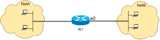
Allow a Select Host to Access the Network
This figure shows a select host is granted permission to access the network. All traffic sourced from Host B destined to NetA is permitted, and all other traffic sourced from NetB destined to NetA is denied.
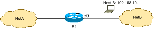
The output on the R1 table shows how the network grants access to the host. This output shows that:
-
The configuration allows only the host with the IP address 192.168.10.1 through the Ethernet 0 interface on R1.
-
This host has access to the IP services of NetA.
-
No other host in NetB has access to NetA.
-
No deny statement is configured in the ACL.
By default, there is an implicit deny all clause at the end of every ACL. Anything that is not explicitly permitted is denied.
R1
hostname R1
!
interface ethernet0
 ip access-group 1 in
!
access-list 1 permit host 192.168.10.1
Note: The ACL filters IP packets from NetB to NetA, except packets sourced from Host B. Packets sourced from Host B to NetA are still permitted.
Note: The ACL access-list 1 permit 192.168.10.1 0.0.0.0 is another way to configure the same rule.
Deny a Select Host to Access the Network
This figure shows that traffic sourced from Host B destined to NetA is denied, while all other traffic from the NetB to access NetA is permitted.
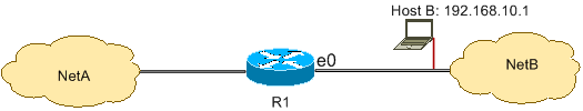
This configuration denies all packets from host 192.168.10.1/32 through Ethernet 0 on R1 and permits everything else. You must use the command access list 1 permit any to explicitly permit everything else because there is an implicit deny all clause with every ACL.
R1
hostname R1
!
interface ethernet0
 ip access-group 1 in
!
access-list 1 deny host 192.168.10.1
access-list 1 permit any
Note: The order of statements is critical to the operation of an ACL. If the order of the entries is reversed as this command shows, the first line matches every packet source address. Therefore, the ACL fails to block host 192.168.10.1/32 from accessing NetA.
access-list 1 permit any
access-list 1 deny host 192.168.10.1
Allow Access to a Range of Contiguous IP Addresses
This figure shows that all hosts in NetB with the network address 192.168.10.0/24 can access network 192.168.200.0/24 in NetA.
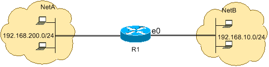
This configuration allows the IP packets with an IP header that has a source address in the network 192.168.10.0/24 and a destination address in the network 192.168.200.0/24 access to NetA. There is the implicit deny all clause at the end of the ACL which denies all other traffic passage through Ethernet 0 inbound on R1.
R1
hostname R1
!
interface ethernet0
 ip access-group 101 in
!
access-list 101 permit ip 192.168.10.0 0.0.0.255 192.168.200.0 0.0.0.255
Note: In the command access-list 101 permit ip 192.168.10.0 0.0.0.255 192.168.200.0 0.0.0.255, the «0.0.0.255» is the inverse mask of network 192.168.10.0 with mask 255.255.255.0. ACLs use the inverse mask to know how many bits in the network address need to match. In the table, the ACL permits all hosts with source addresses in the 192.168.10.0/24 network and destination addresses in the 192.168.200.0/24 network.
Refer to the Masks section of Configuring IP Access Lists for more information on the mask of a network address and how to calculate the inverse mask needed for ACLs.
Deny Telnet Traffic (TCP, Port 23)
In order to meet higher security concerns, you can disable Telnet access to your private network from the public network. This figure shows how Telnet traffic from NetB (public) destined to NetA (private) is denied, which permits NetA to initiate and establish a Telnet session with NetB while all other IP traffic is permitted.

Telnet uses TCP, port 23. This configuration shows that all TCP traffic destined to NetA for port 23 is blocked, and all other IP traffic is permitted.
R1
hostname R1
!
interface ethernet0
 ip access-group 102 in
!
access-list 102 deny tcp any any eq 23
access-list 102 permit ip any any
Allow Only Internal Networks to Initiate a TCP Session
This figure shows that TCP traffic sourced from NetA destined to NetB is permitted, while TCP traffic from NetB destined to NetA is denied.

The purpose of the ACL in this example is to:
-
Allow hosts in NetA to initiate and establish a TCP session to hosts in NetB.
-
Deny hosts in NetB from initiating and establishing a TCP session destined to hosts in NetA.
This configuration allows a datagram to pass through interface Ethernet 0 inbound on R1 when the datagram has:
-
Acknowledged (ACK) or reset (RST) bits set (indicates an established TCP session)
-
A destination port value greater than 1023
R1
hostname R1
!
interface ethernet0
 ip access-group 102 in
!
access-list 102 permit tcp any any gt 1023 established
Since most of the well-known ports for IP services use values less than 1023, any datagram with a destination port less than 1023 or an ACK/RST bit not set is denied by ACL 102. Therefore, when a host from NetB initiates a TCP connection and sends the first TCP packet (without synchronize/start packet (SYN/RST) bit set) for a port number less than 1023, it is denied and the TCP session fails. The TCP sessions initiated from NetA destined to NetB are permitted because they have ACK/RST bit set for returning packets and use port values greater than 1023.
Refer to RFC 1700 for a complete list of ports.
Deny FTP Traffic (TCP, Port 21)
This figure shows that FTP (TCP, port 21) and FTP data (port 20 ) traffic sourced from NetB destined to NetA is denied, while all other IP traffic is permitted.

FTP uses port 21 and port 20. TCP traffic destined to port 21 and port 20 is denied and everything else is explicitly permitted.
R1
hostname R1
!
interface ethernet0
 ip access-group 102 in
!
access-list 102 deny tcp any any eq ftp
access-list 102 deny tcp any any eq ftp-data
access-list 102 permit ip any any
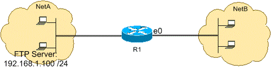
Allow FTP Traffic (Active FTP)
FTP can operate in two different modes named active and passive.
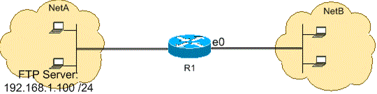
When FTP operates in active mode, the FTP server uses port 21 for control and port 20 for data. FTP server (192.168.1.100) is located in NetA. This figure shows that FTP (TCP, port 21) and FTP data (port 20 ) traffic sourced from NetB destined to FTP server (192.168.1.100) is permitted, while all other IP traffic is denied.
R1
hostname R1
!
interface ethernet0
 ip access-group 102 in
!
access-list 102 permit tcp any host 192.168.1.100 eq ftp
access-list 102 permit tcp any host 192.168.1.100 eq ftp-data established
!
interface ethernet1
 ip access-group 110 in
!
access-list 110 permit host 192.168.1.100 eq ftp any established
access-list 110 permit host 192.168.1.100 eq ftp-data any
Allow FTP Traffic (Passive FTP)
FTP can operate in two different modes named active and passive.
When FTP operates in passive mode, the FTP server uses port 21 for control and the dynamic ports greater than or equal to 1024 for data. FTP server (192.168.1.100) is located in NetA. This figure shows that FTP (TCP, port 21) and FTP data (ports greater than or equal to 1024) traffic sourced from NetB destined to FTP server (192.168.1.100) is permitted, while all other IP traffic is denied.
R1
hostname R1
!
interface ethernet0
 ip access-group 102 in
!
access-list 102 permit tcp any host 192.168.1.100 eq ftp
access-list 102 permit tcp any host 192.168.1.100 gt 1023
!
interface ethernet1
 ip access-group 110 in
!
access-list 110 permit host 192.168.1.100 eq ftp any established
access-list 110 permit host 192.168.1.100 gt 1023 any established
Allow Pings (ICMP)
This figure shows that ICMP sourced from NetA destined to NetB is permitted, and pings sourced from NetB destined to NetA are denied.

This configuration permits only echo-reply (ping response) packets to come in on interface Ethernet 0 from NetB towards NetA. However, the configuration blocks all echo-request ICMP packets when pings are sourced in NetB and destined to NetA. Therefore, hosts in NetA can ping hosts in NetB, but hosts in NetB cannot ping hosts in NetA.
R1
hostname R1
!
interface ethernet0
 ip access-group 102 in
!
access-list 102 permit icmp any any echo-reply
Allow HTTP, Telnet, Mail, POP3, FTP
This figure shows that only HTTP, Telnet, Simple Mail Transfer Protocol (SMTP), POP3, and FTP traffic are permitted, and the rest of the traffic sourced from NetB destined to NetA is denied.
This configuration permits TCP traffic with destination port values that match WWW (port 80), Telnet (port 23), SMTP (port 25), POP3 (port 110), FTP (port 21), or FTP data (port 20). Notice an implicit deny all clause at the end of an ACL denies all other traffic, which does not match the permit clauses.
R1
hostname R1
!
interface ethernet0
 ip access-group 102 in
!
access-list 102 permit tcp any any eq www
access-list 102 permit tcp any any eq telnet
access-list 102 permit tcp any any eq smtp
access-list 102 permit tcp any any eq pop3
access-list 102 permit tcp any any eq 21
access-list 102 permit tcp any any eq 20
Allow DNS
This figure shows that only Domain Name System (DNS) traffic is permitted, and the rest of the traffic sourced from NetB destined to NetA is denied.

This configuration permits TCP traffic with destination port value 53. The implicit deny all clause at the end of an ACL denies all other traffic, which does not match the permit clauses.
R1
hostname R1
!
interface ethernet0
 ip access-group 102 in
!
access-list 102 permit udp any any eq domain
access-list 102 permit udp any eq domain any
access-list 102 permit tcp any any eq domain
access-list 102 permit tcp any eq domain any
Permit Routing Updates
When you apply an in-bound ACL on to an interface, ensure that routing updates are not filtered out. Use the relevant ACL from this list to permit routing protocol packets:
Enter this command in order to permit Routing Information Protocol (RIP):
access-list 102 permit udp any any eq rip
Enter this command in order to permit Interior Gateway Routing Protocol (IGRP):
access-list 102 permit igrp any any
Enter this command in order to permit Enhanced IGRP (EIGRP):
access-list 102 permit eigrp any any
Enter this command in order to permit Open Shortest Path First (OSPF):
access-list 102 permit ospf any any
Enter this command in order to permit Border Gateway Protocol (BGP):
access-list 102 permit tcp any any eq 179
access-list 102 permit tcp any eq 179 any
Debug Traffic Based on ACL
The use of debug commands requires the allocation of system resources like memory and processing power and in extreme situations can cause a heavily-loaded system to stall. Use debug commands with care. Use an ACL in order to selectively define the traffic that needs to be examined to reduce the impact of the debug command. Such a configuration does not filter any packets.
This configuration turns on the debug ip packet command only for packets between the hosts 10.1.1.1 and 172.16.1.1.
R1(config)#access-list 199 permit tcp host 10.1.1.1 host 172.16.1.1
R1(config)#access-list 199 permit tcp host 172.16.1.1 host 10.1.1.1
R1(config)#end

R1#debug ip packet 199 detail
IP packet debugging is on (detailed) for access list 199
Refer to Important Information on Debug Commands for additional information on the impact of debug commands.
Refer to the Use the Debug Command section of Understanding the Ping and Traceroute Commands for additional information on the use of ACLs with debug commands.
MAC Address Filtering
You can filter frames with a particular MAC-layer station source or destination address. Any number of addresses can be configured into the system without a performance penalty. In order to filter by MAC-layer address, use this command in global configuration mode:
Router#config terminal Router(config)#bridge irbRouter(config)#bridge 1 protocol ieeeRouter(config)#bridge 1 route ip
Apply the bridge protocol to an interface that you need to filter traffic along with the access list created with the command bridge-group <group number> {input-address-list <ACL number> | output-address-list <ACL number>}:
Router#config terminalRouter(config-if)#interface fastEthernet0/0Router(config-if)#no ip addressRouter(config-if)#bridge-group 1 input-address-list 700Router(config-if)#exit
Create a Bridged Virtual Interface and apply the IP address that was assigned to the physical Ethernet interface:
Router#config terminalRouter(config-if)#int bvi1Router(config-if)#ip address 192.168.1.1 255.255.255.0Router(config-if)#exitRouter(config)#access-list 700 deny aaaa.bbbb.cccc 0000.0000.0000Router(config)#access-list 700 permit 0000.0000.0000 ffff.ffff.ffff
With this configuration, the router only allows the MAC addresses configured on the access-list 700. With the access list command access-list <ACL number> deny <mac address> 0000.0000.0000, deny the MAC address that cannot have access and then permit the rest (for this example, aaaa.bbbb.cccc).
Note: Create every line of access list for each MAC address.
Verify
There is currently no verification procedure available for this configuration.
Troubleshoot
There is currently no specific information available to troubleshoot this configuration.
Related Information
- Configuring IP Access Lists
- Access Lists Support Page
- IP Routing Support Page
- IP Routed Protocols Support Page
- Technical Support & Documentation — Cisco Systems
Время на прочтение
9 мин
Количество просмотров 526K
Сегодня я расскажу вам о том, как отфильтровать трафик в сети с помощью списков контроля доступа. Рассмотрим как они работают соответственно, что собой представляют, для чего предназначены. Позже я покажу как они настраиваются в Cisco IOS и выложу архив с лабораторными работами для закрепления ваших знаний.
Введение
ACL (Access Control List) — это набор текстовых выражений, которые что-то разрешают, либо что-то запрещают. Обычно ACL разрешает или запрещает IP-пакеты, но помимо всего прочего он может заглядывать внутрь IP-пакета, просматривать тип пакета, TCP и UDP порты. Также ACL существует для различных сетевых протоколов (IP, IPX, AppleTalk и так далее). В основном применение списков доступа рассматривают с точки зрения пакетной фильтрации, то есть пакетная фильтрация необходима в тех ситуациях, когда у вас стоит оборудование на границе Интернет и вашей частной сети и нужно отфильтровать ненужный трафик.
Вы размещаете ACL на входящем направлении и блокируете избыточные виды трафика.
Теория
Функционал ACL состоит в классификации трафика, нужно его проверить сначала, а потом что-то с ним сделать в зависимости от того, куда ACL применяется. ACL применяется везде, например:
- На интерфейсе: пакетная фильтрация
- На линии Telnet: ограничения доступа к маршрутизатору
- VPN: какой трафик нужно шифровать
- QoS: какой трафик обрабатывать приоритетнее
- NAT: какие адреса транслировать
Для применения ACL для всех этих компонентов нужно понять как они работают. И мы в первую очередь будем касаться пакетной фильтрации. Применительно к пакетной фильтрации, ACL размещаются на интерфейсах, сами они создаются независимо, а уже потом они прикручиваются к интерфейсу. Как только вы его прикрутили к интерфейсу маршрутизатор начинает просматривать трафик. Маршрутизатор рассматривает трафик как входящий и исходящий. Тот трафик, который входит в маршрутизатор называется входящим, тот который из него выходит — исходящий. Соответственно ACL размещаются на входящем или на исходящем направлении.

Из вашей частной сети приходит пакет на интерфейс маршрутизатора fa0/1, маршрутизатор проверяет есть ли ACL на интерфейсе или нет, если он есть, то дальше обработка ведется по правилам списка доступа строго в том порядке, в котором записаны выражения, если список доступа разрешает проходить пакету, то в данном случае маршрутизатор отправляет пакет провайдеру через интерфейс fa0/0, если список доступа не разрешает проходить пакету, пакет уничтожается. Если списка доступа нет — пакет пролетает без всяких ограничений. Перед тем как отправить пакет провайдеру, маршрутизатор ещё проверяет интерфейс fa0/0 на наличие исходящего ACL. Дело в том, что ACL может быть прикреплен на интерфейсе как входящий или исходящий. К примеру у нас есть ACL с правилом запретить всем узлам в Интернете посылать в нашу сеть пакеты.
Так на какой интерфейс прикрепить данную ACL? Если мы прикрепим ACL на интерфейс fa0/1 как исходящий, это будет не совсем верно, хотя и ACL работать будет. На маршрутизатор приходит эхо-запрос для какого-то узла в частной сети, он проверяет на интерфейсе fa0/0 есть ли ACL, его нет, дальше проверяет интерфейс fa0/1, на данном интерфейсе есть ACL, он настроен как исходящий, всё верно пакет не проникает в сеть, а уничтожается маршрутизатором. Но если мы прикрепим ACL за интерфейсом fa0/0 как входящий, то пакет будет уничтожатся сразу как пришел на маршрутизатор. Последнее решение является правильным, так как маршрутизатор меньше нагружает свои вычислительные ресурсы. Расширенные ACL нужно размещать как можно ближе к источнику, стандартные же как можно ближе к получателю. Это нужно для того, чтобы не гонять пакеты по всей сети зря.
Сам же ACL представляет собой набор текстовых выражений, в которых написано permit (разрешить) либо deny (запретить), и обработка ведется строго в том порядке в котором заданы выражения. Соответственно когда пакет попадает на интерфейс он проверяется на первое условие, если первое условие совпадает с пакетом, дальнейшая его обработка прекращается. Пакет либо перейдет дальше, либо уничтожится.
Ещё раз, если пакет совпал с условием, дальше он не обрабатывается. Если первое условие не совпало, идет обработка второго условия, если оно совпало, обработка прекращается, если нет, идет обработка третьего условия и так дальше пока не проверятся все условия, если никакое из условий не совпадает, пакет просто уничтожается. Помните, в каждом конце списка стоит неявный deny any (запретить весь трафик). Будьте очень внимательны с этими правилами, которые я выделил, потому что очень часто происходят ошибки при конфигурации.
ACL разделяются на два типа:
- Стандартные (Standard): могут проверять только адреса источников
- Расширенные (Extended): могут проверять адреса источников, а также адреса получателей, в случае IP ещё тип протокола и TCP/UDP порты
Обозначаются списки доступа либо номерами, либо символьными именами. ACL также используются для разных сетевых протоколов. Мы в свою очередь будем работать с IP. Обозначаются они следующим образом, нумерованные списки доступа:
- Стандартные: от 1 до 99
- Расширенные: от 100 до 199
Символьные ACL разделяются тоже на стандартные и расширенные. Расширенные напомню могут проверять гораздо больше, нежели стандартные, но и работают они медленнее, так как придется заглядывать внутрь пакета, в отличии от стандартных где мы смотрим только поле Source Address (Адрес отправителя). При создании ACL каждая запись списка доступа обозначается порядковым номером, по умолчанию в рамках десяти (10, 20, 30 и т.д). Благодаря чему, можно удалить конкретную запись и на её место вставить другую, но эта возможность появилась в Cisco IOS 12.3, до 12.3 приходилось ACL удалять, а потом создать заново полностью. Нельзя разместить более 1 списка доступа на интерфейс, на протокол, на направление. Объясняю: если у нас есть маршрутизатор и у него есть интерфейс, мы можем на входящее направление для IP-протокола разместить только один список доступа, например под номером 10. Ещё одно правило, касающееся самих маршрутизаторов, ACL не действует на трафик, сгенерированный самим маршрутизатором.
Для фильтрации адресов в ACL используется WildCard-маска. Это обратная маска. Берем шаблонное выражение: 255.255.255.255 и отнимаем от шаблона обычную маску.
255.255.255.255-255.255.255.0, у нас получается маска 0.0.0.255, что является обычной маски 255.255.255.0, только 0.0.0.255 является WildCard маской.
Виды ACL
Динамический (Dynamic ACL)
Позволяет сделать следующее, например у вас есть маршрутизатор, который подключен к какому-то серверу и нам нужно закрыть доступ к нему из внешнего мира, но в тоже время есть несколько человек, которые могут подключаться к серверу.
Мы настраиваем динамический список доступа, прикрепляем его на входящем направлении, а дальше людям, которым нужно подключиться, подключаться через Telnet к данному устройству, в результате динамический ACL открывает проход к серверу, и уже человек может зайти скажем через HTTP попасть на сервер. По умолчанию через 10 минут этот проход закрывается и пользователь вынужден ещё раз выполнить Telnet чтобы подключиться к устройству.
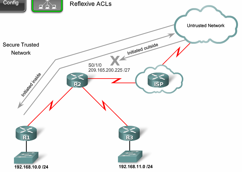
Рефлексивный (Reflexive ACL)
Здесь ситуация немножко отличается, когда узел в локальной сети отправляет TCP запрос в Интернет, у нас должен быть открытый проход, чтобы пришел TCP ответ для установки соединения. Если прохода не будет — мы не сможем установить соединение, и вот этим проходом могут воспользоваться злоумышленники, например проникнуть в сеть. Рефлексивные ACL работают таким образом, блокируется полностью доступ (deny any) но формируется ещё один специальный ACL, который может читать параметры пользовательских сессий, которые сгенерированны из локальной сети и для них открывать проход в deny any, в результате получается что из Интернета не смогут установить соединение. А на сессии сгенерированны из локальной сети будут приходить ответы.
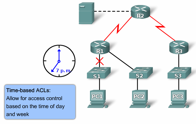
Ограничение по времени (Time-based ACL)
Обычный ACL, но с ограничением по времени, вы можете ввести специальное расписание, которое активирует ту или иную запись списка доступа. И сделать такой фокус, например пишем список доступа, в котором запрещаем HTTP-доступ в течении рабочего дня и вешаем его на интерфейс маршрутизатора, то есть, сотрудники предприятия пришли на работу, им закрывается HTTP-доступ, рабочий день закончился, HTTP-доступ открывается,
пожалуйста, если хотите — сидите в Интернете.
Настройка
Сами ACL создаются отдельно, то есть это просто некий список, который создается в глобальном конфиге, потом он присваивается к интерфейсу и только тогда он и начинает работать. Необходимо помнить некоторые моменты, для того, чтобы правильно настроить списки доступа:
- Обработка ведется строго в том порядке, в котором записаны условия
- Если пакет совпал с условием, дальше он не обрабатывается
- В конце каждого списка доступа стоит неявный deny any (запретить всё)
- Расширенные ACL нужно размещать как можно ближе к источнику, стандартные же как можно ближе к получателю
- Нельзя разместить более 1 списка доступа на интерфейс, на протокол, на направление
- ACL не действует на трафик, сгенерированный самим маршрутизатором
- Для фильтрации адресов используется WildCard маска
Стандартный список доступа
Router(config)#access-list <номер списка от 1 до 99> {permit | deny | remark} {address | any | host} [source-wildcard] [log]
- permit: разрешить
- deny: запретить
- remark: комментарий о списке доступа
- address: запрещаем или разрешаем сеть
- any: разрешаем или запрещаем всё
- host: разрешаем или запрещаем хосту
- source-wildcard: WildCard маска сети
- log: включаем логгирование пакеты проходящие через данную запись ACL
Расширенный список доступа
Router(config)#access-list <номер списка от 100 до 199> {permit | deny | remark} protocol source [source-wildcard] [operator operand] [port <порт или название протокола> [established]
- protocol source: какой протокол будем разрешать или закрывать (ICMP, TCP, UDP, IP, OSPF и т.д)
- deny: запретить
- operator:
A.B.C.D — адрес получателя
any — любой конечный хост
eq — только пакеты на этом порте
gt — только пакеты с большим номером порта
host — единственный конечный хост
lt — только пакеты с более низким номером порта
neq — только пакеты не на данном номере порта
range — диапазон портов - port: номер порта (TCP или UDP), можно указать имя
- established: разрешаем прохождение TCP-сегментов, которые являются частью уже созданной TCP-сессии
Прикрепляем к интерфейсу
Router(config-if)#ip access-group <номер списка или имя ACL> {in | out}
- in: входящее направление
- out: исходящее направление
Именованные списки доступа
Router(config)#ip access-list {standard | extended} {<номер ACL> | <имя ACL>}
Router(config-ext-nacl)# {default | deny | exit | no | permit | remark}
- standard: стандартный ACL
- extended: расширенный ACL
- default: установить команду в значение по умолчанию
Ограничение доступа к маршрутизатору
R(config)#line vty 0 4 — переходим в режим настройки виртуальных линий.
R(config-line)#password <пароль> — настраиваем логин и пароль, а также закрепляем список доступа с разрешенными IP-адресами.
R(config-line)#login
R(config-line)#access-class 21 in
Динамические списки доступа

R3(config)#username Student password 0 cisco — создаем пользователей для подключения через Telnet.
R3(config)#access-list 101 permit tcp any host 10.2.2.2 eq telnet
R3(config)#access-list 101 dynamic testlist timeout 15 permit ip 192.168.10.0 0.0.0.255 192.168.30.0 0.0.0.255 — разрешаем подключаться к серверу по Telnet всем узлам.
R3(config)#interface serial 0/0/1 — закрепляем 101 ACL за интерфейсом в входящем направлении.
R3(config-if)#ip access-group 101 in
R3(config)#line vty 0 4 — как только пользователь аутентифицируеться, сеть 192.168.30.0 будет доступна, через 5 минут бездействия сеанс закроется.
R3(config-line)#login local
R3(config-line)#autocommand access-enable host timeout 5
Рефлексивные списки доступа
R2(config)#ip access-list extended OUTBOUNDFILTERS — заставляем маршрутизатор отслеживать трафик, который инициировался изнутри.
R2(config-ext-nacl)#permit tcp 192.168.0.0 0.0.255.255 any reflect TCPTRAFFIC
R2(config-ext-nacl)#permit icmp 192.168.0.0 0.0.255.255 any reflect ICMPTRAFFIC
R2(config)#ip access-list extended INBOUNDFILTERS — создаем входящую политику, которая требует, чтобы маршрутизатор проверял входящий трафик, чтобы видеть инициировался ли изнутри и связываем TCPTRAFFIC к INBOUNDFILTERS.
R2(config-ext-nacl)#evaluate TCPTRAFFIC
R2(config-ext-nacl)#evaluate ICMPTRAFFIC
R2(config)#interface serial 0/1/0 — применяем входящий и исходящий ACL на интерфейс.
R2(config-if)#ip access-group INBOUNDFILTERS in
R2(config-if)#ip access-group OUTBOUNDFILTERS out
Ограничение по времени
R1(config)#time-range EVERYOTHERDAY — создаем список времени, в котором добавляем дни недели и время.
R1(config-time-range)#periodic Monday Wednesday Friday 8:00 to 17:00
R1(config)#access-list 101 permit tcp 192.168.10.0 0.0.0.255 any eq telnet time-range EVERYOTHERDAY — применяем time-range к ACL.
R1(config)#interface s0/0/0 — закрепляем ACL за интерфейсом.
R1(config-if)#ip access-group 101 out
Поиск проблем
R#show access-lists {ACL номер | имя} — смотрим информацию о списке доступа.
R#show access-lists — смотрим все списки доступа на маршрутизаторе.
Пример
Router#show access-lists

Extended IP access list nick

permit ip host 172.168.1.1 host 10.0.0.5

 deny ip any any (16 match(es))

Standard IP access list nick5

 permit 172.16.0.0 0.0.255.255
Мы видим что у нас есть два ACL (стандартный и расширенный) под названиями nick и nick5. Первый список разрешает хосту 172.16.1.1 обращаться по IP (это значит что разрешены все протоколы работающие поверх IP) к хосту 10.0.0.5. Весь остальной трафик запрещен показывает команда deny ip any any. Рядом с этим условием в нашем примере пишет (16 match(es)). Это показывает что 16 пакетов попали под это условие.
Второй ACL разрешает проходить трафик от любого источника в сети 172.16.0.0/16.
Практика
Я собрал лабораторные работы для Packet Tracer с 5 главы курса CCNA 4 по теме ACL. Если у вас есть желание закрепить знания на практике, пожалуйста — ссылка, зеркало — FTP. Размер — 865.14 KB.
Литература
CCNA Exploration: Accessing the WAN (5 chapter)
Configuring ACL
CHAPTERS
1. Overview
2. ACL Configuration
3. Configuration Example for ACL
4. Appendix: Default Parameters
|
|
This guide applies to: T1500G-8T v2 or above, T1500G-10PS v2 or above, T1500G-10MPS v2 or above, T1500-28PCT v3 or above, T1600G-18TS v2 or above, T1600G-28PS v3 or above, T1600G-28TS v3 or above, T1600G-52TS v3 or above, T1600G-52PS v3 or above, T1700X-16TS v3 or above, T1700G-28TQ v3 or above, T2500G-10TS v2 or above, T2600G-18TS v2 or above, T2600G-28TS v3 or above, T2600G-28MPS v3 or above, T2600G-28SQ v1 or above, T2600G-52TS v3 or above. |
1Overview
ACL (Access Control List) filters traffic as it passes through a switch, and permits or denies packets crossing specified interfaces or VLANs. It accurately identifies and processes the packets based on the ACL rules. In this way, ACL helps to limit network traffic, manage network access behaviors, forward packets to specified ports and more.
To configure ACL, follow these steps:
1)Configure a time range during which the ACL is in effect.
2)Create an ACL and configure the rules to filter different packets.
3)Bind the ACL to a port or VLAN to make it effective.
Configuration Guidelines
A packet “matches” an ACL rule when it meets the rule’s matching criteria. The resulting action will be either to “permit” or “deny” the packet that matches the rule.
If no ACL rule is configured, the packets will be forwarded without being processed by the ACL. If there is configured ACL rules and no matching rule is found, the packets will be dropped.
2ACL Configuration
2.1Using the GUI
2.1.1Configuring Time Range
Some ACL-based services or features may need to be limited to take effect only during a specified time period. In this case, you can configure a time range for the ACL. For details about Time Range configuration, please refer to Managing System.
2.1.2Creating an ACL
You can create different types of ACL and define the rules based on source MAC or IP address, destination MAC or IP address, protocol type, port number and so on.
MAC ACL: MAC ACL uses source and destination MAC address for matching operations.
IP ACL: IP ACL uses source and destination IP address, IP protocols and so on for matching operations.
Combined ACL: Combined ACL uses source and destination MAC address, and source and destination IP address for matching operations.
IPv6 ACL: IPv6 ACL uses source and destination IPv6 address for matching operations.
Packet Content ACL: Packet Content ACL analyzes and processes data packets based on 4 chunk match conditions, each chunk can specify a user-defined 4-byte segment carried in the packet’s first 128 bytes. Only T2600G series support this feature.
Choose the menu SECURITY > ACL > ACL Config and click to load the following page.
Figure 2-1 Creating an ACL
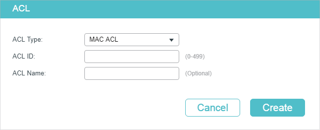
Follow these steps to create an ACL:
1)Choose one ACL type and enter a number to identify the ACL.
2)(Optional) Assign a name to the ACL.
3)Click Create.
|
|
Note: The supported ACL type and ID range varies on different switch models. Please refer to the on-screen information. |
2.1.3Configuring ACL Rules
|
|
Note: Every ACL has an implicit deny all rule at the end of an ACL rule list. That is, if an ACL is applied to a packet and none of the explicit rules match, then the final implicit deny all rule takes effect and the packet is dropped. |
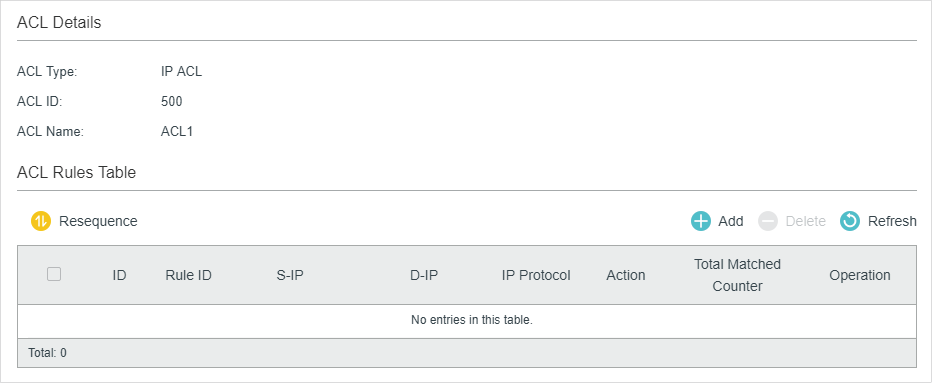
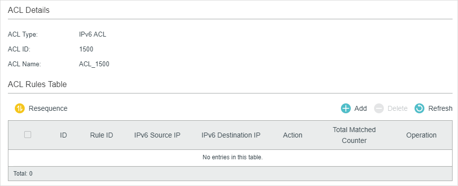
The created ACL will be displayed on the SECURITY > ACL > ACL Config page.
Figure 2-2 Editing ACL
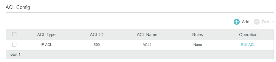
Click Edit ACL in the Operation column. Then you can configure rules for this ACL.
The following sections introduce how to configure MAC ACL, IP ACL, Combined ACL, IPv6 ACL and Packet Content ACL.
Configuring MAC ACL Rule
Click Edit ACL for a MAC ACL entry to load the following page.
Figure 2-3 Configuring the MAC ACL Rule
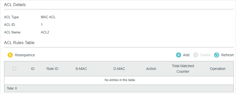
In ACL Rules Table section, click and the following page will appear.
Figure 2-4 Configuring the MAC ACL Rule
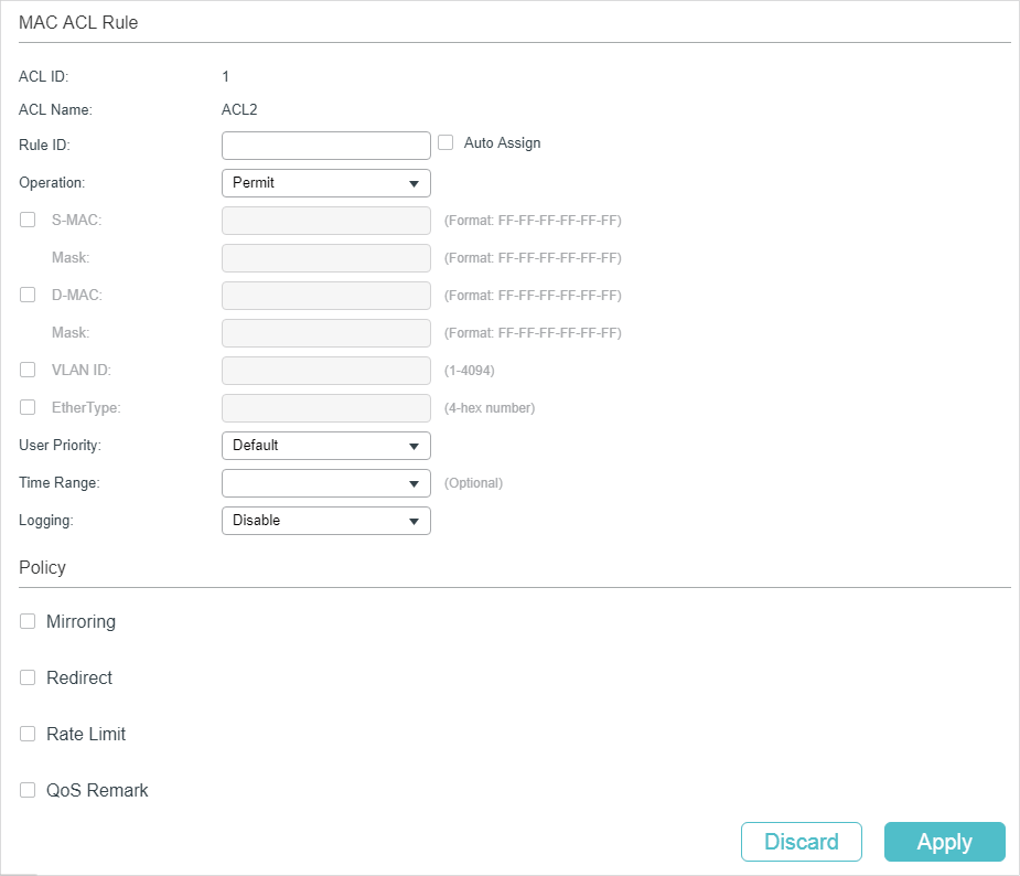
Follow these steps to configure the MAC ACL rule:
1)In the MAC ACL Rule section, configure the following parameters:
|
Rule ID |
Enter an ID number to identify the rule. It should not be the same as any current rule ID in the same ACL. For the convenience of inserting new rules to an ACL, you should set the appropriate interval between rule IDs. If you select Auto Assign, the rule ID will be assigned automatically by the system and the default increment between neighboring rule IDs is 5. |
|
Operation |
Select an action to be taken when a packet matches the rule. Permit: To forward the matched packets. Deny: To discard the matched packets. |
|
S-MAC/Mask |
Enter the source MAC address with a mask. A value of 1 in the mask indicates that the corresponding bit in the address will be matched. |
|
D-MAC/Mask |
Enter the destination MAC address with a mask. A value of 1 in the mask indicates that the corresponding bit in the address will be matched. |
|
VLAN ID |
Enter the ID number of the VLAN with which packets will match. The valid range is 1-4094. If the ACL is bound to a VLAN, the system requires the VLAN ID of a packet to match the ID of the VLAN instead of the ID listed here. |
|
EtherType |
Specify the EtherType to be matched using 4 hexadecimal numbers. |
|
User Priority |
Specify the User Priority to be matched. |
|
Time Range |
Select a time range during which the rule will take effect. The default value is No Limit, which means the rule is always in effect. The Time Range referenced here can be created on the SYSTEM > Time Range page. |
|
Logging |
Enable Logging function for the ACL rule. Then the times that the rule is matched will be logged every 5 minutes and a related trap will be generated. You can refer to Total Matched Counter in the ACL Rules Table to view the matching times. |
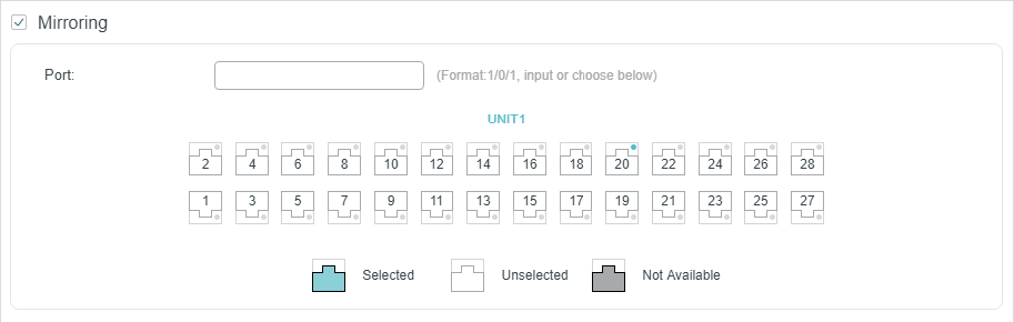
2)In the Policy section, enable or disable the Mirroring feature for the matched packets. With this option enabled, choose a destination port to which the packets will be mirrored.
Figure 2-5 Configuring Mirroring
3)In the Policy section, enable or disable the Redirect feature for the matched packets. With this option enabled, choose a destination port to which the packets will be redirected.
Figure 2-6 Configuring Redirect
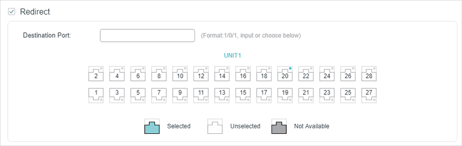
|
|
Note: In the Mirroring feature, the matched packets will be copied to the destination port and the original forwarding will not be affected. While in the Redirect feature, the matched packets will be forwarded only on the destination port. |
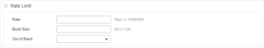
4)In the Policy section, enable or disable the Rate Limit feature for the matched packets. With this option enabled, configure the related parameters.
Figure 2-7 Configuring Rate Limit
|
Rate |
Specify the transmission rate for the matched packets. |
|
Burst Size |
Specify the maximum number of bytes allowed in one second. |
|
Out of Band |
Select the action for the packets whose rate is beyond the specified rate. None: The packets will be forwarded normally. Drop: The packets will be discarded. Remark DSCP: You can specify a DSCP value, and the DSCP field of the packets will be changed to the specified one. T1500 series, T1600G-18TS, T1600G-28TS, T1600G-28PS, T1600G-52TS v4 and T1600G-52PS v4 do not support this option. |
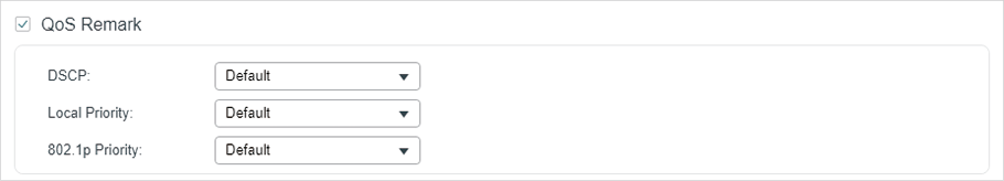
5)In the Policy section, enable or disable the QoS Remark feature for the matched packets. With this option enabled, configure the related parameters, and the remarked values will take effect in the QoS processing on the switch.
Figure 2-8 Configuring QoS Remark
|
DSCP |
Specify the DSCP field for the matched packets. The DSCP field of the packets will be changed to the specified one. |
|
Local Priority |
Specify the local priority for the matched packets. The local priority of the packets will be changed to the specified one. |
|
802.1p Priority |
Specify the 802.1p priority for the matched packets. The 802.1p priority of the packets will be changed to the specified one. |
6)Click Apply.
Configuring IP ACL Rule
Click Edit ACL for an IP ACL entry to load the following page.
Figure 2-9 Configuring the IP ACL Rule
In ACL Rules Table section, click and the following page will appear.
Figure 2-10 Configuring the IP ACL Rule
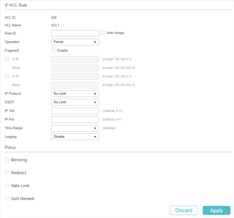
Follow these steps to configure the IP ACL rule:
1)In the IP ACL Rule section, configure the following parameters:
|
Rule ID |
Enter an ID number to identify the rule. It should not be the same as any current rule ID in the same ACL. For the convenience of inserting new rules to an ACL, you should set the appropriate interval between rule IDs. If you select Auto Assign, the rule ID will be assigned automatically by the system and the default increment between neighboring rule IDs is 5 |
|
Operation |
Select an action to be taken when a packet matches the rule. Permit: To forward the matched packets. Deny: To discard the matched packets. |
|
Fragment |
With this option selected, the rule will be applied to all fragment packets except for the last fragment packet in the fragment packet group. T1500 series, T1600G-18TS, T1600G-28TS, T1600G-28PS, T1600G-52TS v4 and T1600G-52PS v4 do not support this option. |
|
S-IP/Mask |
Enter the source IP address with a mask. A value of 1 in the mask indicates that the corresponding bit in the address will be matched. |
|
D-IP/Mask |
Enter the destination IP address with a mask. A value of 1 in the mask indicates that the corresponding bit in the address will be matched. |
|
IP Protocol |
Select a protocol type from the drop-down list. The default is No Limit, which indicates that packets of all protocols will be matched. You can also select User-defined to customize the IP protocol. |
|
TCP Flag |
If TCP protocol is selected, you can configure the TCP Flag to be used for the rule’s matching operations. There are six flags and each has three options, which are *, 0 and 1. The default is *, which indicates that the flag is not used for matching operations. URG: Urgent flag. ACK: Acknowledge flag. PSH: Push flag. RST: Reset flag. SYN: Synchronize flag. FIN: Finish flag. |
|
S-Port / D-Port |
If TCP/UDP is selected as the IP protocol, specify the source and destination port number with a mask. Value: Specify the port number. Mask: Specify the port mask with 4 hexadacimal numbers. |
|
DSCP |
Specify a DSCP value to be matched between 0 and 63. The default is No Limit. |
|
IP ToS |
Specify an IP ToS value to be matched between 0 and 15. The default is No Limit. |
|
IP Pre |
Specify an IP Precedence value to be matched to be matched between 0 and 7. The default is No Limit. |
|
Time Range |
Select a time range during which the rule will take effect. The default value is No Limit, which means the rule is always in effect. The Time Range referenced here can be created on the SYSTEM > Time Range page. |
|
Logging |
Enable Logging function for the ACL rule. Then the times that the rule is matched will be logged every 5 minutes and a related trap will be generated. You can refer to Total Matched Counter in the ACL Rules Table to view the matching times. |
2)In the Policy section, enable or disable the Mirroring feature for the matched packets. With this option enabled, choose a destination port to which the packets will be mirrored.
Figure 2-11 Configuring Mirroring
3)In the Policy section, enable or disable the Redirect feature for the matched packets. With this option enabled, choose a destination port to which the packets will be redirected.
Figure 2-12 Configuring Redirect
|
|
Note: In the Mirroring feature, the matched packets will be copied to the destination port and the original forwarding will not be affected. While in the Redirect feature, the matched packets will be forwarded only on the destination port. |
4)In the Policy section, enable or disable the Rate Limit feature for the matched packets. With this option enabled, configure the related parameters.
Figure 2-13 Configuring Rate Limit
|
Rate |
Specify the transmission rate for the matched packets. |
|
Burst Size |
Specify the maximum number of bytes allowed in one second. |
|
Out of Band |
Select the action for the packets whose rate is beyond the specified rate. None: The packets will be forwarded normally. Drop: The packets will be discarded. Remark DSCP: You can specify a DSCP value, and the DSCP field of the packets will be changed to the specified one. T1500 series, T1600G-18TS, T1600G-28TS, T1600G-28PS, T1600G-52TS v4 and T1600G-52PS v4 do not support this option. |
5)In the Policy section, enable or disable the QoS Remark feature for the matched packets. With this option enabled, configure the related parameters, and the remarked values will take effect in the QoS processing on the switch.
Figure 2-14 Configuring QoS Remark
|
DSCP |
Specify the DSCP field for the matched packets. The DSCP field of the packets will be changed to the specified one. |
|
Local Priority |
Specify the local priority for the matched packets. The local priority of the packets will be changed to the specified one. |
|
802.1p Priority |
Specify the 802.1p priority for the matched packets. The 802.1p priority of the packets will be changed to the specified one. |
6)Click Apply.
Configuring Combined ACL Rule
Click Edit ACL for a Combined ACL entry to load the following page.
Figure 2-15 Configuring the Combined ACL Rule
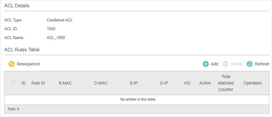
In ACL Rules Table section, click and the following page will appear.
Figure 2-16 Configuring the Combined ACL Rule
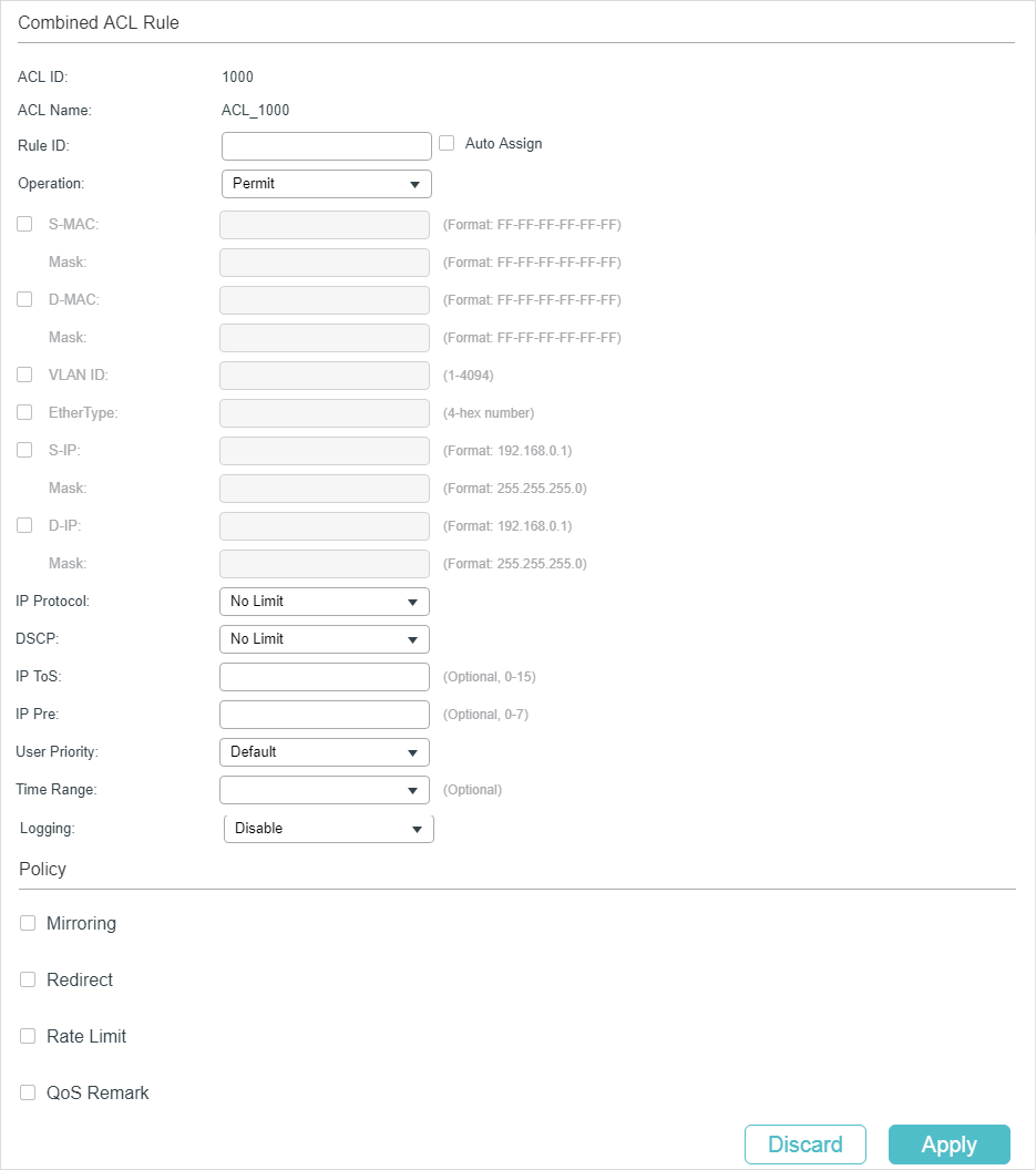
Follow these steps to configure the Combined ACL rule:
1)In the Combined ACL Rule section, configure the following parameters:
|
Rule ID |
Enter an ID number to identify the rule. It should not be the same as any current rule ID in the same ACL. For the convenience of inserting new rules to an ACL, you should set the appropriate interval between rule IDs. If you select Auto Assign, the rule ID will be assigned automatically by the system and the default increment between neighboring rule IDs is 5 |
|
Operation |
Select an action to be taken when a packet matches the rule. Permit: To forward the matched packets. Deny: To discard the matched packets. |
|
S-MAC/Mask |
Enter the source MAC address with a mask. A value of 1 in the mask indicates that the corresponding bit in the address will be matched. |
|
D-MAC/Mask |
Enter the destination IP address with a mask. A value of 1 in the mask indicates that the corresponding bit in the address will be matched. |
|
VLAN ID |
Enter the ID number of the VLAN with which packets will match. The valid range is 1-4094. If the ACL is bound to a VLAN, the system requires the VLAN ID of a packet to match the ID of the VLAN instead of the ID listed here. |
|
EtherType |
Specify the EtherType to be matched using 4 hexadecimal numbers. |
|
S-IP/Mask |
Enter the source IP address with a mask. A value of 1 in the mask indicates that the corresponding bit in the address will be matched. |
|
D-IP/Mask |
Enter the destination IP address with a mask. A value of 1 in the mask indicates that the corresponding bit in the address will be matched. |
|
IP Protocol |
Select a protocol type from the drop-down list. The default is No Limit, which indicates that packets of all protocols will be matched. You can also select User-defined to customize the IP protocol. |
|
TCP Flag |
If TCP protocol is selected, you can configure the TCP Flag to be used for the rule’s matching operations. There are six flags and each has three options, which are *, 0 and 1. The default is *, which indicates that the flag is not used for matching operations. URG: Urgent flag. ACK: Acknowledge flag. PSH: Push flag. RST: Reset flag. SYN: Synchronize flag. FIN: Finish flag. |
|
S-Port / D-Port |
If TCP/UDP is selected as the IP protocol, specify the source and destination port number with a mask. Value: Specify the port number. Mask: Specify the port mask with 4 hexadacimal numbers. |
|
DSCP |
Specify a DSCP value to be matched between 0 and 63. The default is No Limit. |
|
IP ToS |
Specify an IP ToS value to be matched between 0 and 15. The default is No Limit. |
|
IP Pre |
Specify an IP Precedence value to be matched to be matched between 0 and 7. The default is No Limit. |
|
User Priority |
Specify the User Priority to be matched. |
|
Time Range |
Select a time range during which the rule will take effect. The default value is No Limit, which means the rule is always in effect. The Time Range referenced here can be created on the SYSTEM > Time Range page. |
|
Logging |
Enable Logging function for the ACL rule. Then the times that the rule is matched will be logged every 5 minutes and a related trap will be generated. You can refer to Total Matched Counter in the ACL Rules Table to view the matching times. |
2)In the Policy section, enable or disable the Mirroring feature for the matched packets. With this option enabled, choose a destination port to which the packets will be mirrored.
Figure 2-17 Configuring Mirroring
3)In the Policy section, enable or disable the Redirect feature for the matched packets. With this option enabled, choose a destination port to which the packets will be redirected.
Figure 2-18 Configuring Redirect
|
|
Note: In the Mirroring feature, the matched packets will be copied to the destination port and the original forwarding will not be affected. While in the Redirect feature, the matched packets will be forwarded only on the destination port. |
4)In the Policy section, enable or disable the Rate Limit feature for the matched packets. With this option enabled, configure the related parameters.
Figure 2-19 Configuring Rate Limit
|
Rate |
Specify the transmission rate for the matched packets. |
|
Burst Size |
Specify the maximum number of bytes allowed in one second. |
|
Out of Band |
Select the action for the packets whose rate is beyond the specified rate. None: The packets will be forwarded normally. Drop: The packets will be discarded. Remark DSCP: You can specify a DSCP value, and the DSCP field of the packets will be changed to the specified one. T1500 series, T1600G-18TS, T1600G-28TS, T1600G-28PS, T1600G-52TS v4 and T1600G-52PS v4 do not support this option. |
5)In the Policy section, enable or disable the QoS Remark feature for the matched packets. With this option enabled, configure the related parameters, and the remarked values will take effect in the QoS processing on the switch.
Figure 2-20 Configuring QoS Remark
|
DSCP |
Specify the DSCP field for the matched packets. The DSCP field of the packets will be changed to the specified one. |
|
Local Priority |
Specify the local priority for the matched packets. The local priority of the packets will be changed to the specified one. |
|
802.1p Priority |
Specify the 802.1p priority for the matched packets. The 802.1p priority of the packets will be changed to the specified one. |
6)Click Apply.
Configuring the IPv6 ACL Rule
Click Edit ACL for an IPv6 ACL entry to load the following page.
Figure 2-21 Configuring the IPv6 ACL Rule
In ACL Rules Table section, click and the following page will appear.
Figure 2-22 Configuring the IPv6 ACL Rule
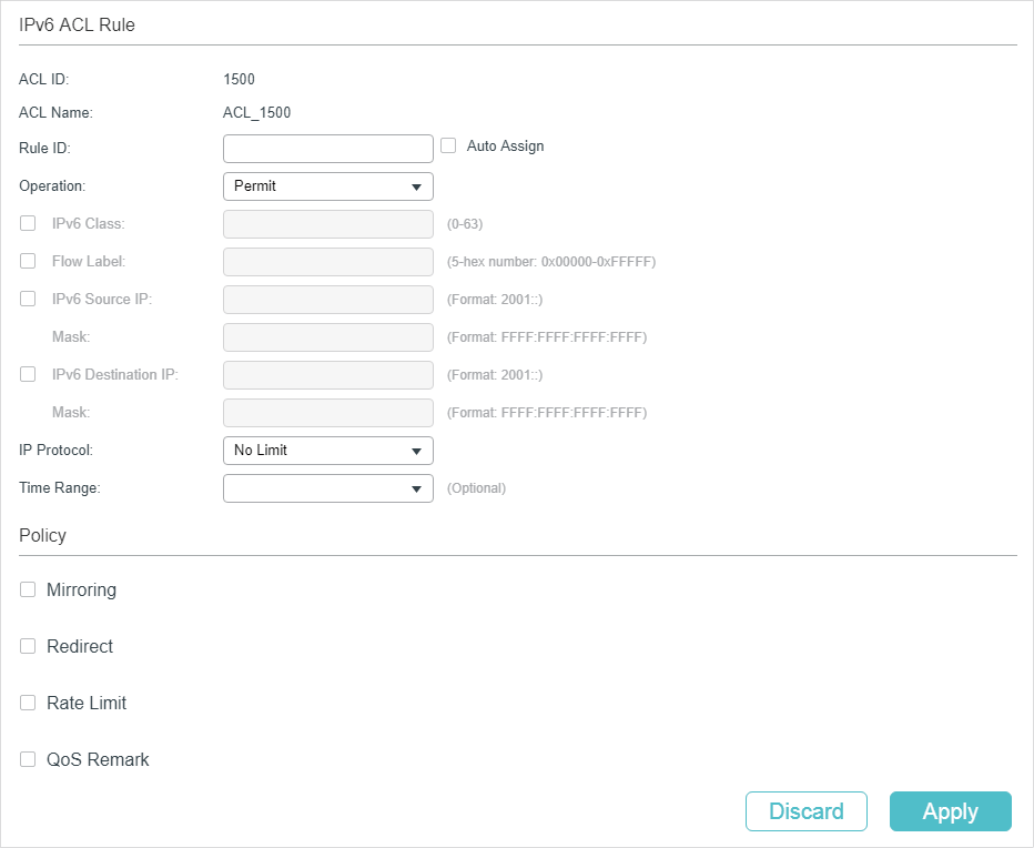
Follow these steps to configure the IPv6 ACL rule:
1)In the IPv6 ACL Rule section, configure the following parameters:
|
Rule ID |
Enter an ID number to identify the rule. It should not be the same as any current rule ID in the same ACL. For the convenience of inserting new rules to an ACL, you should set the appropriate interval between rule IDs. If you select Auto Assign, the rule ID will be assigned automatically by the system and the default increment between neighboring rule IDs is 5 |
|
Operation |
Select an action to be taken when a packet matches the rule. Permit: To forward the matched packets. Deny: To discard the matched packets. |
|
IPv6 Class |
Specify an IPv6 class value to be matched. The switch will check the class field of the IPv6 header. |
|
Flow Label |
Specify a Flow Label value to be matched. |
|
IPv6 Source IP |
Enter the source IPv6 address to be matched. All types of IPv6 address will be checked. You may enter a complete 128-bit IPv6 address but only the first 64 bits will be valid. |
|
Mask |
The mask is required if the source IPv6 address is entered. Enter the mask in complete format (for example, FFFF:FFFF:0000:FFFF). The IP address mask specifies which bits in the source IPv6 address to match the rule. A value of 1 in the mask indicates that the corresponding bit in the address will be matched. |
|
IPv6 Destination IP |
Enter the destination IPv6 address to be matched. All types of IPv6 address will be checked. You may enter a complete 128-bit IPv6 address but only the first 64 bits will be valid. |
|
Mask |
The mask is required if the destination IPv6 address is entered. Enter the complete mask (for example, FFFF:FFFF:0000:FFFF). The IP address mask specifies which bits in the source IP address to match the rule. A value of 1 in the mask indicates that the corresponding bit in the address will be matched. |
|
IP Protocol |
Select a protocol type from the drop-down list. No Limit: Packets of all protocols will be matched. UDP: Specify the source port and destination port for the UDP packet to be matched. TCP: Specify the source port and destination port for the TCP packet to be matched. User-defined: You can customize an IP protocol. |
|
S-Port / D-Port |
If TCP/UDP is selected as the IP protocol, specify the source and destination port numbers. |
|
Time Range |
Select a time range during which the rule will take effect. The default value is No Limit, which means the rule is always in effect. The Time Range referenced here can be created on the SYSTEM > Time Range page. |
2)In the Policy section, enable or disable the Mirroring feature for the matched packets. With this option enabled, choose a destination port to which the packets will be mirrored.
Figure 2-23 Configuring Mirroring
3)In the Policy section, enable or disable the Redirect feature for the matched packets. With this option enabled, choose a destination port to which the packets will be redirected.
Figure 2-24 Configuring Redirect
|
|
Note: In the Mirroring feature, the matched packets will be copied to the destination port and the original forwarding will not be affected. While in the Redirect feature, the matched packets will be forwarded only on the destination port. |
4)In the Policy section, enable or disable the Rate Limit feature for the matched packets. With this option enabled, configure the related parameters.
Figure 2-25 Configuring Rate Limit
|
Rate |
Specify the transmission rate for the matched packets. |
|
Burst Size |
Specify the maximum number of bytes allowed in one second. |
|
Out of Band |
Select the action for the packets whose rate is beyond the specified rate. None: The packets will be forwarded normally. Drop: The packets will be discarded. Remark DSCP: You can specify a DSCP value, and the DSCP field of the packets will be changed to the specified one. T1500 series, T1600G-18TS, T1600G-28TS, T1600G-28PS, T1600G-52TS v4 and T1600G-52PS v4 do not support this option. |
5)In the Policy section, enable or disable the QoS Remark feature for the matched packets. With this option enabled, configure the related parameters, and the remarked values will take effect in the QoS processing on the switch.
Figure 2-26 Configuring QoS Remark
|
DSCP |
Specify the DSCP field for the matched packets. The DSCP field of the packets will be changed to the specified one. |
|
Local Priority |
Specify the local priority for the matched packets. The local priority of the packets will be changed to the specified one. |
|
802.1p Priority |
Specify the 802.1p priority for the matched packets. The 802.1p priority of the packets will be changed to the specified one. |
6)Click Apply.
Configuring the Packet Content ACL Rule
Only T2600G series support this feature.
Click Edit ACL for a Packet Content ACL entry to load the following page.
Figure 2-27 Configuring the Packet Content ACL Rule
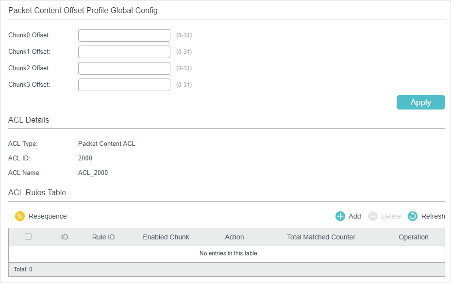
In the Packet Content Offset Profile Global Config section, configure the Chunk Offset. Click Apply.
|
Chunk0 Offset/Chunk1 Offset/Chunk2 Offset/Chunk3 Offset |
Enter the offset of a chunk. Packet Content ACL analyzes and processes data packets based on 4 chunk match conditions, and each chunk can specify a user-defined 4-byte segment carried in the packet’s first 128 bytes. Offset 31 matches the 127, 128, 1, 2 bytes of the packet, offset 0 matches the 3,4,5,6 bytes of the packet, and so on, for the rest of the offset value. Note: All 4 chunks must be set at the same time. |
In ACL Rules Table section, click and the following page will appear.
Figure 2-28 Configuring the Packet Content ACL Rule
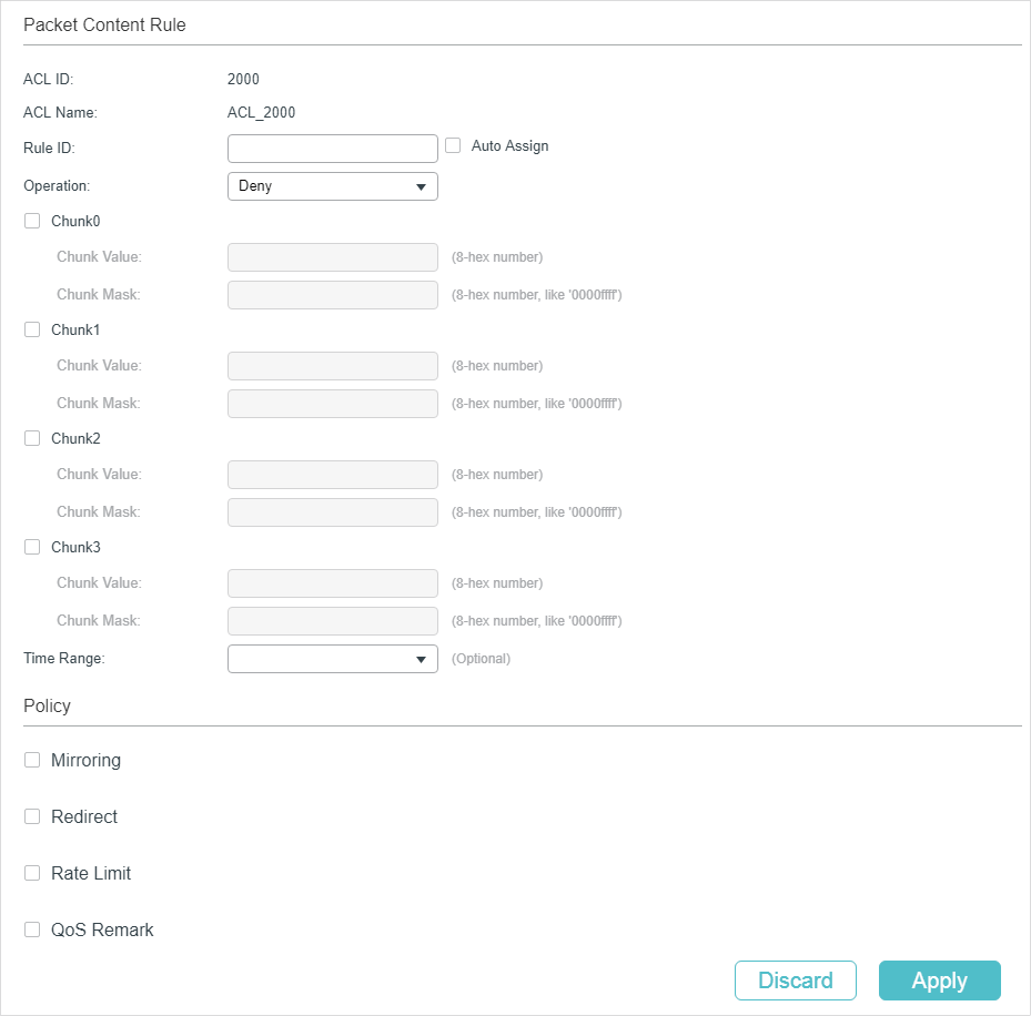
Follow these steps to configure the Packet Content ACL rule:
1)In the Packet Content Rule section, configure the following parameters:
|
Rule ID |
Enter an ID number to identify the rule. It should not be the same as any current rule ID in the same ACL. For the convenience of inserting new rules to an ACL, you should set the appropriate interval between rule IDs. If you select Auto Assign, the rule ID will be assigned automatically by the system and the default increment between neighboring rule IDs is 5 |
|
Operation |
Select an action to be taken when a packet matches the rule. Permit: To forward the matched packets. Deny: To discard the matched packets. |
|
Chunk0-Chunk3 |
Specify the EtherType to be matched using 4 hexadecimal numbers. |
|
Chunk Value |
Enter the 4-byte value in hexadecimal for the desired chunk, like ‘0000ffff’. The Packet Content ACL will check this chunk of packets to examine if the packets match the rule or not. |
|
Chunk Mask |
Enter the 4-byte mask in hexadecimal for the desired chunk. The mask must be written completely in 4-byte hex mode, like ‘0000ffff’. The mask specifies which bits to match the rule. |
|
Time Range |
Select a time range during which the rule will take effect. The default value is No Limit, which means the rule is always in effect. The Time Range referenced here can be created on the SYSTEM > Time Range page. |
|
Logging |
Enable Logging function for the ACL rule. Then the times that the rule is matched will be logged every 5 minutes and a related trap will be generated. You can refer to Total Matched Counter in the ACL Rules Table to view the matching times. |
2)In the Policy section, enable or disable the Mirroring feature for the matched packets. With this option enabled, choose a destination port to which the packets will be mirrored.
Figure 2-29 Configuring Mirroring
3)In the Policy section, enable or disable the Redirect feature for the matched packets. With this option enabled, choose a destination port to which the packets will be redirected.
Figure 2-30 Configuring Redirect
|
|
Note: In the Mirroring feature, the matched packets will be copied to the destination port and the original forwarding will not be affected. While in the Redirect feature, the matched packets will be forwarded only on the destination port. |
4)In the Policy section, enable or disable the Rate Limit feature for the matched packets. With this option enabled, configure the related parameters.
Figure 2-31 Configuring Rate Limit
|
Rate |
Specify the transmission rate for the matched packets. |
|
Burst Size |
Specify the maximum number of bytes allowed in one second. |
|
Out of Band |
Select the action for the packets whose rate is beyond the specified rate. None: The packets will be forwarded normally. Drop: The packets will be discarded. Remark DSCP: You can specify a DSCP value, and the DSCP field of the packets will be changed to the specified one. |
5)In the Policy section, enable or disable the QoS Remark feature for the matched packets. With this option enabled, configure the related parameters, and the remarked values will take effect in the QoS processing on the switch.
Figure 2-32 Configuring QoS Remark
|
DSCP |
Specify the DSCP field for the matched packets. The DSCP field of the packets will be changed to the specified one. |
|
Local Priority |
Specify the local priority for the matched packets. The local priority of the packets will be changed to the specified one. |
|
802.1p Priority |
Specify the 802.1p priority for the matched packets. The 802.1p priority of the packets will be changed to the specified one. |
6)Click Apply.
Viewing the ACL Rules
The rules in an ACL are listed in ascending order of their rule IDs. The switch matches a received packet with the rules in order. When a packet matches a rule, the switch stops the match process and performs the action defined in the rule.
Click Edit ACL for an entry you have created and you can view the rule table. We take IP ACL rules table for example.
Figure 2-33 Viewing ACL Rules Table
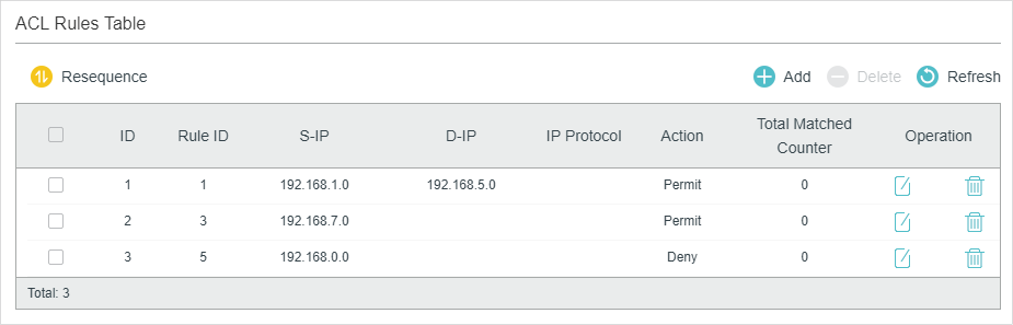
Here you can view and edit the ACL rules. You can also click Resequence to resequence the rules by providing a Start Rule ID and Step value.
2.1.4Configuring ACL Binding
You can bind the ACL to a port or a VLAN. The received packets on the port or in the VLAN will then be matched and processed according to the ACL rules. An ACL takes effect only after it is bound to a port or VLAN.
|
|
Note: Different types of ACLs cannot be bound to the same port or VLAN. Multiple ACLs of the same type can be bound to the same port or VLAN. The switch matches the received packets using the ACLs in order. The ACL that is bound earlier has a higher priority. |
Binding the ACL to a Port
Choose the menu SECURITY > ACL > ACL Binding > Port Binding and click to load the following page.
Figure 2-34 Binding the ACL to a Port
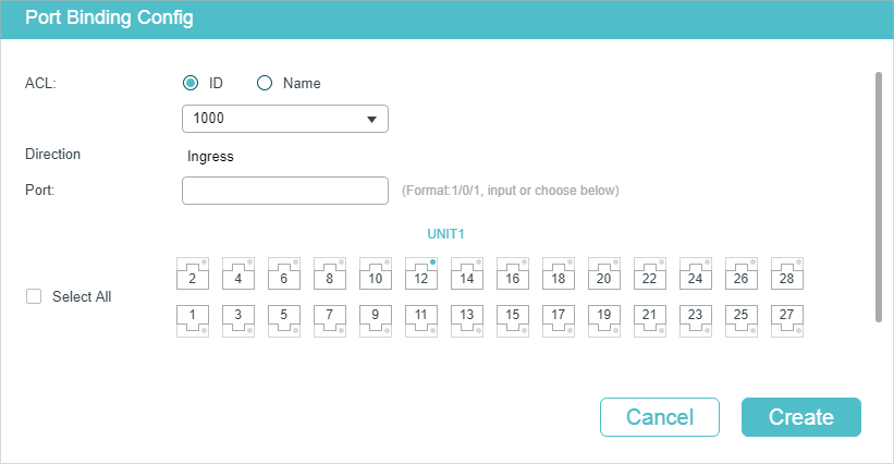
Follow these steps to bind the ACL to a Port:
1)Choose ID or Name to be used for matching the ACL. Then select an ACL from the drop-down list.
2)Specify the port to be bound.
3)Click Create.
Binding the ACL to a VLAN
Choose the menu SECURITY > ACL > ACL Binding > VLAN Binding to load the following page.
Figure 2-35 Binding the ACL to a VLAN
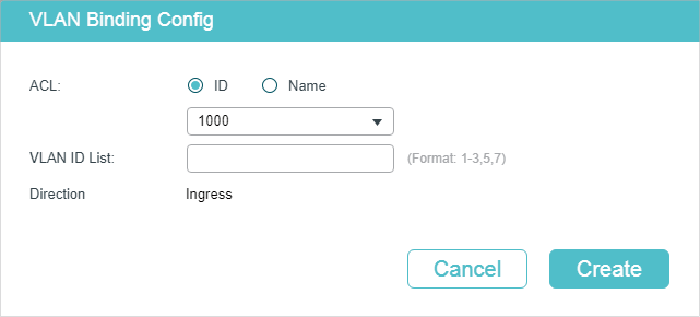
Follow these steps to bind the ACL to a VLAN:
1)Choose ID or Name to be used for matching the ACL. Then select an ACL from the drop-down list.
2)Enter the ID of the VLAN to be bound.
3)Click Create.
2.2Using the CLI
2.2.1Configuring Time Range
Some ACL-based services or features may need to be limited to take effect only during a specified time period. In this case, you can configure a time range for the ACL. For details about Time Range Configuration, please refer to Managing System.
2.2.2Configuring ACL
Follow the steps to create different types of ACL and configure the ACL rules.
You can define the rules based on source or destination IP address, source or destination MAC address, protocol type, port number and others.
MAC ACL
Follow these steps to configure MAC ACL:
|
Step 1 |
configure Enter global configuration mode. |
|
Step 2 |
access-list create acl-id [name acl-name] Create a MAC ACL. acl-id:Enter an ACL ID. The ID ranges from 0 to 499. acl-name: Enter a name to identify the ACL. |
|
Step 3 |
access-list mac acl-id-or-name rule { auto | rule-id } { deny | permit } logging {enable | disable} [ smac source-mac smask source-mac-mask ] [dmac destination-mac dmask destination-mac-mask ] [type ether-type] [pri dot1p-priority] [vid vlan-id] [tseg time-range-name] Add a MAC ACL Rule. acl-id-or-name: Enter the ID or name of the ACL that you want to add a rule for. auto: The rule ID will be assigned automatically and the interval between rule IDs is 5. rule-id: Assign an ID to the rule. deny | permit: Specify the action to be taken with the packets that match the rule. By default, it is set to permit. The packets will be discarded if “deny” is selected and forwarded if “permit” is selected. logging {enable | disable}: Enable or disable Logging function for the ACL rule. If «enable» is selected, the times that the rule is matched will be logged every 5 minutes. With ACL Counter trap enabled, a related trap will be generated if the matching times changes. source-mac: Enter the source MAC address. The format is FF:FF:FF:FF:FF:FF. source-mac-mask: Enter the mask of the source MAC address. This is required if a source MAC address is entered. The format is FF:FF:FF:FF:FF:FF. destination-mac: Enter the destination MAC address. The format is FF:FF:FF:FF:FF:FF. destination-mac-mask: Enter the mask of the destination MAC address. This is required if a destination MAC address is entered. The format is FF:FF:FF:FF:FF:FF. ether-type: Specify an Ethernet-type with 4 hexadecimal numbers. dot1p-priority: The user priority ranges from 0 to 7. The default is No Limit. vlan-id: The VLAN ID ranges from 1 to 4094. time-range-name: The name of the time-range. The default is No Limit. |
|
Step 4 |
exit Return to global configuration mode. |
|
Step 5 |
show access-list [ acl-id-or-name ] Display the current ACL configuration. acl-id-or-name: The ID number or name of the ACL. |
|
Step 6 |
end Return to privileged EXEC mode. |
|
Step 7 |
copy running-config startup-config Save the settings in the configuration file. |
The following example shows how to create MAC ACL 50 and configure Rule 5 to permit packets with source MAC address 00:34:A2:D4:34:B5:
Switch#configure
Switch(config)#access-list create 50
Switch(config-mac-acl)#access-list mac 50 rule 5 permit logging disable smac 00:34:A2:D4:34:B5 smask FF:FF:FF:FF:FF:FF
Switch(config-mac-acl)#exit
Switch(config)#show access-list 50
MAC access list 50 name: ACL_50
rule 5 permit logging disable smac 00:34:a2:d4:34:b5 smask ff:ff:ff:ff:ff:ff
Switch(config)#end
Switch#copy running-config startup-config
IP ACL
Follow these steps to configure IP ACL:
|
Step 1 |
configure Enter global configuration mode. |
|
Step 2 |
access-list create acl-id [name acl-name] Create an IP ACL. acl-id:Enter an ACL ID. The ID ranges from 500 to 999. acl-name: Enter a name to identify the ACL. |
|
Step 3 |
access-list ip acl-id-or-name rule {auto | rule-id } {deny | permit} logging {enable | disable} [sip sip-address sip-mask sip-address-mask ] [ dip dip-address dip-mask dip-address-mask ] [dscp dscp-value] [tos tos-value] [pre pre-value] [frag {enable | disable}] [protocol protocol [s-port s-port-number s-port-mask s-port-mask] [d-port d-port-number d-port-mask d-port-mask] [tcpflag tcpflag]] [tseg time-range-name] Add rules to the ACL. acl-id-or-name: Enter the ID or name of the ACL that you want to add a rule for. auto: The rule ID will be assigned automatically and the interval between rule IDs is 5. rule-id: Assign an ID to the rule. deny | permit: Specify the action to be taken with the packets that match the rule. Deny means to discard; permit means to forward. By default, it is set to permit. logging {enable | disable}: Enable or disable Logging function for the ACL rule. If «enable» is selected, the times that the rule is matched will be logged every 5 minutes. With ACL Counter trap enabled, a related trap will be generated if the matching times changes. sip-address: Enter the source IP address. sip-address-mask: Enter the mask of the source IP address. This is required if a source IP address is entered. dip-address: Enter the destination IP address. dip-address-mask: Enter the mask of the destination IP address. This is required if a destination IP address is entered. |
|
dscp-value: Specify the DSCP value between 0 and 63. tos-value: Specify an IP ToS value to be matched between 0 and 15. pre-value: Specify an IP Precedence value to be matched between 0 and 7. frag {enable | disable}: Enable or disable matching of fragmented packets. The default is disable. When enabled, the rule will apply to all fragmented packets and always permit to forward the last fragment of a packet. T1500 series, T1600G-18TS, T1600G-28TS, T1600G-28PS, T1600G-52TS v4 and T1600G-52PS v4 do not support this option. protocol: Specify a protocol number between 0 and 255. s-port-number: With TCP or UDP configured as the protocol, specify the source port number. s-port-mask: With TCP or UDP configured as the protocol, specify the source port mask with 4 hexadacimal numbers. d-port-number: With TCP or UDP configured as the protocol, specify the destination port number. d-port-mask: With TCP or UDP configured as the protocol, specify the destination port mask with 4 hexadacimal numbers. tcpflag: With TCP configured as the protocol, specify the flag value using either binary numbers or * (for example, 01*010*). The default is *, which indicates that the flag will not be matched. The flags are URG (Urgent flag), ACK (Acknowledge Flag), PSH (Push Flag), RST (Reset Flag), SYN (Synchronize Flag) and FIN (Finish Flag). time-range-name: The name of the time-range. The default is No Limit. |
|
|
Step 4 |
end Return to privileged EXEC mode. |
|
Step 5 |
copy running-config startup-config Save the settings in the configuration file. |
The following example shows how to create IP ACL 600, and configure Rule 1 to permit packets with source IP address 192.168.1.100:
Switch#configure
Switch(config)#access-list create 600
Switch(config)#access-list ip 600 rule 1 permit logging disable sip 192.168.1.100 sip-mask 255.255.255.255
Switch(config)#show access-list 600
IP access list 600 name: ACL_600
rule 1 permit logging disable sip 192.168.1.100 smask 255.255.255.255
Switch(config)#end
Switch#copy running-config startup-config
Combined ACL
Follow these steps to configure Combined ACL:
|
Step 1 |
configure Enter global configuration mode |
|
Step 2 |
access-list create acl-id [name acl-name] Create a Combined ACL. acl-id:Enter an ACL ID. The ID ranges from 1000 to 1499. acl-name: Enter a name to identify the ACL. |
|
Step 3 |
access-list combined acl-id-or-name rule {auto | rule-id } {deny | permit} logging {enable | disable} [smac source-mac-address smask source-mac-mask] [dmac dest-mac-address dmask dest-mac-mask] [vid vlan-id] [type ether-type] [pri priority] [sip sip-address sip-mask sip-address-mask] [dip dip-address dip-mask dip-address-mask] [dscp dscp-value] [tos tos-value] [pre pre-value] [protocol protocol [s-port s-port-number s-port-mask s-port-mask] [d-port d-port-number d-port-mask d-port-mask] [tcpflag tcpflag]] [tseg time-range-name] Add rules to the ACL. acl-id-or-name: Enter the ID or name of the ACL that you want to add a rule for. auto: The rule ID will be assigned automatically and the interval between rule IDs is 5. rule-id: Assign an ID to the rule. deny | permit: Specify the action to be taken with the packets that match the rule. Deny means to discard; permit means to forward. By default, it is set to permit. logging {enable | disable}: Enable or disable Logging function for the ACL rule. If «enable» is selected, the times that the rule is matched will be logged every 5 minutes. With ACL Counter trap enabled, a related trap will be generated if the matching times changes. source-mac-address: Enter the source MAC address. source-mac-mask: Enter the source MAC address mask. dest-mac-address: Enter the destination MAC address. dest-mac-mask: Enter the destination MAC address mask. This is required if a destination MAC address is entered. vlan-id: The VLAN ID ranges from 1 to 4094. ether-type: Specify the Ethernet-type with 4 hexadecimal numbers. priority: The user priority ranges from 0 to 7. The default is No Limit. sip-address: Enter the source IP address. sip-address-mask: Enter the mask of the source IP address. It is required if source IP address is entered. dip-address: This is required if a source IP address is entered. dip-address-mask: Enter the destination IP address mask. This is required if a destination IP address is entered. dscp-value: Specify the DSCP value between 0 and 63. tos-value: Specify an IP ToS value to be matched between 0 and 15. pre-value: Specify an IP Precedence value to be matched between 0 and 7. |
|
protocol: Specify a protocol number between 0 and 255. s-port-number: With TCP or UDP configured as the protocol, specify the source port number. s-port-mask: With TCP or UDP configured as the protocol, specify the source port mask with 4 hexadacimal numbers. d-port-number: With TCP or UDP configured as the protocol, specify the destination port number. d-port-mask: With TCP or UDP configured as the protocol, specify the destination port mask with 4 hexadacimal numbers. tcpflag: With TCP configured as the protocol, specify the flag value using either binary numbers or * (for example, 01*010*). The default is *, which indicates that the flag will not be matched. The flags are URG (Urgent flag), ACK (Acknowledge Flag), PSH (Push Flag), RST (Reset Flag), SYN (Synchronize Flag), and FIN (Finish Flag). time-range-name: The name of the time-range. The default is No Limit. |
|
|
Step 4 |
end Return to privileged EXEC mode. |
|
Step 5 |
copy running-config startup-config Save the settings in the configuration file. |
The following example shows how to create Combined ACL 1100 and configure Rule 1 to deny packets with source IP address 192.168.3.100 in VLAN 2:
Switch#configure
Switch(config)#access-list create 1100
Switch(config)#access-list combined 1100 logging disable rule 1 permit vid 2 sip 192.168.3.100 sip-mask 255.255.255.255
Switch(config)#show access-list 2600
Combined access list 2600 name: ACL_2600
rule 1 permit logging disable vid 2 sip 192.168.3.100 sip-mask 255.255.255.255
Switch(config)#end
Switch#copy running-config startup-config
IPv6 ACL
Follow these steps to configure IPv6 ACL:
|
Step 1 |
configure Enter global configuration mode |
|
Step 2 |
access-list create acl-id [name acl-name] Create an IPv6 ACL. acl-id:Enter an ACL ID. The ID ranges from 1500 to 1999. acl-name: Enter a name to identify the ACL. |
|
Step 3 |
access-list ipv6 acl-id-or-name rule {auto | rule-id } {deny | permit} logging {enable | disable} [class class-value] [flow-label flow-label-value] [sip source-ip-address sip-mask source-ip-mask ] [dip destination-ip-address dip-mask destination-ip-mask] [s-port source-port-number] [d-port destination-port-number] [tseg time-range-name] Add rules to the ACL. acl-id-or-name: Enter the ID or name of the ACL that you want to add a rule for. auto: The rule ID will be assigned automatically and the interval between rule IDs is 5. rule-id: Assign an ID to the rule. deny | permit: Specify the action to be taken with the packets that match the rule. Deny means to discard; permit means to forward. By default, it is set to permit. logging {enable | disable}: Enable or disable Logging function for the ACL rule. If «enable» is selected, the times that the rule is matched will be logged every 5 minutes. With ACL Counter trap enabled, a related trap will be generated if the matching times changes. class-value: Specify a class value to be matched. It ranges from 0 to 63. flow-label-value: Specify a Flow Label value to be matched. source-ip-address: Enter the source IP address. Enter the destination IPv6 address to be matched. All types of IPv6 address will be checked. You may enter a complete 128-bit IPv6 address but only the first 64 bits will be valid. source-ip-mask: Enter the source IP address mask. The mask is required if the source IPv6 address is entered. Enter the mask in complete format (for example, ffff:ffff:0000:ffff). The mask specifies which bits in the source IPv6 address to match the rule. destination-ip-address: Enter the destination IPv6 address to be matched. All types of IPv6 address will be checked. You may enter a complete 128-bit IPv6 addresses but only the first 64 bits will be valid. destination-ip-mask: Enter the source IP address mask. The mask is required if the source IPv6 address is entered. Enter the mask in complete format (for example, ffff:ffff:0000:ffff). The mask specifies which bits in the source IPv6 address to match the rule. source-port-number: Enter the TCP/UDP source port if TCP/UDP protocol is selected. destination-port-number: Enter the TCP/UDP destination port if TCP/UDP protocol is selected. time-range-name: The name of the time-range. The default is No Limit. |
|
Step 4 |
end Return to privileged EXEC mode. |
|
Step 5 |
copy running-config startup-config Save the settings in the configuration file. |
The following example shows how to create IPv6 ACL 1600 and configure Rule 1 to deny packets with source IPv6 address CDCD:910A:2222:5498:8475:1111:3900:2020:
Switch#configure
Switch(config)#access-list create 1600
Switch(config)#access-list ipv6 1600 rule 1 deny logging disable sip CDCD:910A:2222:5498:8475:1111:3900:2020 sip-mask ffff:ffff:ffff:ffff
Switch(config)#show access-list 1600
IPv6 access list 1600 name: ACL_1600
rule 1 deny logging disable sip cdcd:910a:2222:5498:8475:1111:3900:2020 sip-mask ffff:ff
ff:ffff:ffff
Switch(config)#end
Switch#copy running-config startup-config
Packet Content ACL
Only T2600G series support this feature.
Follow these steps to configure Packet Content ACL:
|
Step 1 |
configure Enter global configuration mode |
|
Step 2 |
access-list create acl-id [name acl-name] Create a Packet Content ACL. acl-id:Enter an ACL ID. The ID ranges from 2000 to 2499. acl-name: Enter a name to identify the ACL. |
|
Step 3 |
access-list packet-content profile chunk-offset0 offset0 chunk-offset1 offset1 chunk-offset2 offset2 chunk-offset3 offset3 Specify the offset of each chunk, all the 4 chunks must be set at the same time. offset0 —offset3: Specify the offset of each chunk, the value ranges from 0 to 31. When the offset is set as 31, it matches the first 127,128, 1, 2 bytes of the packet; when the offset is set as 0, it matches the 3, 4, 5, 6 bytes, and so on, for the rest of the offset value. |
|
Step 4 |
access-list packet-content config acl-id-or-name rule { auto | rule-id } {deny | permit} logging { enable | disable } [chunk0 value mask0 mask] [chunk1 value mask1 mask] [chunk2 value mask2 mask] [chunk3 value mask3 mask] [tseg time-range-name] Add rules to the ACL. acl-id-or-name: Enter the ID or name of the ACL that you want to add a rule for. auto: The rule ID will be assigned automatically and the interval between rule IDs is 5. rule-id: Assign an ID to the rule. deny | permit: Specify the action to be taken with the packets that match the rule. Deny means to discard; permit means to forward. By default, it is set to permit. logging { enable | disable} : Enable or disable Logging function for the ACL rule. If «enable» is selected, the times that the rule is matched will be logged every 5 minutes. With ACL Counter trap enabled, a related trap will be generated if the matching times changes. value: Enter the 4-byte value in hexadecimal for the desired chunk, like ‘0000ffff’. The Packet Content ACL will check this chunk of packets to examine if the packets match the rule or not. mask: Enter the 4-byte mask in hexadecimal for the desired chunk. The mask must be written completely in 4-byte hex mode, like ‘0000ffff’. The mask specifies which bits to match the rule. time-range-name: The name of the time-range. The default is No Limit. |
|
Step 5 |
end Return to privileged EXEC mode. |
|
Step 6 |
copy running-config startup-config Save the settings in the configuration file. |
The following example shows how to create Packet Content ACL 2000, and deny the packets with the value of its chunk1 0x58:
Switch#configure
Switch(config)#access-list create 2000
Switch(config)#access-list packet-content profile chunk-offset0 offset0 chunk-offset1 offset1 chunk-offset2 offset2 chunk-offset3 offset3
Switch(config)#packet-content config 2000 rule 10 deny logging disable chunk1 58 mask1 ffffffff
Switch(config)#show access-list 2000
Packet content access list 2000 name: ACL_2000
rule 10 deny logging disable chunk1 value 0x58 mask 0xffffffff
Switch(config)#end
Switch#copy running-config startup-config
Resequencing Rules
You can resequence the rules by providing a Start Z and Step value.
|
Step 1 |
configure Enter global configuration mode. |
|
Step 2 |
access-list resequence acl-id-or-name start start-rule-id step rule-id-step-value Resequence the rules of the specific ACL. acl-id-or-name: Enter the ID or name of the ACL. start-rule-id: Enter the start rule ID. rule-id-step-value: Enter the Step value. |
|
Step 3 |
end Return to privileged EXEC mode. |
|
Step 4 |
copy running-config startup-config Save the settings in the configuration file. |
The following example shows how to resequence the rules of MAC ACL 100: set the start rule ID as 1 and the step value as 10:
Switch#configure
Switch(config)#access-list resequence 100 start 1 step 10
Switch(config)#show access-list 100
MAC access list 100 name: “ACL_100”
rule 1 deny logging disable smac aa:bb:cc:dd:ee:ff smask ff:ff:ff:ff:ff:ff
rule 11 permit logging disable vid 18
rule 21 permit logging disable dmac aa:cc:ee:ff:dd:33 dmask ff:ff:ff:ff:ff:ff
Switch(config)#end
Switch#copy running-config startup-config
2.2.3Configuring Policy
Policy allows you to further process the matched packets through operations such as mirroring, rate-limiting, redirecting, or changing priority.
Follow the steps below to configure the policy actions for an ACL rule.
|
Step 1 |
configure Enter global configuration mode. |
|
Step 2 |
access-list action acl-id-or-name rule rule-id Configure the policy actions for an ACL rule. acl-id-or-name: Enter the ID or name of the ACL. rule-id: Enter the ID of the ACL rule. |
|
Step 3 |
redirect interface { fastEthernet port | gigabitEthernet port | ten-gigabitEthernet port } (Optional) Define the policy to redirect the matched packets to the desired port. port: The destination port to which the packets will be redirected. The default is All. s-mirror interface { fastEthernet port | gigabitEthernet port | ten-gigabitEthernet port } (Optional) Define the policy to mirror the matched packets to the desired port. port: The destination port to which the packets will be mirrored. s-condition rate rate burst burst-size osd { none | discard | remark dscp dscp } (Optional) Define the policy to monitor the rate of the matched packets. rate: Specify a rate from 1 to 1000000 kbps. burst-size: Specify the number of bytes allowed in one second ranging from 1 to 128. osd: Select either “none”, “discard” or “remark dscp” as the action to be taken for the packets whose rate is beyond the specified rate. The default is None. When “remark dscp” is selected, you also need to specify the DSCP value for the matched packets. The DSCP value ranges from 0 to 63. T1500 series, T1600G-18TS, T1600G-28TS, T1600G-28PS, T1600G-52TS v4 and T1600G-52PS v4 do not support DSCP option. qos-remark [dscp dscp] [ priority pri ] [ dot1p pri ] (Optional) Define the policy to remark priority for the matched packets. dscp: Specify the DSCP region for the data packets. The value ranges from 0 to 63. priority pri: Specify the local priority for the data packets. The value ranges from 0 to 7. dot1p pri: Specify the 802.1p priority for the data packets. The value ranges from 0 to 7. |
|
Step 4 |
end Return to privileged EXEC mode. |
|
Step 5 |
copy running-config startup-config Save the settings in the configuration file. |
Redirect the matched packets to port 1/0/4 for rule 1 of MAC ACL 10:
Switch#configure
Switch(config)#access-list action 10 rule 1
Switch(config-action)#redirect interface gigabitEthernet 1/0/4
Switch(config-action)#exit
Switch(config)#show access-list 10
MAC access list 10 name: ACL_10
rule 5 permit logging disable action redirect Gi1/0/4
Switch(config)#end
Switch#copy running-config startup-config
2.2.4Configuring ACL Binding
You can bind the ACL to a port or a VLAN. The received packets on the port or in the VLAN will then be matched and processed according to the ACL rules. An ACL takes effect only after it is bound to a port or VLAN.
|
|
Note: Different types of ACLs cannot be bound to the same port or VLAN. Multiple ACLs of the same type can be bound to the same port or VLAN. The switch matches the received packets using the ACLs in order. The ACL that is bound earlier has a higher priority. |
Follow the steps below to bind ACL to a port or a VLAN:
|
Step 1 |
configure Enter global configuration mode |
|
Step 2 |
access-list bind acl-id-or-name interface { [ vlan vlan-list ] | [ fastEthernet port-list ] | [ gigabitEthernet port-list ] | [ ten-gigabitEthernet port-list ] } Bind the ACL to a port or a VLAN. acl-id-or-name: Enter the ID or name of the ACL that you want to add a rule for. vlan-list: Specify the ID or the ID list of the VLAN(s) that you want to bind the ACL to. The valid values are from 1 to 4094, for example, 2-3,5. port-list: Specify the number or the list of the Ethernet port that you want to bind the ACL to. |
|
Step 3 |
show access-list bind View the ACL binding configuration. |
|
Step 4 |
end Return to privileged EXEC mode. |
|
Step 5 |
copy running-config startup-config Save the settings in the configuration file. |
The following example shows how to bind ACL 1 to port 3 and VLAN 4:
Switch#configure
Switch(config)#access-list bind 1 interface vlan 4 gigabitEthernet 1/0/3
SSwitch(config)#show access-list bind
ACL ID ACL NAME Interface/VID Direction Type
—— ———- ————- ——- —-
1 ACL_1 Gi1/0/3 Ingress Port
1 ACL_1 4 Ingress VLAN
Switch(config)#end
Switch#copy running-config startup-config
2.2.5Viewing ACL Counting
You can use the following command to view the number of matched packets of each ACL in the privileged EXEC mode and any other configuration mode:
|
show access-list acl-id-or-name counter View the number of matched packets of the specific ACL. acl-id-or-name: Specify the ID or name of the ACL to be viewed. |
3Configuration Example for ACL
3.1Configuration Example for MAC ACL
3.1.1Network Requirements
A company forbids the employees in the R&D department to visit the internal forum during work hours. While the manager of the R&D department can get access to the internal forum without limitation.
As shown below, the internal forum server is connected to the switch via port 1/0/1, and computers in the R&D department are connected to the switch via port 1/0/2.
Figure 3-1 Network Topology
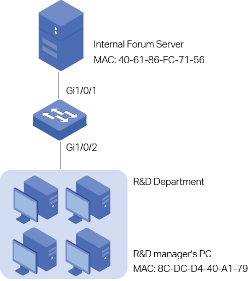
3.1.2Configuration Scheme
To meet the requirements above, you can set up packet filtering by creating an MAC ACL and configuring rules for it.
Time Range Configuration
Create a time range entry for the work hour of the company. Apply the time range to the ACL rule which blocks the access to internal forum server.
ACL Configuration
Create a MAC ACL and configure the following rules for it:
Configure a permit rule to match packets with source MAC address 8C-DC-D4-40-A1-79 and destination MAC address 40-61-86-FC-71-56. This rule allows the manager of R&D department to visit internal forum at any time.
Configure a deny rule to match packets with destination MAC address 40-61-86-FC-71-56 and apply the time range of work hours. This rule forbids the employees in the R&D department to visit the internal forum during work hours.
Configure a permit rule to match all the packets that do not match neither of the above rules.
Binding Configuration
Bind the MAC ACL to port 1/0/2 so that the ACL rules will be applied to the computer of the devices in the R&D department which are restricted to the internal forum during work hours.
Demonstrated with T2600G-28TS, the following sections explain the configuration procedure in two ways: using the GUI and using the CLI.
3.1.3Using the GUI
1)Choose the menu SYSTEM > Time Range > Time Range Config and click to load the following page. Create a time range named Work_time.
Figure 3-2 Configuring Time Range
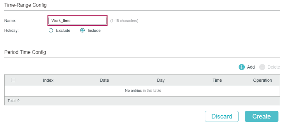
2)In the Period Time Config section, click and the following window will pop up. Add the work hour of the company in the Period Time and click Save.
Figure 3-3 Adding Period Time
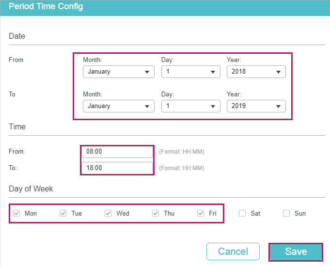
3)After adding the Period Time, click Create to save the time range entry.
Figure 3-4 Creating Time Range
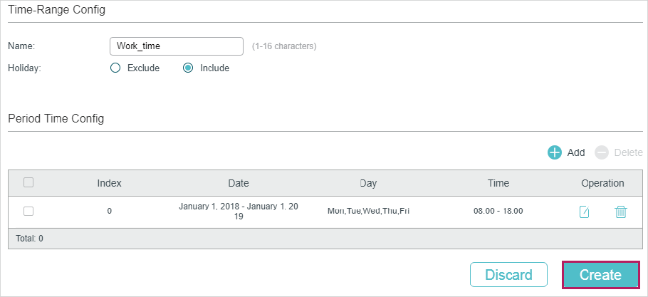
4)Choose the menu SECURITY > ACL > ACL Config and click to load the following page. Then create a MAC ACL for the marketing department.
Figure 3-5 Creating a MAC ACL
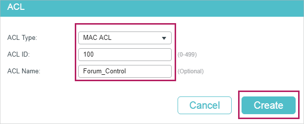
5)Click Edit ACL in the Operation column.
Figure 3-6 Editing the MAC ACL
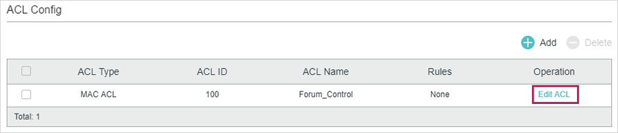
6)On the ACL configuration page, click .
Figure 3-7 Editing the MAC ACL
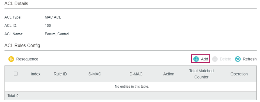
7)Configure rule 5 to permit packets with the source MAC address 8C-DC-D4-40-A1-79 and destination MAC address 40-61-86-FC-71-56.
Figure 3-8 Configuring Rule 5
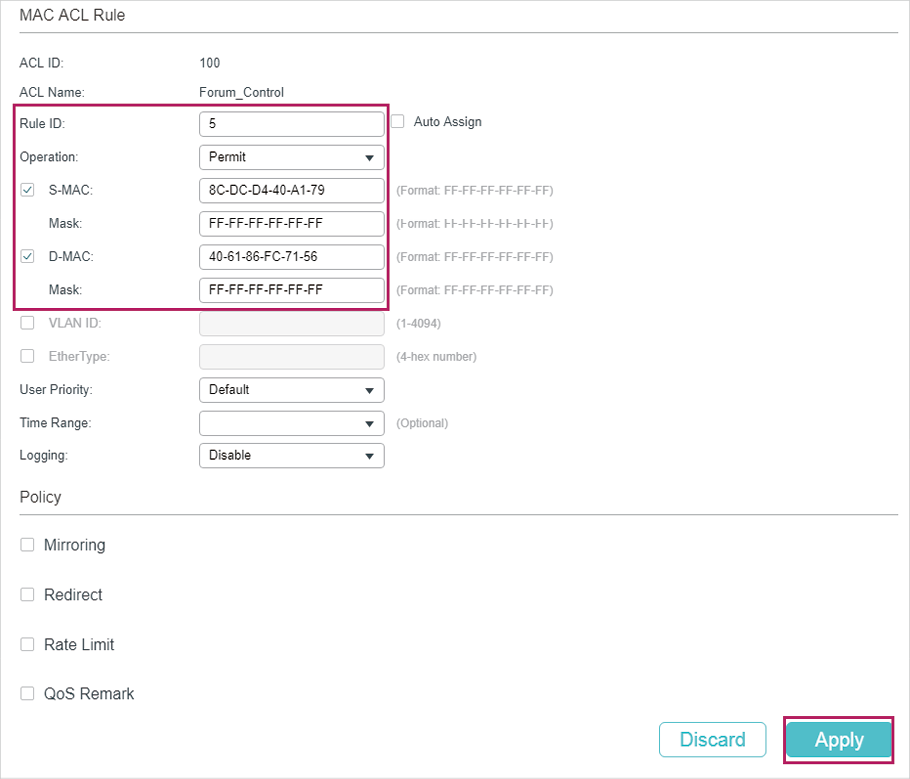
 In the same way, configure rule 15 to deny packets with destination MAC address 40-61-86-FC-71-56 and apply the time range of work hours.
Figure 3-9 Configuring Rule 15
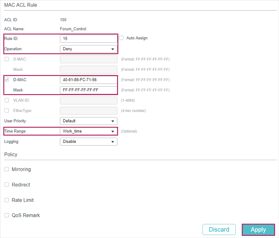
9)Configure rule 25 to permit all the packets that do not match neither of the above rules.
Figure 3-10 Configuring Rule 25
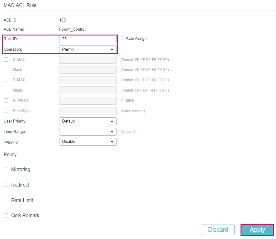
10)Choose the menu SECURITY > ACL > ACL Binding and click to load the following page. Bind ACL 100 to port 1/0/2 to make it take effect.
Figure 3-11 Binding the ACL to Port 1/0/2
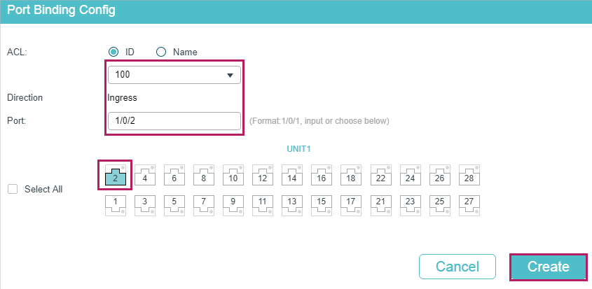
11)Click to save the settings.
3.1.4Using the CLI
1)Create a time range entry .
Switch#config
Switch(config)#time-range Work_time
Switch(config-time-range)#holiday include
Switch(config-time-range)#absolute from 01/01/2018 to 01/01/2019
Switch(config-time-range)#periodic start 08:00 end 18:00 day-of-the-week 1,2,3,4,5
Switch(config-time-range)#end
Switch#copy running-config startup-config
2)Create a MAC ACL.
Switch#configure
Switch(config)#access-list create 100 name Forum_Control
3)Configure rule 5 to permit packets with source MAC address 8C-DC-D4-40-A1-79 and destination MAC address 40-61-86-FC-71-56.
Switch(config)#access-list mac 100 rule 5 permit logging disable smac 8C:DC:D4:40:A1:79 smask FF: FF: FF: FF: FF: FF dmac 40:61:86:FC:71:56 dmask FF: FF: FF: FF: FF: FF
4)Configure rule 15 to deny packets with destination MAC address 40-61-86-FC-71-56.
Switch(config)#access-list mac 100 rule 15 deny logging disable dmac 40:61:86:FC:71:56 dmask FF: FF: FF: FF: FF: FF tseg Work_time
5)Configure rule 25 to permit all the packets. The rule makes sure that the traffic to other network resources will not be blocked by the switch.
Switch(config)#access-list mac 100 rule 25 permit logging disable
6)Bind ACL100 to port 1/0/2.
Switch(config)#access-list bind 100 interface gigabitEthernet 1/0/2
Switch(config)#end
Switch#copy running-config startup-config
Verify the Configurations
Verify the MAC ACL 100:
Switch#show access-list 100
MAC access list 100 name: “Forum_Control”
rule 5 permit logging disable smac 8c:dc:d4:40:a1:79 smask ff:ff:ff:ff:ff:ff dmac 40:61:86:fc:71:56 dmask ff:ff:ff:ff:ff:ff
rule 15 deny logging disable dmac 40:61:86:fc:71:56 dmask ff:ff:ff:ff:ff:ff tseg “Work_time”
rule 25 permit logging disable
Switch#show access-list bind
ACL ID ACL NAME Interface/VID Direction Type
—— ——— ————- ——— —-
100 Forum_Control Gi1/0/2 Ingress Port
3.2Configuration Example for IP ACL
3.2.1Network Requirements
As shown below, a company’s internal server group can provide different types of services. Computers in the Marketing department are connected to the switch via port 1/0/1, and the internal server group is connected to the switch via port 1/0/2.
Figure 3-12 Network Topology
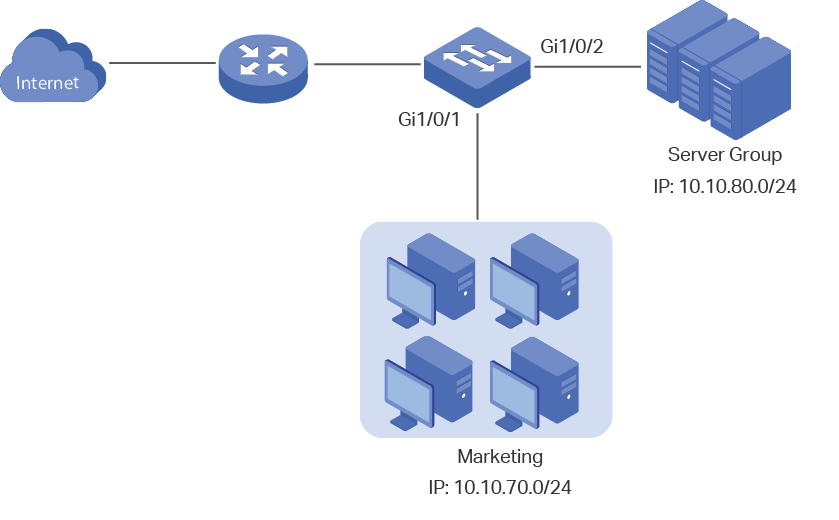
It is required that:
The Marketing department can only access internal server group in the intranet.
The Marketing department can only visit http and https websites on the internet.
3.2.2Configuration Scheme
To meet the requirements above, you can set up packet filtering by creating an IP ACL and configuring rules for it.
ACL Configuration
Create an IP ACL and configure the following rules for it:
Configure a permit rule to match packets with source IP address 10.10.70.0/24, and destination IP address 10.10.80.0/24. This rule allows the Marketing department to access internal network servers from intranet.
Configure four permit rules to match the packets with source IP address 10.10.70.0/24, and destination ports TCP 80, TCP 443 and TCP/UDP 53. These allow the Marketing department to visit http and https websites on the internet.
Configure a deny rule to match the packets with source IP address 10.10.70.0/24. This rule blocks other network services.
The switch matches the packets with the rules in order, starting with Rule 1. If a packet matches a rule, the switch stops the matching process and initiates the action defined in the rule.
Binding Configuration
Bind the IP ACL to port 1/0/1 so that the ACL rules will apply to the Marketing department only.
Demonstrated with T2600G-28TS, the following sections explain the configuration procedure in two ways: using the GUI and using the CLI.
3.2.3Using the GUI
1)Choose the menu SECURITY > ACL > ACL Config and click to load the following page. Then create an IP ACL for the marketing department.
Figure 3-13 Creating an IP ACL
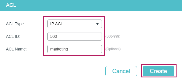
2)Click Edit ACL in the Operation column.
Figure 3-14 Editing IP ACL
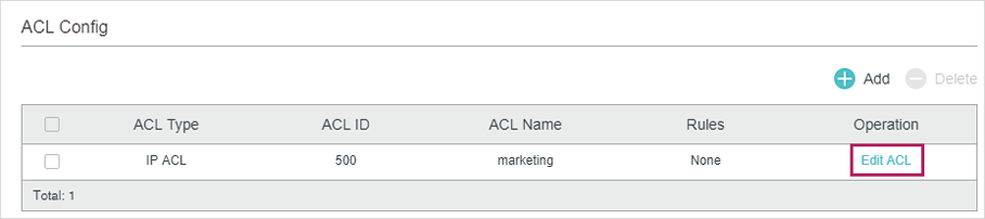
3)On the ACL configuration page, click .
Figure 3-15 Editing IP AC
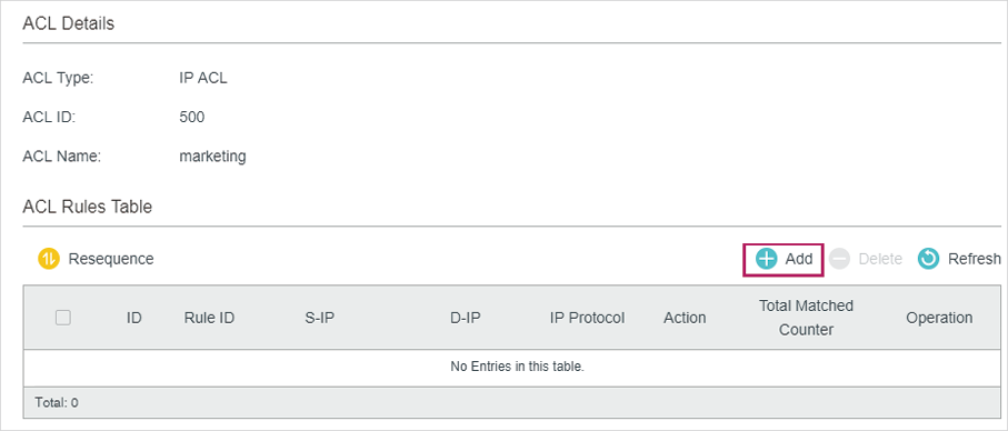
4)Configure rule 1 to permit packets with the source IP address 10.10.70.0/24 and destination IP address 10.10.80.0/24.
Figure 3-16 Configuring Rule 1
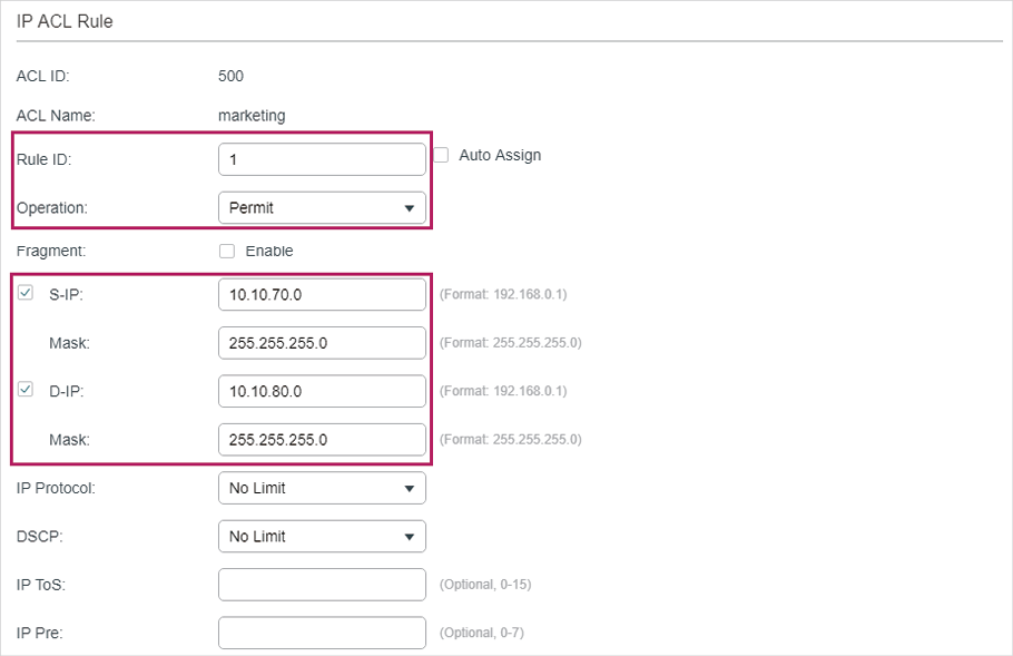
5)In the same way, configure rule 2 and rule 3 to permit packets with source IP 10.10.70.0 and destination port TCP 80 (http service port) and TCP 443 (https service port).
Figure 3-17 Configuring Rule 2
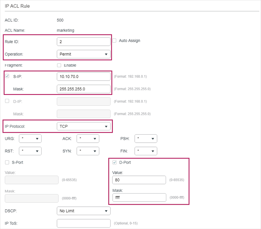
Figure 3-18 Configuring Rule 3
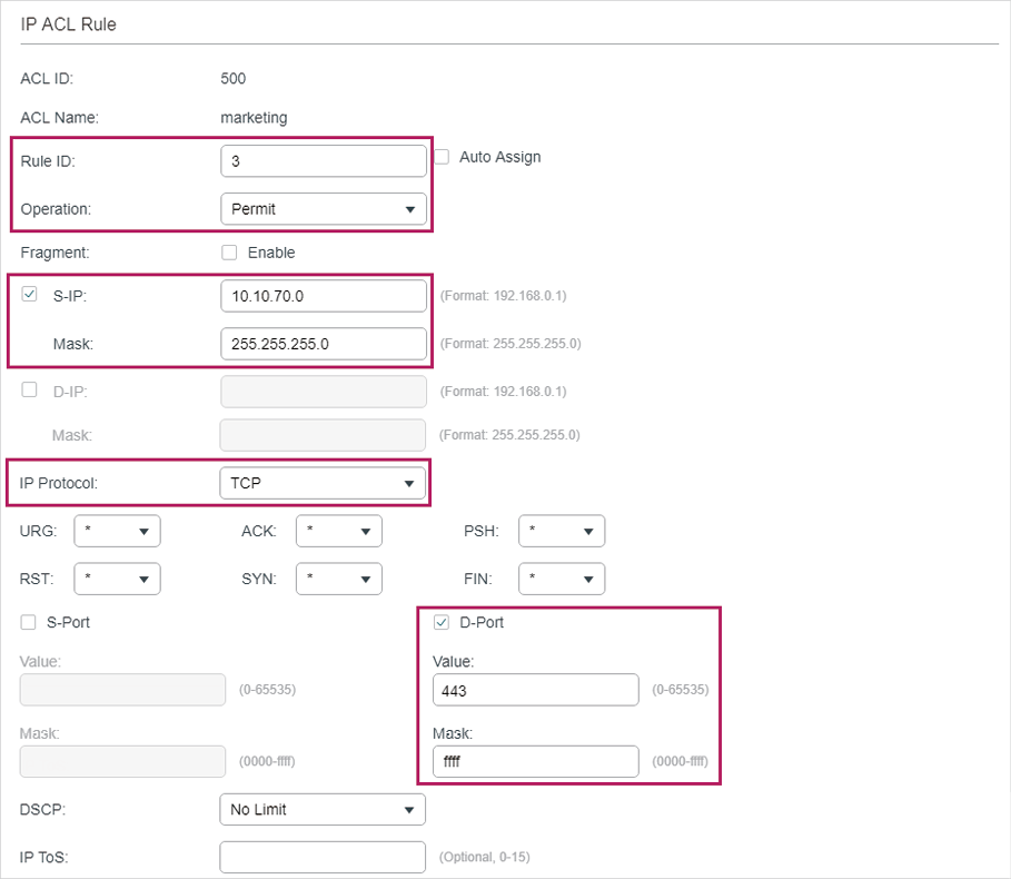
6)In the same way, configure rule 4 and rule 5 to permit packets with source IP 10.10.70.0 and with destination port TCP 53 or UDP 53 (DNS service port).
Figure 3-19 Configuring Rule 4
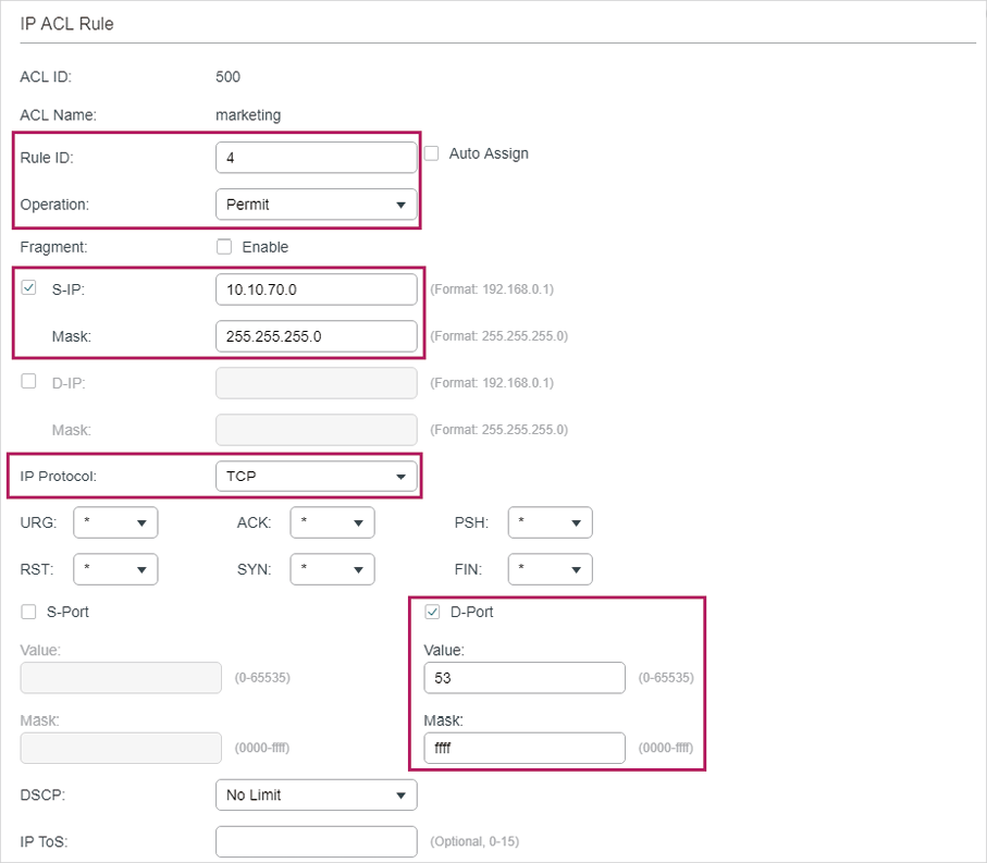
Figure 3-20 Configuring Rule 5
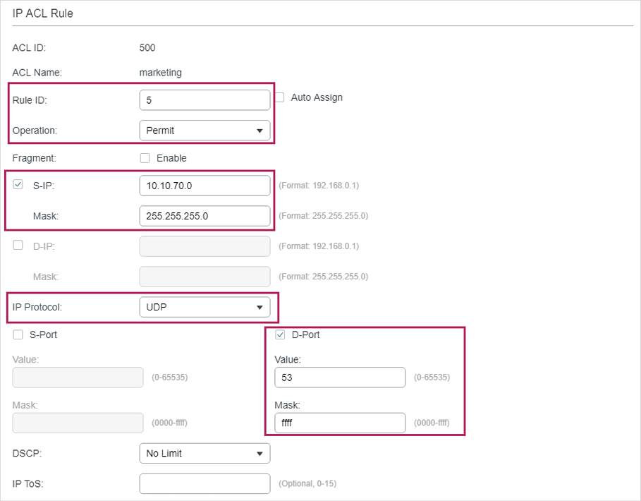
7)In the same way, configure rule 6 to deny packets with source IP 10.10.70.0.
Figure 3-21 Configuring Rule 6
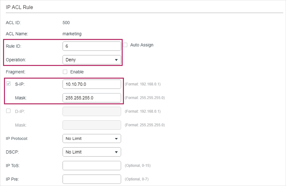
Choose the menu SECURITY > ACL > ACL Binding and click to load the following page. Bind ACL Marketing to port 1/0/1 to make it take effect.
Figure 3-22 Binding the ACL to Port 1/0/1
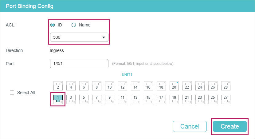
9)Click to save the settings.
3.2.4Using the CLI
1)Create an IP ACL.
Switch#configure
Switch(config)#access-list create 500 name marketing
2)Configure rule 1 to permit packets with source IP 10.10.70.0/24 and destination IP 10.10.80.0/24.
Switch(config)#access-list ip 500 rule 1 permit logging disable sip 10.10.70.0 sip-mask 255.255.255.0 dip 10.10.80.0 dmask 255.255.255.0
3)Configure rule 2 and Rule 3 to permit packets with source IP 10.10.70.0/24, and destination port TCP 80 (http service port) or TCP 443 (https service port).
Switch(config)#access-list ip 500 rule 2 permit logging disable sip 10.10.70.0 sip-mask 255.255.255.0 protocol 6 d-port 80 d-port-mask ffff
Switch(config)#access-list ip 500 rule 3 permit logging disable sip 10.10.70.0 sip-mask 255.255.255.0 protocol 6 d-port 443 d-port-mask ffff
4)Configure rule 4 and rule 5 to permit packets with source IP 10.10.70.0/24, and destination port TCP53 or UDP 53.
Switch(config)#access-list ip 500 rule 4 permit logging disable sip 10.10.70.0 sip-mask 255.255.255.0 protocol 6 d-port 53 d-port-mask ffff
Switch(config)#access-list ip 500 rule 5 permit logging disable sip 10.10.70.0 sip-amask 255.255.255.0 protocol 17 d-port 53 d-port-mask ffff
5)Configure rule 6 to deny packets with source IP 10.10.70.0/24.
Switch(config)#access-list ip 500 rule 2 deny logging disable sip 10.10.70.0 sip-mask 255.255.255.0
6)Bind ACL500 to port 1.
Switch(config)#access-list bind 500 interface gigabitEthernet 1/0/1
Switch(config)#end
Switch#copy running-config startup-config
Verify the Configurations
Verify the IP ACL 500:
Switch#show access-list 500
rule 1 permit logging disable sip 10.10.70.0 smask 255.255.255.0 dip 10.10.80.0 dmask 255.255.255.0
rule 2 permit logging disable sip 10.10.70.0 smask 255.255.255.0 protocol 6 d-port 80
rule 3 permit logging disable sip 10.10.70.0 smask 255.255.255.0 protocol 6 d-port 443
rule 4 permit logging disable sip 10.10.70.0 smask 255.255.255.0 protocol 6 d-port 53
rule 5 permit logging disable sip 10.10.70.0 smask 255.255.255.0 protocol 17 d-port 53
rule 6 deny loggin disable sip 10.10.70.0 smask 255.255.255.0
Switch#show access-list bind
ACL ID ACL NAME Interface/VID Direction Type
—— ——— ————- ——— —-
500 marketing Gi1/0/1 Ingress Port
3.3Configuration Example for Combined ACL
3.3.1Network Requirements
To enhance network security, a company requires that only the network administrator can log in to the switch through Telnet connection. The computers are connected to the switch via port 1/0/2. The network topology is shown as below.
Figure 3-23 Network Topology
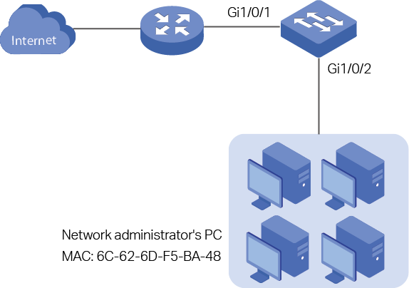
3.3.2Configuration Scheme
To meet the requirements above, you can set up packet filtering by creating a Combined ACL and configuring rules for it.
ACL Configuration
Create a Combined ACL and configure the following rules for it:
Configure a permit rule to match packets with source MAC address 6C-62-6D-F5-BA-48, and destination port TCP 23. This rule allows the computer of the network administrator to access the switch through Telnet connection.
Configure a deny rule to match all the packets except the packets with source MAC address 6C-62-6D-F5-BA-48 and destination port TCP 23. This rule blocks the Telnet connection to the switch of other computers.
Configure a permit rule to match all the packets. This rule allows that other devices are given the network services except Telnet connection.
The switch matches the packets with the rules in order, starting with Rule 1. If a packet matches a rule, the switch stops the matching process and initiates the action defined in the rule.
Binding Configuration
Bind the Combined ACL to port 1/0/2 so that the ACL rules will be applied to the computer of the network administrator and the devices which are restricted to Telnet connection.
Demonstrated with T2600G-28TS, the following sections explain the configuration procedure in two ways: using the GUI and using the CLI.
3.3.3Using the GUI
1)Choose the menu SECURITY > ACL > ACL Config and click to load the following page. Then create a Combined ACL for the marketing department.
Figure 3-24 Creating an Combined ACL
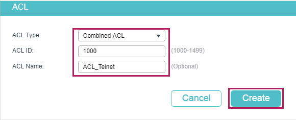
2)Click Edit ACL in the Operation column.
Figure 3-25 Editing Combined ACL
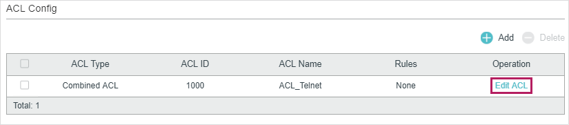
3)On the ACL configuration page, click .
Figure 3-26 Editing Combined ACL
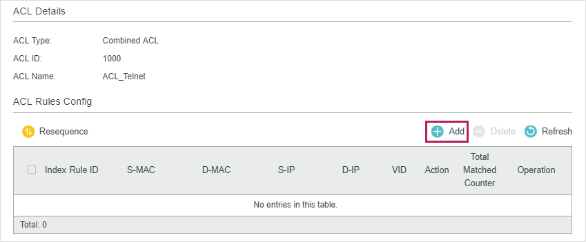
4)Configure rule 5 to permit packets with the source MAC address 6C-62-6D-F5-BA-48 and destination port TCP 23 (Telnet service port).
Figure 3-27 Configuring Rule 5
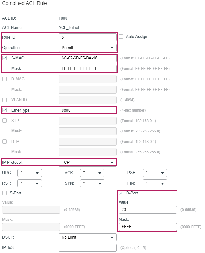
5)Configure rule 15 to deny all the packets except the packet with source MAC address 6C-62-6D-F5-BA-48, and destination port TCP 23 (Telnet service port).
Figure 3-28 Configuring Rule 15
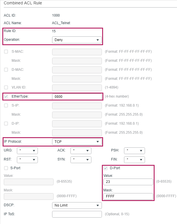
6)In the same way, configure rule 25 to permit all the packets. The rule makes sure that all devices can get other network services normally.
Figure 3-29 Configuring Rule 25
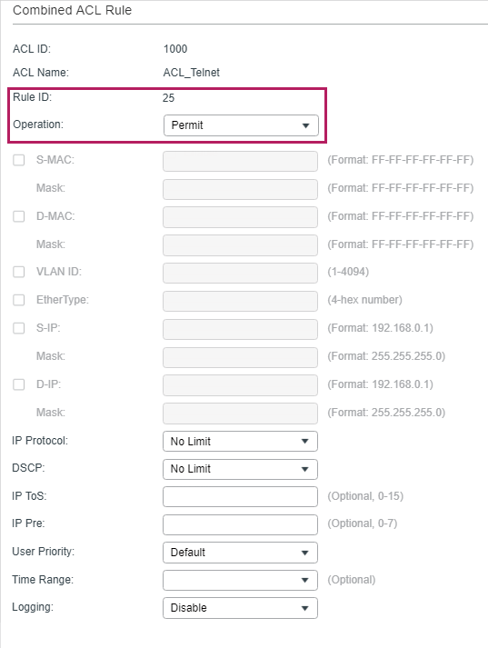
7)Choose the menu SECURITY > ACL > ACL Binding and click to load the following page. Bind the Policy ACL_Telnet to port 1/0/2 to make it take effect.
Figure 3-30 Binding the ACL to Port 1/0/2
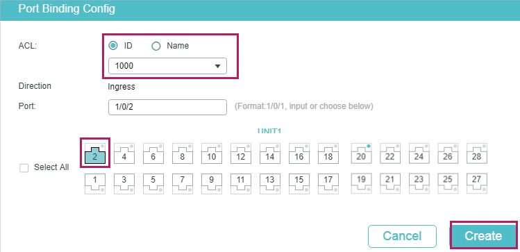
Click to save the settings.
3.3.4Using the CLI
1)Create a Combined ACL.
Switch#configure
Switch(config)#access-list create 1000 name ACL_Telnet
2)Configure rule 5 to permit packets with the source MAC address 6C-62-6D-F5-BA-48 and destination port TCP 23 (Telnet service port).
Switch(config)#access-list combined 1000 rule 5 permit logging disable smac 6C:62:6D:F5:BA: 48 smask FF: FF: FF: FF: FF: FF type 0800 protocol 6 d-port 23 d-port-mask FFFF
3)Configure rule 15 to deny all the packets except the packet with source MAC address 6C-62-6D-F5-BA-48, and destination port TCP 23 (Telnet service port).
Switch(config)#access-list combined 1000 rule 15 deny logging disable type 0800 protocol 6 d-port 23 d-port-mask FFFF
4)Configure rule 25 to permit all the packets. The rule makes sure that all devices can get other network services normally.
Switch(config)#access-list combined 1000 rule 25 permit logging disable type 0800 protocol 6 d-port 23 d-port-mask FFFF
5)Bind ACL500 to port 1/0/2.
Switch(config)#access-list bind 500 interface gigabitEthernet 1/0/2
Switch(config)#end
Switch#copy running-config startup-config
Verify the Configurations
Verify the Combined ACL 1000:
Switch#show access-list 1000
Combined access list 1000 name: “ACL_Telnet”
rule 5 permit logging disable smac 6c:62:6d:f5:ba:48 smask ff:ff:ff:ff:ff:ff type 0800 protocol 6 d-port 23
rule 15 deny logging disable type 0800 protocol 6 d-port 23
rule 25 permit logging disable
Switch#show access-list bind
ACL ID ACL NAME Interface/VID Direction Type
—— —————— ————- ——— —-
1000 ACL_Telnet Gi1/0/2 Ingress Port
4Appendix: Default Parameters
The default settings of ACL are listed in the following tables:
Table 4-1MAC ACL
|
Parameter |
Default Setting |
|
Operation |
Permit |
|
User Priority |
No Limit |
|
Time-Range |
No Limit |
Table 4-2IP ACL
|
Parameter |
Default Setting |
|
Operation |
Permit |
|
IP Protocol |
All |
|
DSCP |
No Limit |
|
IP ToS |
No Limit |
|
IP Pre |
No Limit |
|
Time-Range |
No Limit |
Table 4-3IPv6 ACL
|
Parameter |
Default Setting |
|
Operation |
Permit |
|
Time-Range |
No Limit |
Table 4-4Combined ACL
|
Parameter |
Default Setting |
|
Operation |
Permit |
|
Time-Range |
No Limit |
Table 4-5Packet Content ACL
|
Parameter |
Default Setting |
|
Operation |
Permit |
|
Time-Range |
No Limit |
Table 4-6Policy
|
Parameter |
Default Setting |
|
Mirroring |
Disabled |
|
Redirect |
Disabled |
|
Rate Limit |
Disabled |
|
QoS Remark |
Disabled |

3 ноября 2012, 17:10

18

1210461

165


Продолжаем развитие нашей маленькой уютной сети Лифт ми Ап. Мы уже обсудили вопросы маршрутизации и стабильности, и теперь, наконец, выросли для подключения к Интернету. Довольно заточения в рамках нашей корпоративной среды!
Но с развитием появляются и новые проблемы.
Сначала вирус парализовал веб-сервер, потом кто-то притаранил червя, который распространился в сети, заняв часть полосы пропускания. А ещё какой-то злодей повадился подбирать пароли на ssh к серверу.
А представляете, что начнётся, когда мы подключимся к Интернету?!
Итак, сегодня: учимся настраивать различные списки контроля доступа, пытаемся понять разницу между ограничением входящего и исходящего трафика, разбираемся с тем, как работает NAT, его плюсы, минусы и возможности, на практике организуем подключение к Интернету через NAT и увеличим безопасность сети, используя списки доступа.
Содержание выпуска
- ACL — Access Control List
- Виды ACL
- Маска и обратная маска
- Практика
- NAT — Network Address Translation
- Типы NAT
- Перенаправление портов
- Слабости и силости NAT
- Практика NAT
- Безопасность
- Бонусы
- PBR в режиме глобальной конфигурации
- rate-limit
- Материалы выпуска
Access Control List
Итак, что мы имеем сказать по спискам доступа? Вообще-то тема относительно простая и только ленивыми из курса CCNA не скопипащена. Но не разрывать же нам наше удивительное повествование из-за каких то предрассудков?
Каково предназначение списков доступа? Казалось бы, совершенно очевидный ответ — для ограничения доступа: кому-то что-то запретить, например. Вообще — это верно, но понимать нужно в более широком смысле: речь не только о безопасности. То есть, изначально, вероятно, так оно и было, отсюда permit и deny при настройке. Но на самом деле ACL — это универсальный и мощный механизм фильтрации. С их помощью можно определить на кого навешивать определённые политики, а на кого нет, кто будет участвовать в неких процессах, а кто нет, кого ограничиваем в скорость до 56k, а кого до 56M.
Чтобы было чуть-чуть понятнее, приведём простой пример. Опираясь на списки доступа, работает Policy-Based Routing (PBR). Можно сделать здесь так, чтобы пакеты приходящие из сети 192.168.1.0/24 отправлялись на next-hop 10.0.1.1, а из сети 192.168.2.0/24 на 10.0.2.1 (заметим, что обычная маршрутизация опирается на адрес назначения пакета и автоматически все пакеты отправляются на один next-hop):  В конце статьи пример настройки PBR и ограничения скорости на основе ACL.
Виды ACL
Ладно, забудем на время эту лирику.
Вообще говоря, списки доступа бывают разными:
- Стандартные
- Расширенные
- Динамические
- Рефлексивные
- Повременные
Мы своё внимание остановим сегодня на первых двух, а более подробно обо всех вы можете прочитать у циски.
Входящий и исходящий трафик
Для почину давайте-ка разберёмся с одной вещью. Что понимать под входящим и исходящим трафиком? Это нам в будущем понадобится. Входящий трафик — этот тот, который приходит на интерфейс извне.

Исходящий — тот, который отправляется с интерфейса вовне.

Список доступа вы можете применить либо на входящий трафик, тогда неугодные пакеты не будут даже попадать на маршрутизатор и соответственно, дальше в сеть, либо на исходящий, тогда пакеты приходят на маршрутизатор, обрабатываются им, доходят до целевого интерфейса и только на нём дропятся.
Стандартный список доступа проверяет только адрес отправителя. Расширенный- адрес отправителя, адрес получателя, а также порт. Стандартные ACL рекомендуется ставить как можно ближе к получателю (чтобы не порезать больше, чем нужно), а расширенные- ближе к отправителю (чтобы как можно раньше дропнуть нежелательный трафик).
Практика
Давайте сразу к практике. Что бы нам такого наограничивать в нашей маленькой сети “Лифт ми Ап”?
- WEB-сервер. Разрешить доступ всем по порту TCP 80 (протокол HTTP). Для того устройства, с которого будет производиться управление (у нас же есть админ) нужно открыть telnet и ftp, но ему мы дадим полный доступ. Всем остальным отбой
- Файловый сервер. На него у нас должны попадать резиденты Лифт ми Ап по портам для общих папок, а все остальные по FTP.
- Почтовый сервер. Тут у нас запущены SMTP и POP3, то есть порты TCP 25 и 110. Так же для админа открываем доступ на управление. Других блокируем
- Для будущего DNS-сервера нужно открыть порт UDP 53
- В сеть серверов разрешить ICMP-сообщения
- Поскольку сеть Other у нас для всех беспартийных, кто не вошёл в ФЭО, ПТО и Бухгалтерию, то мы их всех ограничим, а некоторым только дадим доступ (в числе них мы и админ)
- В сеть управления нужно пускать опять же только админа, ну и конечно себя любимого
- Не будем строить препоны общению между собой сотрудников отделов
1) Доступ на WEB-сервер
Тут у нас работает политика запрещено всё, что не разрешено. Поэтому нам сейчас надо кое-что открыть, а всё остальное закрыть.
Поскольку мы защищаем сеть серверов, то и лист будем вешать на интерфейс, идущий в сторону них то есть, на FE0/0.3 Вопрос только на in или на out нам нужно это делать? Если мы не хотим пускать пакеты в сторону серверов, которые уже оказались на маршрутизаторе, то это будет исходящий трафик. То есть адреса назначения (destination) у нас будут в сети серверов (из них мы будем выбирать на какой именно сервер идёт трафик), а адреса источников (source) могут быть любыми — как из нашей корпоративной сети, так и из интернета. Ещё одно замечание: поскольку фильтровать мы будем в том числе по адресу назначения (на WEB-сервер одни правила, на почтовый — другие), то список контроля доступа нам понадобится расширенный (extended), только он позволяет делать это.
Правила в списке доступа проверяются по порядку сверху вниз до первого совпадения. Как только одно из правил сработало, независимо от того permit это или deny, проверка прекращается и обработка трафика происходит на основе сработавшего правила.
То есть если мы хотим защитить WEB-сервер, то в первую очередь нам нужно дать разрешение, потому что, если мы в первой же строке настроим deny ip any any — то оно всегда будет срабатывать и трафик не будет ходить вообще. Any — это специальное слово, которое означает адрес сети и обратную маску 0.0.0.0 0.0.0.0 и означает, что под правило подпадают абсолютно все узлы из любых сетей. Другое специальное слово — host — оно означает маску 255.255.255.255 — то есть именно один единственный указанный адрес.
Итак, первое правило: разрешить доступ всем по порту 80
msk-arbat-gw1(config)# ip access-list extended Servers-out
msk-arbat-gw1(config-ext-nacl)# remark WEB
msk-arbat-gw1(config-ext-nacl)# permit tcp any host 172.16.0.2 eq 80
Разрешаем (permit) TCP-трафик от любого узла (any) на хост (host — именно один адрес) 172.16.0.2, адресованный на 80-й порт.
Пробуем повесить этот список доступа на интерфейс FE0/0.3:
msk-arbat-gw1(config)# int fa0/0.3
msk-arbat-gw1(config-subif)# ip access-group Servers-out out
Проверяем с любого из наших подключенных компьютеров:

Как видите страничка открывается, но что там у нас с пингом?

И так с любого другого узла?
Дело в том, что после всех правил в цисковских ACL в конце дописывается неявное deny ip any any (implicit deny). Что для нас это означает? Любой пакет, выходящий с интерфейса и не отвечающий ни одному правилу из ACL, подпадает под implicit deny и отбрасывается. То есть хоть пинг, хоть фтп, хоть что угодно здесь уже не пройдёт.
Идём дальше: надо дать полный доступ компьютеру, с которого будет производиться управление. Это будет компьютер нашего админа с адресом 172.16.6.66 из сети Other.
Каждое новое правило добавляется автоматически в конец списка, если он уже существует:
msk-arbat-gw1(config)# ip access-list extended Servers-out
msk-arbat-gw1(config-ext-nacl)# permit tcp host 172.16.6.66 host 172.16.0.2 range 20 ftp
msk-arbat-gw1(config-ext-nacl)# permit tcp host 172.16.6.66 host 172.16.0.2 eq telnet
Вот и всё. Проверяем с нужного узла (поскольку серверами в РТ не поддерживается телнет, проверяем на FTP):

То есть FTP-сообщение пришло на маршрутизатор и должно уйти с интерфейса FE0/0.3. Маршрутизатор проверяет и видит, что пакет подходит под добавленное нами правило и пропускает его.
А с постороннего узла

пакет FTP не попадает ни под одно из правил, кроме неявного deny ip any any и отбрасывается.
2) Доступ на файловый сервер
Тут бы надо в первую очередь определиться с тем, кто будет “резидентом”, кому нужно дать доступ. Конечно, это те, кто имеет адрес из сети 172.16.0.0/16 — только им и дадим доступ. Теперь с общими папками. В большинстве современных систем уже используется для этого протокол SMB, которому нужен порт TCP 445. На более старых версиях использовался NetBios, который кормился аж через три порта: UDP 137 и 138 и TCP 139. Договорившись с нашим админом, настроим 445 порт (правда проверить в рамках РТ, конечно, не получится). Но кроме этого, нам понадобятся порты для FTP — 20, 21, причём не только для внутренних хостов, но и для соединений из интернета:
msk-arbat-gw1(config)# ip access-list extended Servers-out
msk-arbat-gw1(config-ext-nacl)# permit tcp 172.16.0.0 0.0.255.255 host 172.16.0.3 eq 445
msk-arbat-gw1(config-ext-nacl)# permit tcp any host 172.16.0.3 range 20 21
Тут мы повторно применили конструкцию range 20 21 — для того, чтобы в одной строке задать несколько портов. Для FTP, вообще говоря, недостаточно только 21-го порта. Дело в том, что если вы откроете только его, то авторизация у вас будет проходить, а передача файлов нет.
0.0.255.255 — обратная маска (wildcard mask). О том, что это такое, поговорим чуточку позже
3) Доступ на почтовый сервер
Продолжаем нарабатывать практику — теперь с почтовым сервером. В рамках того же списка доступа добавляем новые нужные нам записи.
Вместо номеров портов для широкораспространённых протоколов можно указывать их имена:
msk-arbat-gw1(config)# ip access-list extended Servers-out
msk-arbat-gw1(config-ext-nacl)#permit tcp any host 172.16.0.4 eq pop3
msk-arbat-gw1(config-ext-nacl)#permit tcp any host 172.16.0.4 eq smtp
4) DNS-сервер
msk-arbat-gw1(config)# ip access-list extended Servers-out
msk-arbat-gw1(config-ext-nacl)# permit udp 172.16.0.0 0.0.255.255 host 172.16.0.5 eq 53
5) ICMP
Осталось исправить ситуацию с пингом. Ничего страшного нет в том, чтобы добавить правила в конец списка, но как-то эстетически приятнее будет увидеть их вначале.
Используем несложный чит для этого. Для это можно воспользоваться текстовым редактором, например. Скопируйте туда из show run кусок про ACL и добавьте следующие строки:
no ip access-list extended Servers-out
ip access-list extended Servers-out
permit icmp any any
remark WEB
permit tcp any host 172.16.0.2 eq www
permit tcp host 172.16.6.66 host 172.16.0.2 range 20 ftp
permit tcp host 172.16.6.66 host 172.16.0.2 eq telnet
remark FILE
permit tcp 172.16.0.0 0.0.255.255 host 172.16.0.3 eq 445
permit tcp any host 172.16.0.3 range 20 21
remark MAIL
permit tcp any host 172.16.0.4 eq pop3
permit tcp any host 172.16.0.4 eq smtp
remark DNS
permit udp 172.16.0.0 0.0.255.255 host 172.16.0.5 eq 53
Первой строкой мы удаляем существующий список, далее создаём его заново и перечисляем все новые правила в нужном нам порядке. Командой в третьей строке мы разрешили проход всех ICMP-пакетов от любых хостов на любые хосты.
Далее просто копируем всё скопом и вставляем в консоль. Интерфейс интерпретирует каждую строку как отдельную команду и выполняет её. Таким образом, мы заменили старый список новым. Проверяем, что пинг есть:

Прекрасно.
Данный “чит” хорош для первоначальной конфигурации или если вы точно понимаете, что делаете. На рабочей сети, когда вы настраиваете удалённо ACL, вы рискуете остаться без доступа на настраиваемую железку.
Чтобы вставить правило в начало или в любое другое нужное место, вы можете прибегнуть к такому приёму:
ip access-list extended Servers-out
1 permit icmp any any
Каждое правило в списке пронумеровано с определённым шагом и если перед словом permit/deny вы поставите число, то правило будет добавлено не в конец, а в нужное вам место. К сожалению, такая фича не работает в РТ.
Если будет вдруг необходимо (заняты все подряд идущие числа между правилами) вы всегда можете перенумеровать правила (в этом примере назначается номер первого правила 10(первое число) и инкремент 10):ip access-list resequence Servers-out 10 10
В итоге Access List на серверную сеть будет выглядеть так:
ip access-list extended Servers-out
permit icmp any any
remark WEB
permit tcp any host 172.16.0.2 eq www
permit tcp host 172.16.6.66 host 172.16.0.2 range 20 ftp
permit tcp host 172.16.6.66 host 172.16.0.2 eq telnet
remark FILE
permit tcp 172.16.0.0 0.0.255.255 host 172.16.0.3 eq 445
permit tcp any host 172.16.0.3 range 20 21
remark MAIL
permit tcp any host 172.16.0.4 eq pop3
permit tcp any host 172.16.0.4 eq smtp
remark DNS
permit udp 172.16.0.0 0.0.255.255 host 172.16.0.5 eq 53
Сейчас наш админ имеет доступ только на WEB-сервер. Откройте ему полный доступ на всю сеть. Это первое домашнее задание.
6) Права пользователей из сети Other
До сих пор нам нужно было не впускать кого-то куда-то, поэтому мы обращали внимание на адрес назначения и список доступа вешали на исходящий с интерфейса трафик. Теперь нам нужно не выпускать: никакие запросы от компьютеров из сети Other не должны выходить за пределы. Ну, конечно, кроме тех, которые мы специально разрешим.
msk-arbat-gw1(config)# ip access-list extended Other-in
msk-arbat-gw1(config-ext-nacl)# remark IAM
msk-arbat-gw1(config-ext-nacl)# permit ip host 172.16.6.61 any
msk-arbat-gw1(config-ext-nacl)# remark ADMIN
msk-arbat-gw1(config-ext-nacl)# permit ip host 172.16.6.66 any
Тут мы не могли сначала запретить всем, а потом разрешить избранным, потому что абсолютно все пакеты попадали бы под правило deny ip any any и permit не срабатывал бы вообще. Применяем на интерфейс. На этот раз на вход:
msk-arbat-gw1(config)#int fa0/0.104
msk-arbat-gw1(config-subif)#ip access-group Other-in in
то есть все IP-пакеты от хоста с адресом 172.16.6.61 или 172.16.6.66 разрешено передавать куда бы они ни были предназначены. Почему мы тут используем тоже расширенный список доступа? Ведь, казалось бы, мы проверяем только адрес отправителя. Потому что админу мы дали полный доступ, а вот гостю компании “Лифт ми Ап”, например, который попадёт в эту же сеть совсем ни к чему доступ куда-либо, кроме как в Интернет.
7) Сеть управления
Ничего сложного. Правило будет выглядеть так:
msk-arbat-gw1(config)# ip access-list extended Management-out
msk-arbat-gw1(config-ext-nacl)# remark IAM
msk-arbat-gw1(config-ext-nacl)# permit ip host 172.16.6.61 172.16.1.0 0.0.0.255
msk-arbat-gw1(config-ext-nacl)# remark ADMIN
msk-arbat-gw1(config-ext-nacl)# permit ip host 172.16.6.66 172.16.1.0 0.0.0.255
Данный ACL применяем на out на интерфейс FE 0/0.2:
msk-arbat-gw1(config)# int fa0/0.2
msk-arbat-gw1(config-subif)#ip access-group Management-out out
 Более никаких ограничений
Готово
Маска и обратная маска
До сих пор мы без объяснения давали странный параметр вида 0.0.255.255, подозрительно напоминающий маску подсети.
Немного сложная для понимания, но именно она — обратная маска — используется для определения хостов, которые подпадут под правило.
Чтобы понять что такое обратная маска, вы должны знать, что такое обычная.Начнём с самого простого примера.
Обычная сеть на 256 адресов: 172.16.5.0/24, например. Что означает эта запись?
А означает она ровно следующее
| IP-адрес. Десятичная запись | 172 | 16 | 5 | 0 |
| IP-адрес. Двоичная запись | 10101100 | 00010000 | 00000101 | 00000000 |
| Маска подсети. Двоичная запись | 11111111 | 11111111 | 11111111 | 00000000 |
| Маска подсети. Десятичная запись | 255 | 255 | 255 | 0 |
IP-адрес — это параметр длиною 32 бита, поделенный на 4 части, который вы привыкли видеть в десятичной форме.
Маска подсети также имеет длину 32 бита — она фактически шаблон, трафарет, по которому определяется принадлежность адреса подсети. Там, где в маске стоят единицы, значение меняться не может, то есть часть 172.16.5 совершенно неизменна и она будет одинакова для всех хостов этой подсети, а вот та, где нули — варьируется.
То есть во взятом нами примере 172.16.5.0/24 — это адрес сети, а хосты будут 172.16.5.1-172.16.5.254 (последний 255 — широковещательный), потому что 00000001 — это 1, а 11111110 — 254 (речь о последнем октете адреса). /24 означает, что длина маски 24 бита, то есть у нас идёт 24 единицы — неизменная часть и 8 нулей.
Другой случай, когда маска у нас, например, 30 бит, а не 24.
К примеру 172.16.2.4/30. Распишем это так:
| IP-адрес. Десятичная запись | 172 | 16 | 2 | 4 |
| IP-адрес. Двоичная запись | 10101100 | 00010000 | 00000010 | 00000100 |
| Маска подсети. Двоичная запись | 11111111 | 11111111 | 11111111 | 11111100 |
| Маска подсети. Десятичная запись | 255 | 255 | 255 | 252 |
Как видите, для этой подсети могут меняться только последние два бита. Последний октет может принимать следующие 4 значения:
00000100 — адрес подсети (4 в десятичной системе)
00000101 — адрес узла (5)
00000110 — адрес узла (6)
00000111 — широковещательный (7)
Всё, что за пределами этого — уже другая подсеть
То есть теперь вам должно быть чуть-чуть понятно, что маска подсети — это последовательность 32-х бит, где сначала идут единицы, означающие адрес подсети, потом идут нули, означающие адрес хоста. При этом чередоваться нули и единицы в маске не могут чередоваться. То есть маска 11111111.11100000.11110111.00000000 невозможна
А что же такое обратная маска (wildcard)?
Для подавляющего большинства админов и некоторых инженеров — это не более, чем инверсия обычной маски. То есть нули вначале задают адрес части, которая должна совпадать обязательно, а единицы наоборот свободную часть.
То есть на взятом нами первом примере, если вы хотите отфильтровать все хосты из подсети 172.16.5.0/24, то вы зададите правило в Access-листе:
…. 172.16.5.0 0.0.0.255
Потому что обратная маска будет выглядеть так:
00000000.00000000.00000000.11111111
Во втором примере с сетью 172.16.2.4/30 обратная маска будет выглядеть так: 30 нулей и две единицы:
| Обратная маска. Двоичная запись | 00000000 | 00000000 | 00000000 | 00000011 |
| Обратная маска. Десятичная запись | 0 | 0 | 0 | 3 |
Соответственно параметр в access-листе будет выглядеть так:
…. 172.16.2.4 0.0.0.3Позже, когда вы съедите собаку на просчётах масок и обратных масок, вы запомните самые употребляемые цифры, количество хостов в той или иной маске, поймёте, что в описанных ситуациях последний октет обратной маски получается вычитанием из 255 цифры последнего октета обычной маски (255-252=3) и т.д. А пока нужно много трудиться и считать)
Но на самом деле обратная маска — это несколько более богатый инструмент, здесь вы можете объединять адреса внутри одной подсети или даже объединять подсети, но самое главное отличие, вы можете чередовать нули и единицы. Это позволяет вам, например, отфильтровать определённый узел (или группу) в нескольких подсетях одной строкой.
Пример 1
Дано: сеть 172.16.16.0/24
Надо: отфильтровать первые 64 адреса (172.16.16.0-172.16.16.63)
Решение: 172.16.16.0 0.0.0.63
Пример 2
Дано: сети 172.16.16.0/24 и 172.16.17.0/24
Надо: отфильтровать адреса из обеих сетей
Решение: 172.16.16.0 0.0.1.255
Пример 3
Дано: Сети 172.16.0.0-172.16.255.0
Надо: отфильтровать хост с адресом 4 из всех подсетей
Решение: 172.16.0.4 0.0.255.0
Признаться ни разу в жизни не приходилось встречаться с последним сценарием применения. Это какие-то жутко специфические должны быть задачи.
Более подробно об обратных масках можно прочитать тут: https://habrahabr.ru/post/131712/
Работа ACL в картинках
Гипотетическая сеть: 
- На маршрутизаторе RT1 на интерфейсе FE0/1 на вход у нас разрешено всё, кроме ICMP.
- На маршрутизаторе RT2 на интерфейсе FE0/1 на выход запрещены SSH и TELNET


Гифки:
- Пинг с компьютера ПК1 на Сервер1
- TELNET с компьютера ПК1 на Сервер1
- SSH с компьютера ПК1 на Сервер2
- Пинг с Сервера2 на ПК1


Дополнения
- Правила, действующие на исходящий трафик (out) не будут фильтровать трафик самого устройства. То есть, если нужно запретить самой циске доступ куда-либо, то вам придётся на этом интерфейсе фильтровать входящий трафик (ответный оттуда, куда надо запретить доступ).
- C ACL надо быть аккуратнее. При небольшой ошибке в правиле, неправильном порядке настройки или вообще плохо продуманном списке вы можете остаться без доступа к устройству.
Например, вы хотите закрыть доступ куда угодно для сети 172.16.6.0/24, кроме своего адреса 172.16.6.61 и задаёте правила так:deny ip 172.16.6.0 0.0.0.255 any permit ip host 172.16.6.61 anyКак только вы примените ACL на интерфейс, вы сразу потеряете доступ к маршрутизатору, потому что вы попадаете под первое правило и второе даже не проверяется.
Вторая неприятная ситуация, которая может с вами приключиться: под ACL попадёт трафик, который не должен был попасть.
Вообразите такую ситуацию: у нас в серверной есть FTP-сервер в пассивном режиме. Для доступа к нему вы открыли 21-й порт в ACL Servers-out. После первичного установления соединения FTP-сервер сообщает клиенту порт, по которому он готов передавать/принимать файлы, например, 1523-й. Клиент пытается установить TCP-соединение на этот порт, но натыкается на ACL Servers-out, где такого разрешения нету — так и кончается сказка про успешный трансфер. В нашем примере выше, где мы настраивали доступ на файловый сервер, мы открыли доступ только по 20 и 21-му, потому что для примера этого достаточно. В реальной жизни придётся повозиться. Немного примеров конфигурации ACL для распространенных случаев. - Из 2-го пункта вытекает очень похожая и интересная проблема.
Вздумалось вам, например повесить на интерфейс в интернет такие вот ACL:access-list out permit tcp host 1.1.1.1 host 2.2.2.2 eq 80 access-list in permit tcp host 2.2.2.2 any eq 80Казалось бы: хосту с адресом 1.1.1.1 разрешён доступ по 80-му порту на сервер 2.2.2.2 (первое правило). И обратно от сервера 2.2.2.2 разрешены соединения внутрь.
Но нюанс тут в том, что компьютер 1.1.1.1 устанавливает соединение НА 80-й порт, но С какого-то другого, например, 1054, то есть ответный пакет от сервера приходит на сокет 1.1.1.1:1054, не подпадает под правило в ACL на IN и отбрасывается ввиду неявного deny ip any any.
Чтобы избежать такой ситуации, и не открывать всем пучком порты, можно прибегнуть к такой хитрости в ACL на in:permit tcp host 2.2.2.2 any established.Подробности такого решения в одной из следующих статей.
- Говоря про современный мир, нельзя обойти такой инструмент, как объектные группы (Object-group).
Допустим, надо составить ACL, выпускающий три определенных адреса в интернет по трем одинаковым портам c перспективой расширения количества адресов и портов. Как это выглядит без знания объектных групп:ip access-list extended TO-INTERNET permit tcp host 172.16.6.66 any eq 80 permit tcp host 172.16.6.66 any eq 8080 permit tcp host 172.16.6.66 any eq 443 permit tcp host 172.16.6.67 any eq 80 permit tcp host 172.16.6.67 any eq 8080 permit tcp host 172.16.6.67 any eq 443 permit tcp host 172.16.6.68 any eq 80 permit tcp host 172.16.6.68 any eq 8080 permit tcp host 172.16.6.68 any eq 443При увеличении количества параметров сопровождать такой ACL становится всё труднее и труднее, легко ошибиться при настройке.
Зато, если обратиться к объектным группам, то это приобретает следующий вид:object-group service INET-PORTS description Ports allowed for some hosts tcp eq www tcp eq 8080 tcp eq 443 object-group network HOSTS-TO-INET description Hosts allowed to browse the net host 172.16.6.66 host 172.16.6.67 host 172.16.6.68 ip access-list extended INET-OUT permit object-group INET-PORTS object-group HOSTS-TO-INET anyна первый взгляд несколько угрожающе выглядит, но если разобраться, то это очень удобно.
- Очень полезную для траблшутинга информацию можно получить из вывода команды show ip access-lists %имя ACL%. Кроме собственно списка правил указанного ACL, эта команда показывает количество совпадений по каждому правилу.
msk-arbat-gw1#sh ip access-lists nat-inet
Extended IP access list nat-inet
permit tcp 172.16.3.0 0.0.0.255 host 192.0.2.2 eq www
permit ip 172.16.5.0 0.0.0.255 host 192.0.2.3
permit ip 172.16.5.0 0.0.0.255 host 192.0.2.4
permit ip host 172.16.4.123 any
permit ip host 172.16.6.61 any
permit ip host 172.16.6.66 any(4 match(es))
permit ip host 172.16.16.222 any
permit ip host 172.16.17.222 any
permit ip host 172.16.24.222 any
А дописав в конце любого правила log, мы сможем получать сообщения о каждом совпадении в консоль. (последнее не работает в PT)
NAT
Network Address Translation — механизм в хозяйстве совершенно необходимый уже с 1994-го года. Много сессий об него сломано и пакетов потеряно. Нужен он чаще всего для подключения вашей локальной сети к Интернету. Дело в том, что теоретически существует 255*255*255*255=4 228 250 625. 4 миллиарда адресов. Даже если бы у каждого жителя планеты был всего один компьютер, адресов бы уже не хватало. А тут разве что утюги к Интернету не подключаются. Умные люди сообразили это ещё в начале 90-х и как временное решение предложили разделить пространство адресов на публичные (белые) и приватные (частные, серые).
К последним относятся три диапазона:
- 10.0.0.0/8
- 172.16.0.0/12
- 192.168.0.0/16
Их вы свободно можете использовать в своей частной сети, и поэтому, разумеется, они будут повторяться. Как же быть с уникальностью? Кому будет отвечать WEB-сервер, которому пришёл запрос с обратным адресом 192.168.1.1? Ростелекому? Компании Татнефть? Или вашему комнатному Длинку? В большом интернете никто ничего не знает о приватных сетях — они не маршрутизируются.
Тут и выходит на сцену NAT. По большому счёту, это обман, подстава. На натирующем устройстве ваш приватный адрес, грубо говоря, просто подменяется на белый адрес, который и будет фигурировать далее в пакете, пока он путешествует до WEB-сервера. А вот белые адреса очень даже хорошо маршрутизируются, и пакет точно вернётся обратно на натирующее устройство.
Но как оно в свою очередь поймёт, что с ним делать дальше? Вот с этим и разберёмся.
Типы NAT
Статический
В этом случае один внутренний адрес преобразуется в один внешний. И при этом все запросы, приходящие на внешний адрес будут транслироваться на внутренний. Словно бы этот хост и является обладателем этого белого IP-адреса.
Настраивается следующей командой:
Router (config)# ip nat inside source static 172.16.6.5 198.51.100.2
Что происходит:
- Узел 172.16.6.5 обращается WEB-серверу. Он отправляет IP-пакет, где в качестве адреса получателя стоит 192.0.2.2, а отправителя 172.16.6.5.
- По корпоративной сети пакет доставляется к шлюзу 172.16.6.1, где и настроен NAT
- Согласно настроенной команде, маршрутизатор снимает текущий заголовок IP и меняет его на новый, где в качестве адреса отправителя уже фигурирует белый адрес 198.51.100.2.
- По большому Интернету обновлённый пакет достигает сервера 192.0.2.2.
- Тот видит, что ответ надо слать на 198.51.100.2 И подготавливает ответный IP-пакет. В качестве адреса отправителя собственно адрес сервера 192.0.2.2, адрес назначения — 198.51.100.2
- Пакет обратно летит через Интернет, причём не факт, что тем же путём.
- На натирующем устройстве указано, что все запросы на адрес 198.51.100.2 нужно перенаправлять на 172.16.6.5. Маршрутизатор снова раздевает спрятанный внутри TCP-сегмент и задаёт новый IP-заголовок (адрес отправителя не меняется, адрес назначения 172.16.6.5).
- По внутренней сети пакет возвращается инициатору, которому даже и невдомёк, какие чудеса с ним творились на границе.


И так будет с каждым.
При этом если соединение инициируется из Интернета, пакеты автоматически, проходя через натирующее устройство, попадают на внутренний хост.
Такой подход бывает полезным, когда у вас есть сервер внутри вашей сети, к которому необходим полный доступ извне. Разумеется, этот вариант вы не можете использовать, если хотите триста хостов выпустить в Интернет через один адрес. Такой вариант NAT’а никак не поможет сохранить белые IP-адреса, но тем не менее он бывает полезен.
Динамический
У вас есть пул белых адресов, например, провайдер выделил вам сеть 198.51.100.0/28 c 16-ю адресами. Два из них (первый и последний) — адрес сети и широковещательный, ещё два адреса назначаются на оборудование для обеспечения маршрутизации. 12 оставшихся адресов вы можете использовать для NAT’а и выпускать через них своих пользователей.
Ситуация похожа на статический NAT — один приватный адрес транслируется на один внешний, — но теперь внешний не чётко зафиксирован, а будет выбираться динамически из заданного диапазона. Настраивается он так:
Router(config)#ip nat pool lol_pool 198.51.100.3 198.51.100.14
Задали пул (диапазон) публичных адресов, из которого будет выбираться адрес для натирования
Router(config)
#access-list 100 permit ip 172.16.6.0 0.0.0.255 any
Задаём список доступа, который пропускает все пакеты с адресом источника 172.16.6.х, где х варьируется 0-255.
Router(config)#ip nat inside source list 100 pool lol_pool
Этой командой мы стыкуем созданный ACL и пул.
Этот вариант тоже не универсальный, своих 300 пользователей вы так же не сможете выпустить всех в Интернет, если у вас нет 300 внешних адресов. Как только белые адреса исчерпаются, никто новый уже не сможет получить доступ в Интернет. При этом те пользователи, что уже успели отхватить себе внешний адрес, будут работать. Скинуть все текущие трансляции и освободить внешний адреса вам поможет команда clear ip nat translation *
Помимо динамического выделения внешних адресов, этот динамически NAT отличается от статического тем, что без отдельной настройки проброса портов уже невозможно внешнее соединение на один из адресов пула.
Many-to-One
Следующий тип имеет несколько названий: NAT Overload, Port Address Translation (PAT), IP Masquerading, Many-to-One NAT.
Последнее название говорит само за себя — через один внешний адрес выходит в мир много приватных. Это позволяет решить проблему с нехваткой внешних адресов и выпустить в мир всех желающих. Тут надо бы дать пояснение, как это работает. Как два приватных адреса транслируются в один можно представить, но как маршрутизатор понимает кому нужно переслать пакет, вернувшийся из Интернета на этот адрес?
Всё очень просто:
Предположим, что от двух хостов из внутренней сети приходят пакеты на натирующее устройство. Оба с запросом к WEB-серверу 192.0.2.2.
Данные от хостов выглядят так:
| Адрес отправителя | Порт отправителя | Адрес получателя | Порт получателя |
| 172.16.6.5 | 23761 | 192.0.2.2 | 80 |
| 172.16.4.5 | 39800 | 192.0.2.2 | 80 |
Маршрутизатор расчехляет IP-пакет от первого хоста, извлекает из него TCP-сегмент, распечатывает его и узнаёт, с какого порта устанавливается соединение. У него есть внешний адрес 198.51.100.2, на который будет меняться адрес из внутренней сети.
Далее он выбирает свободный порт, например, 11874. И что он делает дальше? Все данные уровня приложений он упаковывает в новый TCP сегмент, где в качестве порта назначения по-прежнему остаётся 80 (именно на него ждёт коннектов WEB-сервер), а порт отправителя меняется с 23761 на 11874. Этот TCP-сегмент инкапсулируется в новый IP-пакет, где меняется IP-адрес отправителя с 172.16.6.5 на 198.51.100.2.
То же самое происходит для пакета от второго хоста, только выбирается следующий свободный порт, например 11875. “Свободный” означает, что он ещё не занят другими такими соединениями. Данные, которые отправляются в интернет, теперь буду выглядеть так.
| Адрес отправителя | Порт отправителя | Адрес получателя | Порт получателя |
| 198.51.100.2 | 11874 | 192.0.2.2 | 80 |
| 198.51.100.2 | 11875 | 192.0.2.2 | 80 |
В свою NAT-таблицу он заносит данные отправителей и получателей
| Локальный адрес отправителя | Локальный порт отправителя | Глобальный адрес отправителя | Глобальный порт отправителя | Адрес получателя | Порт получателя |
| 172.16.6.5 | 23761 | 198.51.100.2 | 11874 | 192.0.2.2 | 80 |
| 172.16.4.5 | 39800 | 198.51.100.2 | 11875 | 192.0.2.2 | 80 |
Для WEB-сервера — это два совершенно разных запроса, которые он должен обработать каждый индивидуально. После этого он отсылает ответ, который выглядит так:
| Адрес отправителя | Порт отправителя | Адрес получателя | Порт получателя |
| 192.0.2.2 | 80 | 198.51.100.2 | 11874 |
| 192.0.2.2 | 80 | 198.51.100.2 | 11875 |
Когда один из этих пакетов доходит до нашего маршрутизатора, тот сопоставляет данные в этом пакете со своими записями в NAT-таблице. Если совпадение найдено, происходит обратная процедура — пакету и TCP сегменту возвращаются его изначальные параметры только в качестве назначения:
| Адрес отправителя | Порт отправителя | Адрес получателя | Порт получателя |
| 192.0.2.2 | 80 | 172.16.6.5 | 23761 |
| 192.0.2.2 | 80 | 172.16.4.5 | 39800 |
И теперь пакеты доставляется по внутренней сети компьютерам-инициаторам, которым и невдомёк даже, что где-то с их данными так жёстко обошлись на границе.
Каждое ваше обращение — это отдельное соединение. То есть попытались вы открыть WEB-страницу — это протокол HTTP, использующий порт 80. Для этого ваш компьютер должен установить TCP-сессию с удалённым сервером. Такая сессия (TCP или UDP) определяется двумя сокетами: локальный IP-адрес: локальный порт и удалённый IP-адрес: удалённый порт. В обычной ситуации у вас устанавливается одно соединение компьютер-сервер, в случае же NATа соединения будет как бы два:, маршрутизатор-сервер и компьютер думает, что у него есть сессия компьютер-сервер.
Настройка отличается совершенно незначительно: добавочным словом overload:
Router(config)#access-list 101 permit 172.16.4.0 0.0.0.255
Router(config)#ip nat inside source list 101 interface fa0/1 overload
При этом, разумеется, сохраняется возможность настроить пул адресов:
Router(config)#ip nat pool lol_pool 198.51.100.2 198.51.100.14
Router(config)#access-list 100 permit 172.16.6.0 0.0.0.255
Router(config)#ip nat inside source list 100 pool lol_pool overload
Перенаправление портов
Иначе говорят ещё проброс портов или mapping.
Когда мы только начали говорить про NAT, трансляция у нас была один-в-один и все запросы, приходящие извне автоматически перенаправлялись на внутренний хост. Таким образом можно было бы выставить сервер наружу в Интернет.
Но если у вас нет такой возможности — вы ограничены в белых адресах, или не хотите выставлять всем пучком портов его наружу, что делать?
Вы можете указать, что все запросы, приходящие на конкретный белый адрес и конкретный порт маршрутизатора, должны быть перенаправлены на нужный порт нужного внутреннего адреса.
Router(config)#ip nat inside source static tcp 172.16.0.2 80 198.51.100.2 80 extendable
Применение данной команды означает, что TCP-запрос, пришедший из интернета на адрес 198.51.100.2 по порту 80, будет перенаправлен на внутренний адрес 172.16.0.2 на тот же 80-й порт. Разумеется, вы можете пробрасывать и UDP и делать перенаправление с одного порта на другой. Это, например, может оказаться полезным, если у вас есть два компьютера, к которым нужен доступ по RDP извне. RDP использует порт 3389. Один и тот же порт вы не можете пробросить на разные хосты (при использовании одного внешнего адреса). Поэтому вы можете сделать так:
Router(config)# ip nat inside source static tcp 172.16.6.61 3389 198.51.100.2 3389
Router(config)# ip nat inside source static tcp 172.16.6.66 3389 198.51.100.2 3398
Тогда, чтобы попасть на компьютер 172.16.6.61 вы запускаете RDP-сессию на порт 198.51.100.2:3389, а на 172.16.6.66 — 198.51.100.2:3398. Маршрутизатор сам раскидает всё, куда надо.
Кстати, эта команда — частный случай самой первой: ip nat inside source static 172.16.6.66 198.51.100.2. Только в этом случае речь идёт о пробросе всего трафика, а в наших примерах — конкретных портов протокола TCP.
Вот так в общих чертах фунциклирует NAT. Про его особенности, плюсы/минусы написано куча статей, но не отметить их нельзя.
Слабости и силости NAT
Cилости NAT
- В первую очередь NAT позволяет сэкономить публичные IP-адреса. Собственно для этого он и был создан. Через один адрес, теоретически можно выпустить больше 65000 серых адресов (по количеству портов).
- Во-вторых, PAT и динамический NAT является в какой-то степени файрволом, препятствуя внешним соединениям доходить до конечных компьютеров, на которых может не оказаться своего файрвола и антивируса. Дело в том, что если извне на натирующее устройство приходит пакет, который тут не ожидается или не разрешён, он просто отбрасывается.
Чтобы пакет был пропущен и обработан, должны выполниться следующие условия:
- В NAT-таблице должна быть запись для этого внешнего адреса, указанного как адрес отправителя в пакете
- Порт отправителя в пакете должен совпадать с портом для этого белого адреса в записи
- Порт назначения в пакете, совпадает с портом в записи.
ИЛИ
Настроен проброс портов.
Но не нужно рассматривать NAT именно как файрвол — это не более, чем дополнительная его плюшка.
- В-третьих, NAT скрывает от посторонних глаз внутреннюю структуру вашей сети — при трассировке маршрута извне вы не увидите ничего далее натирующего устройства.
Слабости NAT
Есть у NAT’а и минусы. Самые ощутимые из них, пожалуй, следующие:
- Некоторые протоколы не могут работать через NAT без костылей. Например, FTP или протоколы туннелирования (несмотря на то, как просто я настроил FTP в лабораторке, в реальной жизни это может создать кучу проблем)
- Другая проблема кроется в том, с одного адреса идёт много запросов на один сервер. Многие были свидетелем этого, когда заходишь на какой-нибудь Rapidshare, а он говорит, что с вашего IP уже было соединение, вы думаете, что “врёт, собака”, а это ваш сосед уже сосет. По этой же причине бывали проблемы c ICQ, когда сервера отказывали в регистрации.
- Не очень актуальная сейчас проблема: нагрузка на процессор и оперативную память. Поскольку объём работы довольно велик по сравнению с простой маршрутизацией (это надо не просто глянуть заголовок IP, надо его снять, TCP-заголовок снять, в таблицу занести, новые заголовки прикрутить) в мелких конторах с этим бывают проблемы.
Я сталкивался с такой ситуацией.
Одно из возможных решений — вынести функцию NAT на отдельный ПК либо на специализированное устройство, например Cisco ASA.
Для больших игроков, у которых маршрутизаторы ворочают по 3-4 BGP full-view, сейчас это не составляет проблем.
Что ещё нужно знать?
- NAT применяется в основном для обеспечения доступа в Интернет хостам с приватными адресами. Но бывает и иное применение — связь между двумя частными сетями с пересекающимися адресными пространствами.
Например, ваша компания покупает себе филиал в Актюбинске. У вас адресация 10.0.0.0-10.1.255.255, а у них 10.1.1.0-10.1.10.255. Диапазоны явно пересекаются, настроить маршрутизацию никак не получится, потому что один и тот же адрес может оказаться и в Актюбинске и у вас в штаб-квартире.
В таком случае на месте стыка настраивается NAT. Поскольку серых адресов у нас не мерено, можно выделить, к примеру, диапазон 10.2.1.0-10.2.10.255 и делать трансляцию один-в-один:
10.1.1.1-10.2.1.1
10.1.1.2-10.2.1.2
…
10.1.10.255-10.2.10.255 - В больших игрушках для взрослых NAT может быть реализован на отдельной плате (и часто так и есть) и без неё не заработает. А на офисных железках, напротив, есть почти всегда.
- С повсеместным внедрением IPv6 необходимость в NAT’e будет сходить на нет. Уже сейчас большие заказчики начинают интересоваться функционалом NAT64 — это когда у вас выход в мир через IPv4, а внутренняя сеть уже на IPv6
Разумеется, это лишь поверхностный взгляд на NAT и есть ещё море нюансов, не утонуть в котором вам поможет самообразование.
Практика NAT
Чего от нас требует реальность?
- Сеть управления не имеет доступа в интернет вообще
- Хосты из сети ПТО имеют доступ только к профильным сайтам, например, Linkmeup.ru
- Милым дамам из бухгалтерии нужно вырубить окно в мир клиент-банков.
- ФЭО не выпускать никуда, за исключением финансового директора
- В сети Other наш компьютер и компьютер админа — им дадим полный доступ в интернет. Всем остальным можно открывать по письменному запросу.
- Не забудем про филиалы в Питере и в Кемерово. Для простоты настроим полный доступ для эникиев из этих подсетей.
- С серверами отдельная песня. Для них мы настроим перенаправление портов. Всё, что нам нужно:
а) WEB-сервер должен быть доступен по 80-му порту
б) Почтовый сервер по 25-му и 110-му
в) Файловый сервер доступен из мира по FTP. - Компьютеры админа и наш должны быть доступны из Интернета по RDP. Вообще-то это неправильный путь — для удалённого подключения нужно использовать VPN-подключение и уже будучи в локальной сети использовать RDP, но это тема отдельной совсем другой статьи.
Сначала подготовим тестовую площадку:
Подключение к Интернету будет организовано через существующий линк, который предоставляет провайдер.
Он уходит в сеть провайдера. Напоминаем, что всё в этом облаке — это абстрактная сеть, которая на деле может состоять из десятков маршрутизаторов и сотен коммутаторов. Но нам нужно нечто управляемое и предсказуемое, поэтому водружаем сюда ещё маршрутизатор. С одной стороны в него линк из коммутатора, с другой сервера в Интернете.
Сервера нам понадобятся следующие:
1. Два клиент-банка для бухгалтеров (sperbank.ru, mmm-bank.ru)
2. linkmeup.ru для ПТОшников
3. яндекс (yandex.ru)

Для такого подключения мы поднимем ещё один влан на msk-arbat-gw1. Его номер, разумеется, согласуется с провайдером. Пусть это будет VLAN 6
Предположим, провайдер предоставляет нам подсеть 198.51.100.0/28. Первые два адреса используются для организации линка (198.51.100.1 и 198.51.100.2), а оставшиеся мы используем, как пул для NAT’a. Впрочем, никто совершенно нам не мешает использовать и адрес 198.51.100.2 для пула. Так и сделаем: пул: 198.51.100.2-198.51.100.14
Для простоты предположим, что публичные сервера у нас находятся в одной подсети:
192.0.2.0/24.
Как настроить линк и адреса вы вполне уже в курсе.
Поскольку у нас только один маршрутизатор в сети провайдера, и все сети подключены непосредственно к нему, то необходимости настраивать маршрутизацию нету.
А вот наш msk-arbat-gw1 должен знать куда отправлять пакеты в Интернет, поэтому нам нужен маршрут по умолчанию:
msk-arbat-gw1(config)# ip route 0.0.0.0 0.0.0.0 198.51.100.1
Теперь по порядку
Во-первых, настроим пул адресов
msk-arbat-gw1(config)# ip nat pool main_pool 198.51.100.2 198.51.100.14 netmask 255.255.255.240
Теперь собираем ACL:
msk-arbat-gw1(config)# ip access-list extended nat-inet
1) Сеть управления
не имеет доступа в интернет вообще
Готово
2) Хосты из сети ПТО
Имеют доступ только к профильным сайтам, например, Linkmeup.ru
msk-arbat-gw1(config-ext-nacl)# permit tcp 172.16.3.0 0.0.0.255 host 192.0.2.2 eq 80
3) Бухгалтерия
Даём доступ всем хостам на оба сервера
msk-arbat-gw1(config-ext-nacl)# permit ip 172.16.5.0 0.0.0.255 host 192.0.2.3
msk-arbat-gw1(config-ext-nacl)# permit ip 172.16.5.0 0.0.0.255 host 192.0.2.4
4) ФЭО
Даём разрешение только финансовому директору — это только один хост.
msk-arbat-gw1(config-ext-nacl)# permit ip host 172.16.4.123 any
5) Other
Наши компьютеры с полным доступом
msk-arbat-gw1(config-ext-nacl)# permit ip host 172.16.6.61 any
msk-arbat-gw1(config-ext-nacl)# permit ip host 172.16.6.66 any
6) Филиалы в Санкт-Петербурге и Кемерово
Пусть адреса эникиев будут одинаковыми: 172.16.х.222
msk-arbat-gw1(config-ext-nacl)# permit ip host 172.16.16.222 any
msk-arbat-gw1(config-ext-nacl)# permit ip host 172.16.17.222 any
msk-arbat-gw1(config-ext-nacl)# permit ip host 172.16.24.222 any
Вот так выглядит сейчас ACL полностью:
ip access-list extended nat-inet
remark PTO
permit tcp 172.16.3.0 0.0.0.255 host 192.0.2.2 eq www
remark ACCOUNTING
permit ip 172.16.5.0 0.0.0.255 host 192.0.2.3
permit ip 172.16.5.0 0.0.0.255 host 192.0.2.4
remark FEO
permit ip host 172.16.4.123 any
remark IAM
permit ip host 172.16.6.61 any
remark ADMIN
permit ip host 172.16.6.66 any
remark SPB_VSL_ISLAND
permit ip host 172.16.16.222 any
remark SPB_OZERKI
permit ip host 172.16.17.222 any
remark KMR
permit ip host 172.16.24.222 any
Запускаем:
msk-arbat-gw1(config)# ip nat inside source list nat-inet pool main_pool overload
Но счастье не будет полным без настройки интерфейсов:
На внешнем интерфейсе нужно дать команду ip nat outside
На внутреннем: ip nat inside
msk-arbat-gw1(config)# int fa0/0.101
msk-arbat-gw1(config-subif)# ip nat inside
msk-arbat-gw1(config)# int fa0/0.102
msk-arbat-gw1(config-subif)# ip nat inside
msk-arbat-gw1(config)# int fa0/0.103
msk-arbat-gw1(config-subif)# ip nat inside
msk-arbat-gw1(config)# int fa0/0.104
msk-arbat-gw1(config-subif)# ip nat inside
msk-arbat-gw1(config)# int fa0/1.6
msk-arbat-gw1(config-subif)# ip nat outside
Это позволит маршрутизатору понять откуда ждать пакеты, которые нужно будет обработать и куда их потом слать.
Чтобы сервера в интернете были доступны по доменному имени, нам бы неплохо было обзавестись DNS-сервером в нашей сети:


Естественно его, нужно прописать на тех устройствах, с которых будем проверять доступ:

Show must go on! С компьютера админа доступно всё:

Из сети ПТО есть доступ только на сайт linkmeup.ru по 80-му порту (HTTP):


В сети ФЭО в мир выходит только 4.123 (финдиректор)


В бухгалтерии работают только сайты клиент-банков. Но, поскольку разрешение дано полностью на протокол IP, то их можно и пинговать:


7) Cервера
Тут нам нужно настроить проброс портов, чтобы к ним можно было обращаться из Интернета:

a) Веб-сервер
msk-arbat-gw1(config)# ip nat inside source static tcp 172.16.0.2 80 198.51.100.2 80
Сразу проверяем, например, мы можем это делать с тестового ПК c аресом 192.0.2.7.
Сейчас ничего не заработает, потому что для сети серверов у нас не настроен интерфейс на msk-arbat-gw1:
msk-arbat-gw1(config)# int fa0/0.3
msk-arbat-gw1(config-subif)# ip nat inside
А теперь:

б) Файловый сервер
msk-arbat-gw1(config)# ip nat inside source static tcp 172.16.0.3 20 198.51.100.3 20
msk-arbat-gw1(config)# ip nat inside source static tcp 172.16.0.3 21 198.51.100.3 21
Вот для этого в ACL Servers-out мы открывали также и 20-21-й порты для всех

в) Почтовый сервер
msk-arbat-gw1(config)# ip nat inside source static tcp 172.16.0.4 25 198.51.100.4 25
msk-arbat-gw1(config)# ip nat inside source static tcp 172.16.0.4 110 198.51.100.4 110
Проверить также не сложно. Следуйте инструкциям:
Сначала настраиваем почтовый сервер. Указываем домен и создаём двух пользователей.

Далее вносим домен в DNS. Этот шаг необязательный — можно к серверу обращаться и по IP, но почему бы и нет?

Настраиваем компьютер из нашей сети:

Из внешней:

Готовим письмо:

На локальном хосте нажимаем Receive:

Доступ по RDP к компьютерам админа и нашему
msk-arbat-gw1(config)# ip nat inside source static tcp 172.16.6.61 3389 198.51.100.10 3389
msk-arbat-gw1(config)# ip nat inside source static tcp 172.16.6.66 3389 198.51.100.10 3398
Безопасность
На последок одно замечание. Скорее всего натирующее устройство, у вас смотрит своим ip nat outside интерфейсом наружу — в Интернет. Поэтому на этот интерфейс не помешало бы повешать ACL, где вы запретите, разрешите, то что вам нужно. На этом вопросе не будем останавливаться уже в данной статье.
На этом первое знакомство с технологией NAT можно считать законченным.
В качестве ещё одного ДЗ ответьте на вопрос, почему нет доступа в Интернет с компьютеров эникиев в Питере и в Кемерово. Ведь мы их добавили уже в список доступа.
Бонусы
PBR в режиме глобальной конфигурации
Добавляем маршрут по умолчанию:
ip route 0.0.0.0 0.0.0.0 10.0.1.1
В списке доступа отфильтровываем трафик из сети 192.168.2.0/24
access-list 101 permit ip 192.168.2.0 0.0.0.255 any
Создаём карту маршрутов, где обозначаем, что если пакет из сети 192.168.2.0/24, то для него назначить next-hop 10.0.2.1 (вместо 10.0.1.1)
route-map CLIENT permit 5
match ip address 101
set ip next-hop 10.0.2.1
Применяем карту на интерфейс:
ip policy route-map CLIENT
Это лишь одно из применений мощного инструмента Policy-Based Routing, который, к сожалению, ни в каком виде не реализован в РТ.
rate-limit
На том же примере ограничим скорость для сети 192.168.1.0/24 до 1.5 Мб/с, а для 192.168.2.0/24 до 64 кб/с. На 10.0.1.1 можно выполнить следующие команды:
Router(config)# access-list 100 permit ip 192.168.1.0 0.0.0.255 any
Router(config)# access-list 101 permit ip 192.168.2.0 0.0.0.255 any
Router(config)# interface fa0/0
Router(config-if)# rate-limit output access-group 100 1544000 64000 64000 conform-action transmit exceed-action drop
Router(config-if)# rate-limit output access-group 101 64000 16000 16000 conform-action transmit exceed-action drop
Материалы выпуска
- Новый IP-план, планы коммутации по каждой точке и регламент
- Файл РТ с лабораторной
Конфигурация устройств - Два провайдера+NAT
- Полезная информация от cisco
- Наш коллега хабраюзер написал несколько статей по особенностям NAT. Особенно интересна может быть данная статья.
- Но как бы то ни было, никто не напишет о cisco лучше, чем cisco
- Обратная маска
Благодарности
За помощь в подготовке статьи спасибо Дмитрию JDima.
Авторы
- eucariot — Марат Сибгатулин (inst, tg, in)
- Макс Gluck
Оставайтесь на связи
Пишите нам: info@linkmeup.ru
Канал в телеграме: t.me/linkmeup_podcast
Канал на youtube: youtube.com/c/linkmeup-podcast
Подкаст доступен в iTunes, Google Подкастах, Яндекс Музыке, Castbox
Сообщество в вк: vk.com/linkmeup
Группа в фб: www.facebook.com/linkmeup.sdsm
Добавить RSS в подкаст-плеер.
Пообщаться в общем чате в тг: https://t.me/linkmeup_chatПоддержите проект:


18

1210461

165
165 коментариев
Ещё статьи

test
[R2]dis efm ses al Interface EFM State Loopback Timeout ———————————————————————- GigabitEthernet1/1/4 detect — GigabitEthernet1/1/6 detect — 111 111
Забег по дата-центрам Таллина
Наш Сашка Мамонт специально съездил за границу, чтобы рассказать читателям linkmeup, а как у них в Эстонии строят ЦОДы. Никогда не замечали, что все статьи про дата-центры заканчиваются как под …
Принимаем ваши заявки
Не так давно на страничке эбаут мы скромно написали, что поможем с решением проблем. А сегодня объявляем во всеуслышание! Мы готовы помогать бесплатно!Если у вас есть интересная неразрешимая проблема, или …
The quick definition: An access control list (ACL) is an ordered list of rules used to filter traffic. Each rule states what’s permitted or what’s denied. When a packet attempts to enter or leave a router, it’s tested against each rule in the list — from first to last. If the packet matches a rule, its outcome is determined by the conditions of the statement: If the first rule the packet matches is a permit statement, it’s permitted; if it’s a deny statement, it’s denied.
CBT Nuggets trainer Jeremy Cioara talks more about this topic in the following MicroNugget:
What is an ACL?
An ACL is a list of permit or deny rules detailing what can or can’t enter or leave the interface of a router. Every packet that attempts to enter or leave a router must be tested against each rule in the ACL until a match is found. If no match is found, then it will be denied.
To get a bit more technical, when a packet is sent out, it must know where it’s going (destination) and where it came from (source). So it contains a source and destination IP address. The router looks at this information to determine if it matches any of the rules in its ACL.
If a router can’t find a match between the information in an ACL and the information in the packet that’s attempting to enter it, the packet is denied implicitly.
How Does Implicit Deny Work?
The last rule in every ACL is an implicit deny statement. Because it’s implicit, you won’t see it. Be aware that just because you don’t see it doesn’t mean it doesn’t do anything. This rule is very powerful. Every bit of traffic that doesn’t match a rule in an ACL will be denied.
What Are Standard ACLs?
There are two types of ACLs: standard and extended. Standard ACLs are the oldest, dating back to the early days of Cisco’s IOS Software (Release 8.3). Unlike extended ACLs, standard ACLs are limited to controlling traffic based on the source IP address information — as opposed to the source and destination IP address information.
As you learned above, when a packet tries to enter or leave a router, its IP information is tested against each rule in an ACL. If the packet matches a rule, it’s permitted or denied.
Right about now, you might be wondering what the packet is permitted or denied to do. That depends on where you apply the ACL — inbound or outbound direction.
What is the Difference Between Inbound and Outbound?
If the ACL is inbound, it applies to packets that have arrived at the interface and are attempting to enter the router. This applies to traffic coming from the internet and going into your internal network. If the ACL is outbound, it applies to packets that have gone through the router and are attempting to leave the interface.
For example, this applies to traffic leaving your internal network and going off to the internet.
How Do You Configure Standard ACLs?
You can configure ACLs in global configuration mode:
Once in global configuration mode, you’ll need to specify which standard ACL you’d like to configure by choosing a number between one and 99. In this case, we’ll choose one (but you can choose any number between that range).
Each rule will start with the access list you chose, be followed by a permit or deny command and end with a source IP address:
(config) #access-list 1 permit 10.1.5.1
(config) #access-list 1 deny 192.168.1.53
Regardless of which number you choose for your access list, you can add an infinite number of rules. But there are some things to remember when configuring ACLs, such as wildcard masks.
What is a Wildcard Mask?
Some of you may know what subnet masks look like already, but for those of you who don’t, subnet masks start with the largest numbers on the left side. For a /16 subnet mask, it’d look like this:
However, masks for IP ACLs — called wildcard masks — are the opposite. To get your wildcard mask, just take your subnet mask and subtract it from the following:
If you subtracted the /16 subnet mask from the above address, you’d be left with a wildcard mask:
When and How Should You Use a Wildcard Mask?
If you’re adding an address with slash notation — an IP address followed by an oblique (/) and a number between 1 and 32 — you should use a wildcard mask. To permit 172.30.0.0/16, for example, you can use a wildcard mask:
A /16 is equal to 255.255.0.0Subtract that from 255.255.255.255
The leftover is 0.0.255.255, which represents the wildcard mask. You can specify the wildcard mask by adding it after the IP address:
(config) #access-list 1 permit 172.30.0.0 0.0.255.255How Do You Assign an ACL?
After you’ve configured an ACL, you’ll need to assign it to an interface. You can do this in global configuration mode, as well, by specifying the interface you want to apply the ACL to:
#configure terminal
(config) #int fa 0/0
Next, you’ll need to specify which ACL you want to apply. With this command, you’ll need to determine if this ACL should be applied inbound or outbound, as well:
(config) #ip access-group 1 outboundThe above will apply access list 1 (the ACL we configured above) to interface fa (fast ethernet) 0/0 in the outbound direction.
What is a Standard Named ACL?
When we configured the above ACL, we identified the ACL with a number. But a number isn’t always easy to remember. That’s why we use things like domain names: Memorizing Google is much easier than memorizing the string of ones and zeros that represent Google’s IP address.
How Do You Configure Standard-Named ACLs?
Instead of using ip access-group, we can use ip access-list. Furthermore, instead of configuring and assigning standard ACLs with a number, we can use a name. The rest is similar to a numbered ACL configuration:
#configure terminal
(config) #ip access-list standard NAME
(config-std-nacl) #permit 10.1.5.1
(config-std-nacl) #deny 192.168.1.53
(config-std-nacl) #permit 172.30.0.0 0.0.255.255
How Do You Assign a Standard Named ACL?
To assign the above ACL to a specific interface, you can do the same as you’d do for a numbered access list. But instead of using a number, you’d use the name:
#configure terminal
(config) #int fa 0/0
(config) #ip access-group NAME outbound
CBT Nuggets Training on ACLs
The CBT Nuggets training library features a wide variety of networking training for Cisco devices. You can find training that will help you configure standard ACLs in the following course: