In this article, we will examine how to add Cisco IOS images to the GNS3 VM running on VMware Workstation virtualization program.

How to Add Router/Switch to GNS3 Virtual Machine
As you prepare for Cisco exams, you can easily upload Cisco images to the GNS3 VM program you have installed on your computer for more specific topologies.
Because IOS images stored on the GNS3 Server stores in one place, you can provide centralized IOS storage management.
How to Install Router on GNS3 Server
Follow the steps below to add Cisco’s Router or Switch to your GNS3 server.
Step 1
After running the GNS3 network simulator software, create a new project.

Step 2
Click Edit / Preferences to activate the GNS3 VM Server.

Step 3
In the Preferences window, click GNS3 VM, and then select Enable the GNS3 VM.

Step 4
After enabling “Enable the GNS3 VM”, click the OK button to save the setting.

Step 5
As soon as you press the OK button, the GNS3 VM will start running.

Step 6
You can check that the GNS3 VM is running smoothly from the Servers Summary section.

Step 7
Check the network connection by pinging the GNS3 Server’s IP address.

Step 8
To add a network device, click Edit / Preferences again.

Step 9
In the window that opens, you can see that the previously installed c7200 Cisco Router stores on the Local Server.
Now, click the New button to add a new Router.

Step 10
From the window that opens, select Run the router on the GNS3 VM and click Next.

Step 11
To install the router, select New Image and click the Browse button to select the IOS image you downloaded to your computer.

Step 12
Wait while the IOS image upload to the GNS3 virtul machine.

Step 13
After adding the image file to the program, click Next to continue.

Step 14
In the Name and Platform window, type the name of the device you added, and then click Next after configuring the platform.

Step 15
The default RAM value of the Router you added will be automatically set as follows. If you wish, you can increase the default amount of RAM here.

Step 16
In the Network Adapters window, select the FastEthernet or GigabitEthernet interfaces you want to add to the Router and click Next.

Step 17
In the WIC modules window, add the WIC-2T unit and click Next.

Step 18
To set the Idle-PC value for the router, click on the Idle-PC finder.

Step 19
Calculating Idle-PC value for Cisco Router…

Step 20
Once the optimal value for the router found, click OK to continue.

Step 21
Close the Idle-PC window by clicking the Finish button.

Step 22
You can verify that the Cisco c3745 Router has added to the GNS3 Server from “Server:” in the IOS Router Templates window.

Step 23
Drag and drop the added Router into the workspace and start it.

Step 24
You can use the show ip int br or show version commands to verify that the Cisco Router is working properly on the server.

How to Upload Router IOS to the GNS3 VM ⇒ Video
You can watch the video below to add a Router to the GNS3 server and also subscribe to our YouTube channel to support us!
Final Word
In this article, we have installed Cisco Router image on the GNS3 virtual machine. And finally, we have verified that the Cisco router is running on the GNS3 Server. Thanks for following us!
Related Articles
♦ How to Install L2 Switch in GNS3
♦ How to Install L3 Switch in GNS3
♦ How to Use VPCS
♦ How to Configure Router Basically
♦ How to Connect VMware to GNS3

TolgaBagci
Hello, I’m Tolga! I am a computer specialist who has been specializing in computer technologies for about 20 years. I provide solutions to problems encountered in many areas such as hardware, system, network, virtualization, server systems, and operating systems, and create relevant content on my website by explaining how to solve these problems. My goal is to be a reliable source of expert, quality, and trustworthy solutions for your computer problems. By following innovations and using the latest technologies, I aim to be successful in my job and provide you with the best service. Don’t hesitate to contact me for any questions or curiosity about technology. Have a nice day, stay up to date 
Сегодня мы поговорим о том, как дополнить ваш домашний парк виртуальных машин cisco-роутером при помощи эмулятора GNS3.
Зачастую очень полезно иметь под рукой роутер, работающий на IOS для тестирования конфигурации или в качестве площадки для практики во время обучения.
Преимуществом перед использованием симулятора, вроде Cisco Packet Tracer, в том, что с GNS3 мы имеем роутер непосредственно в сети с нашими виртуальными машинами, и он является полноценным участником сети.
Сразу приведу ссылку на официальный сайт: www.gns3.com
Для данной статьи я использовал дистрибутив Ubuntu Server 16.04.1 LTS запущенный на VritualBox и GNS3 Version 1.5.2.
VirtualBox запущен под Windows.
Также вам понадобится ISO образ одного из cisco-роутеров. Я использовал образ роутера Cisco c3725.
Приступим!
Что мы хотим
У нас есть виртуальная машина Kali Linux и мы хотим иметь с нее доступ к cisco-роутеру по ssh. Также мы хотим получать от роутера cdp-пакеты и использовать протокол SNMP.
Установка
Установка из репозитария проходит достаточно просто и описана на официальном сайте.
Заключается она в добавлении репозитария GNS и установки из него пакетов.
sudo add-apt-repository ppa:gns3/ppa

sudo apt-get update

sudo apt-get install gns3-gui
после установки, GNS3 можно запустить командой gns3 (для запуска необходима графическая оболочка, я использовал LXDE)
В случае возникновения каких-то проблем, вы всегда найдете актуальную инструкцию на официальном сайте:
https://gns3.com/support/docs/linux-installation
Настройка виртуальных машин
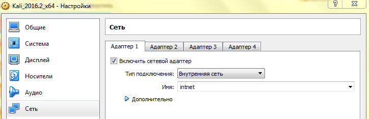
Для начала настроим наши виртуальные машины Kali Linux и Ubuntu Server для работы в одной сети.
Останавливаем машины.
Я хочу, чтобы они работали в виртуальной сети, недоступной для внешнего мира.
Для этого я использую тип подключения «Внутренняя сеть», имя можно оставить стандартное.
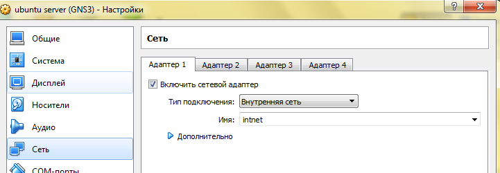
То же саме делаем и для виртуальной машины с установленным GNS3. Следите, чтобы имя сети было тем же.
Я считаю, что очень экономит время, когда в нашей внутренней сети IP адреса раздаются DHCP сервером. Это очень легко сделать при помощи VirtualBox.
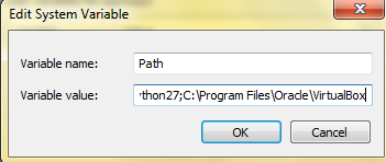
Открываем cmd и выполняем команду
VBoxManage dhcpserver add --netname intnet --ip 192.168.1.0 --netmask 255.255.255.0 --lowerip 192.168.1.1 --upperip 192.168.1.254 –enable
Если команда VBoxManage не распознается, значит, вы забыли прописать путь в переменной окружения PATH.
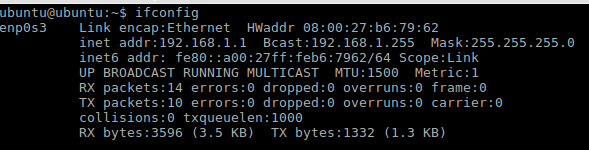
Запускаем обе машины.
Проверяем, раздались ли IP адреса
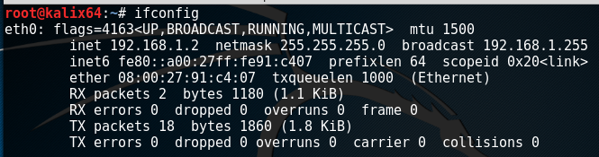
root@kalix64:~# ping 192.168.1.1

PING 192.168.1.1 (192.168.1.1) 56(84) bytes of data.

64 bytes from 192.168.1.1: icmp_seq=1 ttl=64 time=1.07 ms

64 bytes from 192.168.1.1: icmp_seq=2 ttl=64 time=0.552 ms

64 bytes from 192.168.1.1: icmp_seq=3 ttl=64 time=0.987 ms
Как видим, машины видят друг друга.
Запускаем GNS3
Пришло время добавить наш роутер в сеть. Запускаем gns3 на хосте Ubuntu server. После запуска выбираем Local, а не GNS3 VM. На вопрос о добавлении роутера отвечаем отрицательно.
Создаем проект.
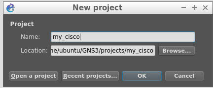
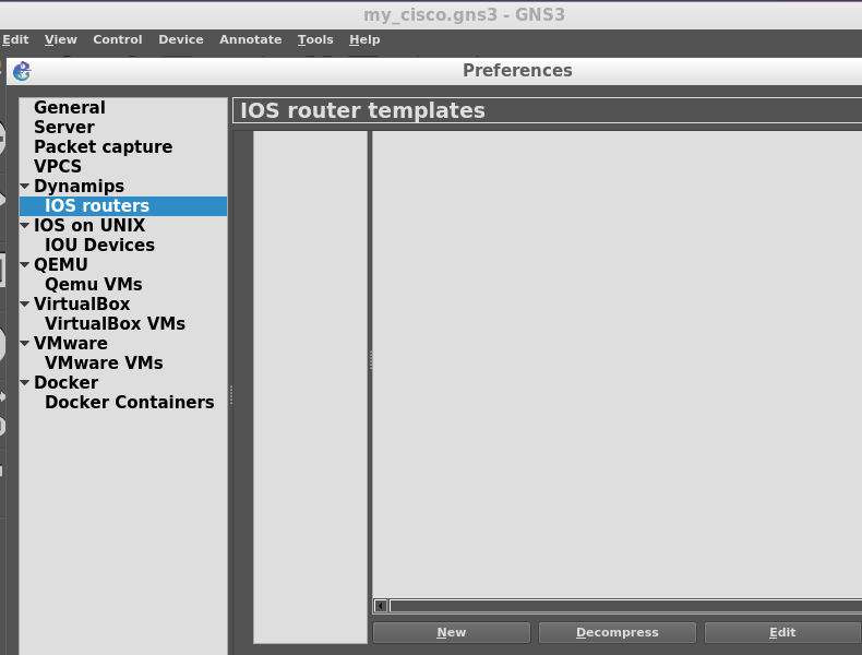
Заходим в настройки Edit=>Preferences
Будем загружать IOS образ. Выбираем IOS routers и жмем New
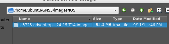
Выбираем New image и жмем Browse, указываем iso файл с образом и жмем Оpen.
Далее нам будет предложено изменить имя роутера, имя платформы, объем RAM. Все это можно оставить без изменения.
На странице с выбором Slot стоит выбрать доступный FE (Fast-Ethernet) модуль. У меня это модуль GT96100-FE
WIC-интерфейс не указываем. Idle-PC оставляем без изменений.
Жмем Finish и выходим из настроек GNS3.
На панели слева нажимаем большую кнопку Browse Routers и видим на панели Routers добавленный нами роутер.
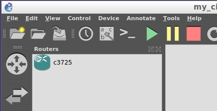
Хватаем и перетаскиваем его на поле справа
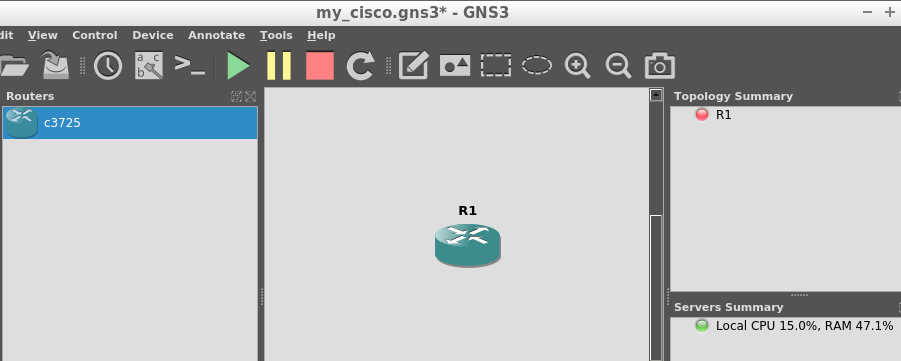
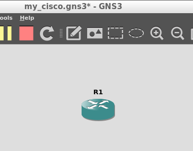
Я оставил название без изменения – R1
Справа, в секции Topology Summary мы видим, что R1 горит красным, что означает, что наш роутер выключен. Скоро мы исправим это.
Настройка роутера в GNS3
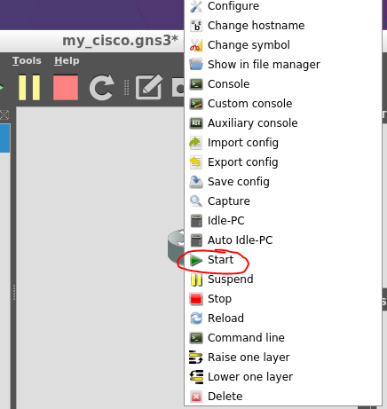
Кликаем правой кнопкой на роутер и выбираем Start.
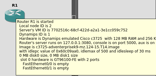
Значок в Topology summary должен позеленеть. Наводим курсор на роутер и видим, что консольный порт у нас 5000
Давайте подключимся к нему. Открываем консоль и выполняем
telnet 127.0.0.1 5000
получаем строку приглашения
Давайте посмотрим, какие интерфейсы у нас доступны
R1#sh ip interface brief

Interface                  IP-Address      OK? Method Status                Protocol

FastEthernet0/0            unassigned      YES unset  administratively down down

FastEthernet0/1            unassigned      YES unset  administratively down down
У нас есть два интерфейса, оба, пока, в выключенном состоянии.
Давайте включим интерфейс FastEthernet0/1 и присвоим ему IP из нашей подсети.
R1#config t
Enter configuration commands, one per line. End with CNTL/Z.
R1(config)#interface fa0/1
R1(config-if)#ip addr
R1(config-if)#ip add 192.168.1.200 255.255.255.0
R1(config-if)#no shut
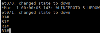
*Mar 1 00:05:23.983: %LINK-3-UPDOWN: Interface FastEthernet0/0, changed state to up
*Mar 1 00:05:24.983: %LINEPROTO-5-UPDOWN: Line protocol on Interface FastEthernet0/1, changed state to up
R1(config-if)#end
R1#
*Mar 1 00:05:53.055: %SYS-5-CONFIG_I: Configured from console by console
R1#wr
Building configuration...
[OK]
R1#copy running-config startup-config
Destination filename [startup-config]?
Building configuration…
Проверим статус интерфейса
R1#sh ip interface brief

Interface IP-Address OK? Method Status Protocol

FastEthernet0/0 unassigned YES unset administratively down down

FastEthernet0/1 192.168.1.200 YES manual up up
Хорошо, интерфейс получил IP, но давайте взглянем на нашу топологию в GNS3
Выглядит так, будто наш роутер никак не связан с чем-либо.
Так оно и есть. Интерфейсу присвоен IP, но сам интерфейс ни к чему не подключен.
Давайте исправим это недоразумение.
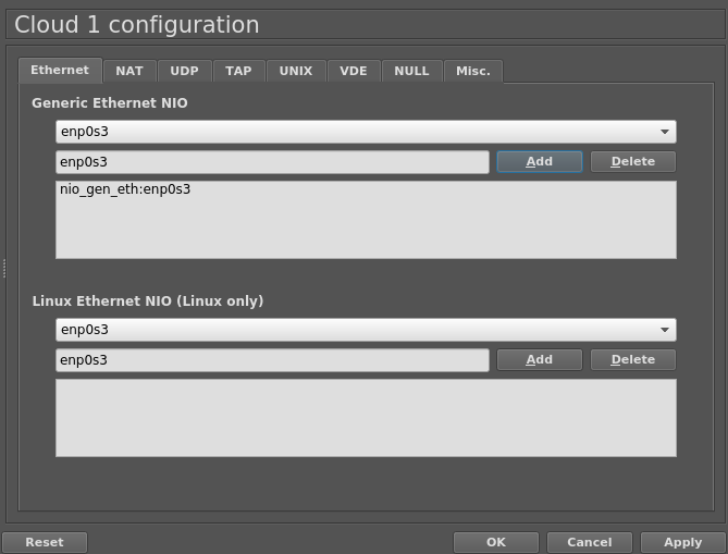
Добавляем в нашу топологию объект Cloud
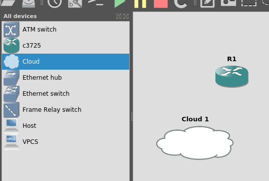
Нажимаем правой кнопкой и выбираем Configure.
Нам предлагается присвоить один из интерфейсов.
Generic Ethernet NIO отличается от Linux Ethernet NIO лишь реализацией на уровне кода (использованием библиотеки pcap или нет). Я выбираю Generic Ethernet NIO и добавляю адаптер, который подключен к виртуальной сети 192.168.1.0/24. Жмем ОК и выходим из режима редактирования.
В левой части главного окна выбираем Add a link

Курсор примет крестообразный вид.
Левой кнопкой мыши кликаем на облаке и выбираем интерфейс, далее кликаем на роутере и выбираем сконфигурированный нами FastEthernet 0/1
Должна получиться такая картина.
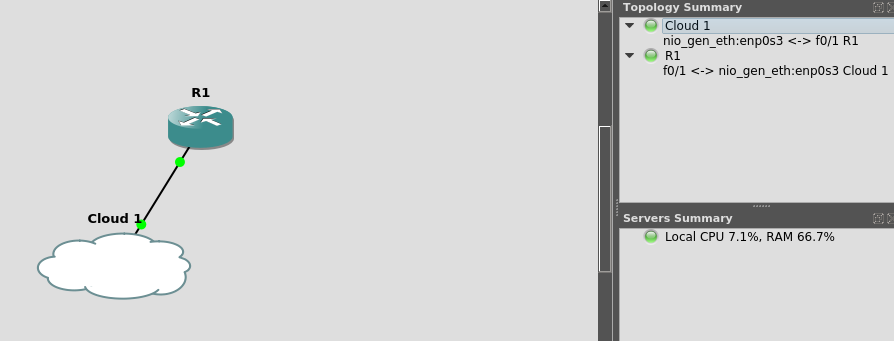
На техническом уровне подключение к облаку, грубо говоря, равнозначно подключению роутера в коммутатор, к которому были бы подключены и наши виртуальные машины.
Давайте попробуем пропинговать наш роутер с Kali.
Не работает. Давайте разбираться, что происходит с нашими пакетами.
Для наглядности я запустил wireshark, чтобы посмотреть, что происходит при выполнении команды ping.
Как видим на скриншоте ниже, выполняется широковещательный ARP-запрос и ищется владелец IP-адреса 192.168.1.200.
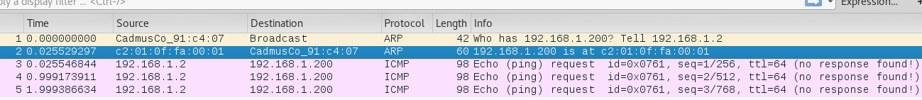
Сетевой интерфейс виртуальной машины Ubuntu server, получив такой пакет отвечает на его MAC-адресом cisco-роутера
MAC-адрес правильный, его мы можем проверить в конфигурации роутера R1.
Так же сервер Ubuntu отвечает и на свой ARP запрос по IP 192.168.1.1
![]()
Получается что-то вроде виртуальных интерфейсов в Linux-системах.
Если запустить wireshark на Ubuntu server, мы не увидим никаких пакетов, кроме широковещательных ARP-запросов и CDP-пакетов.
ICMP пакеты почему-то не проходят.
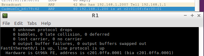
Давайте разбираться. По сути, наш роутер «прячется» за интерфейсом с MAC-адресом 08:00:27:b6:79:62, хоть и имеет MAC-адрес c2:01:0f:fa:00:01.
В обычном режиме работы сетевой интерфейс принимает все пакеты, предназначающиеся своему MAC-адресу и широковещательные пакеты с адресом назначения ff:ff:ff:ff:ff:ff (которыми являются ARP-запросы).
Получается, наш интерфейс должен принимать пакеты, как со своим MAC-адресом, так и с MAC-адресом роутера.
Похоже, что пакет, с MAC-адресом роутера отбрасывается, т.к. не предназначается непосредственно интерфейсу виртуальной машины. Нужно заставить ОС принять этот пакет, чтобы позволить ему обработаться нашим роутером на сетевом уровне (пакет отбрасывается уже на канальном уровне).
Для этого нужно, чтобы наш интерфейс работал в так называемом «неразборчивом режиме» (обрабатывал все пакеты, даже если они не предназначены MAC-адресу сетевого интерфеса хоста.)
Для этого в настройках виртуальной машины Ubuntu Server ставим соответствующую настройку
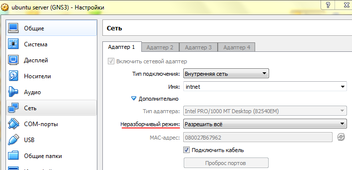
Перезапускаем виртуальную машину.
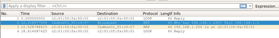
Пробуем пропинговать снова.
Работает! Wireshark так же указывает нам, что приходят ICMP-ответы

Настройка доступа по SSH
Мы настроим доступ по SSH и активируем SNMP, чтобы убедиться в том, что наш роутер не только виден в сети, но и ведет себя как настоящий.
Теперь наш роутер доступен для сети 192.168.1.0/24
Просканировав порты nmap, мы видим, что открыт доступ по telnet
root@kalix64:~# nmap -n -sS -T5 192.168.1.200

Starting Nmap 7.25BETA2 ( https://nmap.org ) at 2016-09-14 11:35 EDT

Nmap scan report for 192.168.1.200

Host is up (0.13s latency).

Not shown: 999 closed ports

PORT   STATE SERVICE

23/tcp open  telnet

MAC Address: C2:01:0F:FA:00:01 (Unknown)
Это не очень безопасно, так что лучше заменить telnet на SSH.
Подключаемся к роутеру с Ubuntu Server и настраиваем.
R1#conf t

Enter configuration commands, one per line.  End with CNTL/Z.

R1(config)#ip domain name cisco.vbox

R1(config)#crypto key generate rsa

The name for the keys will be: R1.cisco.vbox

Choose the size of the key modulus in the range of 360 to 2048 for your

General Purpose Keys. Choosing a key modulus greater than 512 may take

a few minutes.

How many bits in the modulus [512]: 2048

% Generating 2048 bit RSA keys, keys will be non-exportable...[OK]

*Mar  1 00:05:53.339: %SSH-5-ENABLED: SSH 1.9 has been enabled

R1(config)#service password-encryption

R1(config)#username user privilege 15 password Pa$$w0rd

R1(config)#aaa new-model

R1(config)#line vty 0 4

R1(config-line)#transport input ssh

R1(config-line)#logging synchronous

R1(config-line)#exec-timeout 60 0

R1(config-line)#privilege level 15

R1(config-line)#exit

R1(config)#ip ssh version 2

R1#wr

R1#copy running-config sta

R1#copy running-config startup-config

Destination filename [startup-config]?

Building configuration...

[OK]
Снова сканируем nmap
root@kalix64:~# nmap -n -sS -T5 192.168.1.200

Starting Nmap 7.25BETA2 ( https://nmap.org ) at 2016-09-14 11:40 EDT

Nmap scan report for 192.168.1.200

Host is up (0.13s latency).

Not shown: 999 closed ports

PORT   STATE SERVICE

22/tcp open  ssh

MAC Address: C2:01:0F:FA:00:01 (Unknown)
Попробуем подключиться
root@kalix64:~# ssh -oKexAlgorithms=+diffie-hellman-group1-sha1 user@192.168.1.200

Password:

R1>
К сожалению, как я понял, мой роутер поддерживает устаревший алгоритм diffie-hellman-group1-sha1, так что, метод, описанный здесь не претендует на использование в боевых условиях , а лишь показывает пример настройки.
Подробнее можно прочитать тут:
http://www.openssh.com/legacy.html
Активация SNMP
CDP-пакеты вы уже могли видеть на скриншотах wireshark, так что осталось лишь настроить SNMP.
Логинимся на роутер по SSH.
R1>sh snmp

%SNMP agent not enabled
Как видим, SNMP не настроен.
Настраиваем.
R1#conf t

Enter configuration commands, one per line. End with CNTL/Z.

R1(config)#snmp-server community public RO

R1(config)#snmp-server community private RW

R1(config)#exit

R1#wr

R1# copy running-config startup-config

R1>sh snmp

R1#sh snmp

Chassis: FTX0945W0MY

0 SNMP packets input

0 Bad SNMP version errors

0 Unknown community name

0 Illegal operation for community name supplied

0 Encoding errors

0 Number of requested variables

0 Number of altered variables

0 Get-request PDUs

0 Get-next PDUs

0 Set-request PDUs

0 Input queue packet drops (Maximum queue size 1000)

0 SNMP packets output

0 Too big errors (Maximum packet size 1500)

0 No such name errors

0 Bad values errors

0 General errors

0 Response PDUs

0 Trap PDUs

SNMP Trap Queue: 0 dropped due to resource failure.

SNMP logging: disabled
Проверяем открыт ли теперь 161 порт
root@kalix64:~# nmap -n -sU -p 161 192.168.1.200

Starting Nmap 7.25BETA2 ( https://nmap.org ) at 2016-09-15 05:36 EDT

Nmap scan report for 192.168.1.200

Host is up (0.0083s latency).

PORT STATE SERVICE

161/udp open snmp

MAC Address: C2:01:0F:FA:00:01 (Unknown)

Nmap done: 1 IP address (1 host up) scanned in 0.10 seconds
Порт доступен и мы можем работать с роутером по протоколу SNMP.
Заключение
При помощи GNS3 можно создавать гораздо более сложные топологии, подключать ваши виртуальные роутеры к реальным сетям и Интернет. Применений можно найти массу. GNS3 доступна не только для Linux, но и для Windows и MAC.
Спасибо за внимание и до новых встреч!
Добрый день дорогие друзья. Извиняюсь что так долго не писал, только на прошлой недели выписался из больницы после почти трехнедельного пребывания в ней, но слава богу это заточение закончилось и сегодня мы с вами познакомимся с еще одним симулятором сетей – а именно с GNS 3.
Наверное, у вас может появиться резонный вопрос: а зачем нам вообще с ним знакомиться, ведь у нас есть всеми нами любимый Packet Tracer? Вполне обоснованный вопрос, ведь Packet Tracer позволяет воспроизвести примерно 80, а то и больше процентов функционала реальных устройств фирмы Cisco. Но как говорится 80 не 100, и именно симулятор GNS3 позволит нам поковыряться практически во всех оставшихся 20%. Столь близкое приближение симулятора GNS3 к реальным устройствам Cisco происходит из за одной ключевой особенности – данный симулятор способен работать с реальными IOSами от маршрутизаторов фирмы Cisco (GNS3 не предназначен для симуляции коммутаторов фирмы Cisco), а значит мы можем грубо говоря взять IOS от реальной железки, запихнуть его в GNS3 и получить доступ к консоли виртуального маршрутизатора, обладающего всеми функциями реального. Кроме того GNS3 имеет еще одну очень интересную особенность, он позволяет соединить виртуальную сеть, спроектированную в нем, с реальной сетью, но об этом чуть позже, а пока что познакомимся с азами работы с данными симулятором.
Начнем с того, что скачать последнюю версию GNS3 вы можете по данной ссылке: http://www.gns3.net/download/. После довольно таки простой установки и запуска перед нами предстает вот такое главное окно программы:
 |
| Внешний вид окна симулятора GNS3 |
В принципе оно имеет довольно стандартный вид. Сверху меню, слева набор устройств в центре рабочая область. Логично предположить, что требуется перетащить устройства в рабочую область, соединить их, поковыряться в настройках и радоваться жизни. Но на самом деле все не так просто. Если вы попробуете перетащить один из имеющихся на левой панели маршрутизаторов на рабочую область, то получить сообщение вида:
 |
| Сообщение в GNS3 |
Как мы уже говорили ранее, GNS3 работает с реальными IOSами маршрутизаторов фирмы Cisco, но есть одна загвоздочка, эти самые IOSы не идут в комплекте поставки GNS3, так как они стоят денег и соответственно просто так их никто распространять не будет (Но в этой стране это далеко не проблема и при большом желании используя в поисковом запросе ключевые слова типа Cisco + ios + номер серии маршрутизатора + torrent можно в течении 15 минут раздобыть данный образ). Следовательно для того чтобы использовать GNS3 нам сначала необходимо раздобыть образы операционных систем устройств, которые мы хотим симулировать.
Допустим у нас есть данный образ, что дальше? Далее нам необходимо добавить маршрутизатор, работающий на данном IOSe в GNS3. Для этого в главном меню нажимаем на пункт Edit – IOS images and hypervisors. После чего перед нами откроется вот такое прекрасное окно:
 |
| Добавляем образ маршрутизатора в GNS3 |
В данном окне в поле Image file указываем путь к нашему IOSу (путь не должен содержать русские символы), в поле Base config указываем текстовый файл, содержащий конфигурацию маршрутизатора (Если вы хотите чтобы маршрутизатор запустился со стандартной пустой конфигурацией, то не трогайте это поле). Поля Platform, Model и Default Ram автоматически сконфигурируются в соответствие с выбранным вами IOSом. Далее нажимаем на кнопку Save, после чего образ нашего маршрутизатора появится в верхней части окна, в которой перечислены образы доступные для симуляции. После этого окно добавления образа можно закрыть.
После этого перетащите из панели Node Types, появившийся там образ вашего маршрутизатора в рабочую область. Если все сделано верно, и образ добавлен правильно, то никаких ошибок не должно возникнуть и в рабочей области окажется маршрутизатор, все это будет выглядеть следующим образом:
 |
| Маршрутизатора в рабочей области GNS3 |
Для того чтобы запустить ваш маршрутизатор, щелкните по нему правой кнопкой мыши и выберите пункт Start. Через некоторое время, зависящее от производительности вашего ПК, маршрутизатор запустится. А его значок на панели Topology Summary позеленеет. После этого можно получить доступ непосредственно к консоли маршрутизатора. Для этого щелкните по маршрутизатору правой кнопкой мыши и выберите пункт Console. В результате откроется окно консоли:
 |
| Консоль маршрутизатора, запущенного в GNS3 |
Собственно говоря с помощью данной консоли вы можете приступить к конфигурированию своего маршрутизатора и поковыряться в его настройках. Об остальных возможностях GNS3 мы поговорим в следующих статьях.
After installing GNS3, you need to add router IOS image in GNS3. To do so, you need to perform the following steps:
-
In the GNS3 console, click Edit and select Preferences to open the Preferences window. Click Next to add a new router IOS image in GNS3, as shown in the following figure.

-
In the IOS image page, select the New Image radio button, click Browse and select the router IOS image that you want to add in GNS3. In this case, e will use Cisco router c2691 IOS image. Click Next to proceed, as shown in the following figure.

-
In the Name and platform window, specify the name and platform for the IOS image and then click Next as shown in the following figure.

-
In the Memory page, set the desired Default RAM size and then click Next as shown in the following figure.

-
In the Network adapters page, ensure that slot 0 is already listed and selected. Select the additional slots, if required, and then click Next as shown in the following figure.

-
In the WIC modules page, select the WIC modules to add additional modules as per your requirement, and then click Next as shown in the following figure.

-
On the Idle-pc page, click Finish and then click OK to close the Preferences window.
-
In the GNS3 console, you can see that c2691 router is added. Drag it to the work view area as shown in the following figure. Right-click on the added router and then select Start to start it.

-
Open the console of the router as shown in the following figure.

Source
https://protechgurus.com/how-to-add-router-ios-image-in-gns3/
GNS3 can be used to simulate a network composed exclusively of open-source routers, switches, servers, and hosts.

In this post, we will investigate how well GNS3 works when we use it strictly as an open-source network simulator, without using Cisco or Juniper routers in the simulation.
Build the network in GNS3
We are using VirtualBox to run the Linux virtual machines in our simulated network. When using VirtualBox, we must prepare a VirtualBox virtual machine for each node we will use.
Let’s use the virtual machines we already prepared in the the previous post about setting up GNS3 with virtual Linux routers. In this case, we will have five virtual machines prepared: three hosts and two routers.

After starting GNS3, add three hosts, two routers, one switch, and some ethernet links to create the topology shown below.

To build the topology, click on the Browse all Devices button to show the Devices panel. Use the following devices to create the nodes.
- router-virtualbox
- This is the custom node we created in an earlier post. Use this for the routers Quagga-1 and Quagga-2.
- VirtualBox Guest
- Use this for the host computers Host-1, Host-2, and Host-3.
- Ethernet Switch
- This is a basic switch provided by GNS3. Use it to creat the switch SW1.
Add network devices
First, click on the router-virtualbox device and drag it to the middle panel in the GNS3 window. After you drop it, a dialogue box appears asking which VirtualBox guest will run on this node. Choose the guest, Quagga1, which has a disk image with Tiny Core Linux, Quagga, and Openvswitch installed.

Now a router symbol with the label Quagga1 appears in GNS3.
Repeat this process for each device in the planned topology until we have three hosts, two routers, and one switch arranged as shown below.

Add network links
Click on the Add a Link button to set up links between the nodes in the network. The button will change to show a red stop sign with a white “X”. This indicates we need to click the button again to exit the link-add mode when we are done adding links. GNS3 only supports Ethernet links between VirtualBox virtual machines so we do not need to select the link type. The default link type, GigaEthernet, will work correctly.
To add a link between two nodes, click on the first node, then select the port in the pop-up menu. Then click on the second link and select the port. The link is created. In this case, we will connect the two routers so that the link connects port eth7 on each router. If you are wondering which ports are already used, you can check in the Topology Summary panel in the lower right of the GNS3 window. In the Topology Summary panel, double-click on the node you are interested in to see which ports are already connected.

Now create the network topology shown in the screen capture below. Connect port eth0 on each device to the appropriate network element: Quagga-1, Host-1, and Host-2 all connect to switch SW1; Quagga-2 connects directly to Host-3.

Start the network simulation
Now that we have created the devices and links, we can start the routers and hosts in the network and configure them so we can perform some very basic tests on the networking software on each device.
Click the Start All Devices green arrow button on the GNS3 user interface. All the links will in network diagram turn green. All the nodes listed in the Topology Summary panel will turn green.

Login to all devices
Now, we log into each node using its console window.
You can start a console on any individual node by right-clicking on the node and selecting Console from the drop-down menu; or by clicking on a node and then clicking on the Console button at the top of the GNS3 user interface (it looks like a small terminal screen).
You can start all consoles at the same time by clicking on the Console connect to all devices command in the GNS3 Control menu.
Control → Console connect to all devices
A new terminal window will appear for each virtual machine. Arrange the terminals on your desktop according to your preference. Hit the Enter key on each terminal to get a prompt.
The login for each virtual machine we are using in this example is tc.
box login: tc

Now we are logged into each of the hosts and routers in the network.
Configure the network devices
We can configure each node in the network so that the routers can route traffic from one network to the other and then we will run a few basic tests to verify that the configuration works.
We will configure three networks and set up a dynamic routing protocol, OSPF, that will run on the network connecting the two routers together and pass network information from one router to the next.
Network 10.0.100.0/24
The first network consists of the hosts Host-1 and Host-2 and the router Quagga-1. We will assign this network the network address, 10.0.100.0/24.
On Quagga-1, enter the following commands to start Quagga and use the Quagga command-line-interface to configure the router’s port eth0 with a valid IP address.
$ sudo vtysh
box# configure terminal
box(config)# interface eth0
box(config-if)# ip address 10.0.100.1/24
box(config-if)#  exit
box(config)# exit
box#
On Host-1, enter the following commands to configure the eth0 interface on Host-1 and create a default route toward router Quagga-1 (which in this network has IP adress 10.0.100.1).
$ sudo ip addr add 10.0.100.2/24 broadcast 10.0.100.255 dev eth0
$ sudo ip route add default via 10.0.100.1
On Host-2, enter the following commands to configure the eth0 interface IP address and create a default route.
$ sudo ip addr add 10.0.100.3/24 broadcast 10.0.100.255 dev eth0
$ sudo ip route add default via 10.0.100.1
Now, each node on this network should be reachable by any other node on the same network. Host-1, Host-2, and Quagga-1 can all ping each other.
Network 10.0.200.0/24
The second network consists of the hosts Host-3 and the router Quagga-2. We will assign this network the network address, 10.0.200.0/24.
On Quagga-2, enter the following commands to start Quagga and use the Quagga command-line-interface to configure the router’s port eth0 with a valid IP address.
$ sudo vtysh
box# configure terminal
box(config)# interface eth0
box(config-if)# ip address 10.0.200.1/24
box(config-if)#  exit
box(config)# exit
box#
On Host-3, enter the following commands to configure the eth0 interface on Host-3 and create a default route toward router Quagga-2 (which in this network has IP adress 10.0.200.1).
$ sudo ip addr add 10.0.200.2/24 broadcast 10.0.200.255 dev eth0
$ sudo ip route add default via 10.0.200.1
Network 10.0.1.0/24
The second network consists of the routers Quagga-1 and Quagga-2. We used port eth7 on each router to create the link between them. We will give this network the network address 10.0.1.0/24.
We are already running vtysh on both routers.
On Quagga-1, enter the following commands to configure port eth7, set up OSPF in the network, and to export directly connected network addresses to the OSPF protocol so they can be shared with other routers.
box# configure terminal
box(config)# router ospf
box(config-router)# network 10.0.1.0/24 area 0
box(config-router)# redistribute connected
box(config-router)# exit
box(config)# interface eth7
box(config-if)# ip address 10.0.1.1/24
box(config-if)# exit
box(config)# exit
box#
On Quagga-2, enter the following commands to configure port eth7, set up OSPF in the network, and to export directly connected network addresses to the OSPF protocol so they can be shared with other routers.
box# configure terminal
box(config)# router ospf
box(config-router)# network 10.0.1.0/24 area 0
box(config-router)# redistribute connected
box(config-router)# exit
box(config)# interface eth7
box(config-if)# ip address 10.0.1.2/24
box(config-if)# exit
box(config)# exit
box#
Network configuration completed
Now we are able to pass data from any node on network 10.0.100.0/24 to any node network 10.0.200.0/24. We can verify this by using the ping command to verify that data can pass from Host-1 on network 10.0.100.0/24 to Host-3 on network 10.0.200.0/24.
On Host-1, execute the ping command and see the following results:
$ ping -c 1 10.0.200.2
PING 10.0.200.2 (10.0.200.2): 56 data bytes
64 bytes from 10.0.200.2: seq=0 ttl=62 time=0.000 ms

--- 10.0.200.2 ping statistics ---
1 packets transmitted, 1 packets received, 0% packet loss
round-trip min/avg/max = 0.000/0.000/0.000 ms
We see that traffic will pass in both directions between Host-1 and Host-3 through all three networks in this simulation.
Capture and analyze network traffic
We can set up GNS3 to capture data on any interface in the network. To start a data capture, right-click on a link in the network diagram and then select Start capturing from the drop-down menu1.

Then select which interface on the link you wish to from which you want to capture data. Note that you cannot choose an interface connected to switch SW1; only interfaces connected to running virtual machines can support capturing data.

Restart node to enable data capture
We see an error message pop up that says we must restart the node that has the interface from which you want to capture data before data can be captured. This is an inconvenient feature in GNS3.
To restart the node, right-click on the node Quagga-1 and select Stop in the pop-up menu. At this point we will also add a second data capture point so that we are capturing data on both interfaces on router Quagga-1, eth0 and eth7.
To start the router Quagga-1 again, right-click Quagga-1 and select Start in the pop-up menu. When the node completes starting up, start the console and reconfigure the node as previously described.
Note: When we restart Quagga-1 we lose the configurations we made because the TinyCore Linux appliances provided by the GNS3 project are read-only filesystems. This is related to the Persistence feature of TinyCore Linux that we will discuss, along with a remedy, in a future post. In this case, we will need to enter in all our configurations again for router Quagga-1.
We now know that we should define any data capture points before starting the simulation and configuring the network nodes.
Start Wireshark
Start Wireshark to see the packets at each capture point. To view the data being captured, click on the interface in the Captures panel and then right-click to see the pop-up window. Select Start Wireshark from the menu.

A Wireshark window will open up showing the data that is being captured on that interface. In this case, we are looking at the data captured on the eth7 interface on router Quagga-1. We see OSPF packets being exchanged between Quagga-1 and Quagga-2.

Save the project
The project topology can be saved for future use. Use the following menu command or press the Ctrl-S key combination to save the project.
File → Save Project
Not all information related to the project is saved by GNS3. The data capture points are not saved. When you open the saved project, you must define your data capture points again.
Also, the node configurations are not saved and each node will need to be manually configured again when the saved project is started again. This is because we are using the read-only TinyCore Linux appliances provided by GNS3. In a future post, we will describe a procedure that creates persistent network configurations and saves them on each TinyCore Linux appliance.
Conclusion
We showed how to set up a network in GNS3 using only the open-source appliances provided by the GNS3 project. We demonstrated that the simulated open-source hosts and routers can be configured to pass data between themselves and to route packets from one network to another.
The GNS3 project provides Linux appliances that can be used as Linux switches, routers, and hosts. This makes it easier to use open-source software in GNS3 because the provided appliances are already configured to work correctly with GNS3.
When it is used exclusively to simulate open-source routers and hosts, GNS3 is provides similar functionality to, but is more complex to use, than other open-source network simulators. I understand that I have explored only a small portion of GNS3’s capabilities. GNS3’s main function is to emulate Cisco routers and using only open-source routers is not the normal GNS3 use-case.
-
This screen capture also shows that the GNS3 user interface can be modified by removing panels, or adding panels, as required ↩