Table Of Contents
Connecting Cisco Ethernet, Fast Ethernet, and Token Ring Network Modules to the Network
Ethernet Network Modules
1- and 4-Port Ethernet Modules
Ethernet 2-WAN Card Slot Modules
Ethernet Connectors
Connecting Ethernet Ports
AUI Connections
10BASE-T Connections
Ethernet LEDs
Fast Ethernet Network Modules
1-Port Fast Ethernet Modules
Fast Ethernet 2-WAN Card Slot Modules
Connecting Fast Ethernet Ports
100BASE-T Connections
100BASE-FX Connections
Fast Ethernet LEDs
Token Ring Network Modules
Connecting Token Ring Ports
Token Ring LEDs
Related Documents
Obtaining Documentation, Obtaining Support, and Security Guidelines
Connecting Cisco Ethernet, Fast Ethernet, and Token Ring Network Modules to the Network
Revised: 08/07/2008, OL-12807-01
This guide describes how to connect Cisco Ethernet, Fast Ethernet, and Token Ring network modules to your network. It contains the following sections:
•![]() Ethernet Network Modules
Ethernet Network Modules
•![]() Fast Ethernet Network Modules
Fast Ethernet Network Modules
•![]() Token Ring Network Modules
Token Ring Network Modules
•![]() Related Documents
Related Documents
•![]() Obtaining Documentation, Obtaining Support, and Security Guidelines
Obtaining Documentation, Obtaining Support, and Security Guidelines
Ethernet Network Modules
Ethernet connections are provided on 1- and 4-port Ethernet modules, and on 1-port Ethernet, 2-port Ethernet, and 1-port Ethernet 1-port Token Ring 2-WAN card slot modules.
1- and 4-Port Ethernet Modules
The following network modules provide Ethernet interfaces:
•![]() 1-port Ethernet network module (NM-1E) (see Figure 1)
1-port Ethernet network module (NM-1E) (see Figure 1)
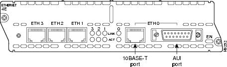
•![]() 4-port Ethernet network module (NM-4E) (see Figure 2)
4-port Ethernet network module (NM-4E) (see Figure 2)
Figure 1 1-Port Ethernet Network Module
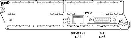
Figure 2 4-Port Ethernet Network Module
Ethernet 2-WAN Card Slot Modules
The following 2-slot network modules provide one or two Ethernet interfaces, plus two slots for optional WAN interface cards:
•![]() 1-Ethernet 2-WAN card slot network module (NM-1E2W) (see Figure 3)
1-Ethernet 2-WAN card slot network module (NM-1E2W) (see Figure 3)
•![]() 2-Ethernet 2-WAN card slot network module (NM-2E2W) (see Figure 4)
2-Ethernet 2-WAN card slot network module (NM-2E2W) (see Figure 4)
•![]() 1-Ethernet 1-Token Ring 2-WAN card slot network module (NM-1E1R2W) (see Figure 5)
1-Ethernet 1-Token Ring 2-WAN card slot network module (NM-1E1R2W) (see Figure 5)
Figure 3 1-Ethernet 2-WAN Card Slot Network Module
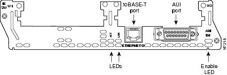
Figure 4 2-Ethernet 2-WAN Card Slot Network Module
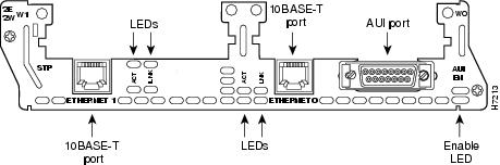
Figure 5 1-Ethernet 1-Token Ring 2-WAN Card Slot Network Module
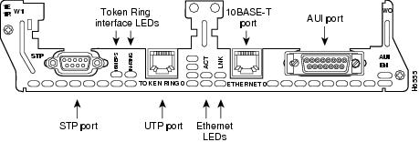
Ethernet Connectors
The 1-port Ethernet network module, the 1-Ethernet 2-slot network module, and the 1-Ethernet 1-Token Ring 2-slot network module each provide a single Ethernet port. This port uses either the attachment unit interface (AUI) DB-15 connector on the right side of the module or the 10BASE-T (RJ-45) connector next to it. Only one of these connectors can be active at a time. The active port is identified in software by port type (Ethernet), slot number on the module, and port number 0.
All modules detect the type of network connection automatically, and you do not need to choose the media type in software. If cables are plugged into both ports, the 10BASE-T connection is chosen.
The 4-port Ethernet network module has ports for four Ethernet connections (0, 1, 2, and 3). Port 0 offers a choice of an AUI or 10BASE-T interface. Ethernet ports 1, 2, and 3 use 10BASE-T connectors only. These ports do not provide an AUI connector.
The 2-Ethernet 2-slot network module has ports for two Ethernet connections. Port 0 offers a choice of AUI or 10BASE-T. Port 1 uses 10BASE-T only.
Connecting Ethernet Ports
If an Ethernet port offers both an AUI connector and a 10BASE-T connector, you can use either connector, but not both at the same time.
AUI Connections
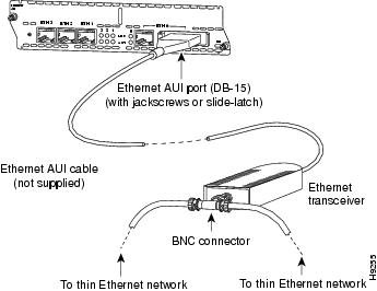
Use an Ethernet AUI cable to connect an AUI port to an Ethernet transceiver. These ports are color-coded yellow. The female end of the AUI cable mates with the slide-latch connector of the transceiver cable. Figure 6 shows a thin Ethernet transceiver as an example, but you can use any type of Ethernet transceiver.
If the transceiver cable has thumbscrew connectors, you can connect it directly to the AUI port by replacing the AUI port slide latch with a jackscrew (provided in a separate bag).
Figure 6 Connecting an Ethernet AUI Port to a Transceiver
10BASE-T Connections
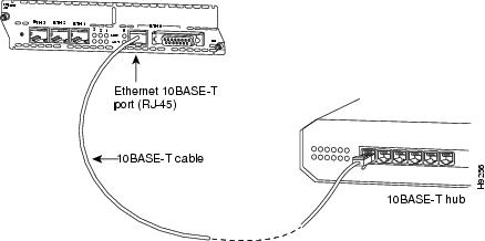
Use an Ethernet 10BASE-T cable to connect a 10BASE-T port to a hub or other network device. These ports are color-coded yellow. Figure 7 shows the 10BASE-T port on an Ethernet network module connected to a hub.
Figure 7 Connecting an Ethernet 10BASE-T Port to a Hub
Ethernet LEDs
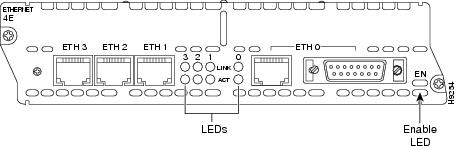
This section describes Ethernet module LEDs. Figure 8 shows 4-port Ethernet network module LEDs as an example.
All network modules have an enable (EN) LED. This LED indicates that the module has passed its self-tests and is available to the router.
Each Ethernet port has two LEDs. The activity (ACT) LED indicates that the router is sending or receiving Ethernet transmissions. The link (LINK) LED indicates that the Ethernet port is receiving the link integrity signal from the hub (10BASE-T only).
Figure 8 Ethernet Network Module LEDs (Typical)
Fast Ethernet Network Modules
Fast Ethernet connections are provided on 1-port Fast Ethernet modules, and on 1-port Fast Ethernet, 2-port Fast Ethernet, and 1-port Fast Ethernet 1-port Token Ring 2-WAN card slot modules.
1-Port Fast Ethernet Modules
The following network modules provide Fast Ethernet interfaces:
•![]() 1-port Fast Ethernet network module with TX connector, Cisco product number NM-1FE-TX. (See Figure 9.) This module provides an RJ-45 connector for direct connection to 100BASE-T Ethernet networks.
1-port Fast Ethernet network module with TX connector, Cisco product number NM-1FE-TX. (See Figure 9.) This module provides an RJ-45 connector for direct connection to 100BASE-T Ethernet networks.
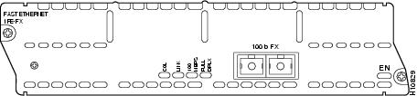
•![]() 1-port Fast Ethernet network module with FX connector, Cisco product number NM-1FE-FX. (See Figure 10.) This module provides a duplex SC-type fiber-optic port for direct connection to 100BASE-FX Ethernet networks.
1-port Fast Ethernet network module with FX connector, Cisco product number NM-1FE-FX. (See Figure 10.) This module provides a duplex SC-type fiber-optic port for direct connection to 100BASE-FX Ethernet networks.
Figure 9 1-Port Fast Ethernet Network Module (TX Connector)
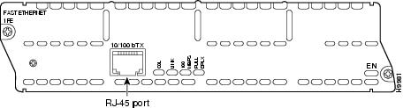
Figure 10 1-Port Fast Ethernet Network Module (FX Connector)
Fast Ethernet 2-WAN Card Slot Modules
The following 2-slot network modules provide one or two 100BASE-T Fast Ethernet interfaces, plus two slots for optional WAN interface cards:
•![]() 1-Fast Ethernet 2-WAN card slot network module (NM-1FE2W and NM-1FE2W-V2). See Figure 11 for a sample faceplate.
1-Fast Ethernet 2-WAN card slot network module (NM-1FE2W and NM-1FE2W-V2). See Figure 11 for a sample faceplate.
•![]() 2-Fast Ethernet 2-WAN card slot network module (NM-2FE2W and NM-2FE2W-V2). See Figure 12 for a sample faceplate.
2-Fast Ethernet 2-WAN card slot network module (NM-2FE2W and NM-2FE2W-V2). See Figure 12 for a sample faceplate.
•![]() 1-Fast Ethernet 1-Token Ring 2-WAN card slot network module (NM-1FE1R2W and NM-1FE1R2W-V2). See Figure 13 for a sample faceplate.
1-Fast Ethernet 1-Token Ring 2-WAN card slot network module (NM-1FE1R2W and NM-1FE1R2W-V2). See Figure 13 for a sample faceplate.

Caution
![]() To comply with the Telcordia GR-1089 NEBS standard for electromagnetic compatibility and safety, connect the 1-Fast Ethernet 2-WAN card slot network modules (NM-1FE2W-V2, NM-1FE2W), the 2-Fast Ethernet 2-WAN card slot network modules (NM-2FE2W-V2, NM-2FE2W), the 2 WAN Card Slot Network Module (NM-2W)and the 1-Fast Ethernet 1-Token Ring 2-WAN card slot network modules (NM-1FE1R2W) only to intrabuilding or nonexposed wiring or cabling. The intrabuilding cable must be shielded and the shield must be grounded at both ends. The intra-building port(s) of the equipment or subassembly must not be metallically connected to interfaces that connect to the OSP or its wiring. These interfaces are designed for use as intra-building interfaces only (Type 2 or Type 4 ports as described in GR-1089-CORE, Issue 4) and require isolation from the exposed OSP cabling. The addition of Primary Protectors is not sufficient protection in order to connect these interfaces metallically to OSP wiring.
To comply with the Telcordia GR-1089 NEBS standard for electromagnetic compatibility and safety, connect the 1-Fast Ethernet 2-WAN card slot network modules (NM-1FE2W-V2, NM-1FE2W), the 2-Fast Ethernet 2-WAN card slot network modules (NM-2FE2W-V2, NM-2FE2W), the 2 WAN Card Slot Network Module (NM-2W)and the 1-Fast Ethernet 1-Token Ring 2-WAN card slot network modules (NM-1FE1R2W) only to intrabuilding or nonexposed wiring or cabling. The intrabuilding cable must be shielded and the shield must be grounded at both ends. The intra-building port(s) of the equipment or subassembly must not be metallically connected to interfaces that connect to the OSP or its wiring. These interfaces are designed for use as intra-building interfaces only (Type 2 or Type 4 ports as described in GR-1089-CORE, Issue 4) and require isolation from the exposed OSP cabling. The addition of Primary Protectors is not sufficient protection in order to connect these interfaces metallically to OSP wiring.
Figure 11 1-Fast Ethernet 2-WAN Card Slot Network Module
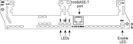
Figure 12 2-Fast Ethernet 2-WAN Card Slot Network Module
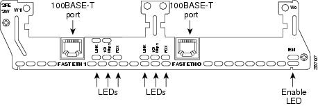
Figure 13 1-Fast Ethernet 1-Token Ring 2-WAN Card Slot Network Module
Connecting Fast Ethernet Ports
Use the following sections for 100BASE-T or 100BASE-FX connections.
100BASE-T Connections
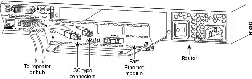
Use a two-pair Category 5 or unshielded twisted-pair (UTP) straight-through RJ-45 cable to connect a Fast Ethernet RJ-45 port to a switch, hub, repeater, server, or other network device. Figure 14 shows an RJ-45 port connected to a hub.

Note ![]() RJ-45 cables are not available from Cisco Systems. These cables are widely available and must be Category 5 cables.
RJ-45 cables are not available from Cisco Systems. These cables are widely available and must be Category 5 cables.
Figure 14 Connecting a Fast Ethernet RJ-45 Port to a Hub

100BASE-FX Connections
Attach a multimode fiber-optic cable with SC-type connectors directly to the port on the Fast Ethernet network module (remove the protective plug from the port if it is present). Use either one duplex SC connector (see Figure 15 and Figure 17) or two simplex SC connectors (see Figure 16 and Figure 18). Attach the other end of the cable to a repeater, hub, or wall outlet. Be sure to observe the correct relationship between the receive (RX) and transmit (TX) ports on the network module and the cable.
Note ![]() Multimode SC-type fiber-optic cables are widely available commercially. Cisco Systems does not supply these cables.
Multimode SC-type fiber-optic cables are widely available commercially. Cisco Systems does not supply these cables.
Figure 15 Duplex SC Connector
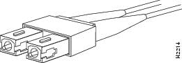
Figure 16 Simplex SC Connector
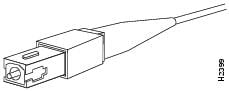
Figure 17 Connecting a Fast Ethernet FX Port to a Repeater or Hub (Duplex Connector)
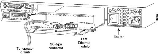
Figure 18 Connecting a Fast Ethernet FX Port to a Repeater or Hub (Simplex Connectors)
Fast Ethernet LEDs
This section describes Fast Ethernet module LEDs. Figure 19 shows 1-port Fast Ethernet network module LEDs as an example.
Figure 19 1-Port Fast Ethernet Network Module LEDs
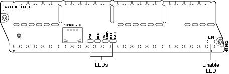
All network modules have an enable (EN) LED. The enable LED indicates that the module has passed its self-tests and is available to the router.
Fast Ethernet network modules have the additional LEDs shown in Table 1.
|
LED |
Meaning |
|---|---|
|
COL |
Collision activity is occurring on the network. |
|
LINK |
A link has been established with the station at the other end of the cable. |
|
100MBPS |
Speed of the interface is 100 Mbps. |
|
FULL DPLX |
Interface is in full-duplex mode. |
Token Ring Network Modules
The following network modules provide Token Ring interfaces:
•![]() 1-port Ethernet 1-port Token Ring 2-WAN card slot module (NM-1E1R2W) (see Figure 20)
1-port Ethernet 1-port Token Ring 2-WAN card slot module (NM-1E1R2W) (see Figure 20)
•![]() 1-port Fast Ethernet 1-port Token Ring 2-WAN card slot module (NM-1FE2R2W) (see Figure 21)
1-port Fast Ethernet 1-port Token Ring 2-WAN card slot module (NM-1FE2R2W) (see Figure 21)
Figure 20 1-Ethernet 1-Token Ring 2-WAN Card Slot Network Module
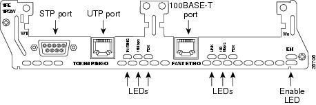
Figure 21 1-Fast Ethernet 1-Token Ring 2-WAN Card Slot Network Module
Connecting Token Ring Ports
The 1-Ethernet 1-Token Ring 2-WAN card slot network module and the 1-Fast Ethernet 1-Token Ring 2-WAN card slot network module each have one DB-9 connector for an STP Token Ring connection and one RJ-45 connector for a UTP Token Ring connection. Only one connector can be active at a time.
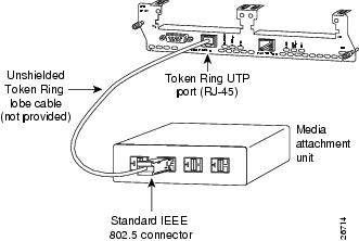
To connect the module to a Token Ring network, attach one end of a shielded Token Ring lobe cable to the DB-9 connector on the network module (see Figure 22), or attach one end of an unshielded Token Ring lobe cable to the UTP connector on the network module (see Figure 23). Attach the other end of the cable to the Token Ring media attachment unit (MAU). The network module automatically detects which connector is in use.
Figure 22 Connecting a Token Ring STP Port (DB-9) to a MAU
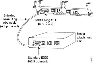
Figure 23 Connecting a Token Ring UTP Port (RJ-45) to an MAU
Token Ring LEDs
All network modules have an enable (EN) LED. The enable LED indicates that the module has passed its self-tests and is available to the router.
The 1-Ethernet 1-Token Ring 2-WAN card slot network module and the 1-Fast Ethernet 1-Token Ring 2-WAN card slot network module both have the following Token Ring LEDs:
•![]() The 16MBPS LED indicates a ring speed of 16 Mbps. If it is off, the ring speed is 4 Mbps.
The 16MBPS LED indicates a ring speed of 16 Mbps. If it is off, the ring speed is 4 Mbps.
•![]() The IN-RING LED indicates that the Token Ring interface is inserted into the ring. If it is off, the interface is not inserted into the ring.
The IN-RING LED indicates that the Token Ring interface is inserted into the ring. If it is off, the interface is not inserted into the ring.
The 1-Fast Ethernet 1-Token Ring 2-slot network module also has the FDX LED, which indicates full-duplex mode.

Timesaver ![]() When the IN-RING LED is off, you can unplug the Token Ring cable without causing a problem on the ring.
When the IN-RING LED is off, you can unplug the Token Ring cable without causing a problem on the ring.
Related Documents
For additional information, see the following documents and resources.
Obtaining Documentation, Obtaining Support, and Security Guidelines
For information on obtaining documentation, obtaining support, providing documentation feedback, security guidelines, and also recommended aliases and general Cisco documents, see the monthly What’s New in Cisco Product Documentation, which also lists all new and revised Cisco technical documentation, at:
http://www.cisco.com/en/US/docs/general/whatsnew/whatsnew.html
CCDE, CCENT, Cisco Eos, Cisco Lumin, Cisco Nexus, Cisco StadiumVision, Cisco TelePresence, the Cisco logo, DCE, and Welcome to the Human Network are trademarks; Changing the Way We Work, Live, Play, and Learn and Cisco Store are service marks; and Access Registrar, Aironet, AsyncOS, Bringing the Meeting To You, Catalyst, CCDA, CCDP, CCIE, CCIP, CCNA, CCNP, CCSP, CCVP, Cisco, the Cisco Certified Internetwork Expert logo, Cisco IOS, Cisco Press, Cisco Systems, Cisco Systems Capital, the Cisco Systems logo, Cisco Unity, Collaboration Without Limitation, EtherFast, EtherSwitch, Event Center, Fast Step, Follow Me Browsing, FormShare, GigaDrive, HomeLink, Internet Quotient, IOS, iPhone, iQ Expertise, the iQ logo, iQ Net Readiness Scorecard, iQuick Study, IronPort, the IronPort logo, LightStream, Linksys, MediaTone, MeetingPlace, MeetingPlace Chime Sound, MGX, Networkers, Networking Academy, Network Registrar, PCNow, PIX, PowerPanels, ProConnect, ScriptShare, SenderBase, SMARTnet, Spectrum Expert, StackWise, The Fastest Way to Increase Your Internet Quotient, TransPath, WebEx, and the WebEx logo are registered trademarks of Cisco Systems, Inc. and/or its affiliates in the United States and certain other countries.
All other trademarks mentioned in this document or Website are the property of their respective owners. The use of the word partner does not imply a partnership relationship between Cisco and any other company. (0807R)
Any Internet Protocol (IP) addresses used in this document are not intended to be actual addresses. Any examples, command display output, and figures included in the document are shown for illustrative purposes only. Any use of actual IP addresses in illustrative content is unintentional and coincidental.
© 2008 Cisco Systems, Inc. All rights reserved.

Configuring and checking router interfaces are the main tasks of a network engineer, whether it’s the initial configuration of a router or trouble shooting the network connectivity.
In this tutorial you will learn:
- How to configure serial interface of a Cisco router.
- How to configure Fast Ethernet interface of a Cisco Router.
- And How to Enable an interface of Cisco router.
There is a command which displays all the IP interfaces, which is helpful in troubleshooting and knowing the IP address used on a specific interface.
Show ip interface brief // this is an enable/privileged mode command.
You have to be at the enable mode/privileged mode for executing this command, this command can also be used to know if an interface is enabled or administratively down.
How to find Cisco router IP addresses:
IP addresses of each functional and configured interface of a router must be different, “show ip interface brief” command will display all the configured interfaces along with their assigned ip addresses. Open your routers command line interface.
UpaaeRouter1> enable                                 // go to enable mode/ privileged mode.

UpaaeRouter1# show ip interface brief  // display all the ip interface of this router

How to configure Ethernet Interface on Cisco Router:
For configuring any interface of a router you should be at global configuration mode.
Assuming you are at user exe mode.
UpaaeRouter1> enable                                                         // entering to enable/privileged mode

UpaaeRouter1# configure terminal                               // entering to global configuration mode

UpaaeRouter1(config)# interface fastethernet 0/0    //  0/0 specifies the port number

UpaaeRouter1(config-if)# ip address 10.1.1.5   255.0.0.0
Confirm if ip address is assigned successfully.
Switch to enable mode, type “show ip interface brief” command and press enter, just like the screenshot below.

How to configure serial interface on cisco router:
Before executing the commands for setting the ip address for serial interface you need to be at the line configuration mode of that specific interface.
For configuring IP Address for any interface you must be in global configuration mode and then enter to the line configuration mode of required interface. In this case we are going to set ip address for serial 0/0/0 interface. Assuming you are at user exe mode.
UpaaeRouter1> enable // entering enable/privileged mode
UpaaeRouter1# configure terminal // entering global configuration mode
UpaaeRouter1(config)# interface serial 0/0/0 // 0/0/0 specifies the port number
UpaaeRouter1(config-if)# ip address 192.168.1.5 255.255.255.0

Confirming if ip address is assigned successfully.

As you can see that serial interface is properly configured but it is still administratively down, in order to get any interface of cisco router working we need to enable that specific interface.
How to Enable Cisco Router Interface:
By default all of the Cisco router’s interfaces are in down state for security sake, if you want to enable any interface you need to be at the line interface mode, in this example we will enable serial 0/0/0 interface. no shutdown is the command for enabling serial interface.
UpaaeRouter1> enable                                                                  // entering enable/privileged mode

UpaaeRouter1# configure terminal                          // entering global configuration mode

UpaaeRouter1(config)# interface serial 0/0/0        //  0/0/0 specifies the port number

UpaaeRouter1(config-if)# no shutdown            // command for enabling cisco router interface
That’s it, we hope you enjoyed and learned from this tutorial.
Getting a Cisco router up and working is a fairly straightforward endeavor, as there are really only a few items that need to be addressed. Let’s take a look at the basic instructions that will help you configure and setup the router. Once these basic settings are established, the configuration can be made more complex given the individual needs specific to each use.
How to Setup a Cisco Router
When a Cisco router boots for the first time, it will ask if the user would like to review the set of prompts to configure. You can go through these prompts or ignore them and choose to configure the router manually, as most engineers do. Once initially booted, all that is required to configure the router is a USB cable or serial rollover cable. After a connection is made, the initial basic configuration of the device can begin.
Once connected, the user will first see a user exec mode prompt (as long as the user entered ‘no’ in the initial configuration dialog). We need to be in privileged exec mode in order to continue with the configuration. Enter the ‘enable’ command to access this prompt. Once in this mode, the user should be able to access all the commands necessary to alter the configuration of the router. Entering the ‘configuration terminal’ (or ‘conf t’) command will allow the user to do this. This initial config mode is called the Global configuration mode. Here is where domain name, passwords, and the hostname can be configured.
Enter the ‘hostname hostname’ command to configure the hostname of the router. Once entered, the hostname should be reflected in the prefix of the prompt. The domain name can now be configured by entering ‘ip domain-name domain-name’ command.
The user can now move on to setting up the password. Configure the enable password by entering the ‘enable secret password’ command. Setting up the password will prevent unwanted users from getting into privileged exec mode, though it should be known that local users will still be able to access user exec mode.
Setting up interfaces for LAN and WAN
Next, we will cover configuring the Fast Ethernet interfaces for LAN and WAN. Fast Ethernet LAN interfaces are automatically configured as part of the default VLAN, so they are not set up with individual addresses. Access is through the VLAN itself. You can find more information about creating VLANs here.
The procedure for configuring Fast Ethernet WAN interfaces will depend on what model router you are working with. The Cisco 1811 and 1812 routers have two Fast Ethernet interfaces for WAN, while the 1801, 1802, and 1803 routers have one ATM interface for WAN connection.
To configure the Fast Ethernet WAN interface, set up the interface with ‘interface fastethernet number value’. The user can then set the IP address and subnet mask for the specified Fast Ethernet interface with ‘ip address ip address – subnet mask’.
To configure the ATM WAN interface, first enter ‘interface atm0’ to go to the interface configuration mode. Then the user can set the IP address and subnet mask for the ATM interface with ‘ip address ip address – subnet mask’.
One final important step is left: enabling the interface. This can be accomplished by entering ‘no shutdown’ while still in the interface configuration mode.
Configuring command-line access to the router
Access to the router, when connected to the console port, is not password protected by default. This means that any user with physical access will be able to access user exec mode. You can alter this by configuring a password on the console line by entering ‘line console 0’ to enter line configuration mode. Then the user can issue the ‘password password’ command to set the password.
Lastly, we will look at enabling Telnet access to the router. You can configure this access through VTY terminal configuration mode. Most VTY lines used for Telnet connections are labeled 0-4. Enter ‘line vty 0 4’ to access to the mode. From here the user will enter ‘login’ to enable a login prompt that will show when other users are attempting to access the router through the terminal lines. The command ‘password’ will allow us to set the password for this access.
This review of the basic setup instructions for a Cisco router is intended to be a quick reference guide designed to get the device working in a short about of time. For a more thorough review of the setup process, it may be helpful to visit Cisco’s online configuration guide. For more in-depth training classes, see the Cisco training class schedule here.
Have questions? Need guideance? Contact us by email, phone at 913.322.7062 / 314.644.6400, or by completing the following form.
CISCO Systems, Inc was founded in 1984 AD by a two member of Standford University Computer Support staff and now CISCO router is the most used routers in the world. CISCO router is very famous for the security and hence it is used in the high enterprise.
In this tutorial we will see how to assign the IP Address to the Fast Ethernet of the CISCO router. We will learn about the basic command to enter the Global configuration mode where we can write the programme for the router. So let’s get started.,
In this tutorial i will be using CISCO packet tracer as the simulation of all the commands. So before getting started i would like to write few things about the connection between the device.
What Cable will be used for what kinds of Device?
Straight- Through Copper: This wire is used to connect two different device for example router and switch or switch and PC.
Cross Over Cable: This cable is used for connecting two similar kinds of device for example, PC to PC, Router to Router and others
Console Cable: This cable is used for connecting the router or device which is used to be programmed with the PC, for example we use console cable to the Router Console Port and to the PC Rs232.
So you can see below. i have designed the simplest network consisting of PCs, Router, switch and all kinds of cable.
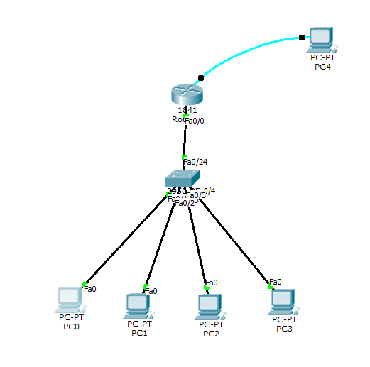
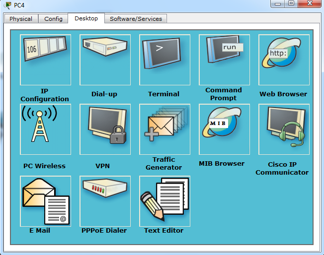
So now, double click on the PC4, in my case case PC4 is connected with router with the console cable.
Click on the desktop and then click on Terminal and then ok
Now you will see the Dialogue box, type no so that you can start programming.
Press Return/Enter Key to get started
Router>!This mode is called user execution Mode
Router>!To go to User privileged mode type Enable
Router>enable
Router#!This is User Privileged Mode
Router#!To go to Global configuration mode type 'Configure Terminal'
Router#configure terminal
Enter configuration commands, one per line. End with CNTL/Z.
Router(config)#!Now you are in Global Configuration mode
Router(config)#hostname jitutech
jitutech(config)#!To change the name of the Router use command 'Hostname' as above
jitutech(config)#interface fastEthernet 0/0
jitutech(config-if)#ip address 192.168.1.1 255.255.255.0
jitutech(config-if)#no shutdown
jitutech(config-if)#
%LINK-5-CHANGED: Interface FastEthernet0/0, changed state to up
jitutech(config-if)#do write
Building configuration... [OK]
jitutech(config-if)#exit
Now close the Window.
Now go to each PC and double click on it and click on IP Configuration, as we are using static IP method so we will have to go to each PC and assign the IP address Manually.
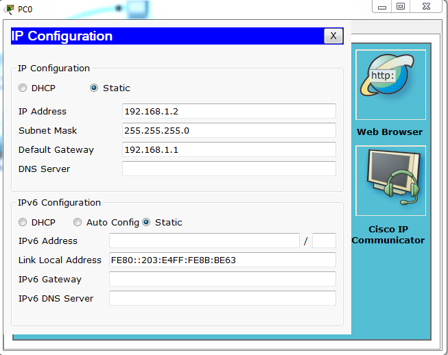
And finally we are done. If you did not understand the above method then check out our video tutorial which is will guide to step by step for assigning the IP Address to the Fasth Ethernet of Cisco Router.
If You still have any queries about assigning the IP address to the CISCO router then please comment below and we will assist you.
Thanks!

int fe0/1
ip address «address» «subnet mask»
ip nat outside
ip access-group «name» in — optional of course I would assume you do have some sort of firewall config
finally, change gateway to the new one.
Was this post helpful?
thumb_up
thumb_down
![]()
Assuming that your router will be plugging directly into your service provider’s router, the information is going to have to match between the two ports (i.e. speed, IP address, duplex, etc.) You will also want to disable CDP on the port. Here is a sample config, with some info omitted:
interface FastEthernet0/1 description xxxxxxxxxx bandwidth xxxxxxx ip address xxx.xxx.xxx.xxx 255.255.255.252 no ip redirects no ip unreachables no ip proxy-arp speed xxxx duplex xxxx no cdp enable no cdp tlv server-location no cdp tlv app end
Was this post helpful?
thumb_up
thumb_down

don’t forget about «enable» and «conf t» before everything else if you’ll do it from the console/shell.
Also «wr» after you will be happy with your new config.
Was this post helpful?
thumb_up
thumb_down
![]()
Sorry, the cut and paste didn’t keep the formatting:
interface FastEthernet0/1
description xxxxxxxxxx
bandwidth
xxxxxxx
ip address xxx.xxx.xxx.xxx 255.255.255.252
no ip redirects
no
ip unreachables
no ip proxy-arp
speed xxxx
duplex xxxx
no cdp enable
no
cdp tlv server-location
no cdp tlv app
end
Was this post helpful?
thumb_up
thumb_down
![]()
Don’t forget «no shut» too. If you run a «sh ip int br» it should show the status of the port. If both don’t say up, then it won’t work. Also, is the cable plugged in and the device on the other end. Somethings you can’t ping your local interface if the other end isn’t attached. Crazy I know, but I have personally seen it with a 1841 router.
Was this post helpful?
thumb_up
thumb_down
Configurations can get complicated on 2811’s since they’re capable of doing so much. If the T1 was an Internet link you’ll need to re-create the NAT rules as well, which are outside of the Interface configs. ACL’s for inbound connections are applied to the Interface, but configured globally outside of the Interface config…
Your ISP will need to provide an IP address for you to use, netmask, and gateway address. And probably a set of DNS servers. At a minimum you will need to configure:
- an IP, netmask, & default gateway on the Interface.
- a default gateway in your route table
- NAT (overload) rules for Internet access
- ip inspect rules and an inbound ACL if any servers are using this link, and you’re not behind another firewall
Here’s an advanced configuration example for your Interface:
Text
interface GigabitEthernet0/0
 ip address 2xx.1xx.9x.xx 255.255.255.248
 ip access-group ACL_IN in
 no ip redirects
 no ip unreachables
 no ip proxy-arp
 ip flow ingress
 ip flow egress
 ip nat outside
 ip inspect outbound out
 ip virtual-reassembly
 ip route-cache flow
 duplex auto
 speed auto
 standby 6 ip 2xx.1xx.9x.xx
 standby 6 preempt
 no mop enabled
 max-reserved-bandwidth 100
 service-policy output voice
Here’s a configuration example for your inspect rules, default route, inbound ACL to allow website traffic and VPN access to a server, and NAT entries:
Text
!
ip inspect name outbound tcp
ip inspect name outbound udp
ip inspect name outbound ftp
ip inspect name outbound icmp
!
ip route 0.0.0.0 0.0.0.0 2xx.1xx.9x.2x
!
!
ip nat pool Internet 2xx.1xx.1xx.x1 2xx.1xx.1xx.x1 prefix-length 26
!
ip nat inside source list 1 pool Internet overload
!
ip nat inside source static 192.168.1.200 2xx.1xx.1xx.xx
!
access-list 1 permit 192.168.1.0 0.0.0.255
!
!
ip access-list extended ACL_IN
 permit ip 2xx.1xx.9x.xx 0.0.0.7 any
 permit tcp any host 2xx.1xx.1xx.xx eq 1723
 permit gre any host 2xx.1xx.1xx.xx
 permit tcp any host 2xx.1xx.1xx.xx eq www
 permit tcp any host 2xx.1xx.1xx.xx eq 443
 deny   ip  any any log
Hope this helps!
Was this post helpful?
thumb_up
thumb_down

this is the configuration of the t-1 on the same router now which is using the WIC card
show run
Building configuration…
Current configuration : 2733 bytes
!
version 12.4
service timestamps debug uptime
service timestamps log uptime
no service password-encryption
!
hostname BNG-Hatfield-ISP
!
boot-start-marker
boot-end-marker
!
logging buffered 4096 debugging
enable secret 5 $1$dUp3$ykzflUPOnYRvghs.UKsBB.
enable password ****
!
no aaa new-model
!
resource policy
!
mmi polling-interval 60
no mmi auto-configure
—More— no mmi pvc
mmi snmp-timeout 180
ip subnet-zero
ip cef
!
!
no ip dhcp use vrf connected
!
!
no ip domain lookup
!
username admin privilege 15 password 0 *****
username administrator privilege 15 password 0 *****
!
!
!
interface FastEthernet0/0
description connected to Pix firewall
ip address 65.246.25.33 255.255.255.240
no ip route-cache cef
no ip route-cache
no ip mroute-cache
speed 100
—More— full-duplex
!
interface FastEthernet0/1
no ip address
shutdown
duplex auto
speed auto
!
interface Serial0/2/0
description connected to Internet
bandwidth 1544
no ip address
encapsulation frame-relay IETF
service-module t1 timeslots 1-24
frame-relay lmi-type ansi
!
interface Serial0/2/0.500 point-to-point
description Verizon Frame Relay
ip unnumbered FastEthernet0/0
frame-relay interface-dlci 500 IETF
!
ip classless
ip route 0.0.0.0 0.0.0.0 Serial0/2/0.500
—More— !
ip http server
!
!
control-plane
!
banner login ^CC
C
!
line con 0
line aux 0
line vty 0 4
what would be the configuration on the new fast ethernet connection
thanks again for your time and help
Was this post helpful?
thumb_up
thumb_down
was hoping for a complete answer but here you go you get the points
Was this post helpful?
thumb_up
thumb_down