На чтение 7 мин Просмотров 8.4к.

Максим aka WisH
Высшее образование по специальности «Информационные системы». Опыт работы системным администратором — 5 лет.
Задать вопрос
Все привыкли к тому, что в квартиру заходит кабель от провайдера, к которому подключается ваш маршрутизатор или оборудование от самого провайдера. Теперь это не единственный способ произвести подключение вашего дома или офиса к сети. Если в роутере есть режим WISP, то он может поработать приемником беспроводного сигнала, через который произойдет подключение к интернету.
Содержание
- Что за технология WISP
- Когда необходимо использование Wireless ISP
- Режим WISP на различных маршрутизаторах
- Настройка на примере роутера TP-Link
Что за технология WISP
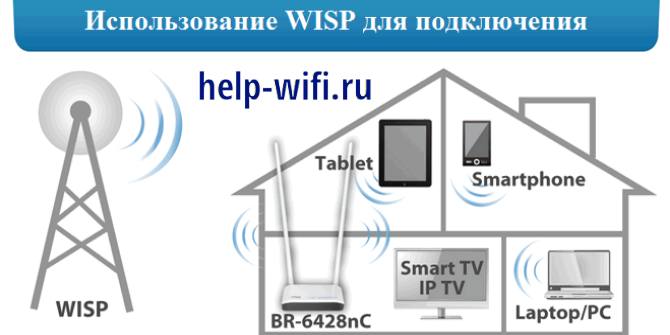
WISP полностью расшифровывается как Wireless Internet Service Provider. Если перевести на русский, то получится что-то вроде поставщика услуг беспроводного интернета. Название полностью описывает всю технологию применения: никакие кабеля в квартиру к вам не заходят, провайдер дает доступ к своей беспроводной сети, к которой пользователь подключает свой роутер и с него уже пользуется интернетом.
Для пользователя Wi-Fi сети отличий одного способа подключения от другого не так уж и много. Нужно иметь на своем маршрутизаторе режим для подключения к такой сети и все. Фактически, роутер пользователя будет работать в качестве повторителя, ретранслируя основной сигнал от провайдера. Внутреннюю сетку организовать стоит, потому что так безопаснее и перехватить сигналы от каждого вида оборудования будет сложнее.
Для пользователя нет отличий в сложности настройки подключения, так что выбирайте по цене и качеству связи.
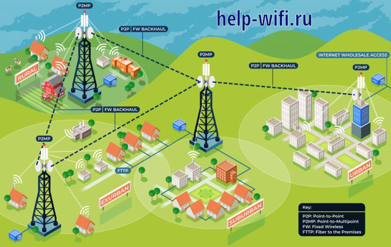
Со стороны провайдера все организовано несколько сложнее. Где-то в регионе или городе есть центральная точка, которая соединяется с магистральным интернетом по проводу. На крыше здания установлены антенны и оборудование для передачи сигнала. На краях этой первой зоны покрытия установлено еще оборудование, работающие в качестве ретрансляторов и подключенное к основному по принципу беспроводного моста.
Так эти ретрансляторы добираются до дома клиента. В самом доме, или в одном из ближайших, также установлена мощная точка доступа, которая раздает сеть всем клиентам. В целом, вся организация сети похожа на мобильные сети. Отличие в том, что здесь вы можете подключиться только к своему конечному оборудованию, а все остальные ретрансляторы в городе для вас останутся недоступны.
Когда необходимо использование Wireless ISP
От вас не зависит возможность подключения Wireless ISP. Если провайдер провел к вам в город и в ваш район беспроводную сеть, то шансы на подключение есть, если же не проводил, то и подключиться никак не получится. Если в городе уже давно есть интернет, то там сформировалась своя архитектура сети и, скорее всего, проложены кабеля, которые проработают еще очень долго. В таких случаях невыгодно менять рабочие кабеля на другую систему.
Такой способ подключения используется в тех местах, где кабеля еще не проложены или прокладывать их очень сложно. Например, при подключении удаленных районов с малым количеством абонентов. По правилам пришлось бы тянуть провода и устанавливать конечное оборудование в каждой деревне, что не окупится долго. Одна же вышка с технологией WISP, при удаче, способна охватить несколько деревень.
Такой способ используется и в других местах с трудным доступом. Иногда проще установить антенны и оборудование на крышах, чем пытаться протянуть километры проводов через застроенные районы.
Несмотря на удобство подключения, расплачиваться за это придется уменьшением скорости и увеличением времени загрузки интернет-ресурсов.
Подключение через беспроводную сеть имеет минусы для обеих сторон. Для клиента – это будет снижение скорости сети и повышение времени отклика интернет ресурсов. Для провайдера – это большая цена оборудование и необходимость проводить профилактику и ремонт чаще. Частое обслуживание требуется из-за более активной работы оборудования, которое отправляет и принимает сигналы постоянно.
Режим WISP на различных маршрутизаторах
Большая часть маршрутизаторов поддерживает подключение через беспроводную сеть. Такая возможность есть у Zyxel Keenetic и многих моделей MikroTik. Остальные современные роутеры также подойдут для подключения, но лучше уточните этот момент в характеристиках своей модели. Если она куплена давно, то на ней может и не оказаться поддержки WISP.
В целом, настройка для разных моделей и производителей отличается, хотя и не сильно. Если вы уже настраивали свой роутер для работы через провод, то знаете, где находятся нужные параметры. Остается подключить беспроводной сигнал от провайдера, вместо провода из WAN-порта. В случае возникновения трудностей, найдите инструкцию конкретно для вашей модели роутера.
Настройка на примере роутера TP-Link
Разберем настройку на примере роутеров TP-Link. В среднем, похожим образом будут настраиваться и другие маршрутизаторы. Если настраивали самостоятельно и помните алгоритм действий, то поищите похожие названия в пунктах меню своего устройства.
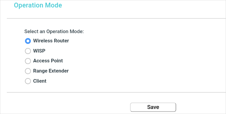
Сначала зайдите в браузер и введите в адресной строке tplinklogin.net. В открывшемся окне впишите логин и пароль, стандартный admin/admin, если меняли, то впишите свой. В левом меню выберите «Operation Mode», а потом «Wireless Client Router». Сохраните настройки.

Теперь переходите в раздел Wireless, пункт Wireless Settings. В правой части окна нажмите на “Survey” и выберите сеть, к которой хотите подключиться. В нижней части этого же окна настройте название своей сети, как оно будет отображаться дома. Остальные настройки оставьте прежними.
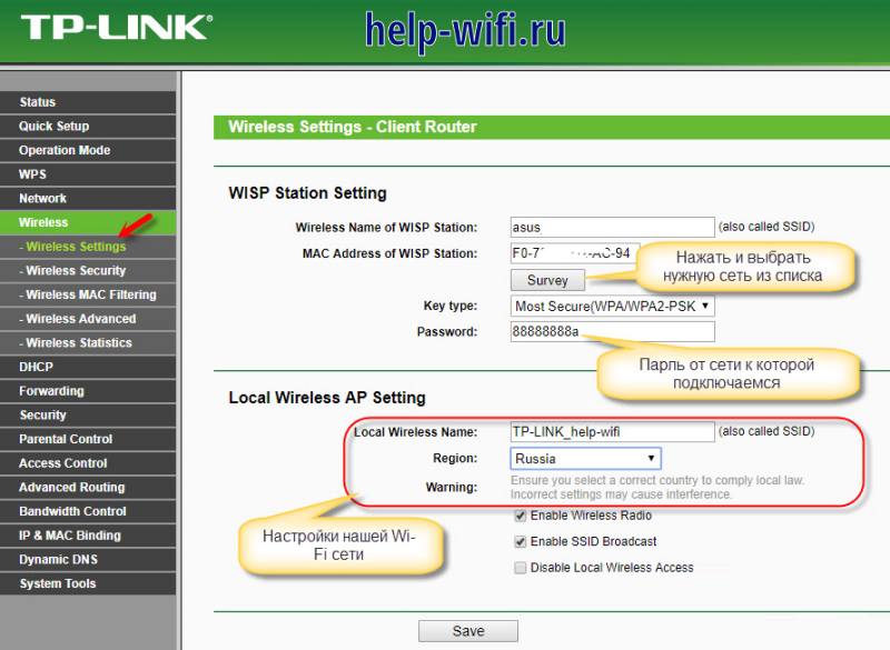
В старых станциях был отдельный пункт для настроек, как это показано в нашей инструкции. В новых такого нет, достаточно, чтобы ваш маршрутизатор умел работать в режиме беспроводного моста. Нужно переключить его в этот режим, иногда получится это сделать из расширенных настроек, а иногда полностью сбрасываются все настройки до заводских, чтобы переключить в нужный режим работы.
В режиме моста нужно найти сеть, к которой хотите подключиться, ввести от неё данные и потом задать имя и пароль от собственной сети. Второе имя и пароль будут отображаться у вас в квартире, к ним и будет происходить подключение оборудования.
Если у вас роутер бренда Netis, то посмотрите видео-инструкцию по настройке WISP-режима:
WISP позволяет получить интернет там, куда провода тянуть дорого и долго. Это увеличивает цену на услуги из-за повышенного износа оборудования, а также уменьшает скорость и стабильность, по сравнению с проводным соединением. Клиенту стоит купить мощной роутер, чтобы он мог одновременно обмениваться данными с сетью провайдера и поддерживать адекватную скорость внутри домашней сети.
Предоставление беспроводных услуг провайдером поможет дотянуть приличный интернет до самых удаленных регионов, что перекрывает его недостатки. По мере развития связи и беспроводных технологий они могут перейти в плюсы и все вообще откажутся от проводной связи.
Chapter 4 Configure the Router in Wireless Router Mode
This chapter presents how to configure the various features of the router working as a standard wireless router.
It contains the following sections:
•Status
•Operation Mode
•Network
•Wireless
•Guest Network
•DHCP
•Forwarding
•Security
•Parental Controls
•Access Control
•Advanced Routing
•Bandwidth Control
•IP & MAC Binding
•Dynamic DNS
•IPv6
•System Tools
•Log out
1. Status
1.Visit http://tplinkwifi.net, and log in with the username and password you set for the router.
2.Go to Status. You can view the current status information of the router.
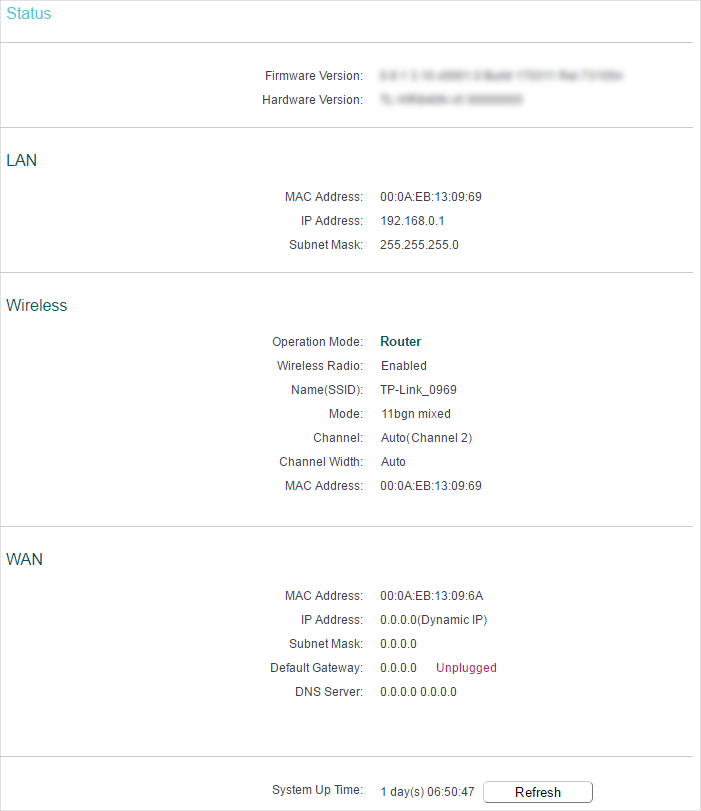
•Firmware Version — The version information of the router’s firmware.
•Hardware Version — The version information of the router’s hardware.
•LAN — This field displays the current settings of the LAN, and you can configure them on the Network > LAN page.
•MAC address — The physical address of the router.
•IP address — The LAN IP address of the router.
•Subnet Mask — The subnet mask associated with the LAN IP address.
•Wireless — This field displays the basic information or status of the wireless function, and you can configure them on the Wireless > Basic Settings page.
•Operation Mode — The current wireless working mode in use.
•Wireless Radio — Indicates whether the wireless radio feature of the router is enabled or disabled.
•Name(SSID) — The SSID of the router.
•Mode — The current wireless mode which the router works on.
•Channel — The current wireless channel in use.
•Channel Width — The current wireless channel width in use.
•MAC Address — The physical address of the router.
•WAN — This field displays the current settings of the WAN, and you can configure them on the Network > WAN page.
•MAC Address — The physical address of the WAN port.
•IP Address — The current WAN (Internet) IP Address. This field will be blank or 0.0.0.0 if the IP Address is assigned dynamically and there is no internet connection.
•Subnet Mask — The subnet mask associated with the WAN IP Address.
•Default Gateway — The Gateway currently used is shown here. When you use Dynamic IP as the internet connection type, click Renew or Release here to obtain new IP parameters dynamically from the ISP or release them.
•DNS Server — The IP addresses of DNS (Domain Name System) server.
•System Up Time — The length of the time since the router was last powered on or reset.
Click Refresh to get the latest status and settings of the router.
2. Operation Mode
1.Visit http://tplinkwifi.net, and log in with the username and password you set for the router.
2.Go to Operation Mode.
3.Select the working mode as needed and click Save.
3. Network
3.1. WAN
1.Visit http://tplinkwifi.net, and log in with the username and password you set for the router.
2.Go to Network > WAN.
3.Configure the IP parameters of the WAN and click Save.
Dynamic IP
If your ISP provides the DHCP service, please select Dynamic IP, and the router will automatically get IP parameters from your ISP.
Click Renew to renew the IP parameters from your ISP.
Click Release to release the IP parameters.
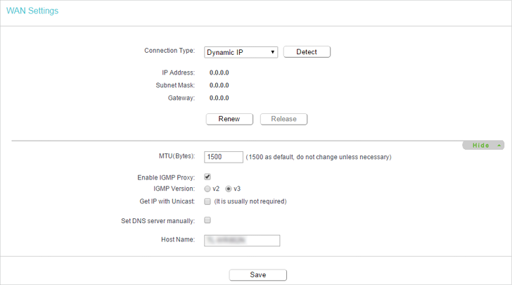
•MTU(Bytes) — The normal MTU (Maximum Transmission Unit) value for most Ethernet networks is 1500 Bytes. It is not recommended that you change the default MTU size unless required by your ISP.
•Enable IGMP Proxy — IGMP (Internet Group Management Protocol) is used to manage multicasting on TCP/IP networks. Some ISPs use IGMP to perform remote configuration for client devices, such as the modem router. The default value is enabled, and if you are not sure, please contact your ISP or just leave it.
•Get IP with Unicast — A few ISPs’ DHCP servers do not support the broadcast applications. If you cannot get the IP address normally, you can choose this option. (It is rarely required.)
•Set DNS server manually — If your ISP gives you one or two DNS addresses, select Set DNS server manually and enter the primary and secondary addresses into the correct fields. Otherwise, the DNS servers will be assigned automatically from your ISP.
•Host Name -This option specifies the name of the router.
Static IP
If your ISP provides a static or fixed IP address, subnet mask, default gateway and DNS setting, please select Static IP.
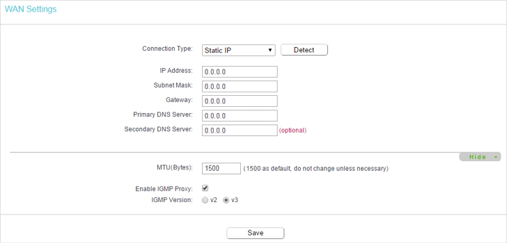
•IP Address — Enter the IP address in dotted-decimal notation provided by your ISP.
•Subnet Mask — Enter the subnet mask in dotted-decimal notation provided by your ISP. Normally 255.255.255.0 is used as the subnet mask.
•Gateway — Enter the gateway IP address in dotted-decimal notation provided by your ISP.
•Primary/Secondary DNS Server — (Optional) Enter one or two DNS addresses in dotted-decimal notation provided by your ISP.
•MTU (Bytes) — The normal MTU (Maximum Transmission Unit) value for most Ethernet networks is 1500 Bytes. It is not recommended that you change the default MTU size unless required by your ISP.
•Enable IGMP Proxy — IGMP (Internet Group Management Protocol) is used to manage multicasting on TCP/IP networks. Some ISPs use IGMP to perform remote configuration for client devices, such as the modem router. The default value is enabled, and if you are not sure, please contact your ISP or just leave it.
PPPoE
If your ISP provides PPPoE connection, select PPPoE.
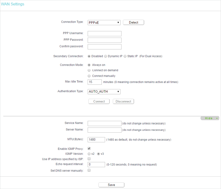
•PPP Username/Password — Enter the user name and password provided by your ISP. These fields are case-sensitive.
•Confirm Password — Enter the Password provided by your ISP again to ensure the password you entered is correct.
•Secondary Connection — It’s available only for PPPoE connection. If your ISP provides an extra connection type, select Dynamic IP or Static IP to activate the secondary connection.
•Connection Mode
•Always On — In this mode, the internet connection will be active all the time.
•Connect on Demand — In this mode, the internet connection can be terminated automatically after a specified inactivity period (Max Idle Time) and be re-established when you attempt to access the internet again. If you want to keep your internet connection active all the time, please enter 0 in the Max Idle Time field. Otherwise, enter the number of minutes you want to have elapsed before your internet access disconnects.
•Connect Manually — You can click Connect/Disconnect to connect/disconnect immediately. This mode also supports the Max Idle Time function as Connect on Demand mode. The internet connection can be disconnected automatically after a specified inactivity period (Max Idle Time) and not be able to re-establish when you attempt to access the internet again.
•Authentication Type — Choose an authentication type.
Note:
Sometimes the connection cannot be terminated although you have specified the Max Idle Time because some applications are visiting the internet continually in the background.
•Service Name/Server Name — The service name and server name should not be configured unless you are sure it is necessary for your ISP. In most cases, leaving these fields blank will work.
•MTU(Bytes) — The default MTU size is 1480 bytes. It is not recommended that you change the default MTU size unless required by your ISP.
•Enable IGMP Proxy — IGMP (Internet Group Management Protocol) is used to manage multicasting on TCP/IP networks. Some ISPs use IGMP to perform remote configuration for client devices, such as the modem router. The default value is enabled, and if you are not sure, please contact your ISP or just leave it.
•ISP Specified IP Address — If your ISP does not automatically assign IP addresses to the router, please select Use IP address specified by ISP and enter the IP address provided by your ISP in dotted-decimal notation.
•Echo Request Interval — The router will detect Access Concentrator online at every interval. The default value is 0. You can input the value between 0 and 120. The value 0 means no detect.
•DNS Server/Secondary DNS Server — If your ISP does not automatically assign DNS addresses to the router, please select Set DNS server manually and enter the IP address in dotted-decimal notation of your ISP’s primary DNS server. If a secondary DNS server address is available, enter it as well.
L2TP
If your ISP provides L2TP connection, please select L2TP.
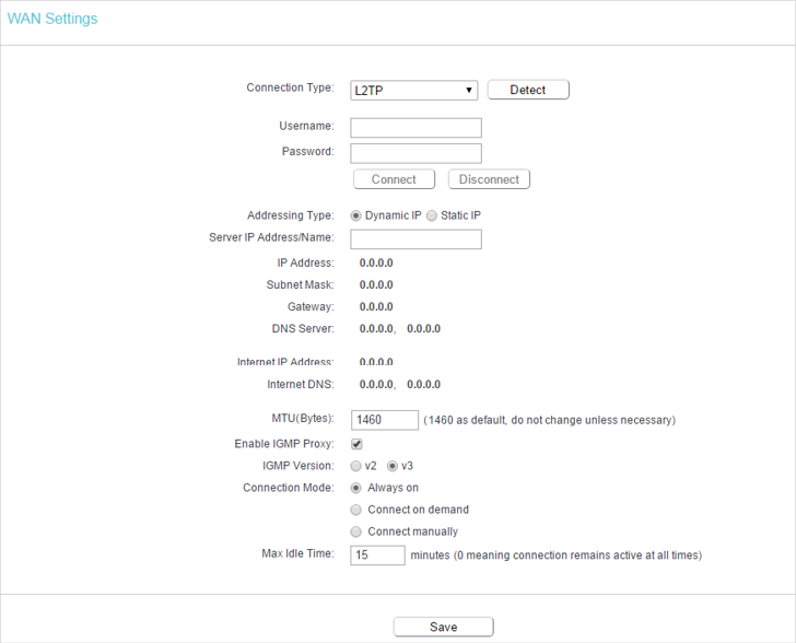
•Username/Password — Enter the username and password provided by your ISP. These fields are case-sensitive.
•Addressing Type — Choose the addressing type given by your ISP, either Dynamic IP or Static IP. Click the Connect button to connect immediately. Click the Disconnect button to disconnect immediately.
•MTU(Bytes) — The default MTU size is “1460” bytes, which is usually fine. It is not recommended that you change the default MTU Size unless required by your ISP.
•Enable IGMP Proxy — IGMP (Internet Group Management Protocol) is used to manage multicasting on TCP/IP networks. Some ISPs use IGMP to perform remote configuration for client devices, such as the modem router. The default value is enabled, and if you are not sure, please contact your ISP or just leave it.
•Connection Mode
•Always On — In this mode, the internet connection will be active all the time.
•Connect on Demand — In this mode, the internet connection can be terminated automatically after a specified inactivity period (Max Idle Time) and be re-established when you attempt to access the internet again. If you want to keep your internet connection active all the time, please enter 0 in the Max Idle Time field. Otherwise, enter the number of minutes you want to have elapsed before your internet access disconnects.
•Connect Manually — You can click Connect/Disconnect to connect/disconnect immediately. This mode also supports the Max Idle Time function as Connect on Demand mode. The internet connection can be disconnected automatically after a specified inactivity period (Max Idle Time) and not be able to re-establish when you attempt to access the internet again.
Note:
Sometimes the connection cannot be terminated although you have specified the Max Idle Time because some applications are visiting the internet continually in the background.
PPTP
If your ISP provides PPTP connection, please select PPTP.
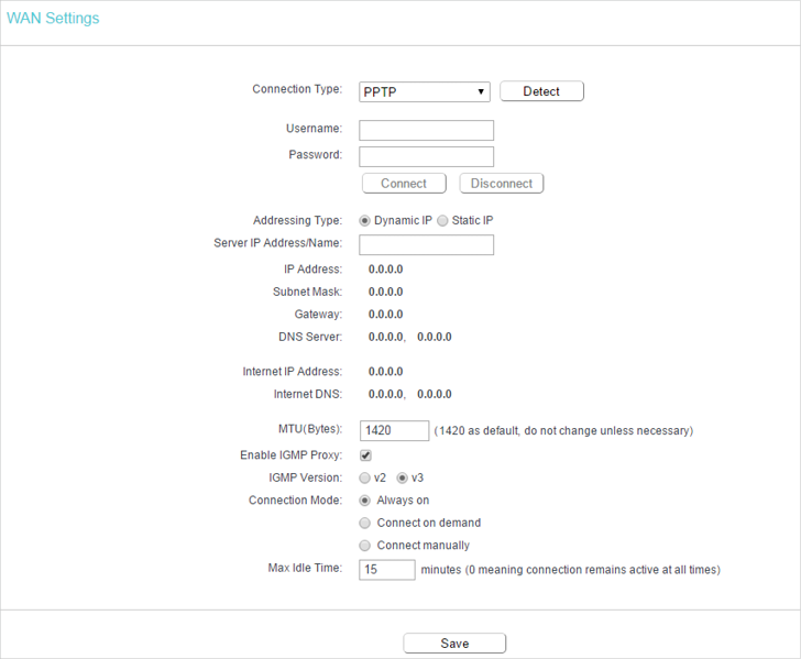
•Username/Password — Enter the username and password provided by your ISP. These fields are case-sensitive.
•Addressing Type — Choose the addressing type given by your ISP, either Dynamic IP or Static IP. Click the Connect button to connect immediately. Click the Disconnect button to disconnect immediately.
•MTU(Bytes) — The default MTU size is “1420” bytes, which is usually fine. It is not recommended that you change the default MTU Size unless required by your ISP.
•Enable IGMP Proxy — IGMP (Internet Group Management Protocol) is used to manage multicasting on TCP/IP networks. Some ISPs use IGMP to perform remote configuration for client devices, such as the modem router. The default value is enabled, and if you are not sure, please contact your ISP or just leave it.
•Connection Mode
•Always On — In this mode, the internet connection will be active all the time.
•Connect on Demand — In this mode, the internet connection can be terminated automatically after a specified inactivity period (Max Idle Time) and be re-established when you attempt to access the internet again. If you want to keep your internet connection active all the time, please enter 0 in the Max Idle Time field. Otherwise, enter the number of minutes you want to have elapsed before your internet access disconnects.
•Connect Manually — You can click Connect/Disconnect to connect/disconnect immediately. This mode also supports the Max Idle Time function as Connect on Demand mode. The internet connection can be disconnected automatically after a specified inactivity period (Max Idle Time) and not be able to re-establish when you attempt to access the internet again.
Note:
Sometimes the connection cannot be terminated although you have specified the Max Idle Time because some applications are visiting the internet continually in the background.
BigPond Cable
If your ISP provides BigPond cable connection, please select BigPond Cable.
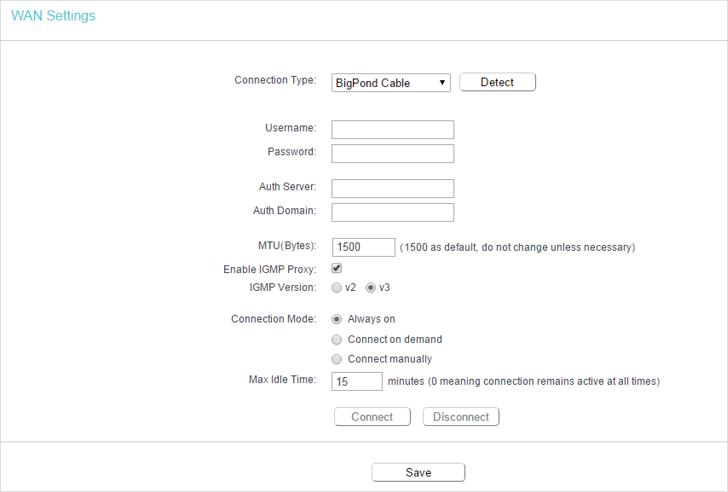
•Username/Password — Enter the username and password provided by your ISP. These fields are case-sensitive.
•Auth Server — Enter the authenticating server IP address or host name.
•Auth Domain — Type in the domain suffix server name based on your location.
•MTU(Bytes) — The default MTU size is 1500 bytes. It is not recommended that you change the default MTU size unless required by your ISP.
•Enable IGMP Proxy — IGMP (Internet Group Management Protocol) is used to manage multicasting on TCP/IP networks. Some ISPs use IGMP to perform remote configuration for client devices, such as the modem router. The default value is enabled, and if you are not sure, please contact your ISP or just leave it.
•Connection Mode
•Always On — In this mode, the internet connection will be active all the time.
•Connect on Demand — In this mode, the internet connection can be terminated automatically after a specified inactivity period (Max Idle Time) and be re-established when you attempt to access the internet again. If you want to keep your internet connection active all the time, please enter 0 in the Max Idle Time field. Otherwise, enter the number of minutes you want to have elapsed before your internet access disconnects.
•Connect Manually — You can click Connect/Disconnect to connect/disconnect immediately. This mode also supports the Max Idle Time function as Connect on Demand mode. The internet connection can be disconnected automatically after a specified inactivity period (Max Idle Time) and not be able to re-establish when you attempt to access the internet again.
3.2. LAN
1.Visit http://tplinkwifi.net, and log in with the username and password you set for the router.
2.Go to Network > LAN.
3.Configure the IP parameters of the LAN and click Save.
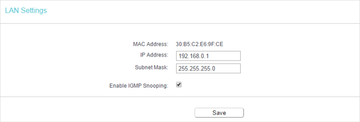
•MAC Address — The physical address of the LAN ports. The value can not be changed.
•IP Address — Enter the IP address in dotted-decimal notation of your router (the default one is 192.168.0.1).
•Subnet Mask — An address code that determines the size of the network. Normally 255.255.255.0 is used as the subnet mask.
•Enable IGMP Snooping — IGMP snooping is designed to prevent hosts on a local network from receiving traffic for a multicast group they have not explicitly joined. IGMP snooping is especially useful for bandwidth-intensive IP multicast applications such as IPTV.
Note:
•If you have changed the IP address, you must use the new IP address to log in.
•If the new IP address you set is not in the same subnet as the old one, the IP address pool in the DHCP Server will be configured automatically, but the Virtual Server and DMZ Host will not take effect until they are re-configured.
3.3. MAC Clone
1.Visit http://tplinkwifi.net, and log in with the username and password you set for the router.
2.Go to Network > MAC Clone.
3.Configure the WAN MAC address and click Save.
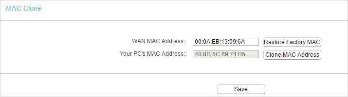
•WAN MAC Address — This field displays the current MAC address of the WAN port. If your ISP requires you to register the MAC address, please enter the correct MAC address in this field. Click Restore Factory MAC to restore the MAC address of WAN port to the factory default value.
•Your PC’s MAC Address — This field displays the MAC address of the PC that is managing the router. If the MAC address is required, you can click Clone MAC Address and this MAC address will be filled in the WAN MAC Address field.
Note:
•You can only use the MAC Address Clone function for PCs on the LAN.
•If you have changed the WAN MAC address when the WAN connection is PPPoE, it will not take effect until the connection is re-established.
4. Wireless
4.1. Basic Settings
1.Visit http://tplinkwifi.net, and log in with the username and password you set for the router.
2.Go to Wireless > Basic Settings.
3.Configure the basic settings for the wireless network and click Save.
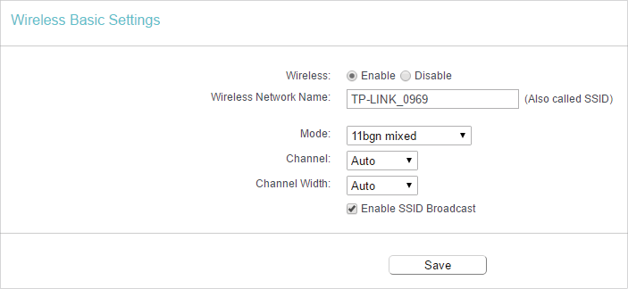
•Wireless — Enable or disable wireless network.
•Wireless Network Name — Enter a value of up to 32 characters. The same Name (SSID) must be assigned to all wireless devices in your network.
•Mode — You can choose the appropriate “Mixed” mode.
•Channel — This field determines which operating frequency will be used. The default channel is set to Auto. It is not necessary to change the wireless channel unless you notice interference problems with another nearby access point.
•Channel Width — This field determines which operating frequency will be used. It is not necessary to change the wireless channel unless you notice interference problems with another nearby access point. If you select auto, then AP will choose the best channel automatically.
•Enable SSID Broadcast — If enabled, the router will broadcast the wireless network name (SSID).
4.2. WPS
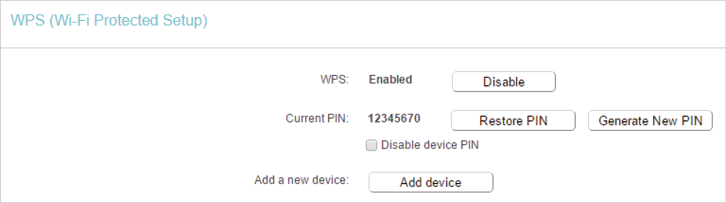
WPS (Wi-Fi Protected Setup) can help you to quickly and securely connect to a network. This section will guide you to add a new wireless device to your router’s network quickly via WPS.
Note:
The WPS function cannot be configured if the wireless function of the router is disabled. Please make sure the wireless function is enabled before configuration.
1.Visit http://tplinkwifi.net, and log in with the username and password you set for the router.
2.Go to Wireless > WPS.
3.Follow one of the following three methods to connect your client device to the router’s Wi-Fi network.
Method ONE: Press the WPS Button on Your Client Device
1.Keep the WPS Status as Enabled and click Add Device.
2.Select Press the WPS button of the new device within the next two minutes and click Connect.
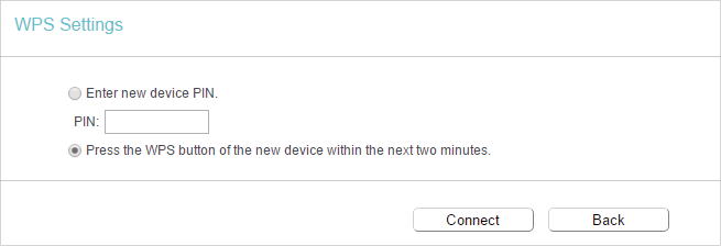
3.Within two minutes, press the WPS button on your client device.
4.A success message will appear on the WPS page if the client device has been successfully added to the router’s network.
Method TWO: Enter the Client’s PIN
1.Keep the WPS Status as Enabled and click Add Device.
2.Select Enter new device PIN, enter your client device’s current PIN in the PIN filed and click Connect.
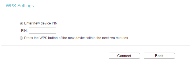
3.A success message will appear on the WPS page if the client device has been successfully added to the router’s network.
Method Three: Enter the Router’s PIN
1.Keep the WPS Status as Enabled and get the Current PIN of the router.
2.Enter the router’s current PIN on your client device to join the router’s Wi-Fi network.
4.3. Wireless Security
1.Visit http://tplinkwifi.net, and log in with the username and password you set for the router.
2.Go to Wireless > Wireless Security.
3.Configure the security settings of your wireless network and click Save.
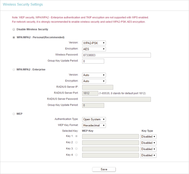
•Disable Wireless Security — The wireless security function can be enabled or disabled. If disabled, wireless clients can connect to the router without a password. It’s strongly recommended to choose one of the following modes to enable security.
•WPA-PSK/WPA2-Personal — It’s the WPA/WPA2 authentication type based on pre-shared passphrase.
•Version — Select Auto, WPA-PSK or WPA2-PSK.
•Encryption — Select Auto, TKIP or AES.
•Wireless Password — Enter ASCII or Hexadecimal characters. For Hexadecimal, the length should be between 8 and 64 characters; for ASCII, the length should be between 8 and 63 characters.
•Group Key Update Period — Specify the group key update interval in seconds. The value can be 0 or at least 30. Enter 0 to disable the update.
•WPA /WPA2-Enterprise — It’s based on Radius Server.
•Version — Select Auto, WPA or WPA2.
•Encryption — Select Auto, TKIP or AES.
•RADIUS Server IP — Enter the IP address of the Radius server.
•RADIUS Server Port — Enter the port that Radius server used.
•RADIUS Server Password — Enter the password for the Radius server.
•Group Key Update Period — Specify the group key update interval in seconds. The value should be 30 or above. Enter 0 to disable the update.
•WEP — It is based on the IEEE 802.11 standard.
•Authentication Type — The default setting is Auto, which can select Shared Key or Open System authentication type automatically based on the wireless client’s capability and request.
•WEP Key Format — Hexadecimal and ASCII formats are provided here. Hexadecimal format stands for any combination of hexadecimal digits (0-9, a-f, A-F) in the specified length. ASCII format stands for any combination of keyboard characters in the specified length.
•WEP Key — Select which of the four keys will be used and enter the matching WEP key. Make sure these values are identical on all wireless clients in your network.
•Key Type — Select the WEP key length (64-bit, 128-bit or 152-bit) for encryption. Disabled means this WEP key entry is invalid.
•64-bit — Enter 10 hexadecimal digits (any combination of 0-9, a-f and A-F. Null key is not permitted) or 5 ASCII characters.
•128-bit — Enter 26 hexadecimal digits (any combination of 0-9, a-f and A-F. Null key is not permitted) or 13 ASCII characters.
4.4. Wireless MAC Filtering
Wireless MAC Filtering is used to deny or allow specific wireless client devices to access your network by their MAC addresses.
I want to:
Deny or allow specific wireless client devices to access my network by their MAC addresses.
For example, you want the wireless client A with the MAC address 00:0A:EB:B0:00:0B and the wireless client B with the MAC address 00:0A:EB:00:07:5F to access the router, but other wireless clients cannot access the router
How can I do that?
1.Visit http://tplinkwifi.net, and log in with the username and password you set for the router.
2.Go to Wireless > Wireless MAC Filtering.
3.Click Enable to enable the Wireless MAC Filtering function.
4.Select Allow the stations specified by any enabled entries in the list to access as the filtering rule.
5.Delete all or disable all entries if there are any entries already.
6.Click Add New and fill in the blank.
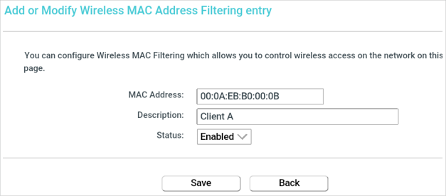
1 )Enter the MAC address 00:0A:EB:B0:00:0B / 00:0A:EB:00:07:5F in the MAC Address field.
2 )Enter wireless client A/B in the Description field.
3 )Select Enabled in the Status drop-down list.
4 )Click Save and click Back.
7.The configured filtering rules should be listed as the picture shows below.
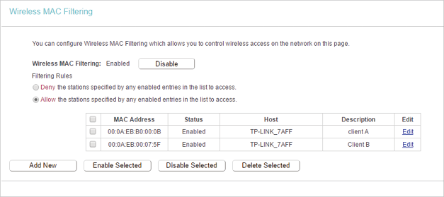
Done!
Now only client A and client B can access your network.
4.5. Wireless Advanced
1.Visit http://tplinkwifi.net, and log in with the username and password you set for the router.
2.Go to Wireless > Wireless Advanced.
3.Configure the advanced settings of your wireless network and click Save.
Note:
If you are not familiar with the setting items on this page, it’s strongly recommended to keep the provided default values; otherwise it may result in lower wireless network performance.
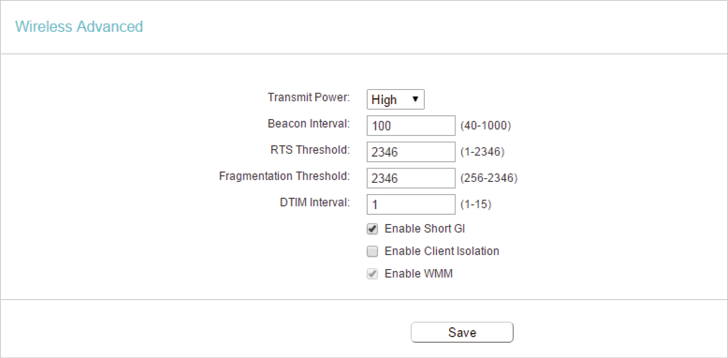
•Transmit Power — Select High, Middle or Low which you would like to specify for the router. High is the default setting and recommended.
•Beacon Interval — Enter a value between 40-1000 milliseconds for Beacon Interval here. Beacon Interval value determines the time interval of the beacons. The beacons are the packets sent by the router to synchronize a wireless network. The default value is 100.
•RTS Threshold — Here you can specify the RTS (Request to Send) Threshold. If the packet is larger than the specified RTS Threshold size, the router will send RTS frames to a particular receiving station and negotiate the sending of a data frame. The default value is 2346.
•Fragmentation Threshold — This value is the maximum size determining whether packets will be fragmented. Setting a low value for the Fragmentation Threshold may result in poor network performance because of excessive packets. 2346 is the default setting and is recommended.
•DTIM Interval — This value determines the interval of the Delivery Traffic Indication Message (DTIM). A DTIM field is a countdown field informing clients of the next window for listening to broadcast and multicast messages. When the router has buffered broadcast or multicast messages for associated clients, it sends the next DTIM with a DTIM Interval value. You can specify the value between 1-255 Beacon Intervals. The default value is 1, which indicates the DTIM Interval is the same as Beacon Interval.
•Enable Short GI — It is recommended to enable this function, for it will increase the data capacity by reducing the guard interval time.
•Enable Client Isolation — This function isolates all connected wireless stations so that wireless stations cannot access each other through WLAN. This function will be disabled if WDS/Bridge is enabled.
•Enable WMM — WMM function can guarantee the packets with high-priority messages being transmitted preferentially. It is strongly recommended to enable this function.
4.6. Wireless Statistics
1.Visit http://tplinkwifi.net, and log in with the username and password you set for the router.
2.Go to Wireless > Wireless Statistics to check the data packets sent and received by each client device connected to the router.
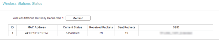
•MAC Address — The MAC address of the connected wireless client.
•Current Status — The running status of the connected wireless client.
•Received Packets — Packets received by the wireless client.
•Sent Packets — Packets sent by the wireless client.
•SSID — SSID that the station associates with.
5. Guest Network
Guest Network allows you to provide Wi-Fi access for guests without disclosing your host network. When you have guests in your house, apartment, or workplace, you can create a guest network for them. In addition, you can customize guest network settings to ensure network security and privacy.
1.Visit http://tplinkwifi.net, and log in with the username and password you set for the router.
2.Go to Guest Network.
3.Enable the Guset Network function.
4.Create a network name for your guest network.
5.Select the Security type and create the Password of the guest network.
6.Select Schedule from the Access Time drop-down list and customize it for the guest network.
7.Click Save.
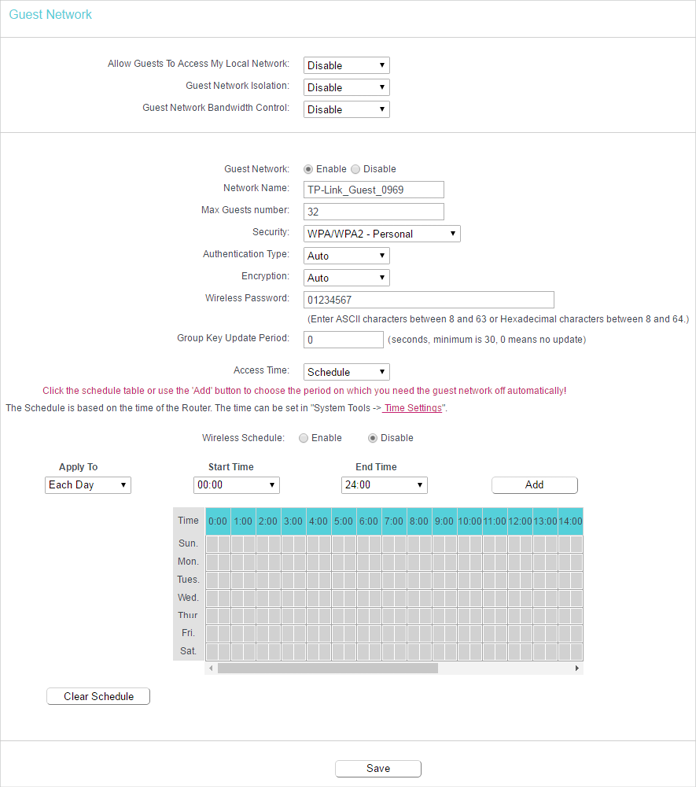
•Allow Guest To Access My Local Network — If enabled, guests can access the local network and manage it.
•Guest Network Isolation — If enabled, guests are isolated from each other.
•Enable Guest Network Bandwidth Control — If enabled, the Guest Network Bandwidth Control rules will take effect.
Note:
The range of bandwidth for guest network is calculated according to the setting of Bandwidth Control on the Bandwidth Control page.
6. DHCP
By default, the DHCP (Dynamic Host Configuration Protocol) Server is enabled and the router acts as a DHCP server; it dynamically assigns TCP/IP parameters to client devices from the IP Address Pool. You can change the settings of DHCP Server if necessary, and you can reserve LAN IP addresses for specified client devices.
6.1. DHCP Settings
1.Visit http://tplinkwifi.net, and log in with the username and password you set for the router.
2.Go to DHCP > DHCP Settings.
3.Specify DHCP server settings and click Save.
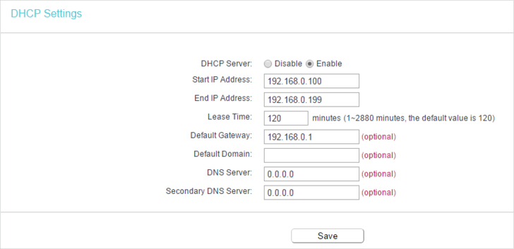
•DHCP Server — Enable or disable the DHCP server. If disabled, you must have another DHCP server within your network or else you must configure the computer manually.
•Start IP Address — Specify an IP address for the DHCP Server to start with when assigning IP addresses. 192.168.0.100 is the default start address.
•End IP Address — Specify an IP address for the DHCP Server to end with when assigning IP addresses. 192.168.0.199 is the default end address.
•Address Lease Time — The Address Lease Time is the amount of time a network user will be allowed to connect to the router with the current dynamic IP Address. When time is up, the user will be automatically assigned a new dynamic IP address. The range of the time is 1 ~ 2880 minutes. The default value is 120.
•Default Gateway (Optional) — It is suggested to input the IP address of the LAN port of the router. The default value is 192.168.0.1.
•Default Domain (Optional) — Input the domain name of your network.
•DNS Server (Optional) — Input the DNS IP address provided by your ISP.
•Secondary DNS Server (Optional) — Input the IP address of another DNS server if your ISP provides two DNS servers.
Note:
To use the DHCP server function of the router, you must configure all computers on the LAN as Obtain an IP Address automatically.
6.2. DHCP Clients List
1.Visit http://tplinkwifi.net, and log in with the username and password you set for the router.
2.Go to DHCP > DHCP Clients List to view the information of the clients connected to the router.
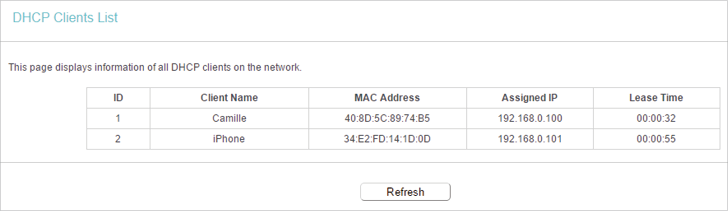
•Client Name — The name of the DHCP client.
•MAC Address — The MAC address of the DHCP client.
•Assigned IP — The IP address that the outer has allocated to the DHCP client.
•Lease Time — The time of the DHCP client leased. After the dynamic IP address has expired, a new dynamic IP address will be automatically assigned to the user.
You cannot change any of the values on this page. To update this page and show the current attached devices, click Refresh.
6.3. Address Reservation
You can reserve an IP address for a specific client. When you specify a reserved IP address for a PC on the LAN, this PC will always receive the same IP address each time when it accesses the DHCP server.
1.Visit http://tplinkwifi.net, and log in with the username and password you set for the router.
2.Go to DHCP > Address Reservation.
3.Click Add New and fill in the blanks.
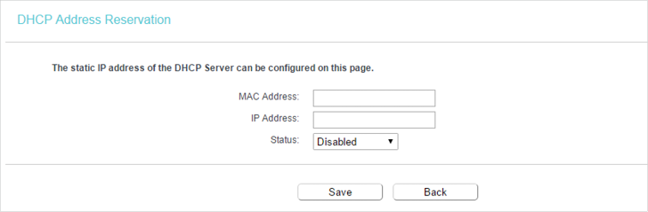
1 )Enter the MAC address (in XX:XX:XX:XX:XX:XX format.) of the client for which you want to reserve an IP address.
2 )Enter the IP address (in dotted-decimal notation) which you want to reserve for the client.
3 )Leave the Status as Enabled.
4 )Click Save.
7. Forwarding
The router’s NAT (Network Address Translation) feature makes the devices on the LAN use the same public IP address to communicate on the internet, which protects the local network by hiding IP addresses of the devices. However, it also brings about the problem that external hosts cannot initiatively communicate with the specified devices in the local network.
With the forwarding feature, the router can traverse the isolation of NAT so that clients on the internet can reach devices on the LAN and realize some specific functions.
The TP-Link router includes four forwarding rules. If two or more rules are set, the priority of implementation from high to low is Virtual Servers, Port Triggering, UPNP and DMZ.
7.1. Virtual Server
When you build up a server in the local network and want to share it on the internet, Virtual Servers can realize the service and provide it to internet users. At the same time virtual servers can keep the local network safe as other services are still invisible from the internet.
Virtual Servers can be used to set up public services in your local network, such as HTTP, FTP, DNS, POP3/SMTP and Telnet. Different service uses different service port. Port 80 is used in HTTP service, port 21 in FTP service, port 25 in SMTP service and port 110 in POP3 service. Please verify the service port number before the configuration.
I want to:
Share my personal website I’ve built in local network with my friends through the internet.
For example, the personal website has been built in my home PC (192.168.0.100). I hope that my friends on the internet can visit my website in some way. My PC is connected to the router with the WAN IP address 218.18.232.154.
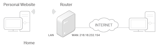
1.Set your PC to a static IP address, for example 192.168.0.100.
2.Visit http://tplinkwifi.net, and log in with the username and password you set for the router.
3.Go to Forwarding > Virtual Server.
4.Click Add New. Select HTTP from the Common Service Port list. The service port, internal port and protocol will be automatically filled in. Enter the PC’s IP address 192.168.0.100 in the IP Address field.
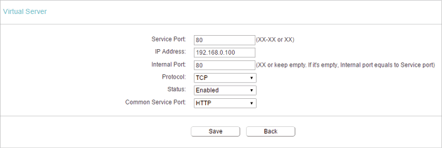
5.Leave the status as Enabled and click Save.
Note:
•It is recommended to keep the default settings of Internal Port and Protocol if you are not clear about which port and protocol to use.
•If the service you want to use is not in the Common Service Port list, you can enter the corresponding parameters manually. You should verify the port number that the service needs.
•You can add multiple virtual server rules if you want to provide several services in a router. Please note that the Service Port should not be overlapped.
Done!
Users on the internet can enter http:// WAN IP (in this example: http:// 218.18.232.154) to visit your personal website.
Note:
•If you have changed the default Service Port, you should use http:// WAN IP: Service Port to visit the website.
•Some specific service ports are forbidden by the ISP, if you fail to visit the website, please use another service port.
7.2. Port Triggering
Port triggering can specify a triggering port and its corresponding external ports. When a host in the local network initiates a connection to the triggering port, all the external ports will be opened for subsequent connections. The router can record the IP address of the host. When the data from the internet return to the external ports, the router can forward them to the corresponding host. Port triggering is mainly applied to online games, VoIPs, video players and common applications including MSN Gaming Zone, Dialpad, Quick Time 4 players and more.
Follow the steps below to configure the port triggering rules:
1.Visit http://tplinkwifi.net, and log in with the username and password you set for the router.
2.Go to Forwarding > Port Triggering.
3.Click Add New. Select the desired application from the Common Service Port list. The Trigger Port amd Open Port will be automatically filled in. The following picture takes application MSN Gaming Zone as an example.
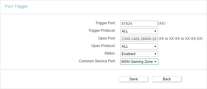
4.Leave the status as Enabled and click Save.
Note:
•You can add multiple port triggering rules as needed.
•The triggering ports can not be overlapped.
•If the application you need is not listed in the Common Service Port list, please enter the parameters manually. You should verify the open ports the application uses first and enter them in Open Port field. You can input at most 5 groups of ports (or port sections). Every group of ports must be set apart with “,”. For example, 2000-2038, 2050-2051, 2085, 3010-3030.
7.3. DMZ
When a PC is set to be a DMZ (Demilitarized Zone) host in the local network, it is totally exposed to the internet, which can realize the unlimited bidirectional communication between internal hosts and external hosts. The DMZ host becomes a virtual server with all ports opened. When you are not clear about which ports to open in some special applications, such as IP camera and database software, you can set the PC to be a DMZ host.
Note:
DMZ is more applicable in the situation that users are not clear about which ports to open. When it is enabled, the DMZ host is totally exposed to the internet, which may bring some potential safety hazards. If DMZ is not in use, please disable it in time.
I want to:
Make the home PC join the internet online game without port restriction.
For example, due to some port restriction, when playing the online games, you can log in normally but cannot join a team with other players. To solve this problem, set your PC as a DMZ host with all ports opened.
How can I do that?
1.Assign a static IP address to your PC, for example 192.168.0.100.
2.Visit http://tplinkwifi.net, and log in with the username and password you set for the router.
3.Go to Forwarding > DMZ.
4.Select Enable and enter the IP address 192.168.0.100 in the DMZ Host IP Address filed.
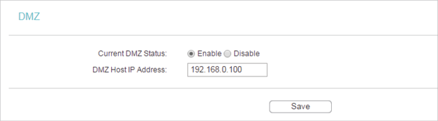
5.Click Save.
Done!
You’ve set your PC to a DMZ host and now you can make a team to game with other players.
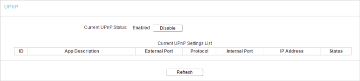
7.4. UPnP
The UPnP (Universal Plug and Play) protocol allows the applications or host devices to automatically find the front-end NAT device and send request to it to open the corresponding ports. With UPnP enabled, the applications or host devices on the local network and the internet can freely communicate with each other realizing the seamless connection of the network. You may need to enable the UPnP if you want to use applications for multiplayer gaming, peer-to-peer connections, real-time communication (such as VoIP or telephone conference) or remote assistance, etc.
Tips:
•UPnP is enabled by default in this router.
•Only the application supporting UPnP protocol can use this feature.
•UPnP feature needs the support of operating system (e.g. Windows Vista/ Windows 7/ Windows 8, etc. Some of operating system need to install the UPnP components).
For example, when you connect your Xbox to the router which is connected to the internet to play online games, UPnP will send request to the router to open the corresponding ports allowing the following data penetrating the NAT to transmit. Therefore, you can play Xbox online games without a hitch.

If necessary, you can follow the steps to change the status of UPnP.
1.Visit http://tplinkwifi.net, and log in with the username and password you set for the router.
2.Go to Forwarding > UPnP.
3.Click Disable or Enable according to your needs.
8. Security
This function allows you to protect your home network from cyber attacks and unauthorized users by implementing these network security functions.
8.1. Basic Security
1.Visit http://tplinkwifi.net, and log in with the username and password you set for the router.
2.Go to Security > Basic Security, and you can enable or disable the security functions.
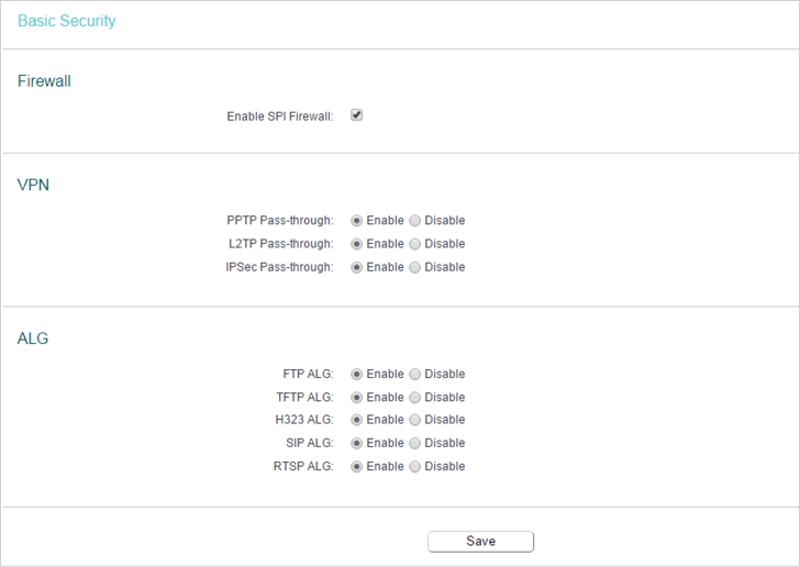
•Firewall — A firewall protects your network from internet attacks.
•Enable SPI Firewall — SPI (Stateful Packet Inspection, also known as dynamic packet filtering) helps to prevent cyber attacks by tracking more state per session. It validates that the traffic passing through the session conforms to the protocol. SPI Firewall is enabled by default.
•VPN — VPN Passthrough must be enabled if you want to allow VPN tunnels using IPSec, PPTP or L2TP protocols to pass through the router’s firewall.
•PPTP Pass-through — Point-to-Point Tunneling Protocol (PPTP) allows the Point-to-Point Protocol (PPP) to be tunneled through an IP network. If you want to allow PPTP tunnels to pass through the router, you can keep the default (Enabled).
•L2TP Pass-through — Layer 2 Tunneling Protocol (L2TP) is the method used to enable Point-to-Point sessions via the internet on the Layer 2 level. If you want to allow L2TP tunnels to pass through the router, you can keep the default (Enabled).
•IPSec Pass-through — Internet Protocol Security (IPSec) is a suite of protocols for ensuring private, secure communications over Internet Protocol (IP) networks, through the use of cryptographic security services. If you want to allow IPSec tunnels to pass through the router, you can keep the default (Enabled).
•ALG — It is recommended to enable Application Layer Gateway (ALG) because ALG allows customized Network Address Translation (NAT) traversal filters to be plugged into the gateway to support address and port translation for certain application layer “control/data” protocols such as FTP, TFTP, H323 etc.
•FTP ALG — To allow FTP clients and servers to transfer data across NAT, keep the default Enable.
•TFTP ALG — To allow TFTP clients and servers to transfer data across NAT, keep the default Enable.
•H323 ALG — To allow Microsoft NetMeeting clients to communicate across NAT, keep the default Enable.
•SIP ALG — To allow some multimedia clients to communicate across NAT, click Enable.
•RTSP ALG — To allow some media player clients to communicate with some streaming media servers across NAT, click Enable.
3.Click Save.
8.2. Advanced Security
1.Visit http://tplinkwifi.net, and log in with the username and password you set for the router.
2.Go to Security > Advanced Security, and you can protect the router from being attacked by ICMP-Flood, UDP Flood and TCP-SYN Flood.
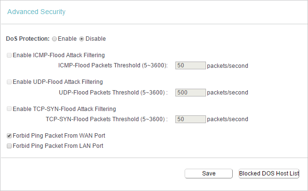
•DoS Protection — Denial of Service protection. Select Enable or Disable to enable or disable the DoS protection function. Only when it is enabled, will the flood filters be enabled.
Note:
Dos Protection will take effect only when the Statistics in System Tools > Statistics is enabled.
•Enable ICMP-FLOOD Attack Filtering — Tick the checkbox to enable or disable this function.
•ICMP-FLOOD Packets Threshold (5~3600) — The default value is 50. Enter a value between 5 ~ 3600. When the number of the current ICMP-FLOOD packets is beyond the set value, the router will startup the blocking function immediately.
•Enable UDP-FLOOD Filtering — Tick the checkbox to enable this function.
•UDP-FLOOD Packets Threshold (5~3600) — The default value is 500. Enter a value between 5 ~ 3600. When the number of the current UPD-FLOOD packets is beyond the set value, the router will startup the blocking function immediately.
•Enable TCP-SYN-FLOOD Attack Filtering -Tick the checkbox to enable or disable this function.
•TCP-SYN-FLOOD Packets Threshold (5~3600) — The default value is 50. Enter a value between 5 ~ 3600. When the number of the current TCP-SYN-FLOOD packets is beyond the set value, the router will startup the blocking function immediately.
•Ignore Ping Packet From WAN Port — The default setting is disabled. If enabled, the ping packet from the internet cannot access the router.
•Forbid Ping Packet From LAN Port — The default setting is disabled. If enabled, the ping packet from LAN cannot access the router. This function can be used to defend against some viruses.
3.Click Save.
4.Click Blocked DoS Host List to display the DoS host table by blocking.
9. Parental Controls
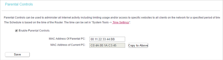
Parental Controls allows you to block inappropriate and malicious websites, and control access to specific websites at specific time for your children’s devices.
For example, you want the children’s PC with the MAC address 00:11:22:33:44:AA can access www.tp-link.com on Saturday only while the parent PC with the MAC address 00:11:22:33:44:BB is without any restriction.
1.Visit http://tplinkwifi.net, and log in with the username and password you set for the router.
2.Go to Parental Controls.
3.Tick the Enable Parental Controls checkbox, enter the MAC address 00:11:22:33:44:BB in the MAC Address of Parental PC field and then click Save.
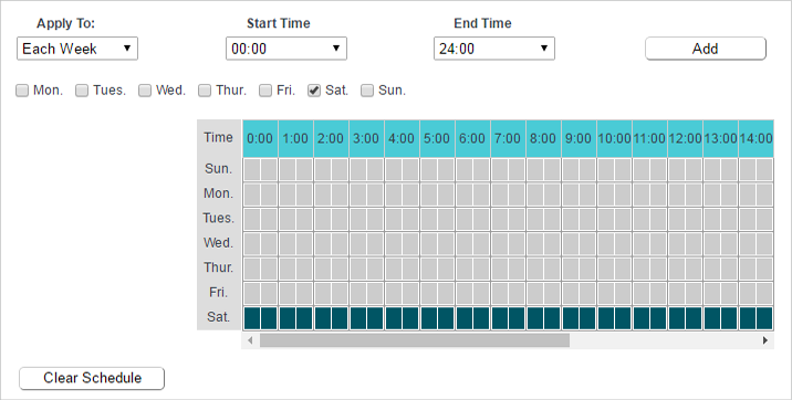
4.Enter 00:11:22:33:44:AA in the MAC Address 1 field.

5.Select Each Week from the Apply To drop-down list, and select Sat. Select 00:00 as the Start Time and Select 24:00 as the End Time. And then click Add.
6.Enter www.tp-link.com in the Add URL field. Click Add.
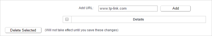
7.Click Save.
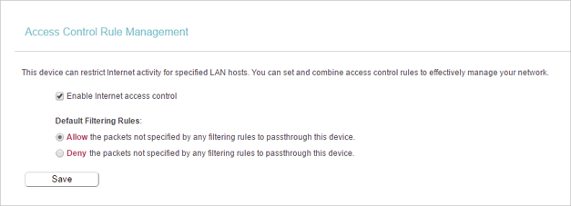
10. Access Control
Access Control is used to deny or allow specific client devices to access your network with access time and content restrictions.
I want to:
Deny or allow specific client devices to access my network with access tiem and content restrictions.
For example, If you want to restrict the internet activities of host with MAC address 00:11:22:33:44:AA on the LAN to access www.tp-link.com only, please follow the steps below:
How can I do that?
1.Visit http://tplinkwifi.net, and log in with the username and password you set for the router.
2.Go to Access Control > Host and configure the host settings:
1 )Click Add New.
2 )Select MAC Address as the mode type. Create a unique description (e.g. host_1) for the host in the Description field and enter 00:11:22:33:44:AA in the MAC Address filed.
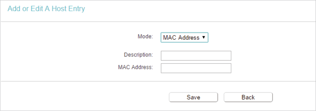
3 )Click Save.
3.Go to Access Control > Target and configure the target settings:
1 )Click Add New.
2 )Select URL Address as the mode type. Create a unique description (e.g. target_1) for the target in the Target Description field and enter the domain name, either the full name or the keywords (for example TP-Link) in the Add URL Address field. And then Click Add.
Note:
Any URL address with keywords in it (e.g. www.tp-link.com) will be blocked or allowed.
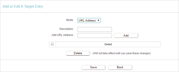
3 )Click Save.
4.Go to Access Control > Schedule and configure the schedule settings:
1 )Click Add New.
2 )Create a unique description (e.g. schedule_1) for the schedule in the Schedule Description field and set the day(s) and time period. And then click Add.
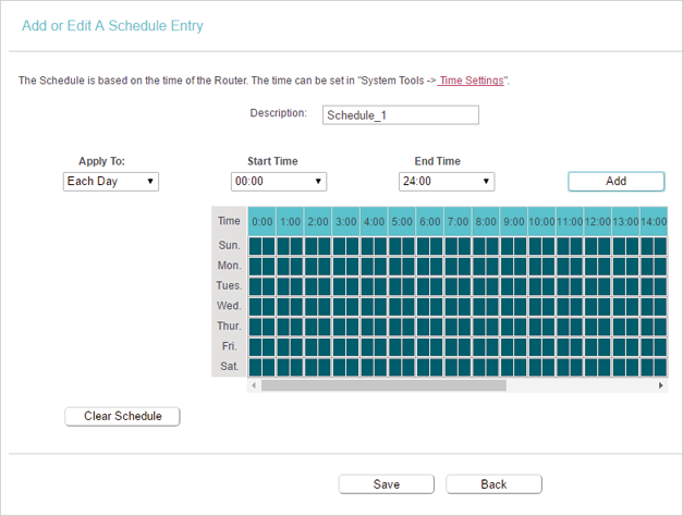
3 )Click Save.
5.Go to Access Control > Rule and add a new access control rule.
1 )Click Add New.
2 )Give a name for the rule in the Description field. Select host_1 from the LAN host drop-down list; select target_1 from the target drop-down list; select schedule_1 from the schedule drop-down list.
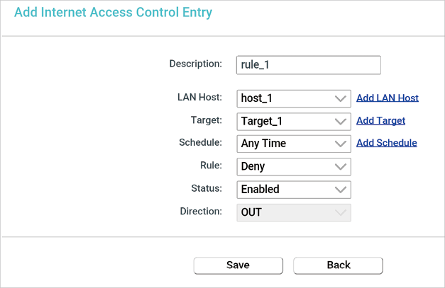
3 )Leave the status as Enabled as click Save.
Note:
When Target is set to be URL Address mode, the Direction field is OUT and not editable, which means the host can only visit or is not allowed to visit the URL address you set.
6.Select Enable Internet Access Control to enable Access Control function.
7.Select Allow the packets specified by any enabled access control policy to pass through the Router as the default filter policy and click Save.
Done!
Now only the specific host(s) can visit the target(s) within the scheduled time period.
Note:
When LAN Host and Target are both set to be the MAC Address mode, you need to set Protocol: ALL, TCP, UDP, ICMP. The default setting is ALL and it is recommended to keep the default setting.
11. Advanced Routing
Static Routing is a form of routing that is configured manually by a network administrator or a user by adding entries into a routing table. The manually-configured routing information guides the router in forwarding data packets to the specific destination.
11.1. Static Route List
1.Visit http://tplinkwifi.net, and log in with the username and password you set for the router.
2.Go to Advanced Routing > Static Route List.
•To add static routing entries:
1. Click Add New.
2.Enter the following information.
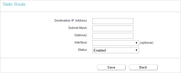
•Destination IP Address — The Destination Network is the address of the network or host that you want to assign to a static route.
•Subnet Mask — The Subnet Mask determines which portion of an IP address is the network portion, and which portion is the host portion.
•Gateway — This is the IP address of the default gateway device that allows the contact between the router and the network or host.
3.Select Enabled or Disabled for this entry on the Status drop-down list.
4.Click Save.
11.2. System Routing Table
1.Visit http://tplinkwifi.net, and log in with the username and password you set for the router.
2.Go to Advanced Routing > System Routing Table, and you can view all the valid route entries in use.
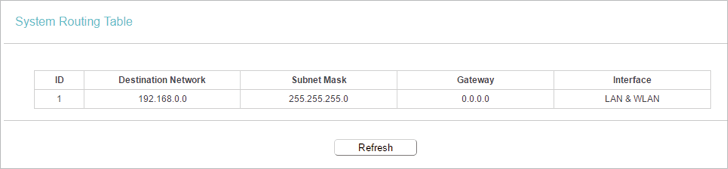
•Destination Network — The Destination Network is the address of the network or host to which the static route is assigned.
•Subnet Mask — The Subnet Mask determines which portion of an IP address is the network portion, and which portion is the host portion.
•Gateway — This is the IP address of the gateway device that allows for contact between the Router and the network or host.
•Interface — This interface tells you whether the Destination IP Address is on the LAN & WLAN (internal wired and wireless networks), or the WAN (Internet).
Click Refresh to refresh the data displayed.
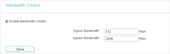
12. Bandwidth Control
1.Visit http://tplinkwifi.net, and log in with the username and password you set for the router.
2.Go to Bandwidth Control.
3.Tick the Enable Bandwidth Control checkbox, and configure the Egress Bandwidth and Ingress Bandwidth, and then click Save. The Egress/Ingress Bandwidth is the upload/download speed through the WAN port. The value should be less than 100,000Kbps.
4.Click Add New, fill in the blanks and click Save.
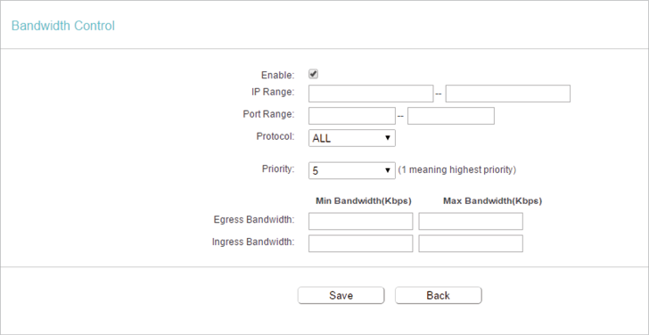
•IP Range — Interior PC address range. If both are blank or 0.0.0.0, the domain is noneffective.
•Port Range — The port range which the Interior PC access the outside PC. If all are blank or 0, the domain is noneffective.
•Protocol — Transport layer protocol, here there are ALL, TCP, UDP.
•Priority — Priority of Bandwidth Control rules. ‘1’ stands for the highest priority while ‘8’ stands for the lowest priority. The total Upstream/ Downstream Bandwidth is first allocated to guarantee all the Min Rate of Bandwidth Control rules. If there is any bandwidth left, it is first allocated to the rule with the highest priority, then to the rule with the second highest priority, and so on.
•Egress Bandwidth — The max and the min upload speed which through the WAN port.
•Ingress Bandwidth — The max and the min download speed through the WAN port.
13. IP & MAC Binding
IP & MAC Binding, namely, ARP (Address Resolution Protocol) Binding, is used to bind a network device’s IP address to its MAC address. This will prevent ARP spoofing and other ARP attacks by denying network access to a device with a matching IP address in the ARP list, but with an unrecognized MAC address.
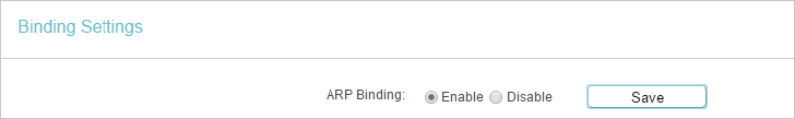
13.1. Binding Settings
1.Visit http://tplinkwifi.net, and log in with the username and password you set for the router.
2.Go to IP & MAC Binding > Binding Settings.
3.Select Enable for ARP Binding and click Save.
•To add IP & MAC Binding entries:
1.Click Add New.
2.Enter the MAC address and IP address.
3.Tick the Bind checkbox and click Save.
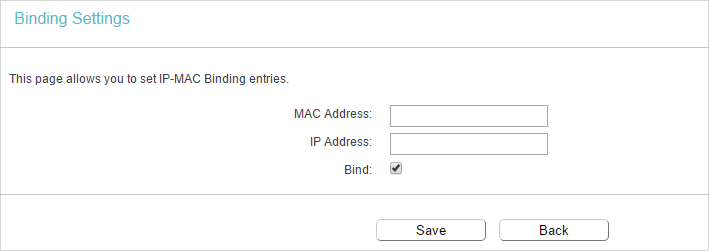
•To modify or delete an existing entry:
1.Select the desired entry in the table.
2.Click Edit or Delete Selected.
13.2. ARP List
To manage a device, you can observe the device on the LAN by checking its MAC address and IP address on the ARP list, and you can also configure the items. This page displays the ARP list which shows all the existing IP & MAC Binding entries.
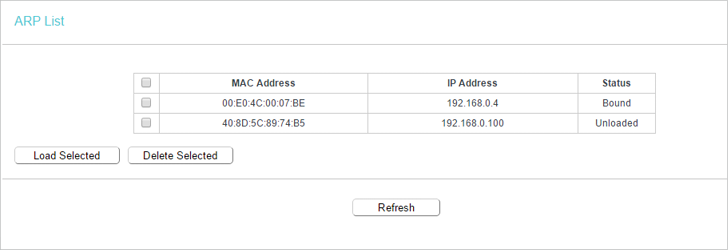
•MAC Address — The MAC address of the listed computer on the LAN.
•IP Address — The assigned IP address of the listed computer on the LAN.
•Status — Indicates whether or not the MAC and IP addresses are bound.
•Click the Load Selected button to load the selected items to the IP & MAC Binding list.
•Click the Delete Selected button to delete the selected items to the IP & MAC Binding list.
•Click the Refresh button to refresh all items.
Note:
An item can not be loaded to the IP & MAC Binding list if the IP address of the item has been loaded before.
14. Dynamic DNS
The router offers the DDNS (Dynamic Domain Name System) feature, which allows the hosting of a website, FTP server, or e-mail server with a fixed domain name (named by yourself) and a dynamic IP address. Thus your friends can connect to your server by entering your domain name no matter what your IP address is. Before using this feature, you need to sign up for DDNS service providers such as www.comexe.cn, www.dyndns.org, or www.noip.com. The Dynamic DNS client service provider will give you a password or key.
1.Visit http://tplinkwifi.net, and log in with the username and password you set for the router.
2.Go to Dynamic DNS.
Dyndns DDNS
If the dynamic DNS Service Provider you select is dyn.com/dns, the following page will appear.
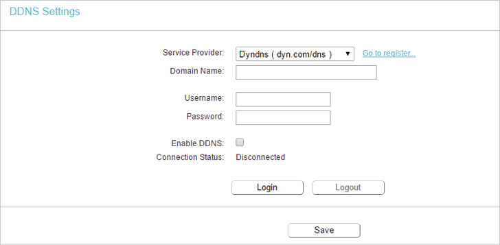
To set up for DDNS, follow these instructions:
1.Enter the Domain Name you received from dynamic DNS service provider here.
2.Enter the Username for your DDNS account.
3.Enter the Password for your DDNS account.
4.Click Login.
5.Click Save.
•Connection Status — The status of the DDNS service connection is displayed here.
•Logout — Click Logout to log out of the DDNS service.
No-IP DDNS
If the dynamic DNS Service Provider you select is www.noip.com, the following page will appear.
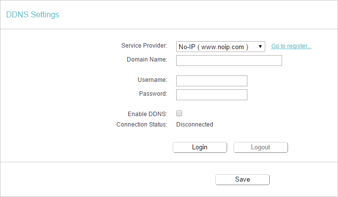
To set up for DDNS, follow these instructions:
1.Enter the Domain Name you received from dynamic DNS service provider.
2.Enter the Username for your DDNS account.
3.Enter the Password for your DDNS account.
4.Click Login.
5.Click Save.
•Connection Status — The status of the DDNS service connection is displayed here.
•Logout — Click Logout to log out of the DDNS service.
Comexe DDNS
If the dynamic DNS Service Provider you select is www.comexe.cn, the following page will appear.
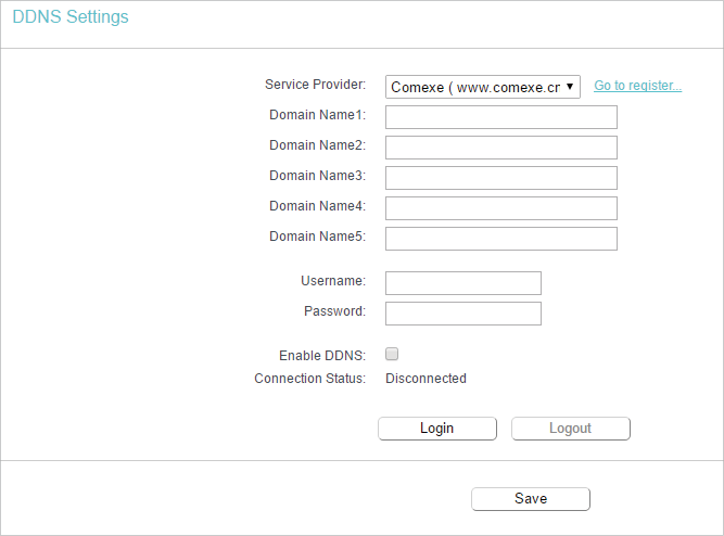
To set up for DDNS, follow these instructions:
1.Enter the Domain Name received from your dynamic DNS service provider.
2.Enter the Username for your DDNS account.
3.Enter the Password for your DDNS account.
4.Click Login.
5.Click Save.
•Connection Status — The status of the DDNS service connection is displayed here.
•Logout — Click Logout to log out of the DDNS service.
15. IPv6
This function allows you to enable IPv6 function and set up the parameters of the router’s Wide Area Network (WAN) and Local Area Network (LAN).
15.1. IPv6 Status
1.Visit http://tplinkwifi.net, and log in with the username and password you set for the router.
2.Go to IPv6 > IPv6 Status, and you can view the current IPv6 status information of the router.
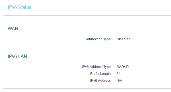
•WAN — This section shows the current IPv6 Connection Type.
•TPv6 LAN — This section shows the current IPv6 information of the router’s LAN port, including IPv6 Address Type, Prefix Length and IPv6 Address.
15.2. IPv6 WAN
1.Visit http://tplinkwifi.net, and log in with the username and password you set for the router.
2.Go to IPv6 > IPv6 WAN. Select Enable IPv6.
3.Select the WAN Connection Type and fill in the blanks according to your ISP, and then click Save.
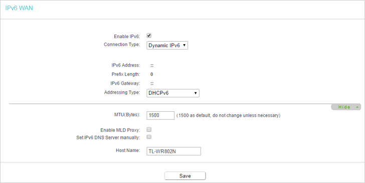
•Dynamic IPv6 — Connections which use dynamic IPv6 address assignment.
•Static IPv6 — Connections which use static IPv6 address assignment.
•PPPoEv6 — Connections which use PPPoEv6 that requires a username and password.
•Tunnel 6to4 — Connections which use 6to4 address assignment.
Dynamic IPv6
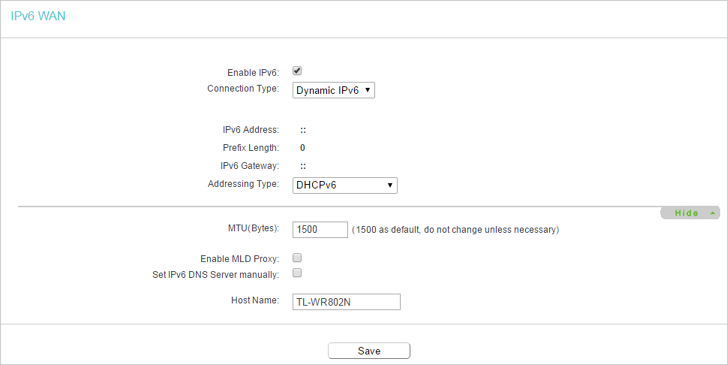
•IPv6 Address — The IPv6 address assigned by your ISP dynamically.
•Prefix Length — The length of IPv6 address prefix.
•IPv6 Gateway — Enter the default gateway provided by your ISP.
•Addressing Type — There are two types of assignation for IPv6 address: SLAAC (Stateless address auto-configuration) and DHCPv6 (Dynamic Host Configuration Protocol for IPv6) Server.
•MTU(Bytes) — The normal MTU (Maximum Transmission Unit) value for most Ethernet networks is 1500 Bytes. For some ISPs, you may need to modify the MTU. But this is rarely required, and should not be done unless you are sure it is necessary for your ISP connection.
•Enable MLD Proxy — Enable the Multicast Listener Discovery (MLD) Proxy function if you need.
•Set IPv6 DNS Server manually — If your ISP gives you one or two DNS IPv6 addresses, select Set IPv6 DNS Server manually and enter the IPv6 DNS Server and Secondary IPv6 DNS Server into the correct fields. Otherwise, the DNS servers will be assigned from ISP dynamically.
Note:
If you get Address not found error when you access a Web site, it is likely that your DNS servers are set up improperly. You should contact your ISP to get DNS server addresses.
Static IPv6
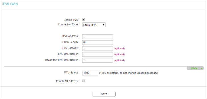
•IPv6 Address — Enter the IPv6 address provided by your ISP.
•Prefix Length — The length of IPv6 address prefix.
•IPv6 Gateway — Enter the default gateway provided by your ISP.
•IPv6 DNS Server— Enter the DNS IPv6 address provided by your ISP.
•Secondary IPv6 DNS Server — Enter another DNS IPv6 address provided by your ISP.
•MTU(Bytes) — The normal MTU (Maximum Transmission Unit) value for most Ethernet networks is 1500 Bytes. For some ISPs, you may need to modify the MTU. But this is rarely required, and should not be done unless you are sure it is necessary for your ISP connection.
•Enable MLD Proxy — Enable the Multicast Listener Discovery (MLD) Proxy function if you need.
PPPoEv6
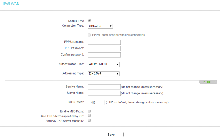
•PPP Username/Password — Enter the User Name and Password provided by your ISP. These fields are case-sensitive.
•Authentication Type – Choose one authentication type from AUTO-AUTH, PAP, CHAP and MS-CHAP.
•Addressing Type — There are two types of assignation for IPv6 address: SLAAC (Stateless address auto-configuration) and DHCPv6 (Dynamic Host Configuration Protocol for IPv6) Server.
•MTU(Bytes) — The normal MTU (Maximum Transmission Unit) value for most Ethernet networks is 1500 Bytes. For some ISPs, you may need to modify the MTU. But this is rarely required, and should not be done unless you are sure it is necessary for your ISP connection.
•Enable MLD Proxy — Enable the Multicast Listener Discovery (MLD) Proxy function if you need.
•Use IPv6 address specified by ISP — Input a static IPv6 address from the ISP.
•Set IPv6 DNS Server manually — Enter the IP address of the IPv6 DNS server and secondary IPv6 DNS server.
Tunnel 6to4
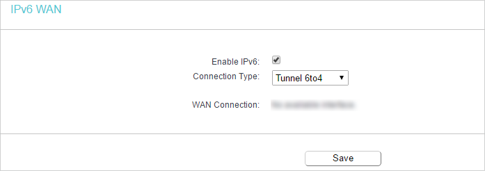
•WAN Connection — Display the available wan connection.
15.3. IPv6 LAN
1.Visit http://tplinkwifi.net, and log in with the username and password you set for the router.
2.Go to IPv6 > IPv6 LAN and configure the IPv6 LAN settings as needed.
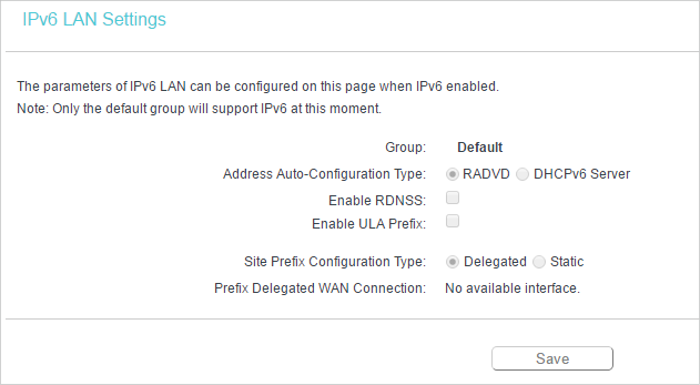
•Address Auto-Configuration Type — Select a type to assign IPv6 addresses to the computers in your LAN. RADVD and DHCPv6 Server are provided. I
•Site Prefix Configuration Type — The type of IPv6 address prefix.
•Delegated — Get the IPv6 address prefix from the ISP automatically, and the device will delegate it to the LAN.
•Static — Configure the Site Prefix and Site Prefix Length manually. Please contact your ISP to get more information before you configure them.
Note:
If your IPv6 wan connection type is “Tunnel 6to4”, the Site Prefix Configuration Type should be “Static” to make sure “Tunnel 6to4” works properly.
16. System Tools
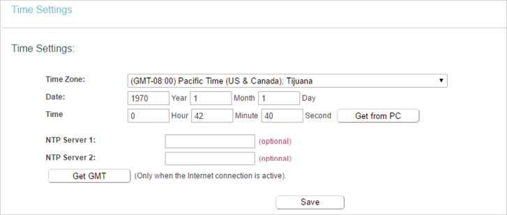
16.1. Time Settings
This page allows you to set the time manually or to configure automatic time synchronization. The router can automatically update the time from an NTP server via the internet.
1.Visit http://tplinkwifi.net, and log in with the username and password you set for the router.
2.Go to System Tools > Time Settings.
•To set time manually:
1.Select your local Time Zone.
2.Enter the Date in Month/Day/Year format.
3.Enter the Time in Hour/Minute/Second format.
4.Click Save.
•To set time automatically:
5.Select your local Time Zone.
6.Enter the address or domain of the NTP Server 1 or NTP Server 2.
7.Click Get GMT to get time from the internet if you have connected to the internet.
•To set Daylight Saving Time:
1.Select Enable Daylight Saving.
2.Select the start time from the drop-down list in the Start fields.
3.Select the end time from the drop-down list in the End fields.
4.Click Save.
Note:
This setting will be used for some time-based functions such as firewall. You must specify your time zone once you log in to the router successfully; otherwise, time-based functions will not take effect.
16.2. Diagnostic
Diagnostic is used to test the connectivity between the router and the host or other network devices.
1.Visit http://tplinkwifi.net, and log in with the username and password you set for the router.
2.Go to System Tools > Diagnostic.
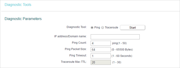
•Diagnostic Tool — Select one diagnostic tool.
•Ping — This diagnostic tool troubleshoots connectivity, reachability, and name resolution to a given host or gateway.
•Tracerouter — This diagnostic tool tests the performance of a connection.
Note:
You can use ping/traceroute to test both numeric IP address or domain name. If pinging/tracerouting the IP address is successful, but pinging/tracerouting the domain name is not, you might have a name resolution problem. In this case, ensure that the domain name you are specifying can be resolved by using Domain Name System (DNS) queries.
•IP Address/Domain Name — Enter the destination IP address (such as 192.168.0.1) or Domain name (such as www.tp-link.com).
•Pings Count — The number of Ping packets for a Ping connection.
•Ping Packet Size — The size of Ping packet.
•Ping Timeout — Set the waiting time for the reply of each Ping packet. If there is no reply in the specified time, the connection is overtime.
•Traceroute Max TTL — The max number of hops for a Traceroute connection.
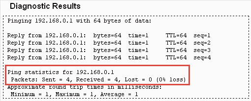
3.Click Start to check the connectivity of the internet.
4.The Diagnostic Results page displays the diagnosis result. If the result is similar to the following figure, the connectivity of the internet is fine.
16.3. Firmware Upgrade
TP-Link is dedicated to improving and richening the product features, giving users a better network experience. We will release the latest firmware at TP-Link official website
www.tp-link.com. You can download the lastest firmware file from the Support page of our website and upgrade the firmware to the latest version.
1.Download the latest firmware file for the router from our website www.tp-link.com.
2.Visit http://tplinkwifi.net, and log in with the username and password you set for the router.
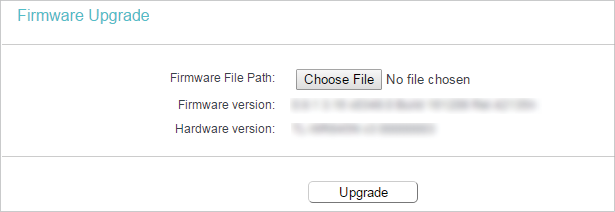
3.Go to System Tools > Firmware Upgrade.
4.Click Choose File to locate the downloaded firmware file, and click Upgrade.
16.4. Factory Defaults
1.Visit http://tplinkwifi.net, and log in with the username and password you set for the router.
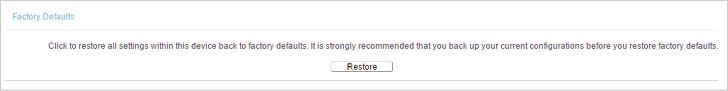
2.Go to System Tools > Factory Defaults. Click Restore to reset all settings to the default values.
•Default Username: admin
•Default Password: admin
•Default IP Address: 192.168.0.1
•Default Subnet Mask: 255.255.255.0
16.5. Backup & Restore
The configuration settings are stored as a configuration file in the router. You can backup the configuration file in your computer for future use and restore the router to the previous settings from the backup file when needed.
1.Visit http://tplinkwifi.net, and log in with the username and password you set for the router.
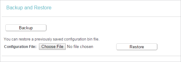
2.Go to System Tools > Backup & Restore.
•To backup configuration settings:
Click Backup to save a copy of the current settings in your local computer. A “.bin“ file of the current settings will be stored in your computer.
•To restore configuration settings:
1.Click Choose File to locate the backup configuration file stored in your computer, and click Restore.
2.Wait a few minutes for the restoring and rebooting.
Note:
During the restoring process, do not power off or reset the router.
16.6. Reboot
Some settings of the router will take effect only after rebooting, including:
•Change the LAN IP Address (system will reboot automatically).
•Change the DHCP Settings.
•Change the Working Modes.
•Change the Web Management Port.
•Upgrade the firmware of the router (system will reboot automatically).
•Restore the router to its factory defaults (system will reboot automatically).
•Update the configuration with the file (system will reboot automatically).
1.Visit http://tplinkwifi.net, and log in with the username and password you set for the router.
2.Go to System Tools > Reboot.
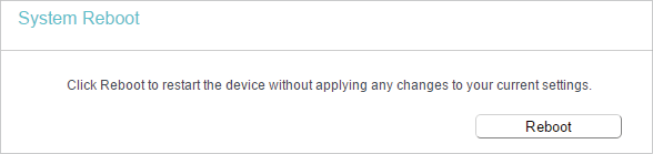
•To reboot manually
Click Reboot, and wait a few minutes for the router to rebooting.
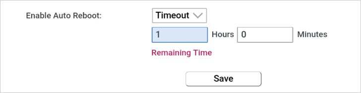
•To reboot automatically
•Select Timeout in the drop-down list of Enable Auto Reboot and specify a time period (1-72hours), then the router will reboot automatically after every this interval.
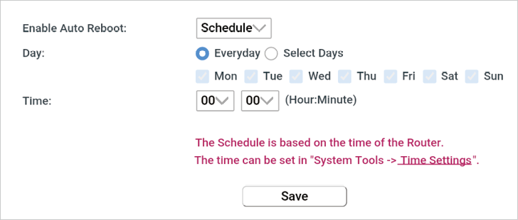
•Select Schedule in the drop-down list of Enable Auto Reboot and specify the Time when the router reboots and Day which to decide how often it reboots.
16.7. Account Management
1.Visit http://tplinkwifi.net, and log in with the username and password you set for the router.
2.Go to System Tools > Administrator, and focus on the Account Management section. You can change the factory default username and password of the router.
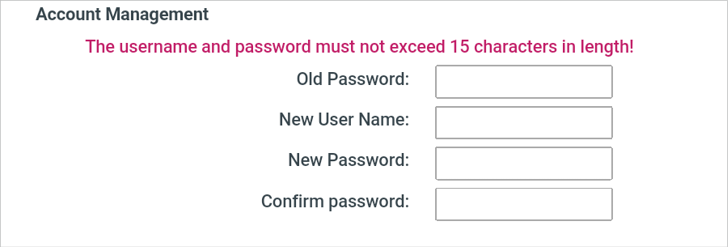
It is strongly recommended that you change the default username and password of the router, for all users that try to access the router’s web-based utility or Quick Setup will be prompted for the router’s username and password.
Note:
The new username and password must not exceed 15 characters and not include any spacing.
3.Click Save.
16.8. Local Management
This feature allows you to block computers on the LAN from accessing the router by using the MAC/IP-based authentication.
1.Visit http://tplinkwifi.net, and log in with the username and password you set for the router.
2.Go to System Tools > Administrator, and focus on the Service Configuration section.
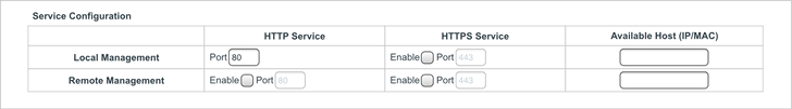
•Allow all LAN conencted devices to manage the router locally
1.Keep the Available Host (IP/MAC) empty, which means you don’t specify any host to manage the router.
2.If you want to access the router via both HTTPS and HTTP, please tick the Enable checkbox in HTTPS Service column. Otherwise, keep it disbled.
3.Keep the local management port as default if you don’t know which port to use.
4.Click Save.
Note:
If the web management port conflicts with the one used for Virtual Server entry, the entry will be automatically disabled after the setting is saved.
•Allow a specific device to manage the router locally
1.Enter the IP or MAC address of the host that you want to manage the router in the Available Host (IP/MAC) entry. The format of the MAC address is XX:XX:XX:XX:XX:XX (X is any hexadecimal digit).
2.If you want to access the router via both HTTPS and HTTP, please tick the Enable box in HTTPS Service column. Otherwise, keep it disbled.
3.Keep the Port as default if you don’t know which port to use.
4.Click Save.
Note:
If your PC is blocked but you want to access the router again, press and hold the Reset button to reset the router to the factory defaults.
•Certificate
Download and install the certificate for management via HTTPS if you need it. Once the certificate is installed, warnings will not pop up when you access the router via HTTPS.

16.9. Remote Management
This feature allows you to manage your router from a remote location via the internet.
1.Visit http://tplinkwifi.net, and log in with the username and password you set for the router.
2.Go to System Tools > Administrator, and focus on the Service Configuration section.
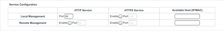
•Forbid all devices to manage the router remotely
Do not tick the Enable checkbox in both HTTP Service and HTTPS Service.
•Allow all devices to manage the router remotely
1.Tick the Enable checkbox in HTTP Service.
2.If you want to access the router via both HTTPS and HTTP, please tick the Enable checkbox in HTTPS Service column. Otherwise, keep it disbled.
3.For higher security, you can change the remote management web port by entering a number between 1024 and 65534.
4.Click Save.
•Allow a specific device to manage the router remotely
1.Tick the Enable checkbox in HTTP Service.
2.If you want to access the router via both HTTPS and HTTP, please tick the Enable checkbox in HTTPS Service column. Otherwise, keep it disbled.
3.For higher security, you can change the remote management web port by entering a number between 1024 and 65534.
4.Enter the IP or MAC address of the host that you want to manage the router in the Available Host (IP/MAC) entry. The format of the MAC address is XX:XX:XX:XX:XX:XX (X is any hexadecimal digit).
5.Click Save.
•Certificate
Download and install the certificate for management via HTTPS if you need it. Once the certificate is installed, warnings will not pop up when you access the router via HTTPS.
Note:
•To access the router, enter your router’s WAN IP address in your browser’s address bar, followed by a colon and the custom port number. For example, if your router’s WAN address is 202.96.12.8, and the port number used is 8080, please enter http://202.96.12.8:8080 in your browser. Later, you may be asked for the router’s password. After successfully entering the username and password, you will be able to access the router’s web management page.
•Be sure to change the router’s default password for security purposes.
16.10. System Log
1.Visit http://tplinkwifi.net, and log in with the username and password you set for the router.
2.Go to System Tools > System Log, and you can view the logs of the router.
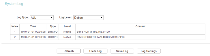
•Loge Type -By selecting the log type, only logs of this type will be shown.
•Log Level — By selecting the log level, only logs of this level will be shown.
•Refresh — Refresh the page to show the latest log list.
•Clear Log — All the logs will be deleted from the router permanently, not just from the page.
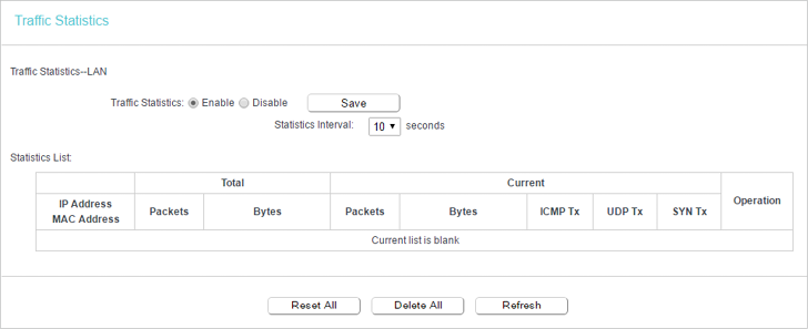
16.11. Statistics
1.Visit http://tplinkwifi.net, and log in with the username and password you set for the router.
2.Go to System Tools > Traffic Statistics.
3.Select Enable and click Save. You can view the network traffic of each PC on the LAN, including total traffic and the value of the last Packets Statistic interval in seconds.
17. Log out
Click Logout at the bottom of the main menu, and you will log out of the web management page and return to the login window.
Wi-Fi роутеры играют важную роль в нашей повседневной жизни, обеспечивая нам беспроводное соединение с интернетом. TP-Link AC1200 — одна из самых популярных моделей на рынке, предлагающая высокую скорость передачи данных и отличное качество сигнала. Но как настроить этот роутер, чтобы он работал наиболее эффективно? В этой статье мы подробно рассмотрим процесс настройки Wi-Fi роутера TP-Link AC1200, чтобы вы смогли быстро и легко настроить его под свои нужды.
Первым шагом в настройке роутера является подключение его к сети электропитания и к вашему модему по средством провода Ethernet. После этого вы можете запустить веб-браузер на вашем компьютере и ввести IP-адрес роутера, который указан в инструкции. Войдите в административную панель роутера с помощью предоставленного вами пароля.
После входа в административную панель TP-Link AC1200 вы увидите различные вкладки и настройки. Первым делом рекомендуется изменить имя вашей беспроводной сети (SSID) и пароль, чтобы обезопасить подключение к вашему роутеру. Вкладка «Беспроводные настройки» позволяет вам это сделать. Не забудьте выбрать безопасный пароль, состоящий из букв, цифр и специальных символов.
Не менее важная настройка — это выбор частоты работы роутера. Вкладка «Настройки Wi-Fi» позволяет вам выбрать между 2,4 ГГц и 5 ГГц частотами. 2,4 ГГц предлагает более широкий охват, но может столкнуться с перегруженной сетью Wi-Fi в вашем окружении. 5 ГГц частота, с другой стороны, обеспечивает более быструю скорость передачи данных при низком уровне помех. Выберите ту, которая лучше подходит для ваших нужд.
Настроить и оптимизировать Wi-Fi роутер TP-Link AC1200 не сложнее, чем кажется на первый взгляд. Придерживаясь этого подробного руководства, вы сможете быстро подключиться к интернету и наслаждаться высококачественным беспроводным подключением. Удачной настройки!
Содержание
- Как подробно настроить Wi-Fi роутер TP-Link AC1200
- Установка оборудования и подключение к сети
- Настройка основных параметров роутера
- Настройка безопасности и авторизации
Как подробно настроить Wi-Fi роутер TP-Link AC1200
Настройка Wi-Fi роутера TP-Link AC1200 важна для обеспечения безопасного и стабильного интернет-соединения. В этом руководстве мы подробно рассмотрим все необходимые шаги для настройки данного модели роутера.
1. Подключение роутера
Перед началом настройки необходимо подключить роутер к электропитанию и внешнему интернет-провайдеру. Подключите один конец Ethernet-кабеля к порту «WAN» на роутере, а другой конец — к модему или проводному интернет-провайдеру. После этого включите роутер в сеть.
2. Подключение к роутеру
Для настройки роутера вам потребуется подключиться к его административному интерфейсу. Откройте веб-браузер на устройстве, подключенном к роутеру, и введите адрес «tplinkwifi.net» в адресную строку. Введите свои учетные данные, если они требуются, чтобы войти в панель управления роутером.
3. Настройка базовых параметров
После успешного входа вы увидите панель управления роутером. Здесь вы можете настроить основные параметры, такие как имя сети (SSID) и пароль. В разделе «Wireless» найдите настройки Wi-Fi сети. Установите желаемое имя сети и пароль для доступа к сети. Не забудьте сохранить изменения.
4. Настройка безопасности Wi-Fi
Для обеспечения безопасной работы Wi-Fi сети рекомендуется настроить соответствующие параметры безопасности. В панели управления роутером найдите настройки безопасности Wi-Fi и выберите подходящий протокол шифрования, такой как WPA2-PSK. Установите сложный пароль, состоящий из букв, цифр и специальных символов. Сохраните настройки.
5. Дополнительные настройки
В зависимости от ваших потребностей и предпочтений, вы можете настроить дополнительные параметры роутера, такие как QoS (Quality of Service), управление родительским контролем, гостевую сеть и другие. Исследуйте панель управления роутером и внесите соответствующие настройки в соответствии с вашими потребностями.
6. Проверка подключения
После завершения всех настроек роутера, проверьте подключение к Интернету на устройствах, подключенных к Wi-Fi сети. Убедитесь, что все устройства успешно подключены и имеют доступ к Интернету. В случае проблем, перезагрузите роутер и проверьте все настройки еще раз.
Теперь вы полностью настроили свой Wi-Fi роутер TP-Link AC1200 и готовы пользоваться стабильным и безопасным интернет-соединением.
Установка оборудования и подключение к сети
Перед началом установки и настройки Wi-Fi роутера TP-Link AC1200 следует убедиться в наличии всех необходимых компонентов:
- Wi-Fi роутер TP-Link AC1200
- Инструкция по эксплуатации
- Проводной интернет кабель (Ethernet-кабель)
- Интернет-модем
- Интернет-провайдер (ISP)
- Компьютер или смартфон для настройки
После проверки наличия всех компонентов, можно приступать к установке:
- Выключите компьютер или смартфон, а также интернет-модем.
- Подключите интернет-модем к роутеру с помощью Ethernet-кабеля. Один конец кабеля необходимо вставить в порт WAN (обычно выделен разъемом другого цвета) на роутере, а другой конец — в выходной порт на модеме.
- Включите интернет-модем и подождите, пока он загрузится и установит соединение с вашим интернет-провайдером. Обычно для этого требуется несколько минут.
- Подключите роутер к источнику питания с помощью прилагаемого адаптера питания и включите его. Роутер автоматически запустится и начнет работу.
- Дождитесь загрузки роутера (обычно индикаторы на самом роутере перестанут мигать) и после этого можно приступить к настройке Wi-Fi сети.
В процессе установки рекомендуется следовать инструкциям, прилагаемым к Wi-Fi роутеру TP-Link AC1200, а также обращаться к руководству вашего интернет-провайдера, если возникают проблемы с подключением к сети.
Настройка основных параметров роутера
Шаг 1: Подключите роутер к источнику питания и дождитесь, пока он полностью загрузится. Убедитесь, что индикаторы светятся, указывая на активное подключение.
Шаг 2: Подключите компьютер или ноутбук к роутеру с помощью Ethernet-кабеля или через Wi-Fi.
Шаг 3: Откройте веб-браузер и введите в адресной строке IP-адрес роутера. Обычно это 192.168.0.1 или 192.168.1.1. Нажмите клавишу Enter, чтобы перейти к странице входа в роутер.
Шаг 4: Введите имя пользователя и пароль для доступа к настройкам роутера. Если вы не изменили эти данные ранее, используйте стандартные значения, указанные в руководстве пользователя. Нажмите кнопку Войти.
Шаг 5: После успешного входа в панель управления роутера настройте основные параметры, такие как имя Wi-Fi сети (SSID) и пароль. Обязательно защитите сеть Wi-Fi с помощью шифрования WPA2-PSK и выберите сложный пароль для безопасности.
Шаг 6: Сохраните настройки и перезагрузите роутер, чтобы применить изменения. После перезагрузки проверьте работу Wi-Fi сети, подключився к ней с другого устройства.
Примечание: Данные инструкции являются общими и могут отличаться в зависимости от модели и версии firmware. Если у вас возникли проблемы или вопросы, обратитесь к руководству пользователя для получения дополнительной информации.
Настройка безопасности и авторизации
При настройке Wi-Fi роутера TP-Link AC1200 очень важно обеспечить безопасность вашей сети и защитить ее от несанкционированного доступа. Для этого вы можете использовать следующие методы:
|
1. Зашифруйте свою Wi-Fi сеть Включите функцию WPA2 или WPA3 (рекомендуется) для шифрования вашей Wi-Fi сети. Это защитит вашу сеть от злоумышленников и предотвратит несанкционированный доступ. |
|
2. Задайте сложный пароль для доступа к Wi-Fi Создайте надежный пароль для доступа к вашей Wi-Fi сети. Используйте комбинацию букв (в верхнем и нижнем регистрах), цифр и символов, чтобы сделать пароль максимально сложным и надежным. |
|
3. Измените стандартное имя и пароль для доступа к административной панели роутера Измените стандартное имя пользователя и пароль для доступа к административной панели вашего роутера. Это поможет предотвратить несанкционированный доступ к настройкам роутера. |
|
4. Включите фильтрацию MAC-адресов Фильтрация MAC-адресов позволяет разрешить или запретить доступ к Wi-Fi сети только устройствам с определенными MAC-адресами. Это дополнительный уровень безопасности, который ограничит доступ к вашей сети. |
Следуя этим рекомендациям, вы сможете обеспечить безопасность вашей Wi-Fi сети и защититься от несанкционированного доступа.
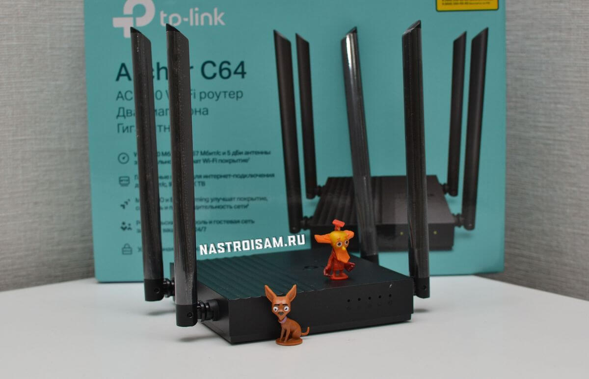
Думаю, не ошибусь, если скажу, что бОльшего разнообразия беспроводных маршрутизаторов, чем у TP-Link нет ни у одной компании-производителя. Сегодня я расскажу про TP-Link Archer C64 — это один из лучших Wi-Fi роутеров в ценовом диапазоне 2500-3000 рублей. А уж если у Вас получится взять его по какой-нибудь скидке за 2000 рублей, то за эту стоимость это будет вообще идеал для обычного, непритязательного пользователя. Почему я о нём так хорошо отзываюсь — да потому, что Archer C64 простоял у меня на долгосрочном тесте аж два месяца и за это время с ним не было ни единого сбоя и не возникло ни одной, даже простейшей проблемы.
Основной процессор (CPU) — TP-Link TP1900BN 1,2 ГГц (он же SoC MediaTek MT7626).
Оперативная память (RAM) — 32 МБ
Постоянная память (Flash) — 4 МБ
Wi-Fi:
Мощность передатчика — 20 dBm
Антенны — 4 x 5 bBi
— 2,4 ГГц: MT7761N 802.11b/g/n
— 5 ГГц: MT7762N 802.11a/n/ac
Порты:
Коммутатор Realtek RTL8367S
1 x WAN 100/1000 Мбит/с
4 x LAN 100/1000 Мбит/с
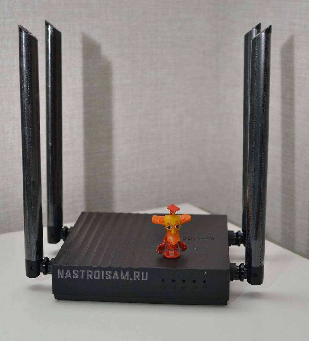
По железу, Archer C64 является практически двойником Archer C80. Основная разница между ними — это максимальная теоретически достижимая скорость. Дело в том, что у C64 беспроводная сеть работает в режиме 2×2 и позволяет достигать скорость 400 Мбит/с в диапазоне 2,4 ГГц и 867 Мбит/с в диапазоне 5 ГГц. А вот Арчер C80 работает по формуле 3×3 и у него скоростные показатели 600 Мбит/с и 1300 Мбит/с соответственно. Понятно, что таких скоростей не видать и в перспективе, потому, на мой взгляд, переплачивать за старшую модель нет абсолютно никакого смысла.
По производительности для большинства обычных задач этого «железа» хватит с лихвой, а вот для использования в офисе или в высоконагруженных домашних сетях стоит присмотреть что-то другое.
Возможности и впечатления
Первое, что подмечаешь — это компактность и лёгкость роутера. Его можно поставить горизонтально, а можно повесить вертикально на стену. Внешность — проще некуда: квадратная «рогатая» коробочка с пятью индикаторами с одной стороны и пятью Ethernet-портами с другой. На многих обзорах жаловались, что на корпусе TP-Link Archer C64 нет дополнительных отверстий для вентиляции. Честно говоря — они не особо то и нужны. Устройство сильно не греется даже под нагрузкой.
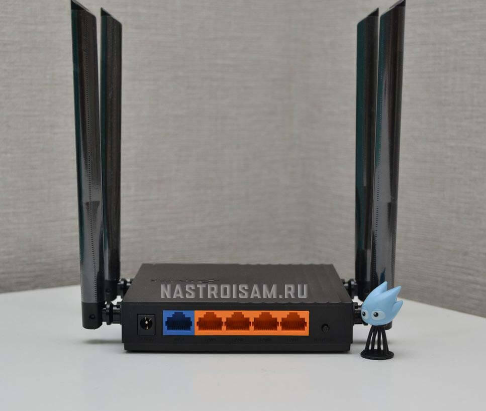
Установка и настройка традиционно простые для TP-Link. Всё легко выполняется и через веб-интерфейс с компьютера, и через мобильное приложение для смартфонов.
По работе за время долгосрочного тестирования о Archer C64 сплошные положительные впечатления. Мне удалось вытянуть на нём около 930 МБит\с через кабель и до 300 МБит\с по воздуху. Для дома это отличные скоростные показатели.
Зона покрытия Wi-Fi у TP-Link Archer C64 тоже порадовала. У меня он покрыл беспроводной сетью 80 кв. метров при условии расположения точки доступа в середине жилища. Благодаря MU-MIMO и Beamforming даже в дальнем углу квартиры, где традиционно плохой приём, в этот раз он был среднем. К примеру, более дорогой ASUS RT-AC1200 такого уже не осилил.
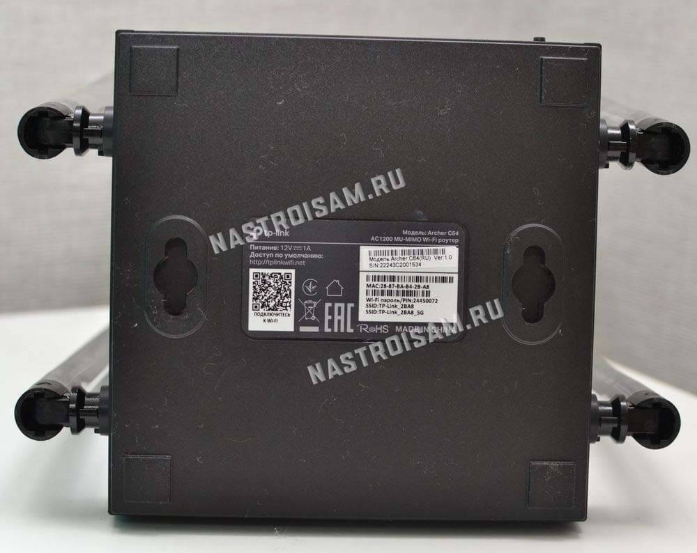
Особая фишка модели — поддержка OneMesh. Благодаря этой фишке, Вы сможете при необходимости расширить зону покрытия беспроводной сети в нужном направлении, купив расширитель. Причём это будет уже Mesh-сеть с всеми «плюшками» в виде роуминга и бесшовной сети.
Я однозначно буду рекомендовать роутер Archer C64 для большинства среднестатистических пользователей при его цене 2500 рублей и ниже. За такую цену — это отличный вариант.
Настройка TP-Link Archer C64
Для настройки устройства. сначала необходимо к нему подключиться кабелем или по Wi-Fi. Пароль беспроводной сети написан в наклейке на обратной стороне корпуса. Вход в веб-интерфейс роутера, как и на всех современных маршрутизаторах TP-Link Archer, выполняется через адрес tplinkwifi.net или через IP 192.168.0.1.
При первом подключении к роутеру от Вас потребуется придумать и указать пароль администратора:
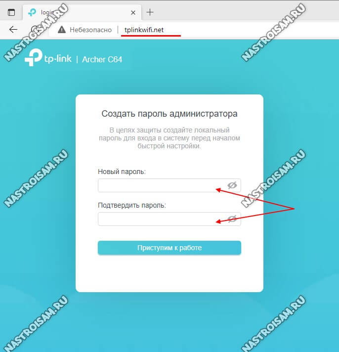
Старайтесь сделать его посложнее и длиной не менее 6-8 символов. После этого нажмите на кнопку «Приступить к работе».
Далее будет запущен мастер быстрой настройки маршрутизатора. В случае с Archer C64 он действительно удобный и позволяет полностью настроить все базовые функции.
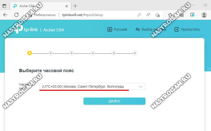
Выберите свой часовой пояс и нажмите кнопку «Далее».
Второй шаг — проверка подключения к Интернету. Подключите кабель провайдера к роутеру:
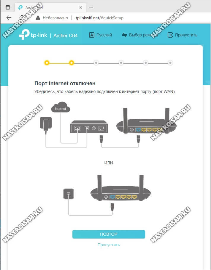
Если такой возможности нет — можно нажать на кнопку «Пропустить».
Третий шаг — настройка подключения роутера к Интернету. Вы можете выбрать свой город, провайдера и тип подключения:
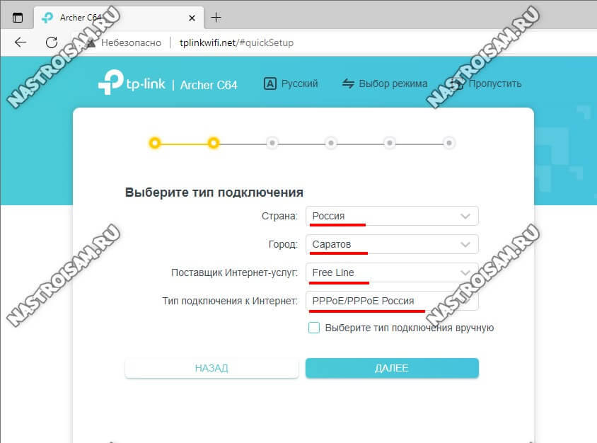
Если Вашего города или провайдера нет в списке — поставьте галочку «Выберите тип подключения». Появится список возможных вариантов подключения:
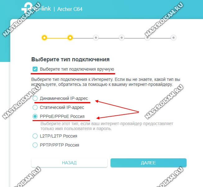
Наиболее распространённые в России варианты — это «Динамический IP-адрес» и «PPPoE». В первом случае дополнительных настроек подключения обычно не требуется, а вот в случае использования протокола PPPoE необходимо будет дополнительно указать имя пользователя и пароля на подключение, которые Вы получили у провайдера при заключении договора.
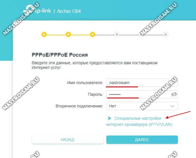
Обратите внимание, если Вам необходимо настроить цифровое телевидение IPTV через STB-приставку, то необходимо кликнуть на ссылку «Специальные настройки интернет-провайдера (IPTV/VLAN)». Откроются дополнительные параметры настройки:
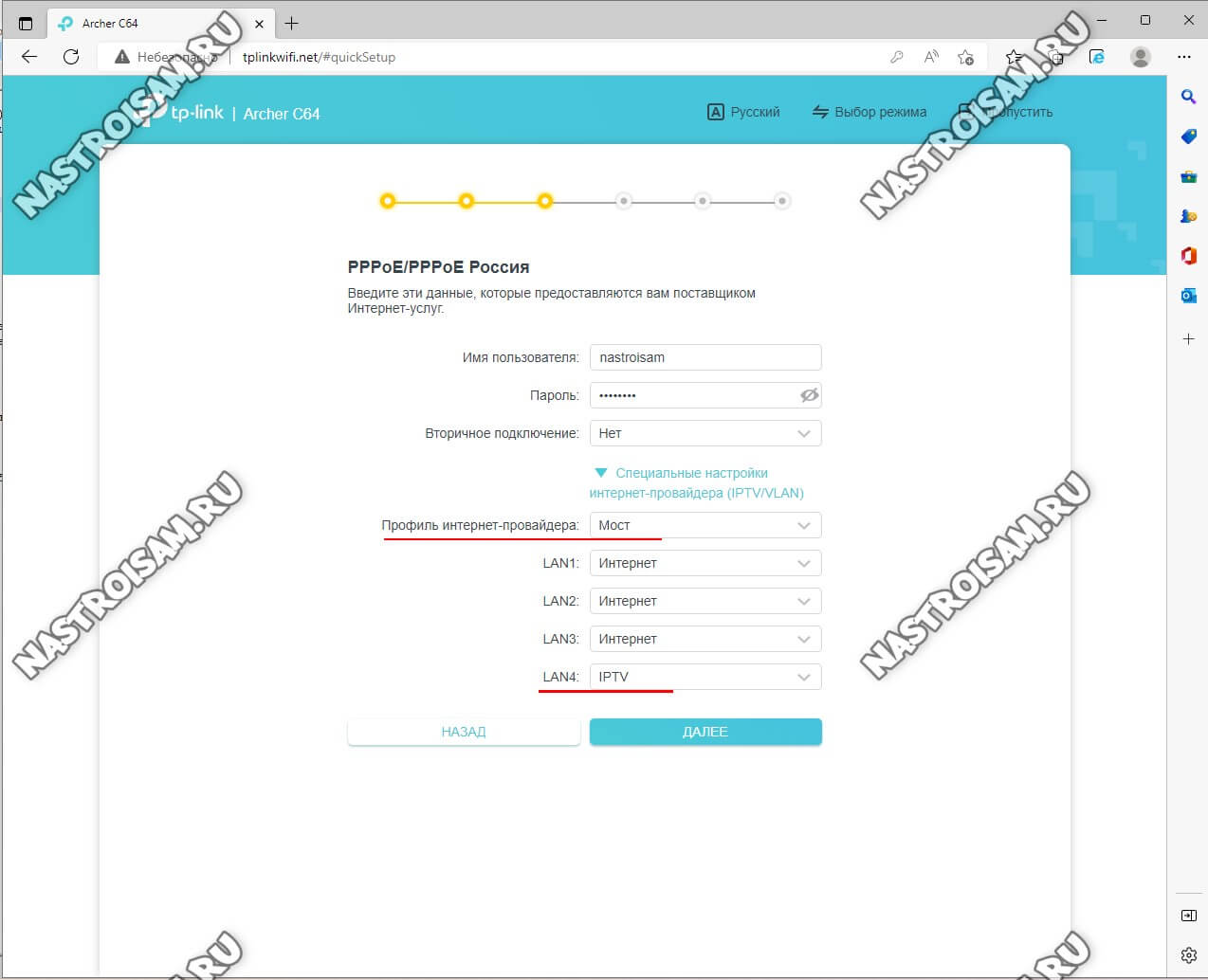
Здесь надо будет выбрать профиль провайдера — обычно это просто «Мост» (Bridge). Ниже надо будет для LAN-порта, в который включена ТВ-приставка поставить значение «IPTV».
Если у Вашего провайдера для работы цифрового телевидения надо указывать идентификатор VLAN ID (например, Ростелеком), тогда в поле выбора провайдера поставьте значение «Указать вручную». Добавится много разных настроек и полей для ввода:
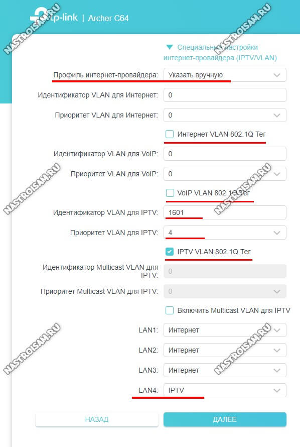
Вам надо поставить галку «IPTV VLAN 802.1Q Тег», а остальные надо снять (см. скриншот). Введите идентификатор VLAN ID для IPTV — его надо предварительно узнать в техподдержке устройства. Приоритет для VLAN — поставьте значение «4».
Ниже, напротив LAN-порта, в который включена приставка, поставьте значение IPTV.
Нажмите кнопку «Далее».
Будет выполнена проверка подключения к Интернету.
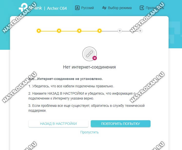
Если кабель провайдера подключен и Вы всё сделали правильно, то соединение поднимется. У меня же в примере кабель не подключен и потому я нажимаю на кнопку «Пропустить».
Переходим к настройке Wi-Fi на TP-Link Archer C64:
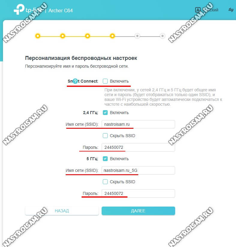
Здесь можно изменить используемые по умолчанию имя сети Вай-Фай и пароль для подключения к ней.
Так же можно активировать функцию «SmartConnect» — у Вас будет одно имя сети на оба диапазона и роутер будет сам следить за уровнем сигнала и переключать клиентов с диапазона на диапазон для достижения лучшей скорости.
После этого надо будет подтвердить сделанные изменения:
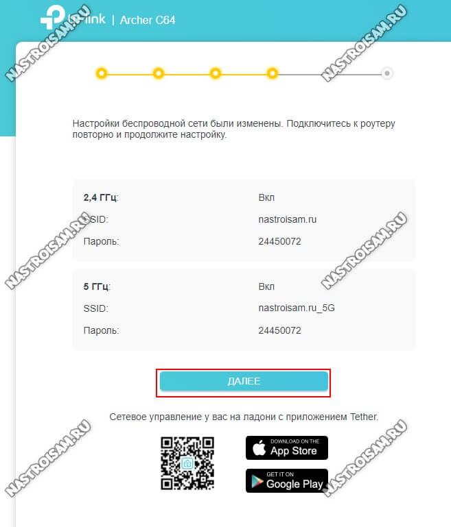
На этом этапе надо будет переподключиться к роутеру Archer C64 уже с новым именем сети и паролем.
Финальный этап — проверка всех выполененных настроек:
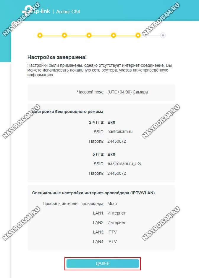
Нажимаем на кнопку «Далее». Базовая настройка TP-Link Archer C64 завершена, основной функционал настроен!
Как открыть порт на Archer C64
Для активного режима файлообменных программ, игр а так же видеорегистратора системы наблюдения часто требуется настроить проброс портов на роутере. В случае с программами и играми успешно справляется функция UPnP, которая по умолчанию включена на роутере:
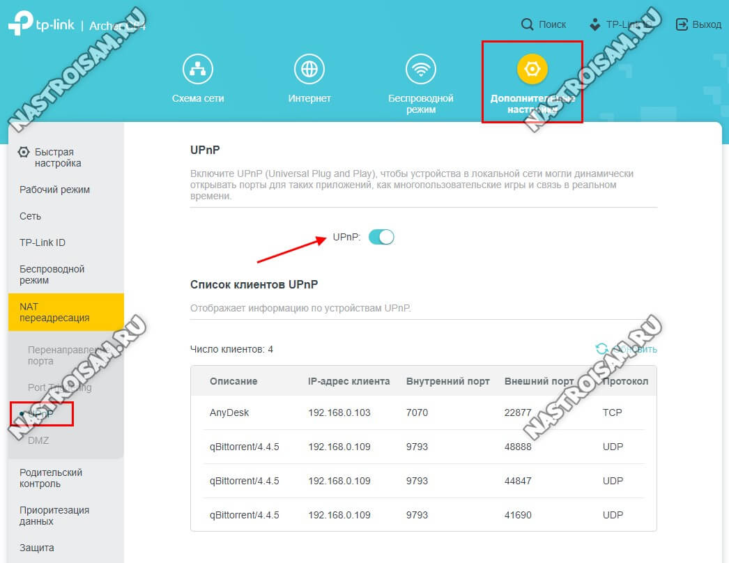
А вот для видеокамеры или видеорегистратора часто требуется открыть порт вручную. Для этого открываем «Дополнительные настройки» → «NAT переадресация» → «Перенаправление портов»:
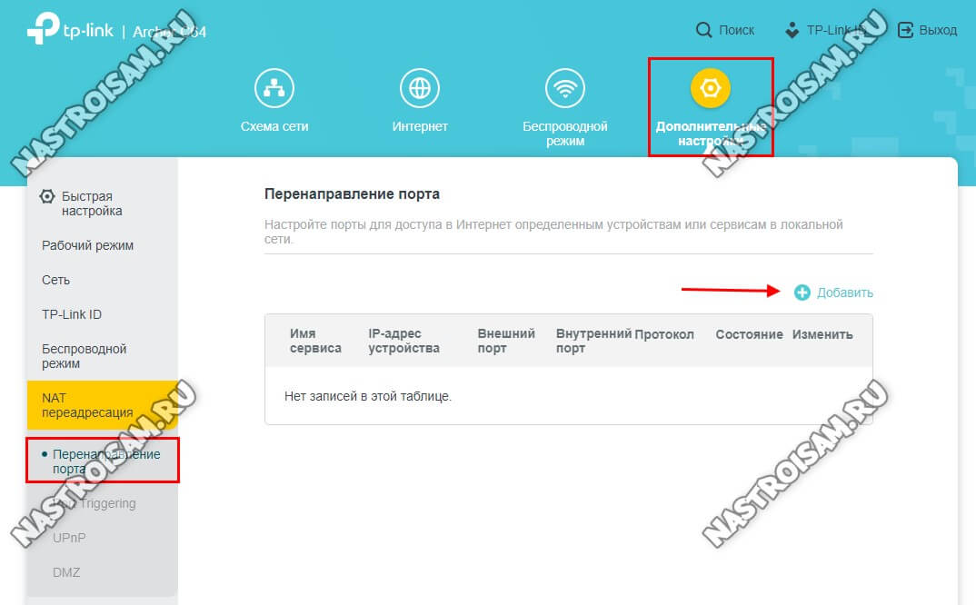
Нажимаем на кнопку «Добавить». Откроется окно «Перенаправление порта»:
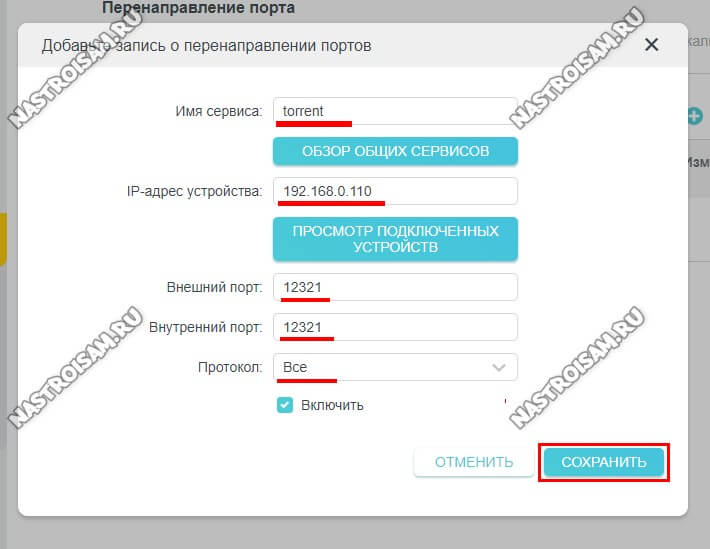
Указываем название для правила, IP-адрес устройства, для которого делаем проброс, номер внешнего и внутреннего порта, а так же используемый протокол. Нажимаем на кнопку «Сохранить».
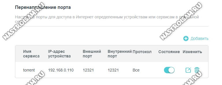
В таблице правил Перенаправления портов появится новая строчка.
Обновление прошивки роутера
Чтобы перепрошить TP-Link Archer C64 на новую прошивку, надо открыть «Дополнительные настройки» → «Система» → «Обновление встроенного ПО».
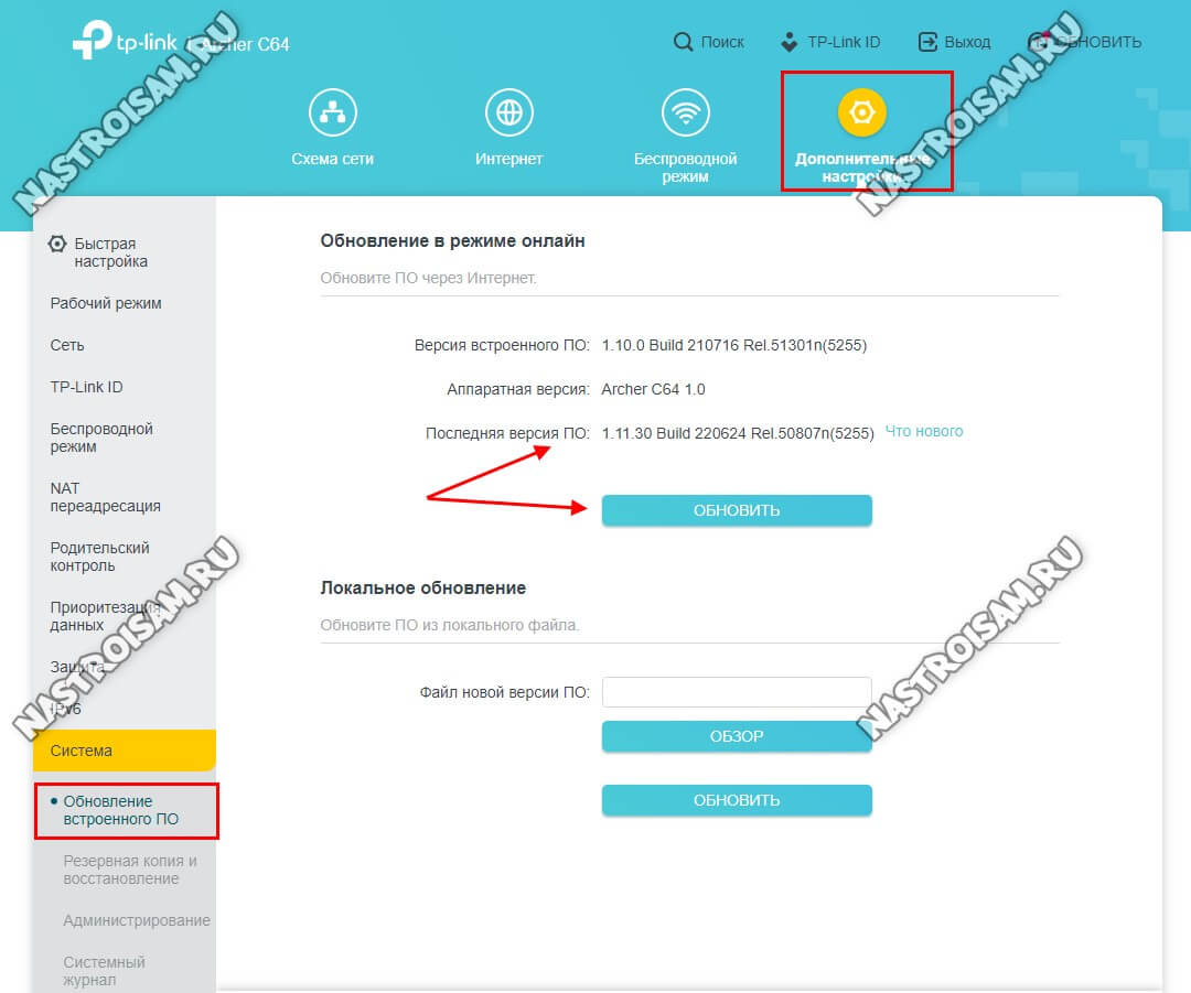
На большинстве современных маршрутизаторов TP-Link обновление прошивки можно сделать в режиме «Онлайн» при наличии активного Интернет-соединения. Роутер проверить на сервере наличие свежей версии и, если такая есть — предложит обновится. Достаточно будет нажать кнопку «Обновить» и дождаться перезагрузки роутера. Настройки он при этом не сбросит.
Если необходимо прошить роутер вручную — надо сначала скачать файл с прошивкой, потом в окне обновления нажать на кнопку «Обзор», указать устройству путь к файлу, после чего нажать кнопку «Обновить».