Basic Questions

To learn about clustering, it is a good idea to start with some basic questions and answers. Setting up clusters really is not as difficult as most administrators believe.
What is Clustering?
A cluster is a group of independent computers working together as a single system to ensure that mission-critical applications and resources are as highly-available as possible. The group of computers is managed as a single system, it shares a common namespace, and it is specifically designed to tolerate component failures. A cluster supports the addition or removal of components in a way that’s transparent to users.
The general concept in clustering is that there are nodes, which are computers that are members of the cluster that are either active or passive. Active nodes are running an application or service while passive nodes are in a standby state communicating with the active nodes so they can identify when there is a failure. In the event of a failure, the passive node then becomes active and starts running the service or application.
One way to explain how a cluster works is to define reliability and availability then use the terms to help explain the concept of clustering.
Reliability – All computer components, such as a hard drive, are rated using the meantime before failure (MTBF). Components fail, and it is very true of components with moving parts like hard drives and fans in a computer. They will fail; it is just a matter of when. Based on the MTBF numbers, it is possible to compute the probability of a failure within a certain time frame.
Availability – Using the example of a hard disk, which has a certain MTBF associated with it, we can also define availability. In most organizations, we don’t care so much about failed hardware devices. Users of information technology care only that they can access the service or application that they need to perform their jobs. However, since we know that hardware devices will fail, administrators need to protect against the loss of services and applications needed to keep the business running. When it comes to hard drives, administrators are able to build redundant disk sets, or redundant arrays of independent (sometimes described as inexpensive) disks (RAID), that will tolerate the failure of an individual component, but still provide the storage needed by the computer to provide access to the files or applications on the drive. Availability is often measured using mean time to recovery and uptime percentages.
Clustering, at the most basic, is combining unreliable devices so that a failure will not result in a long outage and lost availability. In the case of a cluster, the redundancy is at the server computer level, however, the redundancy is configured per service or application. For example the following figure shows two nodes that connect to a shared storage device, which is usually a SAN.
An application or service can run on either node so that multiple applications or services can be spread out among all the nodes of a cluster making multiple nodes active in the cluster. The failure of an application or service on a node does not mean that all other applications or services also on the node will also fail. For example, a print server can run on the same node as a DHCP server, and if the DHCP service fails, it may not cause the print service to also fail if the problem is isolated to the DHCP server. In the event of a hardware failure, all applications and services will failover to another node.
In the figure, there are two computers that are also known as nodes. The nodes, combined, make up the cluster. Each of the nodes has at least two network adapters. One of the network adapters is used to connect each node to the network. The second network adapter is used to connect the nodes to each other via a private network, also called a heartbeat network.
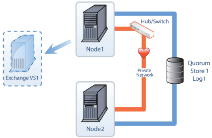
The private network is used by the cluster service so the nodes can talk to each other and verify that each other are up and running.
The process of verification uses two processes called the looksalive resource check and the isalive resource check. If the resources in the cluster fail to respond to the resource checks after the appropriate amount of time, the passive node will assume that the active node has failed and will start up the service or application that is running on the cluster in the virtual server. Some nodes will also have a third network adapter dedicated to the iSCSI network to access the iSCSI SAN. If an iSCSI SAN is used, each node will connect to the SAN through a dedicated network adapter to a private network that the iSCSI SAN also uses.
Each of the nodes is also connected to the shared storage media. In fact, the storage is not shared, but it is accessible to each of the nodes. Only the active node accesses the storage, and the passive node is locked out of the storage by the cluster service. In the figure here, there are three Logical Unit Numbers, or LUNs, that are being provided by the SAN. The nodes will connect to the SAN using fiber channel or iSCSI.
What is a Virtual Server?
One way to define a virtual server is to take a basic application or service and break it down into its components. For example, a file server needs several resources in order to exist. A file server needs:
• A computer to connect to the network
• A TCP/IP address to identify the server and make it accessible to other computers running TCP/IP
• A name to make it easy to identify the computer
• A disk to store data such as the files in a file server
• A service such as the file server service that enables the server to share files out to other computers
In the case of a virtual server, it needs a TCP/IP address, a name, a disk, and a service or application just like a real server. In the case of a cluster, the virtual server uses resources, too. In clustering, the resources have formal names.
For example, there is a Network Name which is the name of the virtual server, an IP Address which is the TCP/IP address of the virtual server, a Physical Disk which resides on the shared storage and holds the data for the service or application, and a Service or Application that is installed on each node in the cluster but only runs on the active node. These resources are grouped together into virtual servers. Users will connect to the virtual server name for the resources they need.
In a cluster, there may be multiple virtual servers. The key to clustering is that if an active node fails, the passive node takes control of the IP Address, Network Name, Physical Disk, and the Service or Application and starts running the service or application. The active node runs the service or application, and the same service or application does not run on the passive nodes. In the event of a failure, the service or application stops functioning on the active node and the passive node detects the failure and starts running the service or application. Users still connect to the same name that they used before and are able to continue running the application.
Why Would I Use Clustering?
There are two major benefits of running services and applications on a cluster. The first reason is to increase availability of a service or application, and the second reason is to reduce the downtime caused by maintenance.
Increasing uptime and availability of a service or application should always be a goal of an information technology department. By having the cluster service monitoring the service or application, any failures can be quickly identified and the service or application can be moved to another node in the cluster within moments. In many cases, a failing service or application can be restarted on a surviving node in the cluster so quickly that nobody will even notice that it failed. Workers can continue accessing the service or application and will not have to call the help desk to notify the information technology department that it failed. Not only will they not have to make those phone calls, they will be able to do their jobs without having to wait for the service or application to be reviewed by the information technology department and then wait for it to be fixed. In other words, it leads to increased productivity.
Software and hardware maintenance time can be reduced considerably in a cluster. Patching and upgrading services and applications on a cluster is much easier in most cases. In a cluster, software and hardware maintenance can be done after being tested in a test environment. Maintenance can be done on a passive node without impacting the services and applications running on the cluster. The active node can continue to run during the maintenance of the passive node.
If maintenance is also required on the active node, it is a simple matter to schedule the work for slow times and move the service or application to the passive node making it the active node. If, for some reason, the service or application fails, it is a simple matter to move it back to its original node, and then troubleshoot any problems that may have come up without having the clustered service or application unavailable.
If there are no problems with the maintenance work, then the other node can be upgraded/fixed as well. This process also works with simple operating system patches and service packs. The down time associated with simple maintenance is reduced considerably and the risk associated with such changes is also reduced.
Prerequisites
For a cluster to be properly supported, and functional, there are several prerequisites that are required as well as a few that are recommended to improve performance and stability. This section will cover the steps that should be performed before configuring the cluster.
Software
The proper operating system is the first requirement. Windows Server 2003 requires either:
• Windows Server 2003 Enterprise Edition
• Windows Server 2003 Enterprise Edition R2
• Windows Server 2003 Datacenter Edition
• Windows Server 2003 Datacenter Edition R2
Windows Server 2008 requires:
• Windows Server 2008 Enterprise Edition
• Windows Server 2008 Datacenter Edition
Both Windows Server 2003 and Windows Server 2008 support 32-bit and 64-bit versions of the above operating systems, however, mixing 32-bit and 64-bit in the same cluster is not supported, and mixing the operating systems between Windows Server 2003 and Windows Server 2008 is not supported, either.
Windows Server 2008 failover clusters have an additional prerequisite that includes installing Windows Powershell. This prerequisite can be installed through the GUI or through the command line. For command line, run ServerManagerCMD -i PowerShell from a command prompt.
Cluster Aware Services and Applications
Many services and applications are cluster aware. What makes a service or application cluster aware is that it has been written to use the APIs provided by the cluster service. Cluster aware services and applications are used to leverage the cluster service and to provide high availability to a service or application. Cluster aware versions of applications often require special editions of the software. Some well known and often clustered services and applications include the following:
• File Services
• Print Ser vices
• DHCP – Dynamic Host Configuration Protocol
• WINS – Windows Internet Naming Service
• DFS – Only standalone DFS can be deployed on a server cluster, and domain roots for DFS are not supported
• Microsoft Exchange
• Microsoft SQL
• Lotus Domino
• IBM DB2
• SAP
• PeopleSoft
• JD Edwards
This list is far from being all inclusive. There are many line of business, internally developed, and third party products on the market that are cluster aware.
The main value in a cluster aware service or application is that the cluster service is able to monitor the health of the resources in the cluster group or virtual server. In the event a resource fails the health checking by the cluster service, the cluster service will failover the service or application to another node in the cluster and start up the service or application within seconds in many cases and within a couple of minutes in others. The time required to failover is based on the type and size of the service or application.
Cluster Unaware Services and Applications
There are many services and applications that are not cluster aware. These services and applications do not leverage the functionality of all of the clustering APIs. For example, these applications do not use a “Looks Alive” and “is Alive” check for the application. In cluster aware applications, the resource checks can test and monitor the health of the resources for the service or application and then cause it to failover in the event of a problem with the application. This is not possible with a cluster unaware application.
However, despite not being able to use all of the features of clustering, cluster unaware applications can be run in clusters along with other critical resources. In order to use these cluster unaware applications, we must use generic resources. While a cluster will not protect the service or application resources, clustering will protect the service or application from a complete server node failure. If the node fails, even a cluster unaware application can be started on a surviving node in the cluster.
Service Installation
The cluster service is automatically installed on Windows Server 2003 Enterprise and Datacenter versions. Server clustering needs to be configured for Windows Server 2003, however, even though it is installed.
In Windows Server 2008, the Failover Cluster feature must be installed on all nodes before they can be added to a cluster. Adding the Failover Cluster feature is just like adding any other feature for Windows Server 2008. Once the feature is added, then it can be configured and service and applications can be added afterwards.
Network
Each node of the cluster is connected to at least two different networks for clustering purposes. Each node is connected to the public network which is where clients can connect to the cluster nodes and attach to applications and services running on the cluster as if the virtual servers were normal servers. The second network is the private network, also referred to as the heartbeat network.
This network is used to connect all nodes of the cluster together so they can keep track of the availability of the nodes in the cluster. It is through this heartbeat network that a passive server node can detect if the active server node has failed and then can take action to start the virtual servers on it.
DNS Tab – In the “Internet Protocol TCI/IP” properties and in the advanced properties on the DNS tab, unselect “Register this connection’s addresses in DNS”
NetBIOS – In the “Internet Protocol TCI/IP” properties and in the advanced properties on the WINS tab select the radio button for “Disable NetBIOS over TCP/IP”
Services – remove the “Client for Microsoft Networks” and the “File and Printer Sharing for Microsoft Networks” on the General tab for the connection properties.
It is possible that other networks also are used for such things as dedicated backups or for iSCSI connections, but they are not used for cluster purposes.
Private Network Configuration – Proper configuration of the private network will remove unneeded services and help the network function in a nice and simple configuration; which is all that is needed.
The heartbeat network is a private network shared just by the nodes of a cluster and should not be accessible to any other systems including other clusters. It is not supposed to be routable at all. Make sure that you use private IP addresses per RFC 1918 for your heartbeat network that do not exist anywhere else in your network.
The recommended ranges, per RFC 1918, include:
• 10.0.0.0 – 10.255.255.255 (10/8)
• 172.16.0.0 – 172.31.255.255 (172.16/12)
• 192.168.0.0 – 192.168.255.255 (192.168/16)
Speed and Duplex – Always configure the network adapters manually to force the setting for best performance. Leaving the NIC set to the default of “Auto Detect” can result in improper configuration settings. If the NIC is 100 MB and Full Duplex and the switch supports it, then force the setting to 100 Full.
Network Priority – A common problem with the configuration of the network settings is that the network priority is not configured properly. The priority can be configured for the networks in the advanced properties for the network connections. The public network should be first in the binding order because it is the one that is most used and it is the one that will have the most impact on user access to the cluster. The private network is not going to have anywhere near the network traffic of the public network.
Storage
The shared disk environment for clustering is vital to the cluster working properly. The quorum (known as a witness disk in Windows Server 2008) is maintained on one of these disks and it should have its own separate disk of at least 512 MB and formatted using NTFS. All disks presented by the shared storage environment must have the same drive letter associated with them on all nodes. So, the quorum must have the same drive letter on all nodes in the cluster, for example.
Cluster Disks
The disks used in clustering should not be confused with the disks used by the nodes to host the operating system and to host binaries for clustered applications. It is important to note that no matter what the source is of the shared disks, they must be formatted using NTFS and they must be presented to Windows as basic disks. In many SAN environments, the control of which servers can access the disks is handled by the SAN environment. Cluster disks are used by applications that need a place to store their data such as Exchange Server and SQL Server.
Shared – The disk environment must be visible and accessible by all nodes in the cluster. While only one node can access individual disks at a time, the disks must be able to be transferred to another node in the event of a failure. While the disks are not truly shared, they can be mounted and accessed from the nodes in the cluster.
SAN – Storage area networks (SANs) typically use storage-specific network technologies. Servers connect to the storage and access data at the block level usually using a host bus adapter (HBA). Disks available via the HBA are treated just like disks attached directly. In other words, SAN disks are accessed using the same read and write disk processes used for locally attached disks. SANs can use fiber channel or iSCSI technology.
SANs are the preferred method of providing disks to the cluster nodes. A SAN is able to provide a large amount of space and divide it up in several smaller pieces as needed for each application. For example, two physical disks (and it can be parts of disks in the SAN in most cases) are combined in a RAID 1 set to create the Quorum disk, two disks are combined in a RAID 1 set to create a Log disk, and three disks are combined in a RAID 5 set to create the Data disk. Each of these three LUNs are seen by the nodes as physical disks. So, the nodes see three disks; one intended to be used for the quorum, one intended to be used for the logs, and one intended to be used for the data drive. The sizes, number of physical disks used, and the RAID type can vary for performance reasons and are also subject the capabilities of the SAN.
NAS – Generally, Network Attached Storage (NAS) devices are not supported for server clustering. Several third parties, though, create drivers that allow their NAS drives to be used for clustering, but they are the ones that end up having to provide support in the event there are any problems. NAS does not use block level access like a SAN does. However, drivers can be used to make the file share access used by NAS to make it look and act like block level access in a SAN.
iSCSI – iSCSI is a newer technology that is supported for server clustering starting with Windows Server 2003 Service Pack 1 and is fully supported for failover clustering in Windows Server 2008. With iSCSI, a node is able to connect to the shared storage on the iSCSI server using iSCSI initiators (the client side) connecting to iSCSI targets (the storage side where a server runs the target software and exposes the disks) across standard Ethernet connections. GigE is preferred for higher performance, and 10GigE is now becoming more available.
Microsoft supplies its own iSCSI initiator, and we recommend using it because they support up to 8 node clusters using their initiator. Microsoft, at this time, does not provide an iSCSI target except through Windows Server Storage Edition that is only available through original equipment manufacturers. It is recommended that if iSCSI is being used that a dedicated network be used for all storage traffic to get the best performance from the storage device.
In the case of iSCSI, there will be at least three network adapters for each node; one NIC for the public network, one NIC for the private (heartbeat) network, and one NIC for the iSCSI traffic supporting the storage device.
Storage virtualization software that converts industry-standard servers into iSCSI SANs provides a reliable, flexible and costeffective shared storage that can be centrally managed. iSCSI technology is scalable enough to meet the needs of many large enterprises yet, at the same time, it is also cost-effective for the SMB market. For example, StarWind Software, provides enterprise-level features like volume based snapshots, fault tolerant storage via its network-based RAID1 mirror functionality and remote, asynchronous replication. This set of features, combined with the solid foundation of a 4th generation product, makes StarWind Software an ideal choice for server applications such as Microsoft Server Clustering and Failover Clustering.
StarWind Software also provides a cost effective platform for Hyper-V and Live Migration as well as Windows server clustering for database applications such as Microsoft SQL Server, Microsoft Exchange and Microsoft SharePoint Server.
LUNs – Logical Unit Numbers are used to identify disk slices from a storage device that are then presented to client computers. A LUN is the logical device provided by the storage device and it is then treated as a physical device by the node that is allowed to view and connect to the LUN.
Quorum
In Windows Server 2003, there are three options for the quorum:
1. Local Quorum – This option is used for creation of a single node cluster and does not support the addition of other nodes. A single node cluster is often used in development and testing environments to make sure that applications can run on a cluster without any problems.
2. Quorum Disk – In the large majority of Windows Server 2003 server clusters, a disk is used that resides on the shared storage environment and it is configured so it is available to all the nodes in the cluster.
3. Majority Node Set (MNS) – In MNS, quorum information is stored on the operating system drive of the individual nodes. MNS can be used in clusters with three or more nodes so that the cluster will continue to run in the event of a node failure. Using MNS with two nodes in a cluster will not provide protection against the failure of a node. In a two node cluster using MNS, if there is a node failure, the quorum cannot be established and the cluster service will fail to start or will fail if it is running before the failure of a node.
In Windows Server 2008, there are four options for the quorum:
1. Node majority – Node majority is very much like MNS in Windows Server 2003. In this option, a vote is given to each node of the cluster and the cluster will continue to run so long as there are a majority of nodes up and running.
This option is recommended when there is an odd number of nodes in the cluster.
2. Nodes and Disk Majority – This is a common configuration for two node clusters. Each node gets a vote and the quorum disk (now called a witness disk) also gets a vote. So long as two of the three are running, the cluster will continue. In this situation, the cluster can actually lose the witness disk and still run. This option is recommended for clusters with an even number of nodes.
3. Node and File Share Majority – This option uses the MNS model with a file share witness. In this option, each node gets a vote and another vote is given to a file share on another server that hosts quorum information. The file share also gets a vote. This is the same as the second option, but it uses a file share witness instead of a witness disk.
4. No Majority: Disk Only – This option equates to the well known, tried, and true model that has been used for years. A single vote is assigned to the witness disk. In this option, so long as at least one node is available and the disk is available, then the cluster will continue to run. This solution is not recommended because the disk becomes a single point of failure.
A quorum is required for both Windows Server 2003 server clusters and in Windows Server 2008 failover clusters. In cases where a quorum disk (witness disk in Windows Server 2008) is used, it must be formatted using NTFS, it must be a basic disk (dynamic disks are not supported by the operating system for clustering), and it should be over 512 MB in size after formatting. The size requirement is based on NTFS formatting. NTFS is more efficient for disks larger than 500 MB. The size is solely based on NTFS performance and the cluster logs hosted on the quorum drive will not come close to consuming the disk space.
Accounts
Each node must have a computer account, making it part of a domain. Administrators must use a user account that has administrator permissions on each of the nodes, but it does not need to be a domain administrator account. In Windows Server 2003 server clusters, this account is also used as a service account for the cluster service. In Windows Server 2008 failover clusters, a service account is not required for the cluster service. However, the account used when creating a failover cluster must have the permission to Create Computer Objects in the domain. In failover clusters, the cluster service runs in a special security context.
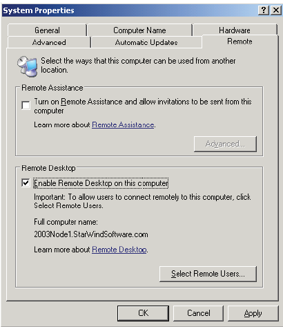
Remote Administration
On the Remote tab for System Properties, enable the check box to Enable Remote Desktop on this computer. By default, only local administrators will be able to log on using remote desktop. Do not enable the check box to Turn on Remote Assistance and allow invitations to be sent from this computer. The Terminal Services Configuration should be changed to improve security by turning off the ability to be shadowed by another administrator and having the RDP session taken over. Click on Start, All Programs, Administrative Tools, and Terminal Services Configuration to open the console. In the console, right click on RDP-Tcp in the right hand pane and select Properties. On the Remote Control tab, select the radio button for Do not allow remote control. This will disable the ability of other administrators to shadow your RDP sessions.
Operating System Configuration Changes
A few changes should be made to the operating system configuration to provide a more stable cluster. Each node should be configured to:
Disable Automatic Updates – One of the key reasons for deploying a cluster is to keep it up and running. Automatic Updates has the potential to download updates and restart the nodes in a cluster based on the patch or service pack that it might download. It is vital that administrators control when patches are applied and that all patches are tested properly in a test environment before being applied to the nodes in a cluster.
Set Virtual Memory Settings – The virtual memory settings should be configured so that the operating system does not control the sizing and so that the sizing does not change between a minimum and maximum size. Allowing the virtual memory (swap file) to change its size can result in fragmentation of the swap file. All swap files should be configured so that minimum and maximum sizes are set the same. It is also important to note that if the swap file is moved to a disk other than the disk hosting the operating system, dump files cannot be captured. The maximum size of a swap file is 4095. See KB 237740 for information on how to use more disk space for the swap file beyond the maximum of 4095 shown here: http:// support.microsoft.com/kb/237740.
Change the Startup and Recovery Settings – The time that the startup menu is displayed should be configured differently between the nodes in a cluster. If the time is the same, and there is a major outage, then it is possible for all nodes to startup at the same time and to conflict with each other when trying to start the cluster service. If the times are set differently, then one node will start before the remaining nodes and it will be able to start the cluster service without any conflicts. As the remaining nodes come online, they will be able to join the cluster without incident.
Install Backinfo – The BackInfo application will display computer information on the screen so that it is clear which computer is being used when connecting to a cluster. This application makes it very easy to get key information about a server within moments of logging onto the server.
Install Security Configuration Wizard – The Security Configuration Wizard (SCW) is a fantastic tool that enables administrators to lock down computers. The SCW can be used to turn off unnecessary services and to configure the Windows firewall to block unnecessary ports. Proper use of the SCW will reduce the attack surface of the nodes in the cluster.
Pre-configuration Analysis – Cluster Configuration Validation Wizard (ClusPrep) vs. Validate
It makes absolutely no sense to try to establish a cluster without first verifying that the hardware and software configuration can properly support clustering.
ClusPrep
Microsoft released the Cluster Configuration Validation Wizard to help identify any configuration errors before installing server clustering in Windows Server 2003. While the ClusPrep tool does not guarantee support from Microsoft, it does help identify any major problems with the configuration before configuring server clustering or as a troubleshooting tool after server clustering is configured and the nodes are part of a server cluster. The ClusPrep tool runs tests will validate that the computers are properly configured by running inventory tests that report problems with service pack levels, driver versions, and other differences between the hardware and software on the computers as well as testing the network and storage configurations. The resulting report will clearly identify differences between the computers that should be addressed.
ClusPrep must be run on an x86 based computer, however, it will properly test the configurations of x64 and Itanium computers as well. ClusPrep also cannot be run from a Vista or Windows Server 2008 operating system.
ClusPrep should be run before the computers are joined to a server cluster so that ClusPrep can properly test the storage configuration. Once the computers have been joined to a server cluster, ClusPrep will not test the storage configuration since its tests may disrupt a server cluster that is in production.
Validate
The Validate tool is available in Windows Server 2008 and is based on the ClusPrep tool. However, one very big difference exists between ClusPrep and Validate. In failover clustering, if the cluster nodes pass the validate tool, the cluster will be fully supported by Microsoft.
The validate tool will run through the following checks on each node and on the cluster configuration where possible. Depending on the number of nodes, it can take thirty minutes or more. In most cases it will take between five and fifteen minutes.
Inventory
• List BIOS information
• List Environment Variables
• List Fiber Channel Host Bus Adapters
• List Memory Information
• List Operating System Information
• List Plug and Play Devices
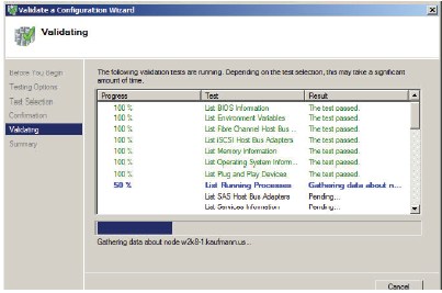
• List Running Processes
• List SAS Host Bus Adapters
• List Services Information
• List Software Updates
• List System Drivers
• List System Information
• List Unsigned Drivers
Network
• Validate Cluster Network Configuration
• Validate IP Configuration
• Validate Network Communication
• Validate Windows Firewall Configuration
Storage
• List All Disks
• List Potential Cluster Disks
• Validate Disk Access Latency
• Validate Disk Arbitration
• Validate Disk Failover
• Validate File System
• Validate Microsoft MPIO-Based Disks
• Validate Multiple Arbitration
• Validate SCSI Device Vital Product Data (VPD)
• Validate SCSI-3 Persistent Reservation
• Validate Simultaneous Failover
System Configuration
• Validate Active Directory Configuration
• Validate All Drivers Signed
• Validate Operating System Versions
• Validate Required Services
• Validate Same Processor Architecture
• Validate Software Update Levels
Like ClusPrep, Validate will generate a report identifying any issues with the computers that should be addressed before configuring failover clusters in Windows Server 2008.
Setup iSCSI Target
One of the first steps after installing and updating the servers is to configure the iSCSI target. This step is pretty easy when using StarWind Software. The basics steps are shown here, however, remember to go to www.starwindsoftware.com for more information about the configuration options available.
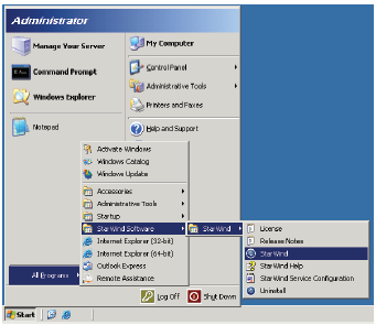
1. After installing StarWind Software’s iSCSI target software, open the management console by clicking Start, All Programs, StarWind Software, StarWind, StarWind.
2. Right-click localhost:3260 and select Properties from the context menu, and click Connect.
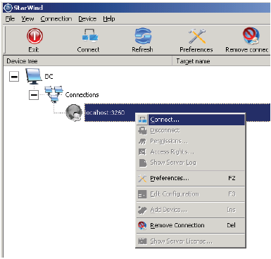
3. For the out of the box installation, the User name field will have test entered. Also enter test for the Password field and click OK.
4. Right-click localhost:3260 again, and select Add Device.
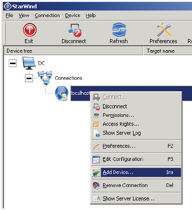
5. Select Image File device from the options and click Next.
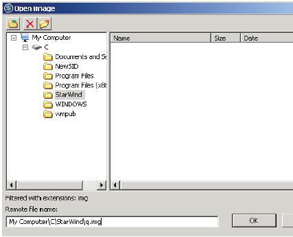
6. Select Create new virtual disk and click Next.
7. Select the ellipses and navigate to the hard drive and folder to store the image file and fill in a name of q.img, and click Next.
8. Enter 512 for the Size in MBs field and click Next.
9. Enable the Allow multiple concurrent iSCSI connections (clustering) check box, and click Next.
10. Type Quorum in the Choose a target name (optional): field, and click Next.
11. Click Next in the Completing the Add Device Wizard window, and click Finish to complete creating an iSCSI disk on the iSCSI target server.
12. Repeat steps 4-11 and create another disk with s.img and Storage for the name requirements.
Setup iSCSI Initiator
Windows Server 2008 has an iSCSI initiator built-in and it only requires being configured to connect to the iSCSI target. Windows Server 2003, however, needs to have an iSCSI initiator installed and configured.
Go to http://www.microsoft.com/downloads and search for an iSCSI initiator to download and install on Windows Server 2003 servers.
The steps for configuring the iSCSI initiator need to be performed on all servers that will be nodes in the cluster.
Windows Server 2003 Steps
1. Click Start, All Programs, Microsoft iSCSI Initiator, Microsoft iSCSI Initiator.
2. Click on the Discovery Tab and click on the Add button for the Target Portals section.
3. Enter the IP address of the iSCSI target and click OK.
4. Click on the Targets tab, click on the Quorum target name, and click on Log On.
5. Enable the check box for Automatically restore this connection with the system boots, and click OK.
6. Click on the Targets tab, click on the Storage target name, and click on Log On.
7. Enable the check box for Automatically restore this connection with the system boots, and click OK.
8. Click OK again to close the iSCSI Initiator Properties window.
Windows Server 2008 Steps
1. Click Start, Control Panel, iSCSI Initiator. Click Yes if prompted to start the iSCSI service. Click Yes if prompted to unblock the Microsoft iSCSI service for Windows Firewall.
2. Click on the Discovery Tab and click on the Add Portal button for the Target Portals section.
3. Enter the IP address of the iSCSI target and click OK.
4. Click on the Targets tab, click on the Quorum target name, and click on Log on.
5. Enable the check box for Automatically restore this connection with the system boots, and click OK.
6. Click on the Targets tab, click on the Storage target name, and click on Log on.
7. Enable the check box for Automatically restore this connection with the system boots, and click OK.
8. Click OK again to close the iSCSI Initiator Properties window.
Partition and Format the Cluster Disks
Only perform the steps below for one of the servers that will be a node in the cluster and then use that node to start the cluster configuration.
Open the Disk Manager by clicking Start, Administrative Tools, Computer Management.
1. In Computer Management, expand the Storage object and then click on Disk Management.
2. Initialize all disks when prompted.
3. Do NOT convert the disks to Dynamic disks when prompted. All Server Cluster disks must be basic disks.
4. Use the Disk Management tool and partition and format all cluster disks using NTFS.
Note : It is considered a best practice to use the letter Q for the quorum disk.
Step by Step Installation for Windows Server 2003
After installing the operating system, setting up the network adapters, and configuring the shared storage environment, server clustering can be configured using the following steps:
1. Verify TCP/IP connectivity between the nodes through the public network interface and the private network interface by running ping from a command prompt.
2. Verify TCP/IP connectivity between the nodes and the domain controllers and the DNS servers through the public network interface by running ping from a command prompt.
3. If using iSCSI, verify TCP/IP connectivity between the iSCSI network interface and the iSCSI target by running ping from a command prompt.
4. Log onto one of the computers that will be a node in the cluster as a local administrator on the node.
5. Launch Cluster Administrator from Start, All Programs, Administrative Tools, and then Cluster Administrator.
6. On the Open Connection to Cluster dialog box choose the Create new cluster and click OK.
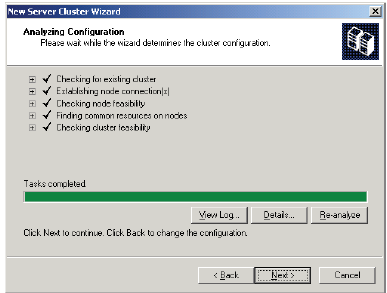
7. On the Welcome to the New Server Cluster Wizard page click Next.
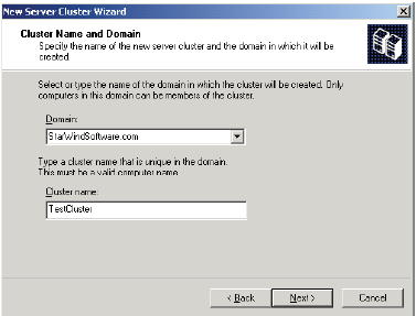
8. On the Cluster Name and Domain page type ClusterName (the name of the cluster that will be used to identify and administer the cluster in the future) for the Cluster name and click Next.
9. On the Select Computer page click Next.
10. On the Analyzing Configuration page click Next. If the quorum disk is not at least 500 MB after formatting, the Finding common resource on nodes warning will state that the best practices for the Quorum are not being followed.
11. On the IP Address page type the IP address for the cluster that will be used to identify and administer the cluster and then click Next.
12. On the Cluster Service Account page type in the service account that will be used for the server cluster and the password in for the User name and for the Password fields and then click Next.
Note : the cluster service account has to be a local administrator on all nodes of the cluster and it has to be a domain user account. The account does NOT have to be a domain administrator.
13. On the Proposed Cluster Configuration page click Next.
14. On the Creating the Cluster page, click Next.
15. On the Completing the New Server Cluster Wizard page click Finish.
Note : At this point, you have a single node cluster.
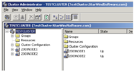
16. Leave the first node running and the Cluster Administrator console open.
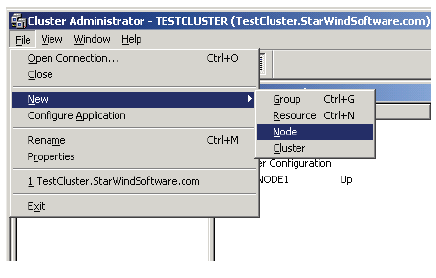
17. In Cluster Administrator, click on File, New, and Node.
18. On the Welcome to the Add Nodes Wizard page click Next.
19. On the Select Computer page, enter the name of the second node in the Computer name field, click Add then click Next.
20. On the Analyzing Configuration page click Next.
21. On the Cluster Service Account page type in the password for the service account for the Password and then click Next.
22. On the Proposed Cluster Configuration page click Next.
23. On the Adding Nodes to the Cluster page click Next.
24. On the Completing the Add Nodes Wizard page click Finish.
25. Repeat steps 16-24 for any additional servers that will be nodes in the server cluster.
26. Check the System Event Log for any errors and correct them as needed.
Step by Step Installation for Windows Server 2008
Failover clustering can be installed using the after installing the operating system, setting up the network adapters, installing the prerequisite features and roles discussed in the prerequisites section of this document which includes installing the failover cluster feature, and configuring the shared storage environment.
The actual steps of creating the failover cluster are incredibly simple in comparison to configuring a server cluster in Windows Server 2003. At a high level, the steps include installing the proper software prerequisites, and then using the Failover Cluster console to create the cluster. The detailed steps include:
1. Verify TCP/IP connectivity between the nodes through the public network interface and the private network interface by running ping from a command prompt.
2. Verify TCP/IP connectivity between the nodes and the domain controllers and the DNS servers through the public network interface by running ping from a command prompt.
3. If using iSCSI, verify TCP/IP connectivity between the iSCSI network interface and the iSCSI target by running ping from a command prompt.
4. Log onto one of the computers that will be a node in the cluster as a local administrator on the node.
5. Launch Server Manager from Start, Administrative Tools, and then Server Manager. If the User Account Control dialog box appears, click Continue.
6. In Server Manager, under Features Summary, click on Add Features. You may need to scroll down in the Server Manager console to find the Features Summary.
7. In the Add Features Wizard, click on Failover Clustering and then click Next then Install. Click Close when the feature is finished installing.
8. Repeat steps 4-7 for all other servers that will be nodes in the cluster.
9. Complete the steps of the wizard to finish installing the Failover Clustering feature.
Note : As an alternative to steps 5-7, run ServerManagerCMD -i Failover-Clustering from a command prompt.
10. Repeat steps 7 and 8 on all servers that will be nodes in the failover cluster.
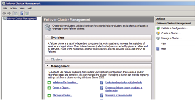
11. Open the Failover Cluster Management console by clicking on Start, Administrative Tools, and Failover Cluster Management. Click Continue if the User Account Control dialog box appears.
12. In the Failover Cluster Management console, click on Validate a Configuration to run the Validate a Configuration Wizard.
13. Follow the steps of the wizard and add all nodes for the validation tests and complete the steps of the Validate a Configuration Wizard.
14. In the Summary page of the Validate a Configuration Wizard, click on the View Report link and verify that there are no failures. If there are failures, address the problems reported and then re-run the wizard.
15. In the Failover Cluster Management console, click on the Create a Cluster link.
16. Click Next in the Before You Begin page of the Create Cluster Wizard.
17. Click Browse in the Select Servers page, and then enter the names of the servers that will be nodes in the cluster in the Enter the object names to select (examples) field, and click the Check Names button. Repeat as needed to enter all the server names in the field, and click Next.
18. Select the radio button to perform the validation tests and click Next.
19. Click Next on the Before You Begin page for the Validate a Configuration Wizard.
20. Select the radio button to run all of the validation test and click Next.
21. Click Next on the Confirmation page.
22. Correct any errors and re-run the validation process as needed. Click Finish when the wizard runs without errors.
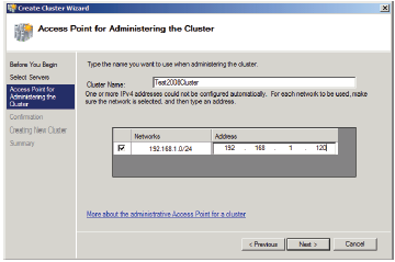
23. Enter the cluster name in the Cluster Name field and then enter the IP address for the Access Point for Administering the Cluster page. Click Next.
24. Click Next on the Confirmation page.
25. After the wizard completes, click on View Report in the Summary page. Click Finish and close any open windows.
26. Check the System Event Log for any errors and correct them as needed.
Clustering of Windows Server 2003 vs . Windows Server 2008
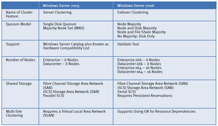
Clustering changed considerably between the Windows Server 2003 release and the Windows Server 2008 release. Several of the changes are listed below.
Name of Cluster Feature
Microsoft likes to change the names of features and roles depending on the version of the operation system, especially when there is a significant change in the functionality. In the case of Windows Server 2008, Microsoft made the distinction between roles and features more distinct and they also changed the name of the feature for clustering to Failover Clustering. This change makes it easier to distinguish the version being deployed when talking about a cluster.
Support
In Windows Server 2003 Server Clustering, a complete solution must be purchased from the Windows Server Catalog, http://www.windowsservercatalog.com. A complete solution
includes:
• Server Nodes
• Network Adapter (usually part of the server)
• Operating System
• Storage
• Host Bus Adapter
• Storage Switch
In Windows Server 2003, it is vital that a complete solution is purchased to get full support from Microsoft. However, it has been clear for many years that most organizations did not follow this requirement. Microsoft support for Windows Server 2003 server clustering would only be provided in a best effort scenario if the entire solution was not certified. In Windows Server 2008 Failover Clustering, purchasing a complete solution is no longer required, although each component does need to come with the Windows 2008 logo for complete support.
The validate tool enables administrators to test the hardware components after the cluster hardware has been installed. The validate tool will confirm whether a set of components will work properly with failover clustering. If a solution passes the validate tool without errors or warnings, it will be supported by Microsoft.
Since many organizations do not want to take the risk of purchasing hardware without knowing that it will pass validate, Microsoft works with hardware vendors to provide pre configured hardware solutions that are guaranteed to pass the validate step.
The Microsoft Failover Cluster Configuration Program (FCCP) provides a list of partners that have configurations that will pass validate. For more information, visit:http://www.microsoft.com/windowsserver2008/en/us/failover-clusteringprogram-overview.aspx.
Number of Nodes
The change from x86 (32-bit) to x64 (64-bit) allows for more nodes to be supported in a Failover Cluster. In Windows Server 2003, the maximum number of nodes is 8 nodes per cluster. In Windows Server 2008, the number of supported nodes increased to 16 nodes when using x64 nodes. All nodes must be the same architecture which means it is not possible to have a failover cluster with both x86 and x64 based computers. Failover clusters running Itanium based nodes can only have up to 8 nodes per cluster.
Shared Storage
The biggest change is generally considered to be the storage requirement. For applications that require shared storage, Microsoft made a significant change in the storage. The storage requires support for persistent reservations, a feature of SCSI-3 that was not required in Windows Server 2003. Some of the changes from Windows Server 2003 to Windows Server 2008 include the following:
• 2TB Limit- Windows Server 2003 requires a hot fix to support GUID Partition Tables (GPT) instead of Master Boot Records (MBR) for disk partitioning. Windows Server 2008 fully supports GPT. MBR is limited to two terabyte. GPT changes the limit to sixteen Exabyte. Of course, the GPT limit is completely theoretical at this point. The practical limit is really around 160-200 TB based on today’s technology. It is important to note that large disk sizes are troublesome whether being used in a cluster or on single servers. For example, defragmenting or running check disk against a large partition can result in significant downtime for the resource.
• SCSI Bus Resets – In Windows Server 2003 Server Clustering, SCSI bus resets are used to break disk reservations forcing disks to disconnect so that the disks can be controlled by another node. SCSI bus resets require all disks on the same bus to disconnect. In Windows Server 2008 Failover Clustering, SCSI bus resets are not used and persistent reservations are now required.
• Persistent Reservations – Windows Server 2008 Failover Clustering supports the use of persistent reservations. Parallel SCSI storage is not supported in 2008 for Failover Clustering because it is not able to support persistent reservations. Serially Attached Storage (SAS), Fiber Channel, and iSCSI are supported for Windows Server 2008.
• Maintenance Mode – Maintenance mode allows administrators to gain exclusive control of shared disks. Maintenance mode is also supported in Windows Server 2003, but it has been improved in Windows Server 2008 and is often being used to support snap shot backups.
• Disk Signatures – In Windows Server 2003, server clustering uses disk signatures to identify each clustered disk. The disk signature, at sector 0, is often an issue in disaster recovery scenarios. Windows Server 2008 Failover Clustering uses SCSI Inquiry Data written to a LUN by a SAN. In the event of a problem with the disk signature, the disk signature can be reset once the disk has been verified by the SCSI Inquiry Data. If for some reason, both the disk signature and the SCSI Inquiry Data are not available, an administrator can use the Repair button on the Physical Disk Resource properties general page.
• Disk Management – The virtual disk service (VDS) APIs first became available with 2003 R2. Using the disk tools in Windows Server 2003 R2 and in Windows Server 2008, an administrator can build, delete, and extend volumes in the SAN.
There have been some pretty significant changes when it comes to the way Windows Server 2008 Failover Clusters work with disk storage in comparison to Windows Server 2003.
Multi-site Clustering
The concept of multi-site clustering has become extremely important to many companies as a means of providing site resiliency.
In Windows Server 2003, virtual local area networks (VLANs) are used to fool the cluster nodes into believing they are on the same network segment. VLANs are cumbersome to support and require network layer support to maintain multi-site clusters.
In Windows Server 2008, IP Address resources can be configured using OR statements so that the cluster nodes can be spread between sites without having to establish VLANs between the locations. The use of OR configurations is a major step towards easier configuration for multi-site LANs.
While the OR capability applies to all resources, it major benefit comes from using it with IP Address resources. In a multisite clusters, an administrator can create IP Address resources for both sites. With the AND, if one IP address resource fails, then the cluster group will fail. With the OR capability you can configure the dependency for the network name to include the IP for one site OR the IP for the second site. If either IP is functional, then the resource will function using that IP address for the site that is functional.
Summary
Microsoft Windows Server 2003 and Microsoft Windows Server 2008 can be used to provide a highly available platform for many services and applications. The requirements include:
• The appropriate Windows Server version
• At least two network adapters
• A shared storage environment
• A domain to manage and host the user and computer accounts required for clustering
While Windows Server 2003 is still being used to support server clusters, the advances in Windows Server 2008 failover clustering are considerable in multiple ways, including:
• Reduced administrative overhead to configure
• Reduced administrative overhead to maintain
• Less expensive hardware requirements
• More flexible hardware requirements
Windows Server clustering meets the needs of IT and also meets the needs of business managers despite the changes in the economy that are forcing businesses to do more with less and still maintain the stability of applications.
How do I Add an ISCSI Target to Windows?
Launch the iSCSI initiator at Control Panel > Tools.
On the iSCSI Initiator Properties page, click Discovery.
Enter the IP address of the NAS and then click OK.
Click Targets and then select the available iSCSI targets that you want to connect.
Click Connect.
Click OK.
How do I Set up an ISCSI Target?
Step 1: Open Server Manager.
Step 2: RoleBased or Featurebased installation.
Step 3: Choose Server.
Step 4: Select Server Roles.
Step 5: Add Features.
Step 6: Confirm Selections.
Step 7: Configure iSCSI Target Folder.
Step 8: Choose the folder we created.
How do I Find ISCSI Target in Windows?
The first step in establishing connectivity to the iSCSI target is to go to the Targets tab on the iSCSI Initiator Properties sheet, then enter the IP address of your intended iSCSI target. Click the Quick Connect button, and the iSCSI Initiator should discover your iSCSI target.
How do I Install ISCSI Storage?
On the Windows machine, search for and launch iSCSI Initiator.
In iSCSI Initiator, enter the IP address of the Datto appliance or offsite server hosting the share into the Target field.
In the Quick Connect window, click the iSCSI target you want to connect to, Then, click Connect.
How to Add ISCSI Storage to Windows Server, Using a ISCSI …
На чтение 3 мин Опубликовано Обновлено
Содержание
- Введение
- Шаг 1: Установка программы iSCSI Initiator
- Шаг 2: Настройка iSCSI Initiator
- Шаг 3: Подключение к удаленному диску
- Заключение
- Установка и настройка iSCSI инициатора в операционной системе Windows Server 2003
Введение
Инициатор iSCSI — программное обеспечение для установления соединения и работы с устройствами, подключенными по протоколу iSCSI. В Windows Server 2003 этот функционал предоставляется встроенным средством iSCSI Initiator. Данная инструкция поможет наладить работу и настроить iSCSI Initiator в Windows Server 2003.
Шаг 1: Установка программы iSCSI Initiator
1. Перейдите в «Панель управления» и выберите «Добавление/удаление программ».
2. Нажмите на вкладку «Добавление/удаление компонентов Windows».
3. Откроется мастер установки компонентов Windows. Убедитесь, что у вас есть установочный диск или файлы установки Windows Server 2003.
4. Найдите компонент «iSCSI Initiator» в списке доступных компонентов и отметьте его для установки.
5. Следуйте инструкциям мастера установки для завершения процесса установки iSCSI Initiator.
Шаг 2: Настройка iSCSI Initiator
1. Откройте «Панель управления» и выберите «Администрирование».
2. Выберите «Инициатор iSCSI». Откроется окно «iSCSI Initiator Properties».
3. Вкладка «Targets» содержит список доступных устройств iSCSI. Нажмите «Add» для добавления нового устройства.
4. Введите IP-адрес целевого устройства в поле «Target IP Address».
5. Нажмите «Quick Connect» для установления соединения с устройством.
6. Если соединение установлено успешно, вы увидите список доступных логических устройств. Отметьте нужные и нажмите «OK».
7. Вкладка «Initiator» позволяет настроить параметры инициатора iSCSI. Здесь вы можете изменить имя инициатора, настроить параметры подключения и т.д.
8. Нажмите «OK», чтобы сохранить все настройки.
Шаг 3: Подключение к удаленному диску
1. Перейдите в «Панель управления» и выберите «Система».
2. Вкладка «Управление дисками» показывает список доступных дисков.
3. Найдите подключенный диск iSCSI в списке и установите его активным.
4. Диск будет доступен для работы на сервере.
Заключение
Настройка и использование iSCSI Initiator в Windows Server 2003 позволяет устанавливать соединение с удаленными устройствами iSCSI и работать с ними, как с локальными дисками. Выполнив все указанные шаги, вы сможете настроить и использовать iSCSI Initiator на Windows Server 2003.
Установка и настройка iSCSI инициатора в операционной системе Windows Server 2003
Для установки и настройки iSCSI инициатора в операционной системе Windows Server 2003 следуйте следующим шагам:
- Загрузите компьютер с установочного диска Windows Server 2003 и выберите язык установки.
- Нажмите «Enter» для установки операционной системы.
- Прочтите и согласитесь с лицензионным соглашением, нажав «F8».
- Выберите раздел, на который будет установлена операционная система, и нажмите «Enter».
- Выберите тип установки, например «Типичная», и нажмите «Enter».
- Подождите, пока операционная система будет установлена, и перезагрузитесь.
- После перезагрузки, войдите в систему, используя учетные данные администратора.
- Скачайте и установите драйвер iSCSI инициатора для Windows Server 2003 с официального сайта.
- Запустите установку драйвера и следуйте инструкциям мастера установки.
- После завершения установки, откройте консоль управления и найдите раздел «Сеть».
- Нажмите правой кнопкой мыши на раздел «Сетевые подключения» и выберите «Создать новое подключение».
- Выберите «Мастер настройки подключения к сети» и нажмите «Далее».
- Выберите «Подключение к удаленной сети» и нажмите «Далее».
- Выберите «Соединение с сетью с использованием службы протокола iSCSI» и нажмите «Далее».
- Введите IP-адрес и порт удаленного хранилища данных (iSCSI-цель) и нажмите «Далее».
- Выберите «Использовать указанный идентификатор запроса» и введите имя идентификатора запроса. Нажмите «Далее».
- Выберите «Нужно ли входное подключение» в зависимости от требований и настройте параметры подключения. Нажмите «Далее».
- Повторите предыдущий шаг для выходного подключения, если необходимо.
- Нажмите «Готово», чтобы завершить настройку iSCSI инициатора.
Теперь ваш сервер Windows Server 2003 настроен как iSCSI инициатор и готов к использованию удаленного хранилища данных.
1. Launch Server Manager > Tools > iSCSI Initiator or Control Panel > Administrative Tools > iSCSI Initiator 2. Select Yes to start the Microsoft iSCSI service 3. Re-launch iSCSI initiator, then follow the steps in Windows 2003 section
How does multi-path iSCSI work in a server?
This is achieved by means of the 10 Gigabit trunk between the two switches. This is therefore, two paths to the storage – one source interface, and two target interfaces. Similarly, Port B of the server can talk to Channel 4 of Controller A and Controller B – thus providing 4 channels to the storage.
How to add MPIO to Windows Server iSCSI?
Add and Configure MPIO. 1 Click Manage > Add Roles And Features. 2 Click Next to get to the Features screen. 3 Check the box for Multipath I/O (MPIO). 4 Complete the wizard and wait for the installation to complete.
How to connect to a single target in iSCSI?
Going back to your iSCSI Initiator on your server, select the “Targets” tab. If all has gone well, you should see a single target (i.e. your SAN), and the status is Inactive. Highlight the target, then click on “Connect”.
When to use iSCSI target server in the lab?
Development, test, demonstration, and lab environments When iSCSI Target Server is enabled, a computer running the Windows Server operating system becomes a network-accessible block storage device. This is useful for testing applications prior to deployment in a storage area network (SAN).
How are HBAs and initiators used in SCSI?
A target, like HBAs and initiators, is an end point in SCSI bus communication, passing command descriptor blocks (CDB) to request or provide storage transactions. To provide access to the storage or output device, a target is configured with one or more logical unit numbers (LUNs).
How to list available firewall rules for msiscsiservice?
To list available firewall rules related to the MSiSCSIservice, use the following command: 2. Connecting to available iSCSI Targets: 3. Listing iSCSI Connections and sessions: 4. Listing all Windows disks for a specific iSCSI session: 5. Listing the iSCSI IQN for the iSCSI Initiator
canterbury#show vsan membership
vsan 1 interfaces:
 fc1/3 fc1/10 fc1/12 fc1/13 fc1/14 fc1/16

vsan 222 interfaces:
 fc1/5 fc1/6 fc1/7 fc1/8

vsan 4094(isolated_vsan) interfaces:

canterbury#show zone status
VSAN: 1 default-zone: permit distribute: active only Interop: 100
Full Zoning Database :
 Zonesets:0 Zones:0 Aliases: 0
Active Zoning Database :
 Database Not Available
Status:

VSAN: 222 default-zone: permit distribute: active only Interop: 100
Full Zoning Database :
 Zonesets:0 Zones:0 Aliases: 0
Active Zoning Database :
 Database Not Available
Status:
!--- VSAN 222 has been used for this configuration, default-zone behavior has been set to permit.
canterbury#show flogi database vsan 222
---------------------------------------------------------------------------
INTERFACE VSAN FCID PORT NAME NODE NAME
---------------------------------------------------------------------------
fc1/5 222 0x62011e 21:00:00:04:cf:db:3e:a7 20:00:00:04:cf:db:3e:a7
fc1/7 222 0x620003 50:05:07:63:00:c4:94:4c 50:05:07:63:00:c0:94:4c
iscsi2/5 222 0x620001 21:03:00:0c:30:6c:24:42 22:01:00:0c:30:6c:24:42

Total number of flogi = 3.
!--- FCID 0X620001 is the virtual N port(HBA) for the iSCSI host Vuk.
canterbury#show fcns database vsan 222

VSAN 222:
--------------------------------------------------------------------------
FCID TYPE PWWN (VENDOR) FC4-TYPE:FEATURE
--------------------------------------------------------------------------
0x620001 N 21:03:00:0c:30:6c:24:42 (Cisco) scsi-fcp:init isc..w
0x620003 N 50:05:07:63:00:c4:94:4c (IBM) scsi-fcp:target fc..
0x62011e NL 21:00:00:04:cf:db:3e:a7 (Seagate) scsi-fcp:target

Total number of entries = 3
canterbury#show fcns database detail vsan 222
------------------------
VSAN:222 FCID:0x620001
------------------------
port-wwn (vendor) :21:03:00:0c:30:6c:24:42 (Cisco)
node-wwn :22:01:00:0c:30:6c:24:42
class :2,3
node-ip-addr :10.48.69.241
ipa :ff ff ff ff ff ff ff ff
fc4-types:fc4_features:scsi-fcp:init iscsi-gw
!--- Virtual N port for host.
symbolic-port-name :
symbolic-node-name :10.48.69.241
port-type :N
port-ip-addr :0.0.0.0
fabric-port-wwn :20:51:00:0c:30:6c:24:40
hard-addr :0x000000
------------------------
VSAN:222 FCID:0x620003
------------------------
port-wwn (vendor) :50:05:07:63:00:c4:94:4c (IBM)
node-wwn :50:05:07:63:00:c0:94:4c
class :2,3
node-ip-addr :0.0.0.0
ipa :ff ff ff ff ff ff ff ff
fc4-types:fc4_features:scsi-fcp:target fcsb2-ch-cu fcsb2-cu-ch
symbolic-port-name :
symbolic-node-name :
port-type :N
port-ip-addr :0.0.0.0
fabric-port-wwn :20:07:00:0c:30:6c:24:40
hard-addr :0x000000
------------------------
VSAN:222 FCID:0x62011e
------------------------
port-wwn (vendor) :21:00:00:04:cf:db:3e:a7 (Seagate)
node-wwn :20:00:00:04:cf:db:3e:a7
class :3
node-ip-addr :0.0.0.0
ipa :ff ff ff ff ff ff ff ff
fc4-types:fc4_features:scsi-fcp:target
symbolic-port-name :
symbolic-node-name :
port-type :NL
port-ip-addr :0.0.0.0
fabric-port-wwn :20:05:00:0c:30:6c:24:40
hard-addr :0x000000

Total number of entries = 3
canterbury#show iscsi session
Initiator 10.48.69.241
 Initiator name iqn.1987-05.com.cisco:02.9a74eb40e94d.vuk-win2003
 Session #1
 Discovery session, ISID 00023d000023, Status active

 Session #2
 Target shark-lun
 VSAN 222, ISID 00023d000024, Status active, no reservation

 Session #3
 Target seagate
 VSAN 222, ISID 00023d000025, Status active, no reservation

canterbury#show iscsi initiator
iSCSI Node name is 10.48.69.241
 iSCSI Initiator name: iqn.1987-05.com.cisco:02.9a74eb40e94d.vuk-win2003
 iSCSI alias name: VUK-WIN2003
 Node WWN is 22:01:00:0c:30:6c:24:42 (dynamic)
 Member of vsans: 222
 Number of Virtual n_ports: 1
 Virtual Port WWN is 21:03:00:0c:30:6c:24:42 (configured)
 Interface iSCSI 2/5, Portal group tag: 0x84
 VSAN ID 222, FCID 0x620001

canterbury#show iscsi initiator detail
iSCSI Node name is 10.48.69.241
 iSCSI Initiator name: iqn.1987-05.com.cisco:02.9a74eb40e94d.vuk-win2003
 iSCSI alias name: VUK-WIN2003
 Node WWN is 22:01:00:0c:30:6c:24:42 (dynamic)
 Member of vsans: 222
 Number of Virtual n_ports: 1

 Virtual Port WWN is 21:03:00:0c:30:6c:24:42 (configured)
 Interface iSCSI 2/5, Portal group tag is 0x84
 VSAN ID 222, FCID 0x620001
 2 FC sessions, 2 iSCSI sessions
 iSCSI session details
 Target: seagate
 Statistics:
 PDU: Command: 16, Response: 16
 Bytes: TX: 188, RX: 0
 Number of connection: 1
 TCP parameters
 Local 10.48.69.222:3260, Remote 10.48.69.241:1035
 Path MTU: 1500 bytes
 Retransmission timeout: 350 ms
 Round trip time: Smoothed 165 ms, Variance: 46
 Advertized window: Current: 125 KB, Maximum: 125 KB, Scale: 1
 Peer receive window: Current: 118 KB, Maximum: 118 KB, Scale: 1
 Congestion window: Current: 9 KB
 Target: shark-lun
 Statistics:
 PDU: Command: 2343, Response: 2343
 Bytes: TX: 46363700, RX: 45494272
 Number of connection: 1
 TCP parameters
 Local 10.48.69.222:3260, Remote 10.48.69.241:1034
 Path MTU: 1500 bytes
 Retransmission timeout: 390 ms
 Round trip time: Smoothed 136 ms, Variance: 65
 Advertized window: Current: 125 KB, Maximum: 125 KB, Scale: 1
 Peer receive window: Current: 118 KB, Maximum: 118 KB, Scale: 1
 Congestion window: Current: 11 KB

 FCP Session details
 Target FCID: 0x62011e (S_ID of this session: 0x620001)
 pWWN: 21:00:00:04:cf:db:3e:a7, nWWN: 20:00:00:04:cf:db:3e:a7
 Session state: LOGGED_IN
 1 iSCSI sessions share this FC session
 Target: seagate
 Negotiated parameters
 RcvDataFieldSize 1404 our_RcvDataFieldSize 1404
 MaxBurstSize 0, EMPD: FALSE
 Random Relative Offset: FALSE, Sequence-in-order: Yes
 Statistics:
 PDU: Command: 0, Response: 16
 Target FCID: 0x620003 (S_ID of this session: 0x620001)
 pWWN: 50:05:07:63:00:c4:94:4c, nWWN: 50:05:07:63:00:c0:94:4c
 Session state: LOGGED_IN
 1 iSCSI sessions share this FC session
 Target: shark-lun
 Negotiated parameters
 RcvDataFieldSize 2048 our_RcvDataFieldSize 1404
 MaxBurstSize 0, EMPD: FALSE
 Random Relative Offset: FALSE, Sequence-in-order: Yes
 Statistics:
 PDU: Command: 0, Response: 2343

canterbury#show iscsi initiator iscsi-session detail
iSCSI Node name is 10.48.69.241
 iSCSI Initiator name: iqn.1987-05.com.cisco:02.9a74eb40e94d.vuk-win2003
 iSCSI alias name: VUK-WIN2003
 Node WWN is 22:01:00:0c:30:6c:24:42 (dynamic)
 Member of vsans: 222
 Number of Virtual n_ports: 1

 Virtual Port WWN is 21:03:00:0c:30:6c:24:42 (configured)
 Interface iSCSI 2/5, Portal group tag is 0x84
 VSAN ID 222, FCID 0x620001
 2 FC sessions, 2 iSCSI sessions
 iSCSI session details
 Target: seagate
 Statistics:
 PDU: Command: 16, Response: 16

 Bytes: TX: 188, RX: 0
 Number of connection: 1
 TCP parameters
 Local 10.48.69.222:3260, Remote 10.48.69.241:1035
 Path MTU: 1500 bytes
 Retransmission timeout: 350 ms
 Round trip time: Smoothed 165 ms, Variance: 46
 Advertized window: Current: 125 KB, Maximum: 125 KB, Scale: 1
 Peer receive window: Current: 118 KB, Maximum: 118 KB, Scale: 1
 Congestion window: Current: 9 KB
 Target: shark-lun
 Statistics:
 PDU: Command: 2343, Response: 2343
 Bytes: TX: 46363700, RX: 45494272
 Number of connection: 1
 TCP parameters
 Local 10.48.69.222:3260, Remote 10.48.69.241:1034
 Path MTU: 1500 bytes
 Retransmission timeout: 390 ms
 Round trip time: Smoothed 136 ms, Variance: 65
 Advertized window: Current: 125 KB, Maximum: 125 KB, Scale: 1
 Peer receive window: Current: 118 KB, Maximum: 118 KB, Scale: 1
 Congestion window: Current: 11 KB

canterbury#show iscsi initiator fcp-session detail
iSCSI Node name is 10.48.69.241
 iSCSI Initiator name: iqn.1987-05.com.cisco:02.9a74eb40e94d.vuk-win2003
 iSCSI alias name: VUK-WIN2003
 Node WWN is 22:01:00:0c:30:6c:24:42 (dynamic)
 Member of vsans: 222
 Number of Virtual n_ports: 1

 Virtual Port WWN is 21:03:00:0c:30:6c:24:42 (configured)
 Interface iSCSI 2/5, Portal group tag is 0x84
 VSAN ID 222, FCID 0x620001
 2 FC sessions, 2 iSCSI sessions

 FCP Session details
 Target FCID: 0x62011e (S_ID of this session: 0x620001)
 pWWN: 21:00:00:04:cf:db:3e:a7, nWWN: 20:00:00:04:cf:db:3e:a7
 Session state: LOGGED_IN
 1 iSCSI sessions share this FC session
 Target: seagate
 Negotiated parameters
 RcvDataFieldSize 1404 our_RcvDataFieldSize 1404
 MaxBurstSize 0, EMPD: FALSE
 Random Relative Offset: FALSE, Sequence-in-order: Yes
 Statistics:
 PDU: Command: 0, Response: 16
 Target FCID: 0x620003 (S_ID of this session: 0x620001)
 pWWN: 50:05:07:63:00:c4:94:4c, nWWN: 50:05:07:63:00:c0:94:4c
 Session state: LOGGED_IN
 1 iSCSI sessions share this FC session
 Target: shark-lun
 Negotiated parameters
 RcvDataFieldSize 2048 our_RcvDataFieldSize 1404
 MaxBurstSize 0, EMPD: FALSE
 Random Relative Offset: FALSE, Sequence-in-order: Yes
 Statistics:
 PDU: Command: 0, Response: 2343

canterbury#show ips stats tcp interface gigabitethernet 2/5
TCP Statistics for port GigabitEthernet2/5
 Connection Stats
 0 active openings, 345 accepts
 0 failed attempts, 0 reset received, 345 established
 Segment stats
 160524 received, 158647 sent, 1 retransmitted
 0 bad segments received, 1 reset sent

 TCP Active Connections
 Local Address Remote Address State Send-Q Recv-Q
 10.48.69.222:3260 10.48.69.241:1026 ESTABLISH 0 0
 10.48.69.222:3260 10.48.69.241:1034 ESTABLISH 0 0
 10.48.69.222:3260 10.48.69.241:1035 ESTABLISH 0 0
 0.0.0.0:3260 0.0.0.0:0 LISTEN 0 0
canterbury#show ips stats tcp interface gigabitethernet 2/5 detail
TCP Statistics for port GigabitEthernet2/5
 TCP send stats
 158647 segments, 132538432 bytes
 113573 data, 44411 ack only packets
 318 control (SYN/FIN/RST), 0 probes, 344 window updates
 1 segments retransmitted, 48 bytes
 1 retransmitted while on ethernet send queue, 0 packets split
 29286 delayed acks sent
 TCP receive stats
 160524 segments, 102518 data packets in sequence, 125344708 bytes in sequence
 0 predicted ack, 94889 predicted data
 0 bad checksum, 0 multi/broadcast, 0 bad offset
 0 no memory drops, 0 short segments
 0 duplicate bytes, 0 duplicate packets
 0 partial duplicate bytes, 0 partial duplicate packets
 0 out-of-order bytes, 0 out-of-order packets
 0 packet after window, 0 bytes after window
 0 packets after close
 58221 acks, 132539086 ack bytes, 0 ack toomuch, 6563 duplicate acks
 0 ack packets left of snd_una, 0 non-4 byte aligned packets
 37322 window updates, 0 window probe
 865 pcb hash miss, 171 no port, 1 bad SYN, 0 paws drops
 TCP Connection Stats
 0 attempts, 345 accepts, 345 established
 342 closed, 341 drops, 0 conn drops
 0 drop in retransmit timeout, 10 drop in keepalive timeout
 0 drop in persist drops, 0 connections drained
 TCP Miscellaneous Stats
 26399 segments timed, 26398 rtt updated
 1 retransmit timeout, 0 persist timeout
 6702 keepalive timeout, 6692 keepalive probes
 TCP SACK Stats
 0 recovery episodes, 0 data packets, 0 data bytes
 0 data packets retransmitted, 0 data bytes retransmitted
 0 connections closed, 0 retransmit timeouts
 TCP SYN Cache Stats
 345 entries, 345 connections completed, 0 entries timed out
 0 dropped due to overflow, 0 dropped due to RST
 0 dropped due to ICMP unreach, 0 dropped due to bucket overflow
 0 abort due to no memory, 0 duplicate SYN, 2 no-route SYN drop
 0 hash collisions, 0 retransmitted

 TCP Active Connections
 Local Address Remote Address State Send-Q Recv-Q
 10.48.69.222:3260 10.48.69.241:1026 ESTABLISH 0 0
 10.48.69.222:3260 10.48.69.241:1034 ESTABLISH 0 0
 10.48.69.222:3260 10.48.69.241:1035 ESTABLISH 0 0
 0.0.0.0:3260 0.0.0.0:0 LISTEN 0 0

canterbury#show iscsi virtual-target configured
target: seagate
 * Port WWN 21:00:00:04:cf:db:3e:a7
!--- The "*" means you have both discovery and target session. If there is no "*" in !--- front of the pWWN, it means either you only have discovery session or !--- you have no active session.
 Configured node
 No. of LU mapping: 1
 iSCSI LUN: 0x0000, FC LUN: 0x0000
 No. of advertised interface: 1
 GigabitEthernet 2/5
 No. of initiators permitted: 1
 initiator 10.48.69.241/32 is permitted
 all initiator permit is disabled

target: shark-lun
 * Port WWN 50:05:07:63:00:c4:94:4c
 Configured node
 No. of LU mapping: 2
 iSCSI LUN: 0x0000, FC LUN: 0x0000
 iSCSI LUN: 0x0001, FC LUN: 0x0001
 No. of advertised interface: 1
 GigabitEthernet 2/5
 No. of initiators permitted: 1
 initiator 10.48.69.241/32 is permitted
 all initiator permit is disabled

canterbury#show iscsi initiator configured
iSCSI Node name is 10.48.69.241
 Member of vsans: 222
 No. of PWWN: 1
 Port WWN is 21:03:00:0c:30:6c:24:42

canterbury#show ips arp interface gigabitethernet 2/5
Protocol Address Age (min) Hardware Addr Type Interface
Internet 10.48.69.200 0 0008.e21e.c7bc ARPA GigabitEthernet2/5
Internet 10.48.69.202 4 0202.3d30.45ca ARPA GigabitEthernet2/5
Internet 10.48.69.206 4 0202.3d30.45ce ARPA GigabitEthernet2/5
Internet 10.48.69.226 10 0060.08f6.bc1a ARPA GigabitEthernet2/5
Internet 10.48.69.229 10 0800.209e.edab ARPA GigabitEthernet2/5
Internet 10.48.69.232 5 0003.4796.34c3 ARPA GigabitEthernet2/5
Internet 10.48.69.238 5 0030.6e1b.6f51 ARPA GigabitEthernet2/5
Internet 10.48.69.239 11 0030.6e1c.a00b ARPA GigabitEthernet2/5
Internet 10.48.69.241 4 000b.cdaf.b4c3 ARPA GigabitEthernet2/5
Internet 10.48.69.248 2 0202.3d30.45f8 ARPA GigabitEthernet2/5
Internet 10.10.2.28 5 0202.3d0a.021c ARPA GigabitEthernet2/5
canterbury#show scsi-target devices vsan 222
--------------------------------------------------------------------------------
VSAN FCID PWWN VENDOR MODEL REV
--------------------------------------------------------------------------------
222 0x62011e 21:00:00:04:cf:db:3e:a7 SEAGATE ST336753FC 0003
222 0x620003 50:05:07:63:00:c4:94:4c IBM 2105F20 .114

!--- All LUNs that have been exported by the IBM Shark are not shown in the display output.
canterbury#show scsi-target lun vsan 222

- ST336753FC from SEAGATE (Rev 0003)
 FCID is 0x62011e in VSAN 222, PWWN is 21:00:00:04:cf:db:3e:a7
 ------------------------------------------------------------------------------
 LUN Capacity Status Serial Number Device-Id
 (MB)
 ------------------------------------------------------------------------------
0x0 36704 Online 3HX00Q2600007326 C:1 A:0 T:3 20:00:00:04:cf:db:3e:a7

- 2105F20 from IBM (Rev .114)
 FCID is 0x620003 in VSAN 222, PWWN is 50:05:07:63:00:c4:94:4c
 ------------------------------------------------------------------------------
 LUN Capacity Status Serial Number Device-Id
 (MB)
 ------------------------------------------------------------------------------
 0x5100 4000 Online 10022196 C:2 A:0 T:1 IBM 2105

 0x5101 4000 Online 10122196 C:2 A:0 T:1 IBM 2105

 ....

 0x5011 5000 Online 01122196 C:2 A:0 T:1 IBM 2105

0x5012 5000 Online 01222196 C:2 A:0 T:1 IBM 2105

 0x5013 5000 Online 01322196 C:2 A:0 T:1 IBM 2105

 0x5014 5000 Online 01422196 C:2 A:0 T:1 IBM 2105

 0x5400 3000 Online 40022196 C:2 A:0 T:1 IBM 2105

 0x5401 5000 Online 40122196 C:2 A:0 T:1 IBM 2105

 0x5200 3000 Online 20022196 C:2 A:0 T:1 IBM 2105

 0x5201 3000 Online 20122196 C:2 A:0 T:1 IBM 2105

 0x5202 3000 Online 20222196 C:2 A:0 T:1 IBM 2105

 0x5203 3000 Online 20322196 C:2 A:0 T:1 IBM 2105

 0x5204 3000 Online 20422196 C:2 A:0 T:1 IBM 2105

 0x5205 3000 Online 20522196 C:2 A:0 T:1 IBM 2105

 0x5206 3000 Online 20622196 C:2 A:0 T:1 IBM 2105

 0x5207 3000 Online 20722196 C:2 A:0 T:1 IBM 2105

 0x5208 3000 Online 20822196 C:2 A:0 T:1 IBM 2105

0x5209 3000 Online 20922196 C:2 A:0 T:1 IBM 2105

 .....

canterbury#show int iscsi 2/5
iscsi2/5 is up
 Hardware is GigabitEthernet
 Port WWN is 20:51:00:0c:30:6c:24:40
 Admin port mode is ISCSI
 Port mode is ISCSI
 Speed is 1 Gbps
 iSCSI initiator is identified by name
 Number of iSCSI session: 3, Number of TCP connection: 3
 Configured TCP parameters
 Local Port is 3260
 PMTU discover is enabled, reset timeout is 3600 sec
 Keepalive-timeout is 60 sec
 Minimum-retransmit-time is 300 ms
 Max-retransmissions 4
 Sack is disabled
 QOS code point is 0
 Forwarding mode: pass-thru
 TMF Queueing Mode : disabled
 5 minutes input rate 16 bits/sec, 2 bytes/sec, 0 frames/sec
 5 minutes output rate 16 bits/sec, 2 bytes/sec, 0 frames/sec
 iSCSI statistics
 Input 132567 packets, 125344708 bytes
 Command 8637 pdus, Data-out 117005 pdus, 118916096 bytes
 Output 113573 packets, 132538432 bytes
 Response 8439 pdus (with sense 10), R2T 3913 pdus
 Data-in 93902 pdus, 127070632 bytes


canterbury#show iscsi stats iscsi 2/5
iscsi2/5
 5 minutes input rate 16 bits/sec, 2 bytes/sec, 0 frames/sec
 5 minutes output rate 16 bits/sec, 2 bytes/sec, 0 frames/sec
 iSCSI statistics
 132567 packets input, 125344708 bytes
 Command 8637 pdus, Data-out 117005 pdus, 118916096 bytes, 0 fragments
 output 113573 packets, 132538432 bytes
 Response 8439 pdus (with sense 10), R2T 3913 pdus
 Data-in 93902 pdus, 127070632 bytes

canterbury#show int gigabitethernet 2/5
GigabitEthernet2/5 is up
 Hardware is GigabitEthernet, address is 0005.3000.adea
 Internet address is 10.48.69.222/26
 MTU 1500 bytes
 Port mode is IPS
 Speed is 1 Gbps
 Beacon is turned off
 Auto-Negotiation is turned on
 5 minutes input rate 224 bits/sec, 28 bytes/sec, 0 frames/sec
 5 minutes output rate 80 bits/sec, 10 bytes/sec, 0 frames/sec
 205453 packets input, 138346789 bytes
 0 multicast frames, 0 compressed
 0 input errors, 0 frame, 0 overrun 0 fifo
 165673 packets output, 141485482 bytes, 0 underruns
 0 output errors, 0 collisions, 0 fifo
 0 carrier errors

canterbury#show ip route

Codes: C - connected, S - static

Gateway of last resort is 10.48.69.129

C 10.48.69.192/26 is directly connected, GigabitEthernet2/5
C 10.48.69.128/26 is directly connected, mgmt0
canterbury#