«ALG» here stands for «Application-layer Gateway». That is, firewall modules which cope with some peculiarities of those protocols.
-
On a stateful firewall, the «state» is usually tied to just addresses and port numbers. That is, you send a packet from port X to server’s port Y, and the firewall automatically allows the reverse back in. However, some protocols use additional connections – for example, FTP in ‘active’ mode makes the server connect back to you on a separate port. So the firewall needs an ALG module that snoops on FTP commands and automatically adds the necessary rules. (This includes automagic port forwarding when NAT is in use.)
-
Firewalls with NAT enabled translate IP addresses and TCP/UDP ports within the corresponding headers. But some protocols also send the client’s or server’s address inside packets themselves – for example, yes, the same FTP does this (in active mode the client sends its own address, in passive mode the server does). An ALG tries to do the appropriate rewriting of those FTP commands.
Usually, what happens if the appropriate ALG is not present is that certain connections simply hang in the middle. For example, you can log in to the FTP server, but it timeouts while trying to get the file list.
(Yes, most of those stop working when encryption is enabled since the ALG can no longer look inside. You could say ALGs are tools for disguising problems.)
As for which you can disable: that really depends on which protocols you use, and whether your particular router’s ALG is of acceptable quality. (There have been some models which would utterly break connections instead of ‘fixing’ them…) For example, disabling H.323 support (an old VoIP protocol) should be fine.
TL-WR940N/TL-WR941ND
Беспроводной маршрутизатор серии N со
скоростью передачи данных до 300 Мбит/с
Руководство пользователя
— 63 —
VPN — Функция Пропуск трафика VPN должна быть включена, если вы хотите
разрешить создание VPN-туннелей согласно протоколам IPSec, PPTP или L2TP для
прохождения межсетевого экрана маршрутизатора.
Пропуск трафика PPTP — Технология Пропуск трафика PPTP (Туннельный
протокол типа точка-точка) позволяет создавать специальные туннели в IP-сети.
Чтобы разрешить создание таких туннелей, выберите
Включить.
Пропуск трафика L2TP — Протокол L2TP — это метод создания сессий точка-точка
через Интернет на уровне второго слоя. Чтобы разрешить прохождение
L2TP-туннелей через маршрутизатор, выберите
Включить.
Пропуск трафика IPSec — Протокол IPSec — это набор протоколов для обеспечения
защиты данных, передаваемых по сетям на базе протокола IP, посредством
применения алгоритмов шифрования. Чтобы разрешить прохождение
IPSec-туннелей черезмаршрутизатор, выберите
Включить.
ALG — Рекомендуется включить шлюз уровня приложения (ALG), т.к. эта функция
разрешает установку настраиваемых обходных NAT-фильтров в шлюзе с целью
поддержки преобразования адресов и портов для некоторых протоколов уровня
приложения типа «контроль/данные», как например FTP, TFTP, H323 и т.д.
FTP ALG — Чтобы разрешить FTP-клиентам и серверам передавать данные через
NAT, выберите
Включить.
TFTP ALG — Чтобы разрешить TFTP-клиентам и серверам передавать данные
через NAT, выберите
Включить.
H323 ALG — Чтобы разрешить клиентам Microsoft NetMeeting обмениваться
данными через NAT, выберите
Включить.
RTSP ALG — Чтобы позволить клиентам медиа-плеера связываться с некоторыми
серверами потоковых медиа-данных через NAT, нажмите
Включить.
Нажмите кнопку
Сохранить, чтобы сохранить настройки.
4.9.2 Расширенные настройки защиты
Выбрав
Безопасность – Расширенные настройки защиты, вы сможете защитить
маршрутизатор от таких атак, как TCP-SYN Flood, UDP Flood и ICMP-Flood, как показано на
Рис. 4-41.
Chapter 11 NAT Forwarding
Modem router’s NAT (Network Address Translation) feature makes the devices in the LAN use the same public IP address to communicate in the internet, which protects the local network by hiding IP addresses of the devices. However, it also brings about the problem that external host cannot initiatively communicate with the specified device in the local network.
The modem router can use a forwarding feature to remove the isolation of NAT and allow external internet hosts to intuitively communicate with the devices in the local network, thus enabling some special features.
TP-Link modem router includes four forwarding rules. If two or more rules are set, the priority of implementation from high to low is Virtual Servers, Port Triggering, UPNP and DMZ.
This chapter contains the following sections:
•Translate Address and Port by ALG
•Share Local Resources over the Internet by Virtual Server
•Open Ports Dynamically by Port Triggering
•Make Applications Free from Port Restriction by DMZ
•Make Xbox Online Games Run Smoothly by UPnP
1. Translate Address and Port by ALG
ALG (Application Layer Gateway) allows customized NAT (Network Address Translation) traversal filters to be plugged into the gateway to support address and port translation for certain application layer “control/data” protocols: FTP, TFTP, H323 etc. Enabling ALG is recommended.
Visit http://tplinkmodem.net, and log in with your TP-Link ID or the password you set for the router. Go to Advanced > NAT Forwarding > ALG.
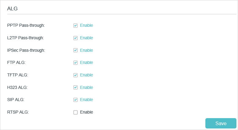
•PPTP Pass-through: If enabled, it allows Point-to-Point sessions to be tunneled through an IP network and passed through the router.
•L2TP Pass-through: If enabled, it allows Layer 2 Point-to-Point sessions to be tunneled through an IP network and passed through the router.
•IPSec Pass-through: If enabled, it allows IPSec (Internet Protocol Security) to be tunneled through an IP network and passed through the router. IPSec uses cryptographic security services to ensure private and secure communications over IP networks.
•FTP ALG: If enabled, it allows FTP (File Transfer Protocol) clients and servers to transfer data via NAT.
•TFTP ALG: If enabled, it allows TFTP (Trivial File Transfer Protocol) clients and servers to transfer data via NAT.
•H323 ALG: If enabled, it allows Microsoft NetMeeting clients to communicate via NAT.
•SIP ALG: If enabled, it allows clients communicate with SIP (Session Initiation Protocol) servers via NAT.
•RTSP ALG: If enabled, it allows RTSP (Real-Time Stream Protocol) clients and servers to transfer data via NAT.
2. Share Local Resources over the Internet by Virtual Server
When you build up a server in the local network and want to share it on the internet, Virtual Server can realize the service and provide it to the internet users. At the same time virtual server can keep the local network safe as other services are still invisible from the internet.
Virtual server can be used for setting up public services in your local network, such as HTTP, FTP, DNS, POP3/SMTP and Telnet. Different service uses different service port. Port 80 is used in HTTP service, port 21 in FTP service, port 25 in SMTP service and port 110 in POP3 service. Please verify the service port number before the configuration.
I want to:
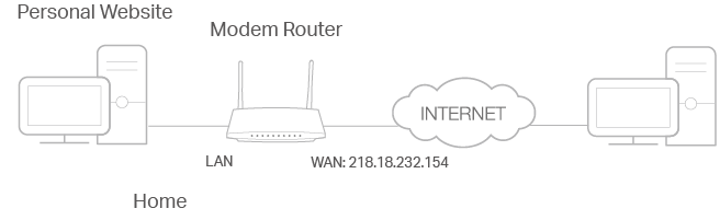
Share my personal website I’ve built in a local network with my friends through the internet.
For example, the personal website has been built on my home PC (192.168.1.100). I hope that my friends can visit my website. The PC is connected to the modem router with the WAN IP address 218.18.232.154.
How can I do that?
1.Assign a static IP address to your PC, for example 192.168.1.100.
2.Visit http://tplinkmodem.net, and log in with your TP-Link ID or the password you set for the router.
3.Go to Advanced > NAT Forwarding > Virtual Servers, click Add.
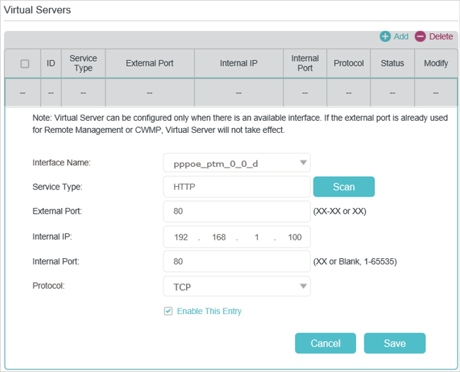
4.Click Scan, and choose HTTP. The external port, internal port and protocol will be automatically filled with contents. Enter the PC’s IP address 192.168.1.100 in the Internal IP field.
5.Click OK to save the settings.
Tips:
1.It is recommended to keep the default settings of Internal Port and Protocol if you are not clear about which port and protocol to use.
2.If the service you want to use is not in the Service Type, you can enter the corresponding parameters manually. You should verify the port number that the service needs.
3.You can add multiple virtual server rules if you want to provide several services from a modem router. Please note that the External Port cannot be overlapped.
Done!
Internet users can enter http://WAN IP (in this example: http://218.18.232.154) to visit your personal website.
Tips:
1.For a WAN IP that is assigned dynamically by ISP, it is recommended to apply and register a domain name for the WAN by DDNS, go to Set Up a Dynamic DNS Service Account for more information. Then you can use http://domain name to visit the website.
2.If you have changed the default External Port, you should use http://WAN IP: External Port or http://domain name: External Port to visit the website.
3. Open Ports Dynamically by Port Triggering
Port triggering can specify a triggering port and its corresponding external ports. When a host in the local network initiates a connection to the triggering port, all the external ports will be opened for subsequent connections. The modem router can record the IP address of the host. When the data from the internet returns to the external ports, the modem router can forward them to the corresponding host. Port triggering is mainly applied to online games, VoIPs and video players. Common applications include MSN Gaming Zone, Dialpad, Quick Time 4 players, and so on.
Follow the steps below to configure the port triggering rules:
1.Visit http://tplinkmodem.net, and log in with your TP-Link ID or the password you set for the router.
2.Go to Advanced > NAT Forwarding > Port Triggering and click Add.
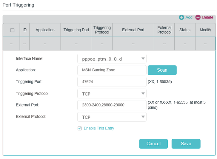
3.Click Scan, and select the desired application. The triggering port and protocol, the external port and protocol will be automatically filled with contents. Here we take MSN Gaming Zone as an example.
4.Click OK to save the settings.
Tips:
1.You can add multiple port triggering rules according to your network need.
2.If the application you need is not listed in the Existing Applications list, please enter the parameters manually. You should verify the external ports the application uses first and enter them into External Port field according to the format the page displays.
4. Make Applications Free from Port Restriction by DMZ
When a PC is set to be a DMZ (Demilitarized Zone) host in the local network, it is totally exposed to the internet, which can realize the unlimited bidirectional communication between internal hosts and external hosts. The DMZ host becomes a virtual server with all ports opened. When you are not clear about which ports to open in some special applications, like IP camera and database software, you can set the PC to be a DMZ host.
Note:
DMZ is most applicable when you don’t know which ports to open. When it is enabled, the DMZ host is totally exposed to the internet, which may bring some potential safety hazard. If DMZ is not in use, please disable it in time.
I want to:
Make the home PC join the internet online game without port restriction.
For example, Due to some port restriction, when playing the online games, you can login normally but cannot join a team with other players. To solve this problem, set your PC as a DMZ with all ports opened.
How can I do that?
1.Assign a static IP address to your PC, for example 192.168.1.100.
2.Visit http://tplinkmodem.net, and log in with your TP-Link ID or the password you set for the router.
3.Go to Advanced > NAT Forwarding > DMZ and select the checkbox to enable DMZ.
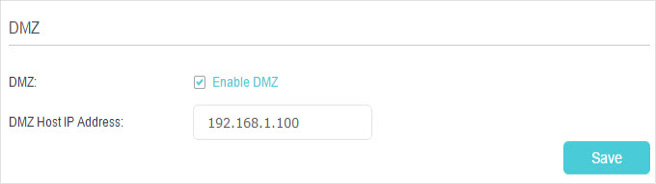
4.Enter the IP address 192.168.1.100 in the DMZ Host IP Address filed.
5.Click Save to save the settings.
Done!
The configuration is completed. You’ve set your PC to a DMZ host and now you can make a team to game with other players.
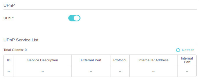
5. Make Xbox Online Games Run Smoothly by UPnP
UPnP (Universal Plug and Play) protocol allows the applications or host devices to automatically find the front-end NAT device and send request to it to open the corresponding ports. With UPnP enabled, the applications or host devices in the both sides of NAT device can freely communicate with each other realizing the seamless connection of the network. You may need to enable the UPnP if you want to use applications such as multiplayer gaming, peer-to-peer connections, real-time communication (for example, VoIP or telephone conference), or remote assistance.
Tips:
1.UPnP is enabled by default in this modem router.
2.Only the application supporting UPnP protocol can use this feature.
3.UPnP feature needs the support of operating system (e.g. Windows Vista/ Windows 7/ Windows 8, etc. Some of operating system need to install the UPnP components).
For example, when you connect your Xbox to the modem router which has connected to the internet to play online games, UPnP will send request to the modem router to open the corresponding ports allowing the following data penetrating the NAT to transmit. Therefore, you can play Xbox online games without a hitch.

If necessary, you can follow the steps to change the status of UPnP.
1.Visit http://tplinkmodem.net, and log in with your TP-Link ID or the password you set for the router.
2.Go to Advanced > NAT Forwarding > UPnP and toggle on or off according to your needs.
Application Layer Gateway Overview
Firewall policies are the method through which the firewall determines which traffic is allowed to flow between security zones and interfaces. It is a stateful process, which means that the traffic only needs to be explicitly defined in the initiating direction and replies to the valid traffic are implicitly allowed. If a user is allowed to send HTTP traffic to a server in a different zone, then the server’s replies are understood to be allowed to return to the client. This is controlled though the use of firewall sessions. The following exchange is an example of a simple TCP session, in this case HTTP is the application protocol.
ClientIP:30009 -> ServerIP:80 HTTP GET
ClientIP:30009 <- ServerIP:80 200
It is easy enough to identify the valid retuning traffic by examining the source and destination address / port values. However there are protocols that use multiple or dynamic client and server ports for different parts of the communication.
This “dynamic session” or “pinhole” in the firewall would be based on the policy that allowed the original control traffic. The secondary connection traffic would be expected to arrive at the firewall within a certain amount of time from the initial connection establishment. If it took longer, the pinhole would not be created. Effectively, the session that supports the pinhole is a child session of the initial connection traffic.
DNS
Protocol Description
The Domain Name Service provides host name to IP resolution for both the Internet and for private networks. A given DNS server will be responsible for a portion of the total DNS name space. This responsibility involves knowing the addresses or the location of the address data for all records within that portion of the DNS tree. For example, a DNS server that is authoritative for spiceup.net.in would have information on all hosts within the spiceup.net.in domain. The information may just be the name of another name server, or it could be the actual IP address.
In its simplest form, the DNS client will submit a Recursive Query to its configured Name Server. This kind of query is either answered with a successful lookup, or a record not found error. The Name server receiving the recursive query would check to see if it had the data within its own database or cache. If it did not it would begin to “walk the tree”. In the worst case it would start by querying a top level name server with a Iterative query. These queries can be answered with a successful lookup, a record not found or the name of another server with authority over the host in question. In this way the clients DNS server can work its way through the DNS namespace until it arrives at a system that can provide a definitive yes / no answer.
ALG Behavior
The DNS ALG is different then most of the other protocol ALG’s mentioned in this document. There are no secondary connections to be managed. Rather the job of the DNS ALG is to close the firewall session as soon as a reply is returned from the DNS server. DNS does not have any session tear down procedure and the sessions would remain until the protocol time out expired. The time out needs to be long enough to support the iterative query process, which could be involved. With the ALG in place DNS queries that are completed are removed from the session table in a timely manner without have to adjust the protocol time out to a level that could cause problems for slower valid queries. For IPv6 the DNS ALG will perform the IPv4 / v6 address transformations.
FTP
Protocol Description
The File Transfer Protocol (FTP) is a widely and commonly used method of exchanging files over IP networks. There are numerous vendors of both FTP clients and servers. In addition to being very common, FTP also supports data exchange between different host operating systems. The default behavior of a FTP session involves both a control and a data channel set up between the client and the server. The control channel is established from the client to the server on a well known port. TCP/21 is the assigned port for FTP, although some internet servers will host FTP on non-standard ports in an attempt to increase security through obfuscation. Once the client successfully establishes a control connection, the serve would open a data connection, originating from a port one lower then the control session. For the internet standard ports we would expect to see this connection coming from TCP/20. This default communication looks like this:
clientIP:port -> serverIP:21 USER jdoe
clientIP:port <- serverIP:21 331- User OK
clientIP:port -> serverIP:21 PASS blah
clientIP:port <- serverIP:21 230 User jdoe logged in
clientIP:port -> serverIP:21 RETR file.doc
clientIP:port <- serverIP:21 150 File OK, opening data connection
clientIP:port <- serverIP:20 DATA
clientIP:port <- serverIP:21 226 Closing data connection
There are two FTP control channel commands that can alter this behavior. One can be used to change the client port that is to receive the traffic and the other can be used to set the server data port that will listen for the user’s request. The PORT command instructs the server to make the data connection to a port other then the initiating client port. It can also be used to instruct the server to open the connection to a different IP address as well as port. It alters the communication structure as follows:
clientIP:port -> serverIP:21 USER jdoe
clientIP:port <- serverIP:21 331- User OK
clientIP:port -> serverIP:21 PASS blah
clientIP:port <- serverIP:21 230 User jdoe logged in
clientIP:port -> serverIP:21 PORT clientIP:newPort
clinetIP:port <- serverIP:21 200 Command OK
clientIP:port -> serverIP:21 RETR file.doc
clientIP:port <- serverIP:21 150 File OK, opening data connection
clientIP:newPort <- serverIP:20 DATA
clientIP:port <- serverIP:21 226 Closing data connection
The final command that affects this behavior is Passive (PASV). By placing the server into passive mode, the client becomes the one to initiate the data connection. The servers reply to the PASV command will provide the port to be used for the client initiated data transfer. The command sequence for PASV mode FTP follows:
clientIP:port -> serverIP:21 USER jdoe
clientIP:port <- serverIP:21 331- User OK
clientIP:port -> serverIP:21 PASS blah
clientIP:port <- serverIP:21 230 User jdoe logged in
clientIP:port <- serverIP:21 PASV
clinetIP:port -> serverIP:21 227 Entering Passive Mode dataPort
clientIP:port -> serverIP:21 RETR file.doc
clientIP:port -> serverIP:21 150 File OK, opening data connection
clientIP:port -> serverIP:dataPort DATA
clientIP:port <- serverIP:21 226 Closing data connection
ALG Behavior
Since FTP uses a different connection for data transfer it will require intervention of the ALG. The initial FTP request will be to a standard port (TCP/21, but others could be defined as custom services as well.) and this will invoke the ALG. For the case of the standard FTP behavior the ALG will open a pinhole for replies from the server to the client port that originate from a server port one lower then the FTP control session.
With the use of the PORT command, the ALG will parse the statement and extract the specified client port. A pinhole session holder can then be created from the server’s data port to the new client port.
Passive FTP is most commonly used to improve interoperability with firewalls. Since the client initiates both the control and the data session there is not much that the ALG needs to do. For this scenario the ALG ‘s only purpose is to associate the data session to the FTP control connection for purposes of firewall policy. In this way, a single policy allowing FTP out would also allow the client initiated data session without the need for additional policy.
In addition to this functionality, the ALG can parse and drop other FTP control channel messages. Specifically FTP-GET and PUT commands can be limited. This way a single policy could allow users to download file from a target FTP server, but not upload them, or vice versa.
The FTP ALG also monitors PORT, EPRT, PASV and 227, EPSV and 229 commands.
H.323
Protocol Description
H.323 is an older protocol designed originally to support Voice over IP type applications. In many cases it is being superseded by SIP; however it had wide deployment and will continue to be used to some degree in the near future. H.323 covers the various set up and call control functions of the media connection rather then the actual data exchange which is accomplished through RTP/RTCP. Within the H.323 specification are a number of more specific protocols that address the various needs of the media exchange. The ones of interest to our discussion include H.225.0 used in the Registration, Admission and Status (RAS) process as well as the Call Signaling Channel and H.245 which is used in the Call Control Channel.
Most H.323 communication is between a client and a gatekeeper. The gatekeeper system passes the required information between all clients on the call. Data streams and call control can also be sent directly between clients.
The first step is for a client to associate itself with a gatekeeper through a Gatekeeper Request message (GRQ). This can be unicast to one or more know gatekeeper IP addresses on UDP/1718 or multicast to the IP 224.0.1.41. After this discovery phase the client can then initiate or join calls. This portion of the communication is the RAS portion and it uses H.225.0. There are a number of messages that are sent in this phase. They will be sent to either the well know port UDP/1719 or to a dynamically assigned port specified in either the discovery (GCF – Gatekeeper Confirmation message) or the first RAS exchange (RCF – Registration Confirmation message).
Once the RAS channel is set up, the Call Signaling channel is built to either TCP/1720 or a dynamic port specified in additional RAS session messages. Following the Call Signaling Channel is the Call Control Channel which uses H.245 and connects through a dynamic port defined in the Call Signaling Channel data. Finally the clients use RTP / RTCP connections on ports defined in the H.245 data to actually send the media stream.
ALG Behavior
There are a number of requirements for the ALG in working with the H.323 stack. As can be seen there are a number potentially dynamic ports in the exchange. Each of these ports will need to be determined to open the appropriate pinholes for the return traffic. Only the initial discovery process is reliably sent on a well known port. The ALG will parse the various confirmation and response messages and extract the network and transport addresses that they contain. This data will be altered if NAT is in effect to replace public and private addresses as needed. In addition the embedded transport layer address will be used to open pinholes for future communications to the gatekeeper or peer client.
PPTP
Protocol Description
PPTP is used to provide IP security at the network layer. PPTP uses TCP 1723 for its control connection and GRE (IP protocol 47) for its PPP data. The PPTP protocol consists of a control connection and a data tunnel. The control connection runs over TCP and is used to establish and disconnect calls. The data tunnel carries PPP packets encapsulated in GRE packets which are carried over IP.
After the underlying TCP connection is established, either the client or server can send a Start Control Connection Request message to establish a control connection. The other end replies with a Start Control Connection Reply message. Either end can then request a call to be established. ScreenOS only considers clientinitiated calls. In this scenario, the client sends an Outgoing Call Request message. It assigns a call ID (bytes 12-13 of the control message) that is unique to the tunnel. The call ID is used to identify the call a particular PPP packet belongs to. The server replies with an Outgoing Call Reply message, which carries its own call ID (bytes 12-13) and the client’s call ID (bytes 14-15). The detailed working of the protocol is described in RFC
2637.
Communication between the client and server can be modeled as follows:
clientIP:port -> serverIP:1723(TCP) Start Control Connection Request
clientIP:port <- serverIP:1723(TCP) Start Control Connection Reply
clientIP:port -> serverIP:1723(TCP) Outgoing Call Request
clientIP:port <- serverIP:1723(TCP) Outgoing Call Reply
client(GRE) -> server(GRE) GRE data
client(GRE) <- server(GRE) GRE data
clientIP:port -> serverIP:1723(TCP) Call Clear Request
clientIP:port <- serverIP:1723(TCP) Call Disconnect Notify
clientIP:port -> serverIP:1723(TCP) Stop Control Connection Request
clientIP:port <- serverIP:1723(TCP) Stop Control Connection Reply
ALG Behavior
The ALG parses the control messages, looking for the Outgoing Call Request and Outgoing Call Reply messages, open up one gate to accept GRE traffic sent by the server and the other gate to accept GRE traffic sent by the client. Each of the gates opened above will create a session for data traffic arriving in that direction. This means that there will be 2 data sessions opened for each tunnel: one for client-to-server traffic using the server’s call ID as the destination port and the other for server-to-client traffic using the client’s translated call ID as the destination port. The ALG can support PAT for PPTP on all platforms.
ALG Timeout
The default timeout value of the control connection will be 30 minute. The data session will use the same timeout value. So if the data session is idle for too long it will be closed. When the parent control session terminates, then all the data session created by the control connection will also be closed. The call ID value for the session can be reused after the session is closed and no earlier than that.
SQL
Protocol Description
Oracle SQL*Net is a network access protocol for Oracle databases. In operation a database client would connect to the Oracle server on the well known port of TCP/1521 or TCP/1525 for SQL*Net V1. The server would then send the client connection information for the actual data communication. The main reason for this behavior is that SQL*Net was developed at a time when there were a very wide range of network protocols in use, and it was designed to be independent of any particular transport. TOP/IP was only one of more then 8 options in the original SQL*Net specification.
ALG Behavior
This is a very straight forward ALG. It will parse any replies from TCP/1521 and look for the string “(IP=a.b.c.d)(PORT=x)” in ASCII and then open a pin hole for the subsequent server connection. Nat can also be applied at this point to translate public to private IP addresses and vice versa.
ALG Timeout
The control channel on TCP/1521 (1525) is not linked with the resulting data connection. While the SQL session inherits the time out from this connection, they are not linked and the control channel can time out without effecting the data channel.
TFTP
Protocol Description
TFTP is a protocol used to transfer files. It runs on top of UDP, with port 69 as the well known port. TFTP ALG processes TFTP packets that initiate the request and creates pinholes to allow return packets from the reversedirection.
Communication between the client and server can be modeled as follows:
(1) Write request:
clientIP:port -> serverIP:69(UDP) WRQ
clientIP:port <- serverIP: 69(UDP)ACK
(2) Read request:
clientIP:port -> serverIP:69(UDP) RRQ
clientIP:port <- serverIP: 69(UDP)DATA
ALG Behavior
The ALG processes TFTP packet that initiate the request and opens gate to allow return packets from the reverse direction to the port that sends the request. ALG Timeout The default timeout value of the control connection will be 30 minute. The data session will use the same timeout value.
 |
| Leave your comment below |