EIGRP
The Enhanced Interior Gateway Routing Protocol (EIGRP) is an enhanced version of the Interior Gateway Routing Protocol (IGRP)
developed by Cisco. The convergence properties and the operating efficiency of EIGRP have improved substantially over IGRP,
and IGRP is now obsolete.
The convergence technology of EIGRP is based on an algorithm called the Diffusing Update Algorithm (DUAL). The algorithm guarantees
loop-free operation at every instant throughout a route computation and allows all devices involved in a topology change to
synchronize. Devices that are not affected by topology changes are not involved in recomputations.
Information About Configuring EIGRP
EIGRP Features
-
Increased network width—With IP Routing Information Protocol (RIP), the largest possible width of your network is 15 hops.
When EIGRP is enabled, the largest possible width is increased to 100 hops, and the EIGRP metric is large enough to support
thousands of hops. -
Fast convergence—The DUAL algorithm allows routing information to converge as quickly as any currently available routing
protocol. -
Partial updates—EIGRP sends incremental updates when the state of a destination changes, instead of sending the entire contents
of the routing table. This feature minimizes the bandwidth required for EIGRP packets. -
Neighbor discovery mechanism—This simple protocol-independent hello mechanism is used to learn about neighboring devices.
-
Scaling—EIGRP scales to large networks.
EIGRP Autonomous System Configuration
Configuring the
router
eigrp command with the
autonomous-system-number argument creates an EIGRP configuration called the EIGRP autonomous system configuration, or EIGRP classic mode. The EIGRP
autonomous system configuration creates an EIGRP routing instance that can be used for exchanging routing information.
In EIGRP autonomous system configurations, EIGRP VPNs can be configured only under IPv4 address family configuration mode.
A virtual routing and forwarding (VRF) instance and a route distinguisher must be defined before the address family session
can be created.
When the address family is configured, we recommend that you configure an autonomous system number either by using the
autonomous-system-number argument with the
address-family command or by using the
autonomous-system command.
EIGRP Named Configuration
Configuring the
router
eigrp command with the
virtual-instance-name argument creates an EIGRP configuration referred to as the EIGRP named configuration or EIGRP named mode. An EIGRP named
configuration does not create an EIGRP routing instance by itself; it is a base configuration that is required to define address-family
configurations that are used for routing.
In EIGRP named configurations, EIGRP VPNs can be configured in IPv4 and IPv6 named configurations. A VRF instance and a route
distinguisher must be defined before the address family session can be created.
A single EIGRP routing process can support multiple VRFs. The number of VRFs that can be configured is limited only by the
available system resources on the device, which is determined by the number running processes and available memory. However,
only a single VRF can be supported by each VPN, and redistribution between different VRFs is not supported.
EIGRP Neighbor Relationship Maintenance
Neighbor relationship maintenance is the process that devices use to dynamically learn of other devices on their directly
attached networks. Devices must also discover when their neighbors become unreachable or inoperative. Neighbor relationship
maintenance is achieved with low overhead by devices when they periodically send small hello packets to each other. As long
as hello packets are received, the Cisco software can determine whether a neighbor is alive and functioning. After the status
of the neighbor is determined, neighboring devices can exchange routing information.
The reliable transport protocol is responsible for the guaranteed, ordered delivery of Enhanced Interior Gateway Routing
Protocol (EIGRP) packets to all neighbors. The reliable transport protocol supports intermixed transmission of multicast and
unicast packets. Some EIGRP packets (such as updates) must be sent reliably; this means that the packets require acknowledgment
from the destination. For efficiency, reliability is provided only when necessary. For example, on a multiaccess network that
has multicast capabilities, hello packets need not be sent reliably to all neighbors individually. Therefore, EIGRP sends
a single multicast hello packet with an indication in the packet informing receivers that the packet need not be acknowledged.
The reliable transport protocol can send multicast packets quickly when unacknowledged packets are pending, thereby ensuring
that the convergence time remains low in the presence of varying speed links.
Some EIGRP remote unicast-listen (any neighbor that uses unicast to communicate) and remote multicast-group neighbors may
peer with any device that sends a valid hello packet, thus causing security concerns. By authenticating the packets that are
exchanged between neighbors, you can ensure that a device accepts packets only from devices that know the preshared authentication
key.
Neighbor Authentication
The authentication of packets being sent between neighbors ensures that a device accepts packets only from devices that have
the same preshared key. If this authentication is not configured, you can intentionally or accidentally add another device
to the network or send packets with different or conflicting route information onto the network, resulting in topology corruption
and denial of service (DoS).
Enhanced Interior Gateway Routing Protocol (EIGRP) authentication is configurable on a per-interface basis; packets exchanged
between neighbors connected through an interface are authenticated. EIGRP supports message digest algorithm 5 (MD5) authentication
to prevent the introduction of unauthorized information from unapproved sources. MD5 authentication is defined in RFC 1321.
DUAL Finite State Machine
The DUAL finite state machine embodies the decision process for all route computations. It tracks all routes advertised by
all neighbors. DUAL uses the distance information (known as the metric) to select efficient, loop-free paths. DUAL selects
routes to be inserted into a routing table based on feasible successors. A successor is a neighboring device (used for packet
forwarding) that has the least-cost path to a destination that is guaranteed not to be part of a routing loop. When there
are no feasible successors but only neighbors advertising the destination, a recomputation must occur to determine a new successor.
The time required to recompute the route affects the convergence time. Recomputation is processor-intensive, and unnecessary
recomputation must be avoided. When a topology change occurs, DUAL will test for feasible successors. If there are feasible
successors, DUAL will use any feasible successors it finds to avoid unnecessary recomputation.
Protocol-Dependent Modules
Protocol-dependent modules are responsible for network-layer protocol-specific tasks. An example is the EIGRP module, which
is responsible for sending and receiving EIGRP packets that are encapsulated in the IP. The EIGRP module is also responsible
for parsing EIGRP packets and informing DUAL about the new information received. EIGRP asks DUAL to make routing decisions,
but the results are stored in the IP routing table. Also, EIGRP is responsible for redistributing routes learned from other
IP routing protocols.
Goodbye Message
The goodbye message is a feature designed to improve EIGRP network convergence. The goodbye message is broadcast when an
EIGRP routing process is shut down to inform adjacent peers about an impending topology change. This feature allows supporting
EIGRP peers to synchronize and recalculate neighbor relationships more efficiently than would occur if the peers discovered
the topology change after the hold timer expired.
The following message is displayed by devices that run a supported release when a goodbye message is received:
*Apr 26 13:48:42.523: %DUAL-5-NBRCHANGE: IP-EIGRP(0) 1: Neighbor 10.1.1.1 (Ethernet0/0) is down: Interface Goodbye received
A Cisco device that runs a software release that does not support the goodbye message can misinterpret the message as a K-value
mismatch and display the following error message:
*Apr 26 13:48:41.811: %DUAL-5-NBRCHANGE: IP-EIGRP(0) 1: Neighbor 10.1.1.1 (Ethernet0/0) is down: K-value mismatch
Note |
The receipt of a goodbye message by a nonsupporting peer does not disrupt normal network operation. The nonsupporting peer |
EIGRP Metric Weights
You can use the
metric
weights command to adjust the default behavior of Enhanced Interior Gateway Routing Protocol (EIGRP) routing and metric computations.
EIGRP metric defaults (K values) have been carefully selected to provide optimal performance in most networks.
|
Note |
Adjusting EIGRP metric weights can dramatically affect network performance. Because of the complexity of this task, we recommend |
By default, the EIGRP composite cost metric is a 32-bit quantity that is the sum of segment delays and the lowest segment
bandwidth (scaled and inverted) for a given route. The formula used to scale and invert the bandwidth value is 107/minimum bandwidth in kilobits per second. However, with the EIGRP Wide Metrics feature, the EIGRP composite cost metric is
scaled to include 64-bit metric calculations for EIGRP named mode configurations.
For a network of homogeneous media, this metric reduces to a hop count. For a network of mixed media (FDDI, Gigabit Ethernet
(GE), and serial lines running from 9600 bits per second to T1 rates), the route with the lowest metric reflects the most
desirable path to a destination.
Mismatched K Values
EIGRP K values are the metrics that EIGRP uses to calculate routes. Mismatched K values can prevent neighbor relationships
from being established and can negatively impact network convergence. The example given below explains this behavior between
two EIGRP peers (Device-A and Device-B).
The following configuration is applied to Device-A. The K values are changed using the
metric
weights command. A value of 2 is entered for the
k1 argument to adjust the bandwidth calculation. A value of 1 is entered for the
k3 argument to adjust the delay calculation.
Device(config)# hostname Device-A
Device-A(config)# interface serial 0
Device-A(config-if)# ip address 10.1.1.1 255.255.255.0
Device-A(config-if)# exit
Device-A(config)# router eigrp name1
Device-A(config-router)# address-family ipv4 autonomous-system 4533
Device-A(config-router-af)# network 10.1.1.0 0.0.0.255
Device-A(config-router-af)# metric weights 0 2 0 1 0 0 1
The following configuration is applied to Device-B, and the default K values are used. The default K values are 1, 0, 1,
0, 0, and 0.
Device(config)# hostname Device-B
Device-B(config)# interface serial 0
Device-B(config-if)# ip address 10.1.1.2 255.255.255.0
Device-B(config-if)# exit
Device-B(config)# router eigrp name1
Device-B(config-router)# address-family ipv4 autonomous-system 4533
Device-B(config-router-af)# network 10.1.1.0 0.0.0.255
Device-B(config-router-af)# metric weights 0 1 0 1 0 0 0
The bandwidth calculation is set to 2 on Device-A and set to 1 (by default) on Device-B. This configuration prevents these
peers from forming a neighbor relationship.
The following error message is displayed on the console of Device-B because the K values are mismatched:
*Apr 26 13:48:41.811: %DUAL-5-NBRCHANGE: IP-EIGRP(0) 1: Neighbor 10.1.1.1 (Ethernet0/0) is down: K-value mismatch
The following are two scenarios where the above error message can be displayed:
-
Two devices are connected on the same link and configured to establish a neighbor relationship. However, each device is configured
with different K values. -
One of two peers has transmitted a “peer-termination” message (a message that is broadcast when an EIGRP routing process
is shut down), and the receiving device does not support this message. The receiving device will interpret this message as
a K-value mismatch.
Routing Metric Offset Lists
An offset list is a mechanism for increasing incoming and outgoing metrics to routes learned via EIGRP. Optionally, you can
limit the offset list with either an access list or an interface.
|
Note |
Offset lists are available only in IPv4 configurations. IPv6 configurations do not support offset lists. |
EIGRP Cost Metrics
When EIGRP receives dynamic raw radio link characteristics, it computes a composite EIGRP cost metric based on a proprietary
formula. To avoid churn in the network as a result of a change in the link characteristics, a tunable dampening mechanism
is used.
EIGRP uses metric weights along with a set of vector metrics to compute the composite metric for local RIB installation and
route selections. The EIGRP composite cost metric is calculated using the formula:
EIGRP composite cost metric = 256*((K1*Bw) + (K2*Bw)/(256 – Load) + (K3*Delay)*(K5/(Reliability + K4)))
EIGRP uses one or more vector metrics to calculate the composite cost metric. The table below lists EIGRP vector metrics
and their descriptions.
|
Vector Metric |
|
|---|---|
|
bandwidth |
The minimum bandwidth of the route, in kilobits per second. It can be 0 or any positive integer. The bandwidth for the formula (107/minimum bandwidth (Bw) in kilobits per second) |
|
delay |
Route delay, in tens of microseconds. |
|
delay reliability |
The likelihood of successful packet transmission, expressed as a number between 0 and 255, where 255 means 100 percent reliability |
|
load |
The effective load of the route, expressed as a number from 0 to 255 (255 is 100 percent loading). |
|
mtu |
The minimum maximum transmission unit (MTU) size of the route, in bytes. It can be 0 or any positive integer. |
EIGRP monitors metric weights on an interface to allow the tuning of EIGRP metric calculations and indicate the type of service
(ToS). The table below lists the K values and their defaults.
|
Setting |
Default Value |
|---|---|
|
K1 |
1 |
|
K2 |
0 |
|
K3 |
1 |
|
K4 |
0 |
|
K5 |
0 |
Most configurations use the delay and bandwidth metrics, with bandwidth taking precedence. The default formula of 256*(Bw
+ Delay) is the EIGRP metric. The bandwidth for the formula is scaled and inverted by the following formula:
(107/minimum Bw in kilobits per second)
|
Note |
You can change the weights, but these weights must be the same on all devices. |
For example, look at a link whose bandwidth to a particular destination is 128 k and the delay is 84,000 microseconds.
By using a cut-down formula, you can simplify the EIGRP metric calculation to 256*(Bw + Delay), thus resulting in the following
value:
Metric = 256*(107/128 + 84000/10) = 256*86525 = 22150400
To calculate route delay, divide the delay value by 10 to get the true value in tens of microseconds.
When EIGRP calculates the delay for Mobile Ad Hoc Networks (MANET) and the delay is obtained from a device interface, the
delay is always calculated in tens of microseconds. In most cases, when using MANET, you will not use the interface delay,
but rather the delay that is advertised by the radio. The delay you will receive from the radio is in microseconds, so you
must adjust the cut-down formula as follows:
Metric = (256*(107/128) + (84000*256)/10) = 20000000 + 2150400 = 22150400
Route Summarization
You can configure EIGRP to perform automatic summarization of subnet routes into network-level routes. For example, you can
configure subnet 172.16.1.0 to be advertised as 172.16.0.0 over interfaces that have been configured with subnets of 192.168.7.0.
Automatic summarization is performed when two or more network router configuration or address family configuration commands are configured for an EIGRP process. This feature is enabled
by default.
Route summarization works in conjunction with the ip
summary-address
eigrp command available in interface configuration mode for autonomous system configurations and with the summary-address (EIGRP) command for named configurations. You can use these commands to perform additional summarization. If automatic summarization
is in effect, there usually is no need to configure network-level summaries using the ip
summary-address
eigrp command.
Summary Aggregate Addresses
You can configure a summary aggregate address for a specified interface. If there are specific routes in the routing table,
EIGRP will advertise the summary address of the interface with a metric equal to the minimum metric of the specific routes.
Floating Summary
Routes
A floating summary
route is created by applying a default route and an administrative distance at
the interface level or address family interface level. You can use a floating
summary route when configuring the
ip
summary-address
eigrp command for autonomous system configurations
or the
summary-address
command for named configurations. The following scenarios illustrate the
behavior of floating summary routes.
The figure below
shows a network with three devices, Device-A, Device-B, and Device-C. Device-A
learns a default route from elsewhere in the network and then advertises this
route to Device-B. Device-B is configured so that only a default summary route
is advertised to Device-C. The default summary route is applied to serial
interface 0/1 on Device-B with the following autonomous system configuration:
Device-B(config)# interface Serial 0/1
Device-B(config-if)# ip summary-address eigrp 100 0.0.0.0 0.0.0.0
The default summary
route is applied to serial interface 0/1 on Device-B with the following named
configuration:
Device-B(config)# Router eigrp virtual-name1
Device-B(config-router)# address-family ipv4 unicast vrf vrf1 autonomous-system 1
Device-B(config-router-af)# interface serial 0/1
Device-B(config-router-af-interface)# summary-address 192.168.0.0 255.255.0.0 95
Applied to Device-B
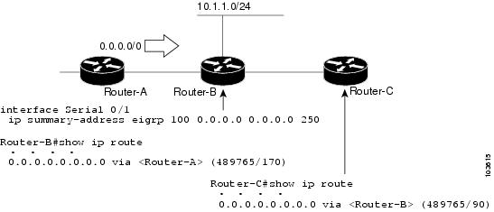
The configuration of
the default summary route on Device-B sends a 0.0.0.0/0 summary route to
Device-C and blocks all other routes, including the 10.1.1.0/24 route, from
being advertised to Device-C. However, this configuration also generates a
local discard route—a route for 0.0.0.0/0 on the null 0 interface with an
administrative distance of 5—on Device-B. When this route is created, it
overrides the EIGRP-learned default route. Device-B will no longer be able to
reach destinations that it would normally reach through the 0.0.0.0/0 route.
This problem is
resolved by applying a floating summary route to the interface on Device-B that
connects to Device-C. The floating summary route is applied by configuring an
administrative distance for the default summary route on the interface of
Device-B with the following statement for an autonomous system configuration:
Device-B(config-if)# ip summary-address eigrp 100 0.0.0.0 0.0.0.0 250
The floating summary
route is applied by configuring an administrative distance for the default
summary route on the interface of Device-B with the following statement for a
named configuration:
Device-B(config)# router eigrp virtual-name1
Device-B(config-router)# address-family ipv4 unicast vrf vrf1 autonomous-system 1
Device-B(config-router-af)# af-interface serial0/1
Device-B(config-router-af-interface)# summary-address eigrp 100 0.0.0.0 0.0.0.0 250
The administrative
distance of 250, applied in the
summary-address
command, is now assigned to the discard route generated on Device-B. The
0.0.0.0/0, from Device-A, is learned through EIGRP and installed in the local
routing table. Routing to Device-C is restored.
If Device-A loses the
connection to Device-B, Device-B will continue to advertise a default route to
Device-C, which allows traffic to continue to reach destinations attached to
Device-B. However, traffic destined to networks connected to Device-A or behind
Device-A will be dropped when the traffic reaches Device-B.
The figure below
shows a network with two connections from the core, Device-A and Device-D. Both
Device-B and Device-E have floating summary routes configured on the interfaces
connected to Device-C. If the connection between Device-E and Device-C fails,
the network will continue to operate normally. All traffic will flow from
Device-C through Device-B to hosts attached to Device-A and Device-D.
Applied for Dual-Homed Remotes
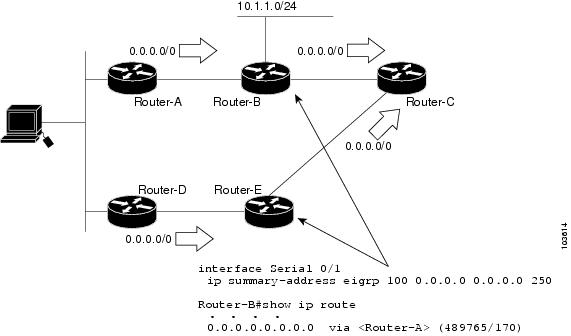
However, if the link between Device-A and Device-B fails, the network may incorrectly direct traffic because Device-B will
continue to advertise the default route (0.0.0.0/0) to Device-C. In this scenario, Device-C still forwards traffic to Device-B,
but Device-B drops the traffic. To avoid this problem, you should configure the summary address with an administrative distance
only on single-homed remote devices or areas that have only one exit point between two segments of the network. If two or
more exit points exist (from one segment of the network to another), configuring the floating default route can result in
the formation of a null route (a route that has quick packet dropping capabilities).
Hello Packets and the Hold-Time Intervals
You can adjust the interval between hello packets and the hold time. Hello packets and hold-time intervals are protocol-independent
parameters that work for IP and Internetwork Packet Exchange (IPX).
Routing devices periodically send hello packets to each other to dynamically learn of other devices on their directly attached
networks. This information is used to discover neighbors and to learn when neighbors become unreachable or inoperative.
By default, hello packets are sent every 5 seconds. The exception is on low-speed, nonbroadcast multiaccess (NBMA) media,
where the default hello interval is 60 seconds. Low speed is considered to be a rate of T1 or slower, as specified with the
bandwidth interface configuration command. The default hello interval remains 5 seconds for high-speed NBMA networks. Note that for
the purposes of EIGRP, Frame Relay and Switched Multimegabit Data Service (SMDS) networks may or may not be considered to
be NBMA. These networks are considered NBMA only if the interface has not been configured to use physical multicasting.
You can configure the hold time on a specified interface for a particular EIGRP routing process designated by the autonomous
system number. The hold time is advertised in hello packets and indicates to neighbors the length of time they should consider
the sender valid. The default hold time is three times the hello interval or 15 seconds. For slow-speed NBMA networks, the
default hold time is 180 seconds.
On very congested and large networks, the default hold time might not be sufficient for all devices to receive hello packets
from their neighbors. In such cases, you may want to increase the hold time.
|
Note |
Do not adjust the hold time without informing your technical support personnel. |
Split Horizon
Split horizon controls the sending of EIGRP update and query packets. Split horizon is a protocol-independent parameter that
works for IP and IPX. When split horizon is enabled on an interface, update and query packets are not sent to destinations
for which this interface is the next hop. Controlling update and query packets in this manner reduces the possibility of routing
loops.
By default, split horizon is enabled on all interfaces.
Split horizon blocks route information from being advertised by a device out of any interface from which that information
originated. This behavior usually optimizes communications among multiple routing devices, particularly when links are broken.
However, with nonbroadcast networks (such as Frame Relay and SMDS), situations can arise for which this behavior is less than
ideal. In such situations and in networks that have EIGRP configured, you may want to disable split horizon.
EIGRP Dual DMVPN Domain Enhancement
The EIGRP Dual DMVPN Domain Enhancement feature supports the
no next-hop self command on dual Dynamic Multipoint VPN (DMVPN) domains in both IPv4 and IPv6 configurations.
EIGRP, by default, sets the local outbound interface as the next-hop value while advertising a network to a peer, even when
advertising routes out of the interface on which the routes were learned. This default setting can be disabled by using the
no ip next-hop-self command in autonomous system configurations or the
no next-hop-self command in named configurations. When the
next-hop self command is disabled, EIGRP does not advertise the local outbound interface as the next hop if the route has been learned
from the same interface. Instead, the received next-hop value is used to advertise learned routes. However, this functionality
only evaluates the first entry in the EIGRP table. If the first entry shows that the route being advertised is learned on
the same interface, then the received next hop is used to advertise the route. The
no next-hop-self configuration ignores subsequent entries in the table, which may result in the
no-next-hop-self configuration being dishonored on other interfaces.
The EIGRP Dual DMVPN Domain Enhancement feature introduces the
no-ecmp-mode keyword, which is an enhancement to the
no next-hop-self and
no ip next-hop-self commands. When this keyword is used, all routes to a network in the EIGRP table are evaluated to check whether routes advertised
from an interface were learned on the same interface. If a route advertised by an interface was learned on the same interface,
the
no next-hop-self configuration is honored and the received next hop is used to advertise this route.
Link Bandwidth Percentage
By default, EIGRP packets consume a maximum of 50 percent of the link bandwidth when configured with the
bandwidth interface configuration command for autonomous system configurations and with the
bandwidth-percent command for named configurations. You might want to change the bandwidth value if a different level of link utilization is
required or if the configured bandwidth does not match the actual link bandwidth (which may have been configured to influence
route metric calculations). This is a protocol-independent parameter that works for IP and IPX.
EIGRP vNETs
The EIGRP vNET feature uses Layer 3 routing techniques to provide limited fate sharing (the term fate sharing refers to the
failure of interconnected systems; that is, different elements of a network are interconnected in such a way that they either
fail together or not at all), traffic isolation, and access control with simple configurations. EIGRP virtual network (vNET)
configurations are supported in both autonomous-system configurations and named configurations.
The vNET feature allows you to have multiple virtual networks by utilizing a single set of routers and links provided by the
physical topology. Routers and links can be broken down into separate virtual networks using separate routing tables and routing
processes by using vNETs and VRF configuration commands. The virtual networks facilitate traffic isolation and limited fate
sharing. EIGRP’s primary role in vNETs is to populate routing tables used by each vNET so that appropriate forwarding can
take place. In the vNET model, each vNET effectively has its own complete set of EIGRP processes and resources, thus minimizing
the possibility of actions within one vNET affecting another vNET.
The vNET feature supports command inheritance that allows commands entered in interface configuration mode to be inherited
by every vNET configured on that interface. These inherited commands, including EIGRP interface commands, can be overridden
by vNET-specific configurations in vNET submodes under the interface.
The following are some of the limitations of EIGRP vNETs:
-
EIGRP does not support Internetwork Packet Exchange (IPX) within a vNET.
-
vNET and VRF configurations are mutually exclusive on an interface. Both VRFs and vNETs can be configured on the router, but
they cannot both be defined on the same interface. A VRF cannot be configured within a vNET and a vNET cannot be configured
within a VRF. -
Each vNET has its own routing table, and routes cannot be redistributed directly from one vNET into another. EIGRP uses the
route replication functionality to meet the requirements of shared services and to copy routes from one vNET Routing Information
Base (RIB) to other vNET RIBs. -
Bidirectional Forwarding Detection (BFD) is not supported with EIGRP mode vNET.
EIGRP vNET Interface and Command Inheritance
A vNET router supports two types of interfaces: Edge interface and core (shared) interface.
An edge interface is an ingress point for vNET-unaware networks and is restricted to a single VRF. Use the
vrf forwarding command to associate the edge interface with a VRF. The
vrf forwarding command also allows entry into VRF submodes used to define interface settings on a per-VRF basis.
A vNET core interface is used to connect vNET-aware systems and can be shared by multiple vNETs. Use the
vnet trunk command to enable a core interface.
When the
vnet trunk command exists on an interface, with or without a VRF list, any EIGRP interface commands on that interface will be applied
to the EIGRP instance for every vNET on that interface, including the instance running on the base or the global RIB. If the
vnet trunk command is deleted from the interface, EIGRP interface commands will remain on and apply to only the global EIGRP instance.
If an EIGRP interface command is removed from the main interface, the command will also be removed from every vNET on that
interface.
End systems or routing protocol peers reached through an edge interface are unaware of vNETs and do not perform the vNET tagging
done in the core of the vNET network.
EIGRP also supports the capability of setting per-vNET interface configurations, which allow you to define interface attributes
that influence EIGRP behavior for a single vNET. In the configuration hierarchy, a specific vNET interface setting has precedence
over settings applied to the entire interface and inherited by each vNET configured on that interface.
EIGRP provides interface commands to modify the EIGRP-specific attributes of an interface, and these interface commands can
be entered directly on the interface for EIGRP autonomous system configurations, or in address family interface configuration
mode for the EIGRP named mode configurations.
How to Configure EIGRP
Enabling EIGRP Autonomous System Configuration
Perform this task to enable EIGRP and create an EIGRP routing process. EIGRP sends updates to interfaces in specified networks.
If you do not specify the network of an interface, the interface will not be advertised in any EIGRP update.
Configuring the
router
eigrp
autonomous-system-number command creates an EIGRP autonomous system configuration that creates an EIGRP routing instance, which can be used for tagging
routing information.
SUMMARY STEPS
-
enable
-
configure
terminal
-
router
eigrp
autonomous-system-number
-
network
network-number
-
end
DETAILED STEPS
| Command or Action | Purpose | |
|---|---|---|
|
Step 1 |
Example: |
Enables privileged EXEC mode.
|
|
Step 2 |
Example: |
Enters global configuration mode. |
|
Step 3 |
Example: |
Configures an EIGRP routing process and enters router configuration mode.
|
|
Step 4 |
Example: |
Associates a network with an EIGRP routing process. |
|
Step 5 |
Example: |
Exits router configuration mode and returns to privileged EXEC mode. |
EIGRP Named Configuration
Configuring the
router
eigrp command with the
virtual-instance-name argument creates an EIGRP configuration referred to as the EIGRP named configuration or EIGRP named mode. An EIGRP named
configuration does not create an EIGRP routing instance by itself; it is a base configuration that is required to define address-family
configurations that are used for routing.
In EIGRP named configurations, EIGRP VPNs can be configured in IPv4 and IPv6 named configurations. A VRF instance and a route
distinguisher must be defined before the address family session can be created.
A single EIGRP routing process can support multiple VRFs. The number of VRFs that can be configured is limited only by the
available system resources on the device, which is determined by the number running processes and available memory. However,
only a single VRF can be supported by each VPN, and redistribution between different VRFs is not supported.
Configuring Optional EIGRP Parameters in an Autonomous System Configuration
Perform this task to configure optional EIGRP parameters, which include applying offsets to routing metrics, adjusting EIGRP
metrics, and disabling automatic summarization in an EIGRP autonomous system configuration.
SUMMARY STEPS
-
enable
-
configure
terminal
-
router
eigrp
autonomous-system
-
network
ip-address
[wildcard-mask ] -
passive-interface
[default ] [interface-type
interface-number ] -
offset-list
[access-list-number |
access-list-name ] {in |
out }
offset [interface-type
interface-number ] -
metric
weights
tos
k1
k2
k3
k4
k5
-
no
auto-summary
-
end
DETAILED STEPS
| Command or Action | Purpose | |||
|---|---|---|---|---|
|
Step 1 |
Example: |
Enables privileged EXEC mode.
|
||
|
Step 2 |
Example: |
Enters global configuration mode. |
||
|
Step 3 |
Example: |
Enables an EIGRP routing process and enters router configuration mode.
|
||
|
Step 4 |
Example: |
Associates networks with an EIGRP routing process. |
||
|
Step 5 |
Example: |
(Optional) Suppresses EIGRP hello packets and routing updates on interfaces while still including the interface addresses |
||
|
Step 6 |
Example: |
(Optional) Applies an offset to routing metrics. |
||
|
Step 7 |
Example: |
(Optional) Adjusts the EIGRP metric or K value.
EIGRP Metric = 256*((K1*Bw) + (K2*Bw)/(256-Load) + (K3*Delay)*(K5/(Reliability + K4)))
|
||
|
Step 8 |
Example: |
(Optional) Disables automatic summarization.
|
||
|
Step 9 |
Example: |
Exits router configuration mode and returns to privileged EXEC mode. |
Configuring Optional EIGRP
Parameters in a Named Configuration
Perform this task
to configure optional EIGRP named configuration parameters, which includes
applying offsets to routing metrics, adjusting EIGRP metrics, setting the
RIB-scaling factor, and disabling automatic summarization.
SUMMARY STEPS
-
enable -
configure
terminal
-
routereigrp
virtual-instance-name
- Enter one of the
following: -
address-family ipv4 [unicast] [vrf
vrf-name] [multicast]
autonomous-system
autonomous-system-number -
address-family
ipv6
[unicast] [vrf
vrf-name]
autonomous-system
autonomous-system-number -
network
ip-address
[wildcard-mask ] -
metricweights
tos
k1
k2
k3
k4
k5
k6 -
af-interface
interface-type
interface-number} -
passive-interface
-
bandwidth-percent
maximum-bandwidth-percentage -
exit-af-interface
-
topology {base |
topology-name
tid
number} -
offset-list [access-list-number |
access-list-name] {in |
out}offset [interface-type
interface-number] -
no
auto-summary
-
end
DETAILED STEPS
| Command or Action | Purpose | |||
|---|---|---|---|---|
|
Step 1 |
Example: |
Enables
|
||
|
Step 2 |
Example: |
Enters global |
||
|
Step 3 |
eigrp Example: |
Enables an |
||
|
Step 4 |
Enter one of the
Example: |
Enters address |
||
|
Step 5 |
Example: |
Specifies a |
||
|
Step 6 |
weights Example: |
(Optional)
|
||
|
Step 7 |
Example: |
Enters address family interface configuration mode and configures interface-specific EIGRP commands. |
||
|
Step 8 |
Example: |
Suppresses |
||
|
Step 9 |
Example: |
Configures |
||
|
Step 10 |
Example: |
Exits address |
||
|
Step 11 |
Example: |
Configures an |
||
|
Step 12 |
offset [interface-type Example: |
(Optional) |
||
|
Step 13 |
Example: |
(Optional)
|
||
|
Step 14 |
Example: |
Returns to |
Configuring the EIGRP
Redistribution Autonomous System Configuration
Perform this task
to configure redistribution of non-EIGRP protocol metrics into EIGRP metrics
and to configure the EIGRP administrative distance in an EIGRP autonomous
system configuration.
You must use a
default metric to redistribute a protocol into EIGRP, unless you use the
redistribute
command.
|
Note |
Metric defaults |
Default metrics are
supported only when you are redistributing from EIGRP or static routes.
An administrative
distance is a rating of the trustworthiness of a routing information source,
such as an individual router or a group of routers. Numerically, an
administrative distance is an integer from 0 to 255. In general, the higher the
value the lower the trust rating. An administrative distance of 255 means the
routing information source cannot be trusted at all and should be ignored.
SUMMARY STEPS
-
enable -
configure
terminal
-
routereigrp
autonomous-system
-
network
ip-address
[wildcard-mask ] -
redistribute
protocol
-
distance
eigrp
internal-distance
external-distance
-
default-metric
bandwidth
delay
reliability
loading
mtu
-
end
DETAILED STEPS
| Command or Action | Purpose | |
|---|---|---|
|
Step 1 |
Example: |
Enables
|
|
Step 2 |
Example: |
Enters global |
|
Step 3 |
eigrp Example: |
Enables an
|
|
Step 4 |
Example: |
Associates |
|
Step 5 |
Example: |
Redistributes |
|
Step 6 |
Example: |
Allows the |
|
Step 7 |
Example: |
Sets metrics |
|
Step 8 |
Example: |
Exits router |
Configuring the EIGRP Route
Summarization Autonomous System Configuration
Perform this task
to configure EIGRP to perform automatic summarization of subnet routes into
network-level routes in an EIGRP autonomous system configuration.
SUMMARY STEPS
-
enable -
configure
terminal
-
routereigrp
autonomous-system
- no
auto-summary -
exit
-
interface type
number
- no
switchport - bandwidth
kpbs -
ip
summary-address
eigrp
as-number
ip-address
mask
[admin-distance ]
[leak-map
name ] -
ip
bandwidth-percent
eigrp
as-number
percent
-
end
DETAILED STEPS
| Command or Action | Purpose | |
|---|---|---|
|
Step 1 |
Example: |
Enables
|
|
Step 2 |
Example: |
Enters global |
|
Step 3 |
eigrp Example: |
Enables an
|
|
Step 4 |
no Example: |
Disables |
|
Step 5 |
Example: |
Exits router |
|
Step 6 |
Example: |
Enters |
|
Step 7 |
no Example: |
Puts an interface into Layer 3 mode |
|
Step 8 |
bandwidth Example: |
Sets the |
|
Step 9 |
Example: |
(Optional) |
|
Step 10 |
Example: |
(Optional) |
|
Step 11 |
Example: |
Exits |
Configuring the EIGRP Route Summarization Named Configuration
Perform this task to configure EIGRP to perform automatic summarization of subnet routes into network-level routes in an
EIGRP named configuration.
SUMMARY STEPS
-
enable
-
configure
terminal
-
router
eigrp
virtual-instance-name
- Enter one of the following:
-
address-family
ipv4
[multicast ] [unicast ] [vrf
vrf-name ]
autonomous-system
autonomous-system-number -
address-family
ipv6
[unicast ] [vrf
vrf-name ]
autonomous-system
autonomous-system-number -
af-interface {default | interface-type interface-number}
-
summary-address
ip-address
mask
[administrative-distance [leak-map
leak-map-name ]] -
exit-af-interface
-
topology
{base |
topology-name
tid
number } -
summary-metric
network-address
subnet-mask
bandwidth
delay
reliability
load
mtu
-
end
DETAILED STEPS
| Command or Action | Purpose | |
|---|---|---|
|
Step 1 |
Example: |
Enables privileged EXEC mode.
|
|
Step 2 |
Example: |
Enters global configuration mode. |
|
Step 3 |
Example: |
Enables an EIGRP routing process and enters router configuration mode. |
|
Step 4 |
Enter one of the following:
Example: |
Enters address family configuration mode to configure an EIGRP IPv4 or IPv6 routing instance. |
|
Step 5 |
Example: |
Enters address family interface configuration mode and configures interface-specific EIGRP commands. |
|
Step 6 |
Example: |
Configures a summary address for EIGRP. |
|
Step 7 |
Example: |
Exits address family interface configuration mode. |
|
Step 8 |
Example: |
Configures an EIGRP process to route IP traffic under the specified topology instance and enters address family topology |
|
Step 9 |
Example: |
(Optional) Configures a fixed metric for an EIGRP summary aggregate address. |
|
Step 10 |
Example: |
Exits address family topology configuration mode and returns to privileged EXEC mode. |
Configuring the EIGRP Event Logging Autonomous System Configuration
SUMMARY STEPS
-
enable
-
configure
terminal
-
router
eigrp
autonomous-system
-
eigrp
event-log-size
size
-
eigrp
log-neighbor-changes
-
eigrp
log-neighbor-warnings
[seconds ] -
end
DETAILED STEPS
| Command or Action | Purpose | |
|---|---|---|
|
Step 1 |
Example: |
Enables privileged EXEC mode.
|
|
Step 2 |
Example: |
Enters global configuration mode. |
|
Step 3 |
Example: |
Enables an EIGRP routing process and enters router configuration mode.
|
|
Step 4 |
Example: |
(Optional) Sets the size of the EIGRP event log. |
|
Step 5 |
Example: |
(Optional) Enables logging of EIGRP neighbor adjacency changes.
|
|
Step 6 |
Example: |
(Optional) Enables the logging of EIGRP neighbor warning messages. |
|
Step 7 |
Example: |
Exits router configuration mode and returns to privileged EXEC mode. |
Configuring the EIGRP Event Logging Named Configuration
SUMMARY STEPS
-
enable
-
configure
terminal
-
router
eigrp
virtual-instance-name
- Enter one of the following:
-
address-family
ipv4
[multicast ] [unicast ] [vrf
vrf-name ]
autonomous-system
autonomous-system-number -
address-family
ipv6
[unicast ] [vrf
vrf-name ]
autonomous-system
autonomous-system-number -
eigrp
log-neighbor-warnings
[seconds ] -
eigrp
log-neighbor-changes
-
topology
{base |
topology-name
tid
number } -
eigrp
event-log-size
size
-
end
DETAILED STEPS
| Command or Action | Purpose | |
|---|---|---|
|
Step 1 |
Example: |
Enables privileged EXEC mode.
|
|
Step 2 |
Example: |
Enters global configuration mode. |
|
Step 3 |
Example: |
Enables an EIGRP routing process and enters router configuration mode. |
|
Step 4 |
Enter one of the following:
Example: |
Enters address family configuration mode to configure an EIGRP IPv4 or IPv6 routing instance. |
|
Step 5 |
Example: |
(Optional) Enables the logging of EIGRP neighbor warning messages. |
|
Step 6 |
Example: |
(Optional) Enables logging of EIGRP neighbor adjacency changes.
|
|
Step 7 |
Example: |
Configures an EIGRP process to route IP traffic under the specified topology instance and enters address family topology |
|
Step 8 |
Example: |
(Optional) Sets the size of the EIGRP event log. |
|
Step 9 |
Example: |
Exits address family topology configuration mode and returns to privileged EXEC mode. |
Configuring Equal and Unequal Cost Load Balancing Autonomous System Configuration
SUMMARY STEPS
-
enable
-
configure
terminal
-
router
eigrp
autonomous-system
-
traffic-share
balanced
-
maximum-paths
number-of-paths
-
variance
multiplier
-
end
DETAILED STEPS
| Command or Action | Purpose | |
|---|---|---|
|
Step 1 |
Example: |
Enables privileged EXEC mode.
|
|
Step 2 |
Example: |
Enters global configuration mode. |
|
Step 3 |
Example: |
Enables an EIGRP routing process and enters router configuration mode.
|
|
Step 4 |
Example: |
Controls how traffic is distributed among routes when multiple routes for the same destination network have different costs. |
|
Step 5 |
Example: |
Controls the maximum number of parallel routes that an IP routing protocol can support. |
|
Step 6 |
Example: |
Controls load balancing in an internetwork based on EIGRP. |
|
Step 7 |
Example: |
Exits router configuration mode and returns to privileged EXEC mode. |
Configuring Equal and Unequal Cost Load Balancing Named Configuration
SUMMARY STEPS
-
enable
-
configure
terminal
-
router
eigrp
virtual-instance-name
- Enter one of the following:
-
address-family
ipv4
[multicast ] [unicast ] [vrf
vrf-name ]
autonomous-system
autonomous-system-number -
address-family
ipv6
[unicast ] [vrf
vrf-name ]
autonomous-system
autonomous-system-number -
topology
{base |
topology-name
tid
number } -
traffic-share
balanced
-
maximum-paths
number-of-paths
-
variance
multiplier
-
end
DETAILED STEPS
| Command or Action | Purpose | |
|---|---|---|
|
Step 1 |
Example: |
Enables privileged EXEC mode.
|
|
Step 2 |
Example: |
Enters global configuration mode. |
|
Step 3 |
Example: |
Enables an EIGRP routing process and enters router configuration mode. |
|
Step 4 |
Enter one of the following:
Example: |
Enters address family configuration mode to configure an EIGRP IPv4 or IPv6 routing instance. |
|
Step 5 |
Example: |
Configures an EIGRP process to route IP traffic under the specified topology instance and enters address family topology |
|
Step 6 |
Example: |
Controls how traffic is distributed among routes when multiple routes for the same destination network have different costs. |
|
Step 7 |
Example: |
Controls the maximum number of parallel routes that an IP routing protocol can support. |
|
Step 8 |
Example: |
Controls load balancing in an internetwork based on EIGRP. |
|
Step 9 |
Example: |
Exits address family topology configuration mode and returns to privileged EXEC mode. |
Adjusting the Interval
Between Hello Packets and the Hold Time in an Autonomous System
Configuration
|
Note |
Cisco |
SUMMARY STEPS
-
enable -
configure
terminal
-
routereigrp
autonomous-system-number
-
exit
-
interface type number
- no
switchport -
ip
hello-interval
eigrp
autonomous-system-number
seconds
-
ip
hold-time
eigrp
autonomous-system-number
seconds
-
end
DETAILED STEPS
| Command or Action | Purpose | |||
|---|---|---|---|---|
|
Step 1 |
Example: |
Enables
|
||
|
Step 2 |
Example: |
Enters global |
||
|
Step 3 |
eigrp Example: |
Enables an
|
||
|
Step 4 |
Example: |
Exits to global |
||
|
Step 5 |
Example: |
Enters |
||
|
Step 6 |
no Example: |
Puts an interface into Layer 3 mode |
||
|
Step 7 |
Example: |
Configures the |
||
|
Step 8 |
Example: |
Configures the
|
||
|
Step 9 |
Example: |
Exits interface |
Adjusting the Interval Between Hello Packets and the Hold Time in a Named Configuration
|
Note |
Do not adjust the hold time without consulting your technical support personnel. |
SUMMARY STEPS
-
enable
-
configure
terminal
-
router
eigrp
virtual-instance-name
- Enter one of the following:
-
address-family
ipv4
[multicast ] [unicast ] [vrf
vrf-name ]
autonomous-system
autonomous-system-number -
address-family
ipv6
[unicast ] [vrf
vrf-name ]
autonomous-system
autonomous-system-number -
af-interface
{default |
interface-type
interface-number } -
hello-interval
seconds
-
hold-time
seconds
-
end
DETAILED STEPS
| Command or Action | Purpose | |
|---|---|---|
|
Step 1 |
Example: |
Enables privileged EXEC mode.
|
|
Step 2 |
Example: |
Enters global configuration mode. |
|
Step 3 |
Example: |
Enables an EIGRP routing process and enters router configuration mode. |
|
Step 4 |
Enter one of the following:
Example: |
Enters address family configuration mode to configure an EIGRP IPv4 or IPv6 routing instance. |
|
Step 5 |
Example: |
Enters address family interface configuration mode and configures interface-specific EIGRP commands. |
|
Step 6 |
Example: |
Configures the hello interval for an EIGRP address family named configuration. |
|
Step 7 |
Example: |
Configures the hold time for an EIGRP address family named configuration. |
|
Step 8 |
Example: |
Exits address family interface configuration mode and returns to privileged EXEC mode. |
Disabling the Split Horizon Autonomous System Configuration
Split horizon controls the sending of EIGRP updates and query packets. When split horizon is enabled on an interface, updates
and query packets are not sent for destinations for which this interface is the next hop. Controlling updates and query packets
in this manner reduces the possibility of routing loops.
By default, split horizon is enabled on all interfaces.
SUMMARY STEPS
-
enable
-
configure
terminal
-
interface
type
number -
no
ip
split-horizon
eigrp
autonomous-system-number
-
end
DETAILED STEPS
| Command or Action | Purpose | |
|---|---|---|
|
Step 1 |
Example: |
Enables privileged EXEC mode.
|
|
Step 2 |
Example: |
Enters global configuration mode. |
|
Step 3 |
Example: |
Configures an interface and enters interface configuration mode. |
|
Step 4 |
Example: |
Disables split horizon. |
|
Step 5 |
Example: |
Exits interface configuration mode and returns to privileged EXEC mode. |
Disabling the Split Horizon and Next-Hop-Self Named Configuration
EIGRP, by default, sets the next-hop value to the local outbound interface address for routes that it is advertising, even
when advertising those routes back from the same interface from where they were learned. Perform this task to change this
default setting and configure EIGRP to use the received next-hop value when advertising these routes. Disabling next-hop-self
is primarily useful in DMVPN spoke-to-spoke topologies.
By default, split horizon is enabled on all interfaces.
SUMMARY STEPS
-
enable
-
configure
terminal
-
router
eigrp
virtual-instance-name
- Enter one of the following:
-
address-family
ipv4
[multicast ] [unicast ] [vrf
vrf-name ]
autonomous-system
autonomous-system-number -
address-family
ipv6
[unicast ] [vrf
vrf-name ]
autonomous-system
autonomous-system-number -
af-interface
{default |
interface-type
interface-number } -
no
split-horizon
-
no
next-hop-self [no-ecmp-mode]
-
end
DETAILED STEPS
| Command or Action | Purpose | |
|---|---|---|
|
Step 1 |
Example: |
Enables privileged EXEC mode.
|
|
Step 2 |
Example: |
Enters global configuration mode. |
|
Step 3 |
Example: |
Enables an EIGRP routing process and enters router configuration mode. |
|
Step 4 |
Enter one of the following:
Example: |
Enters address family configuration mode to configure an EIGRP IPv4 or IPv6 routing instance. |
|
Step 5 |
Example: |
Enters address family interface configuration mode and configures interface-specific EIGRP commands. |
|
Step 6 |
Example: |
Disables EIGRP split horizon. |
|
Step 7 |
Example: |
(Optional) Instructs an EIGRP router to use the received next hop rather than the local outbound interface address as the
|
|
Step 8 |
Example: |
Exits address family interface configuration mode and returns to privileged EXEC mode. |
Monitoring and Maintaining the EIGRP Autonomous System Configuration
This task is optional. Use the commands in any order desired to monitor and maintain EIGRP autonomous system configuration.
SUMMARY STEPS
-
enable
-
show
ip
eigrp
[vrf {vrf-name |
* }] [autonomous-system-number ]
accounting -
show
ip
eigrp
events
[starting-event-number
ending-event-number ] [type ]
show
ip
eigrp
interfaces
[vrf {vrf-name |
* }] [autonomous-system-number ] [type
number ] [detail ]-
show
ip
eigrp
[vrf {vrf-name |
* }] [autonomous-system-number ]
topology [ip-address [mask ]] | [name ] [active |
all-links |
detail-links |
pending |
summary |
zero-successors ]
show
ip
eigrp
[vrf {vrf-name |
* }] [autonomous-system-number ]
topology [ip-address [mask ]] | [name ] [active |
all-links |
detail-links |
pending |
summary |
zero-successors ]-
show
ip
eigrp
[vrf {vrf-name |
* }] [autonomous-system-number ]
traffic
DETAILED STEPS
|
Step 1 |
Enables privileged EXEC mode. Enter your password if prompted. Example: |
|
Step 2 |
Displays prefix accounting information for EIGRP processes. Example: |
|
Step 3 |
Displays information about interfaces that are configured for EIGRP. Example: |
|
Step 4 |
Displays neighbors discovered by EIGRP. Example: |
|
Step 5 |
Displays neighbors discovered by EIGRP Example: |
|
Step 6 |
Displays entries in the EIGRP topology table. Example: |
|
Step 7 |
Displays the number of EIGRP packets sent and received. Example: |
Monitoring and Maintaining the EIGRP Named Configuration
This task is optional. Use the commands in any order desired to monitor and maintain the EIGRP named configuration.
SUMMARY STEPS
-
enable
-
show
eigrp
address-family
{ipv4 |
ipv6 } [vrf
vrf-name ] [autonomous-system-number ] [multicast ]
accounting -
show
eigrp
address-family
{ipv4 |
ipv6 } [vrf
vrf-name ] [autonomous-system-number ] [multicast ]
events [starting-event-number
ending-event-number ] [errmsg [starting-event-number
ending-event-number ]] [sia [starting-event-number
ending-event-number ]] [type ] -
show
eigrp
address-family
{ipv4 |
ipv6 } [vrf
vrf-name ] [autonomous-system-number ] [multicast ]
interfaces [detail ] [interface-type
interface-number ] -
show
eigrp
address-family
{ipv4 |
ipv6 } [vrf
vrf-name ] [autonomous-system-number ] [multicast ]
neighbors [static ] [detail ] [interface-type
interface-number ] -
show
eigrp
address-family
{ipv4 |
ipv6 } [vrf
vrf-name ] [autonomous-system-number ] [multicast ]
timers -
show
eigrp
address-family
{ipv4 |
ipv6 } [vrf
vrf-name ] [autonomous-system-number ] [multicast ]
topology [topology-name ] [ip-address ] [active ] [all-links ] [detail-links ] [pending ] [summary ] [zero-successors ] [route-type {connected |
external |
internal |
local |
redistributed |
summary |
vpn }] -
show
eigrp
address-family
{ipv4 |
ipv6 } [vrf
vrf-name ] [autonomous-system-number ] [multicast ]
traffic -
show
eigrp
plugins
[plugin-name ] [detailed ] -
show
eigrp
protocols
[vrf
vrf-name ]
DETAILED STEPS
|
Step 1 |
Enables privileged EXEC mode. Enter your password if prompted. Example: |
|
Step 2 |
Displays prefix accounting information for EIGRP processes. Example: |
|
Step 3 |
Displays information about EIGRP address-family events. Example: |
|
Step 4 |
Displays information about interfaces that are configured for EIGRP. Example: |
|
Step 5 |
Displays the neighbors that are discovered by EIGRP. Example: |
|
Step 6 |
Displays information about EIGRP timers and expiration times. Example: |
|
Step 7 |
Displays entries in the EIGRP topology table. Example: |
|
Step 8 |
Displays the number of EIGRP packets that are sent and received. Example: |
|
Step 9 |
Displays general information, including the versions of the EIGRP protocol features that are currently running on the device. Example: |
|
Step 10 |
Displays further information about EIGRP protocols that are currently running on a device. Example: |
Configuration Examples for EIGRP
Example: Enabling EIGRP—Autonomous System Configuration
Device> enable
Device# configure terminal
Device(config)# router eigrp 1
Device(config-router)# network 172.16.0.0
Example: Enabling EIGRP—Named Configuration
Device> enable
Device# configure terminal
Device(config)# router eigrp virtual-name1
Device(config-router)# address-family ipv4 autonomous-system 45000
Device(config-router-af)# network 172.16.0.0
Example: EIGRP Parameters—Autonomous System Configuration
The following example shows how to configure optional EIGRP autonomous system configuration parameters, including applying
offsets to routing metrics, adjusting EIGRP metrics, and disabling automatic summarization:
Device> enable
Device# configure terminal
Device(config)# router eigrp 1
Device(config-router)# network 172.16.0.0
Device(config-router)# passive-interface
Device(config-router)# offset-list 21 in 10 ethernet 0
Device(config-router)# metric weights 0 2 0 2 0 0
Device(config-router)# no auto-summary
Device(config-router)# exit
Example: EIGRP Parameters—Named Configuration
The following example shows how to configure optional EIGRP named configuration parameters, including applying offsets to
routing metrics, adjusting EIGRP metrics, setting RIB-scaling factor, and disabling automatic summarization.
Device> enable
Device# configure terminal
Device(config)# router eigrp virtual-name1
Device(config-router)# address-family ipv4 autonomous-system 45000
Device(config-router-af)# network 172.16.0.0
Device(config-router-af)# metric weights 0 2 0 2 0 0 0
Device(config-router-af)# metric rib-scale 100
Device(config-router-af)# af-interface gigabitethernet 0/0/1
Device(config-router-af-interface)# passive-interface
Device(config-router-af-interface)# bandwidth-percent 75
Device(config-router-af-interface)# exit-af-interface
Device(config-router-af-interface)# topology base
Device(config-router-af-topology)# offset-list 21 in 10 gigabitethernet 0/0/1
Device(config-router-af-topology)# no auto-summary
Device(config-router-af-topology)# exit-af-topology
Example: EIGRP Redistribution—Autonomous System Configuration
The following example shows how to configure redistribution of non-EIGRP protocol metrics into EIGRP metrics and configure
the EIGRP administrative distance in an EIGRP autonomous system configuration:
Device> enable
Device# configure terminal
Device(config)# router eigrp 1
Device(config-router)# network 172.16.0.0
Device(config-router)# redistribute rip
Device(config-router)# distance eigrp 80 130
Device(config-router)# default-metric 1000 100 250 100 1500
Example: EIGRP Route
Summarization—Autonomous System Configuration
The following
example shows how to configure route summarization on an interface and
configure the automatic summary feature for an EIGRP autonomous system
configuration. The following configuration causes EIGRP to summarize the
network from Ethernet interface 0/0.
Device> enable
Device# configure terminal
Device(config)# router eigrp 101
Device(config-router)# no auto-summary
Device(config-router)# exit
Device(config)# interface Gigabitethernet 1/0/1
Device(config-if)# no switchport
bandwidth 56
Device(config-if)# ip summary-address eigrp 100 0.0.0.0 0.0.0.0
Device(config-if)# ip bandwidth-percent eigrp 209 75
|
Note |
You should not |
Example: EIGRP Route Summarization—Named Configuration
The following example shows how to configure route summarization on an interface and configure the automatic summary feature
for an EIGRP named configuration. This configuration causes EIGRP to summarize network 192.168.0.0 only from Ethernet interface
0/0.
Device> enable
Device# configure terminal
Device(config)# router eigrp virtual-name1
Device(config-router)# address-family ipv4 autonomous-system 45000
Device(config-router-af)# af-interface ethernet 0/0
Device(config-router-af-interface)# summary-address 192.168.0.0 255.255.0.0
Device(config-router-af-interface)# exit-af-interface
Device(config-router-af)# topology base
Device(config-router-af-topology)# summary-metric 192.168.0.0/16 10000 10 255 1 1500
Example: EIGRP Event Logging—Autonomous System Configuration
The following example shows how to configure EIGRP event logging parameters, including setting the size of the EIGRP event
log for an EIGRP autonomous system configuration:
Device> enable
Device# configure terminal
Device(config)# router eigrp 1
Device(config-router)# eigrp event-log-size 5000
Device(config-router)# eigrp log-neighbor-changes
Device(config-router)# eigrp log-neighbor-warnings 300
Example: EIGRP Event Logging—Named Configuration
The following example shows how to configure EIGRP event logging parameters, including setting the size of the EIGRP event
log for an EIGRP named configuration:
Device> enable
Device# configure terminal
Device(config)# router eigrp virtual-name1
Device(config-router)# address-family ipv4 autonomous-system 45000
Device(config-router-af)# eigrp log-neighbor-warnings 300
Device(config-router-af)# eigrp log-neighbor-changes
Device(config-router-af)# topology base
Device(config-router-af-topology)# eigrp event-log-size 10000
Example: Equal and Unequal Cost Load Balancing—Autonomous System Configuration
The following example shows how to configure traffic distribution among routes, the maximum number of parallel routes, and
load balancing in an EIGRP named configuration network:
Device> enable
Device# configure terminal
Device(config)# router eigrp 1
Device(config-router)# traffic-share balanced
Device(config-router)# maximum-paths 5
Device(config-router)# variance 1
Example: Equal and Unequal Cost Load Balancing—Named Configuration
The following example shows how to configure traffic distribution among routes, the maximum number of parallel routes, and
load balancing in an EIGRP named configuration network:
Device> enable
Device# configure terminal
Device(config)# router eigrp virtual-name1
Device(config-router)# address-family ipv4 autonomous-system 45000
Device(config-router-af)# topology base
Device(config-router-af-topology)# traffic-share balanced
Device(config-router-af-topology)# maximum-paths 5
Device(config-router-af-topology)# variance 1
Example: Adjusting the
Interval Between Hello Packets and the Hold Time— Autonomous System
Configuration
Device> enable
Device# configure terminal
Device(config)# router eigrp 1
Device(config-router)# exit
Device(config)# interface Gibabitethernet 1/0/9
Device(config-if)# no switchport
Device(config-if)# ip hello-interval eigrp 109 10
Device(config-if)# ip hold-time eigrp 109 40
Example: Adjusting the Interval Between Hello Packets and the Hold Time—Named Configuration
Device> enable
Device# configure terminal
Device(config)# router eigrp virtual-name1
Device(config-router)# address-family ipv4 autonomous-system 45000
Device(config-router-af)# af-interface ethernet 0/0
Device(config-router-af-interface)# hello-interval 10
Device(config-router-af-interface)# hold-time 50
Example: Disabling the Split Horizon—Autonomous System Configuration
Split horizon is enabled on all interfaces by default. The following example shows how to disable split horizon for an EIGRP
autonomous system configuration:
Device> enable
Device# configure terminal
Device(config)# router eigrp 1
Device(config-router)# exit
Device(config)# interface Ethernet 0/1
Device(config-if)# no ip split-horizon eigrp 101
Example: Disabling the Split Horizon and Next-Hop-Self—Named Configuration
Split horizon is enabled on all interfaces by default. The following example shows how to disable split horizon in an EIGRP
named configuration.
EIGRP, by default, sets the next-hop value to the local outbound interface address for routes that it advertises, even when
advertising those routes back out of the same interface from where they were learned. The following example shows how to change
this default to instruct EIGRP to use the received next-hop value when advertising these routes in an EIGRP named configuration.
Disabling the
next-hop-self command is primarily useful in DMVPN spoke-to-spoke topologies.
Device> enable
Device# configure terminal
Device(config)# router eigrp virtual-name1
Device(config-router)# address-family ipv4 autonomous-system 45000
Device(config-router-af)# af-interface ethernet 0/0
Device(config-router-af-interface)# no split-horizon
Device(config-router-af-interface)# no next-hop-self no-ecmp-mode
Example: Command Inheritance
and Virtual Network Interface Mode Override in an EIGRP Environment
Suppose a
GigabitEthernet interface is configured with the following EIGRP commands:
interface gigabitethernet 0/0/0
 vnet trunk
 ip address 192.0.2.1 255.255.255.0
 ip authentication mode eigrp 1 md5
 ip authentication key-chain eigrp 1 x
 ip bandwidth-percent eigrp 1 3
 ip dampening-change eigrp 1 30
 ip hello-interval eigrp 1 6
 ip hold-time eigrp 1 18
 no ip next-hop-self eigrp 1
 no ip split-horizon eigrp 1
 end
Because a trunk is
configured, a VRF subinterface is automatically created and the commands on the
main interface are inherited by the VRF subinterface (g0/0/0.3, where the
number 3 is the tag number from vnet tag 3.)
Use the
show
derived-config command to display the hidden
subinterface. The following sample output shows that all the commands entered
on GigabitEthernet 0/0/0 have been inherited by GigabitEthernet 0/0/0.3:
Device# show derived-config interface gigabitethernet 0/0/0.3

Building configuration...
Derived configuration : 478 bytes
!
interface GigabitEthernet0/0/0.3
 description Subinterface for VNET vrf1
 vrf forwarding vrf1
 encapsulation dot1Q 3
 ip address 192.0.2.1 255.255.255.0
 ip authentication mode eigrp 1 md5
 ip authentication key-chain eigrp 1 x
 ip bandwidth-percent eigrp 1 3
 ip dampening-change eigrp 1 30
 ip hello-interval eigrp 1 6
 ip hold-time eigrp 1 18
 no ip next-hop-self eigrp 1
 no ip split-horizon eigrp 1
 end
Use the virtual
network interface mode to override the commands entered in interface
configuration mode. For example:
Device(config)# interface gigabitethernet 0/0/0
Device(config-if)# vnet name vrf1
Device(config-if-vnet)# no ip authentication mode eigrp 1 md5
! disable authen for e0/0.3 only
Device(config-if-vnet)# ip authentication key-chain eigrp 1 y
! different key-chain
Device(config-if-vnet)# ip band eigrp 1 99
! higher bandwidth-percent
Device(config-if-vnet)# no ip dampening-change eigrp 1
! disable dampening-change
Device(config-if-vnet)# ip hello eigrp 1 7
Device(config-if-vnet)# ip hold eigrp 1 21
Device(config-if-vnet)# ip next-hop-self eigrp 1
! enable next-hop-self for e0/0.3
Device(config-if-vnet)# ip split-horizon eigrp 1
! enable split-horizon
Device(config-if-vnet)# do show running-config interface gigabitethernet 0/0/0

Building configuration...
Current configuration : 731 bytes
!
interface GigabitEthernet0/0/0
 vnet trunk
 ip address 192.0.2.1 255.255.255.0
 ip authentication mode eigrp 1 md5
 ip authentication key-chain eigrp 1 x
 ip bandwidth-percent eigrp 1 3
 ip dampening-change eigrp 1 30
 ip hello-interval eigrp 1 6
 ip hold-time eigrp 1 18
 no ip next-hop-self eigrp 1
 no ip split-horizon eigrp 1
  vnet name vrf1
  ip split-horizon eigrp 1
  no ip authentication mode eigrp 1 md5
  ip authentication key-chain eigrp 1 y
  ip bandwidth-percent eigrp 1 99
  no ip dampening-change eigrp 1
  ip hello-interval eigrp 1 7
  ip hold-time eigrp 1 21
  !
end
Notice that g/0/0.3
is now using the override settings:
Device(config-if-vnet)# do show derived-config interface gigabitethernet 0/0.3

Building configuration...
Derived configuration : 479 bytes
!
interface GigabitEthernet0/0/0.3
 description Subinterface for VNET vrf1
 vrf forwarding vrf1
 encapsulation dot1Q 3
 ip address 192.0.2.1 255.255.255.0
 no ip authentication mode eigrp 1 md5
 ip authentication key-chain eigrp 1 y
 ip bandwidth-percent eigrp 1 99
 no ip dampening-change eigrp 1
 ip hello-interval eigrp 1 7
 ip hold-time eigrp 1 21
 ip next-hop-self eigrp 1
 ip split-horizon eigrp 1
 end
Commands entered in
virtual network interface mode are sticky. That is, when you enter a command in
this mode, the command will override the default value configured in interface
configuration mode.
The following
example shows how to change the default hello interval value in vrf 1. The
example also shows sample outputs of the current and derived configurations.
Device(config)# interface gigabitethernet 0/0/0
Device(config-if)# ip address 192.0.2.1 255.255.255.0
Device(config-if)# vnet trunk
Device(config-if)# ip hello eigrp 1 7
Device(config-if)# do show run interface gigabitethernet 0/0/2

Building configuration...
Current configuration : 134 bytes
!
interface GigabitEthernet0/0/0
 vnet trunk
 ip address 192.0.2.1 255.255.255.0
 ip hello-interval eigrp 1 7
 ipv6 enable
	vnet global
 !
 end

Device(config-if)# do show derived interface gigabitethernet 0/0/0.3

Building configuration...

Derived configuration : 177 bytes
!
interface Ethernet0/0.3
 description Subinterface for VNET vrf1
 encapsulation dot1Q 3
 vrf forwarding vrf1
 ip address 192.0.2.1 255.255.255.0
 ip hello-interval eigrp 1 7
end

Device(config-if)# vnet name vrf1
Device(config-if-vnet)# ip hello-interval eigrp 1 10
Device(config-if-vnet)# do show run interface gigabitethernet 0/0/0

Building configuration...
Current configuration : 183 bytes
!
interface GigabitEthernet0/0/0
 vnet trunk
 ip address 192.0.2.1 255.255.255.0
 ip hello-interval eigrp 1 7
 ipv6 enable
 vnet name vrf1
  ip hello-interval eigrp 1 10
 !
 vnet global
 !
end

Device(config-if-vnet)# do show derived interface gigabitethernet 0/0/0.3

Building configuration...

Derived configuration : 178 bytes
!
interface GigabitEthernet0/0/0.3
 description Subinterface for VNET vrf1
 encapsulation dot1Q 3
 vrf forwarding vrf1
 ip address 192.0.2.1 255.255.255.0
 ip hello-interval eigrp 1 10
end
Because of this
sticky factor, to remove a configuration entry in virtual network interface
mode, use the default form of that command. Some commands can also be removed
using the
no form.
R1(config-if-vnet)# default ip authentication mode eigrp 1 md5
R1(config-if-vnet)# no ip bandwidth-percent eigrp 1
R1(config-if-vnet)# no ip hello eigrp 1

R1(config-if-vnet)# do show running-config interface gigabitethernet 0/0/0

Building configuration...
Current configuration : 138 bytes
!
interface GigabitEthernet0/0/0
 vnet trunk
 no ip address
 vnet name vrf1
 !
end
Example: Monitoring and Maintaining the EIGRP Autonomous System Configuration
The
show ip eigrp command displays prefix accounting information for EIGRP processes. The following is sample output from this command:
Device# show ip eigrp vrf VRF1 accounting

EIGRP-IPv4 Accounting for AS(100)/ID(10.0.2.1) VRF(VRF1)
Total Prefix Count: 4  States: A-Adjacency, P-Pending, D-Down
State Address/Source   Interface        Prefix   Restart  Restart/
                                        Count     Count   Reset(s)
 P    Redistributed     ----               0           3         211
 A    10.0.1.2          Gi0/0              2           0          84
 P    10.0.2.4          Se2/0              0           2         114
 D    10.0.1.3          Gi0/0              0           3           0
The
show ip eigrp events command displays the EIGRP event log. The following is sample output from this command:
Device# show ip eigrp events

1    02:37:58.171 NSF stale rt scan, peer: 10.0.0.0
2    02:37:58.167 Metric set: 10.0.0.1/24 284700416
3    02:37:58.167 FC sat rdbmet/succmet: 284700416 0
4    02:37:58.167 FC sat nh/ndbmet: 10.0.0.2 284700416
5    02:37:58.167 Find FS: 10.0.0.0/24 284700416
6    02:37:58.167 Rcv update met/succmet: 284956416 284700416
7    02:37:58.167 Rcv update dest/nh: 10.0.0.0/24 10.0.0.1
8    02:37:58.167 Peer nsf restarted: 10.0.0.1 Tunnel0
9    02:36:38.383 Metric set: 10.0.0.0/24 284700416
10   02:36:38.383 RDB delete: 10.0.0.0/24 10.0.0.1
11   02:36:38.383 FC sat rdbmet/succmet: 284700416 0
12   02:36:38.383 FC sat nh/ndbmet: 0.0.0.0 284700416
The
show ip eigrp interfaces command displays information about interfaces that are configured for EIGRP. The following is sample output from this command:
Device# show ip eigrp interfaces

EIGRP-IPv4 Interfaces for AS(60)
                    Xmit Queue    Mean   Pacing Time   Multicast   Pending
Interface   Peers   Un/Reliable   SRTT   Un/Reliable   Flow Timer  Routes
Gi0           0         0/0          0      11/434          0          0
Gi0           1         0/0        337       0/10           0          0
SE0:1.16      1         0/0         10       1/63         103          0
Tu0           1         0/0        330       0/16           0          0
The
show ip eigrp neighbors command displays neighbors discovered by EIGRP. The following is sample output from this command:
Device# show ip eigrp neighbors

H   Address                 Interface       Hold Uptime   SRTT   RTO  Q  Seq
                                            (sec)         (ms)       Cnt Num
0   10.1.1.2                 Gi0/0           13 00:00:03  1996   5000  0  5
2   10.1.1.9                 Gi0/0           14 00:02:24   206   5000  0  5
1   10.1.2.3                 Gi0/1           11 00:20:39  2202   5000  0  5
The
show ip eigrp topology command displays entries in the EIGRP topology table. The following is sample output from this command:
Device# show ip eigrp topology

EIGRP-IPv4 Topology Table for AS(1)/ID(10.0.0.1)
Codes: P - Passive, A - Active, U - Update, Q - Query, R - Reply,
       r - Reply status, s - sia status
P 10.0.0.0/8, 1 successors, FD is 409600
        via 10.0.0.1 (409600/128256), GigabirEthernet0/0
P 172.16.1.0/24, 1 successors, FD is 409600
        via 10.0.0.1 (409600/128256), GigabitEthernet0/0
P 10.0.0.0/8, 1 successors, FD is 281600
        via Summary (281600/0), Null0
P 10.0.1.0/24, 1 successors, FD is 281600
        via Connected, GigabitEthernet0/0
The
show ip eigrp traffic command displays the number of EIGRP packets sent and received. The following is sample output from this command:
Device# show ip eigrp traffic

EIGRP-IPv4 Traffic Statistics for AS(60)
Hellos sent/received: 21429/2809
Updates sent/received: 22/17
Queries sent/received: 0/0
Replies sent/received: 0/0
Acks sent/received: 16/13
SIA-Queries sent/received: 0/0
SIA-Replies sent/received: 0/0
Hello Process ID: 204
PDM Process ID: 203
Socket Queue: 0/2000/2/0 (current/max/highest/drops)
Input Queue: 0/2000/2/0 (current/max/highest/drops)
Example: Monitoring and Maintaining the EIGRP Named Configuration
In this example, the
show eigrp address-family command displays prefix accounting information for EIGRP processes:
Device# show eigrp address-family ipv4 22 accounting

EIGRP-IPv4 VR(saf) Accounting for AS(22)/ID(10.0.0.1)
Total Prefix Count: 3  States: A-Adjacency, P-Pending, D-Down
State Address/Source    Interface       Prefix   Restart  Restart/
                                        Count     Count   Reset(s)
 A    10.0.0.2          Gi0/0               2         0        0
 P    10.0.2.4          Se2/0               0         2        114
 D    10.0.1.3          Gi0/0               0         3        0
In this example, the
show eigrp address-family command displays information about EIGRP address-family events:
Device# show eigrp address-family ipv4 3 events

Event information for AS 3:
1 15:37:47.015 Change queue emptied, entries: 1
2 15:37:47.015 Metric set: 10.0.0.0/24 307200
3 15:37:47.015 Update reason, delay: new if 4294967295
4 15:37:47.015 Update sent, RD: 10.0.0.0/24 4294967295
5 15:37:47.015 Update reason, delay: metric chg 4294967295
6 15:37:47.015 Update sent, RD: 10.0.0.0/24 4294967295
7 15:37:47.015 Route installed: 10.0.0.0/24 10.0.1.2
8 15:37:47.015 Route installing: 10.0.0.0/24 10.0.1.2
In this example, the
show eigrp address-family command displays information about interfaces that are configured for EIGRP:
Device# show eigrp address-family ipv4 4453 interfaces

EIGRP-IPv4 VR(Virtual-name) Address-family Neighbors for AS(4453)
					Xmit Queue   Mean   Pacing Time   Multicast    Pending
Interface     Peers  Un/Reliable  SRTT   Un/Reliable   Flow Timer   Services
Se0           1          0/0        28      0/15          127           0
Se1           1          0/0        44      0/15          211           0
In this example, the
show eigrp address-family command displays information about the neighbors that are discovered by EIGRP:
Device# show eigrp address-family ipv4 4453 neighbors

EIGRP-IPv4 VR(Virtual-name) Address-family Neighbors for AS(4453)
Address 						Interface 			 Hold Uptime  SRTT  RTO    Q     Seq
                                     (sec)         (ms)  (ms)   Cnt   Num
172.16.81.28            GigabitEthernet1/1/1     13   0:00:41  0      11   4     20
172.16.80.28            GigabitEthernet0/0/1     14   0:02:01  0      10   12    24
172.16.80.31            GigabitEthernet0/1/1     12   0:02:02  0      4    5
In this example, the
show eigrp address-family command displays information about EIGRP timers and expiration times:
Device# show eigrp address-family ipv4 4453 timers

EIGRP-IPv4 VR(Virtual-name) Address-family Timers for AS(4453)
Hello Process
Expiration Type
| 1.022 (parent)
| 1.022 Hello (Et0/0)
Update Process
Expiration Type
| 14.984 (parent)
| 14.984 (parent)
| 14.984 Peer holding
SIA Process
Expiration Type for Topo(base)
| 0.000 (parent)
In this example, the
show eigrp address-family command displays entries in the EIGRP topology table:
Device# show eigrp address-family ipv4 4453 topology

EIGRP-IPv4 VR(Virtual-name) Topology Table for AS(4453)/ID(10.0.0.1)
Codes: P - Passive, A - Active, U - Update, Q - Query, R - Reply,
       r - Reply status, s - sia Status
P  10.17.17.0/24, 1 successors, FD is 409600
          via 10.10.10.2 (409600/128256), GigabitEthernet3/0/1
P  172.16.19.0/24, 1 successors, FD is 409600
          via 10.10.10.2 (409600/128256), GigabitEthernet3/0/1
P  192.168.10.0/24, 1 successors, FD is 281600
          via Connected, GigabitEthernet3/0/1
P  10.10.10.0/24, 1 successors, FD is 281600
          via Redistributed (281600/0)
In this example, the
show eigrp address-family command displays information about the number of EIGRP packets that are sent and received:
Device# show eigrp address-family ipv4 4453 traffic

EIGRP-IPv4 VR(virtual-name) Address-family Traffic Statistics for AS(4453)
  Hellos sent/received: 122/122
  Updates sent/received: 3/1
  Queries sent/received: 0/0
  Replies sent/received: 0/0
  Acks sent/received: 0/3
  SIA-Queries sent/received: 0/0
  SIA-Replies sent/received: 0/0
  Hello Process ID: 128
  PDM Process ID: 191
  Socket Queue: 0/2000/1/0 (current/max/highest/drops)
  Input Queue: 0/2000/1/0 (current/max/highest/drops
In this example, the
show eigrp plugins command displays general information, including the versions of the EIGRP protocol features that are currently running on
the device:
Device# show eigrp plugins

EIGRP feature plugins:::
    eigrp-release      :   5.00.00 : Portable EIGRP Release
                       :  19.00.00 : Source Component Release(rel5)
    igrp2              :   3.00.00 : Reliable Transport/Dual Database
    bfd                :   1.01.00 : BFD Platform Support
    mtr                :   1.00.01 : Multi-Topology Routing(MTR)
    eigrp-pfr          :   1.00.01 : Performance Routing Support
    ipv4-af            :   2.01.01 : Routing Protocol Support
    ipv4-sf            :   1.01.00 : Service Distribution Support
    external-client    :   1.02.00 : Service Distribution Client Support
    ipv6-af            :   2.01.01 : Routing Protocol Support
    ipv6-sf            :   1.01.00 : Service Distribution Support
    snmp-agent         :   1.01.01 : SNMP/SNMPv2 Agent Support
In this example, the
show eigrp protocols command displays general information about EIGRP protocols that are currently running on a device:
Device# show eigrp protocols

EIGRP-IPv4 Protocol for AS(10)
Metric weight K1=1, K2=0, K3=1, K4=0, K5=0
NSF-aware route hold timer is 240
Router-ID: 10.0.1.1
Topology : 0 (base)
Active Timer: 3 min
Distance: internal 90 external 170
Maximum path: 4
Maximum hopcount 100
Maximum metric variance 1
EIGRP-IPv4 Protocol for AS(5) VRF(VRF1)
Metric weight K1=1, K2=0, K3=1, K4=0, K5=0
NSF-aware route hold timer is 240
Router-ID: 10.1.2.1
Topology : 0 (base)
Active Timer: 3 min
Distance: internal 90 external 170
Maximum path: 4
Maximum hopcount 100
Maximum metric variance 1
Total Prefix Count: 0
Total Redist Count: 0
Additional References for
EIGRP
Related Documents
|
Related |
Document |
|---|---|
|
Cisco IOS |
|
|
EIGRP |
|
|
EIGRP FAQ |
|
|
EIGRP |
“Mobile Ad |
|
EIGRP |
|
|
EIGRP |
|
|
IPv6 |
IPv6 Routing: EIGRP Support |
|
Protocol-independent features that work with EIGRP |
IP Routing: |
|
Service |
Service Advertisement |
|
Service |
|
Standards and RFCs
|
Standard/RFC |
Title |
|---|---|
|
FIPS PUB |
SECURE HASH STANDARD (SHS) |
|
RFC 1321 |
The MD5 Message-Digest |
|
RFC 2104 |
HMAC: Keyed-Hashing for |
Technical Assistance
|
Description |
Link |
|---|---|
|
The Cisco |
http://www.cisco.com/cisco/web/support/index.html |
Feature Information for Overview of Cisco TrustSec
The following table provides release information about the feature or features described in this module. This table lists
only the software release that introduced support for a given feature in a given software release train. Unless noted otherwise,
subsequent releases of that software release train also support that feature.
Use Cisco Feature Navigator to find information about platform support and Cisco software image support. To access Cisco
Feature Navigator, go to www.cisco.com/go/cfn. An account on Cisco.com is not required.
|
Feature Name |
Releases |
Feature Information |
|---|---|---|
|
IPv6 enablement — Inline Tagging |
Cisco IOS XE Fuji 16.8.1 |
The support for IPv6 is introduced. |
Время на прочтение
3 мин
Количество просмотров 11K
Здравствуйте, блог Cisco что-то совсем редко пополняется, надо исправлять.
О! Публиковать в него нельзя мне пока что, так что в персональный.
Хочется рассказать о протоколе EIGRP: как настраивать, где внедрять 
EIGRP — это проприетарный cisco-протокол динамической маршрутизации.
Вообще, маршрутизация — процесс определения маршрута следования информации в сетях связи. (via wikipedia)
Основной смысл состоит в том, что при использовании статической маршрутизации, вам необходимо вручную прописывать маршруты, реализовывать запасные линки с помощью spanning tree/etherchannel; при использовании динамической маршрутизации — устройства самостоятельно составляют таблицу маршрутизации сети, выбирают наикратчайший путь до точки по заданным параметрам, балансируют нагрузку по нескольким каналам.
Область применения
Область применения — сети с большим количеством маршрутизирующих узлов (на курсе bsci инструктор говорил о десятках устройств). Естественно, если у вас в сети один маршрутизатор — никакого разговора о динамике нет. Нюанс — все устройства должны быть Cisco Так же нужно понимать, что растянутых VLAN’ов быть не должно. За каждым маршрутизатором должны быть свои уникальные VLAN’ы.
Растянутый VLAN — это VLAN, устройства, состоящие в котором, хаотично разбросаны по всей сети.
Имеем вот такую L2 сеть (к слову, она взята не из головы, а реально существует, правда внедрять EIGRP не стали, заказчик так решил, о причинах в конце). Три коммутатора ядра соединены кольцом, линки между ними представляют собой Etherchannel’ы. Вся маршрутизация, все основные шлюзы VLAN’ов подняты на Core_SW1.
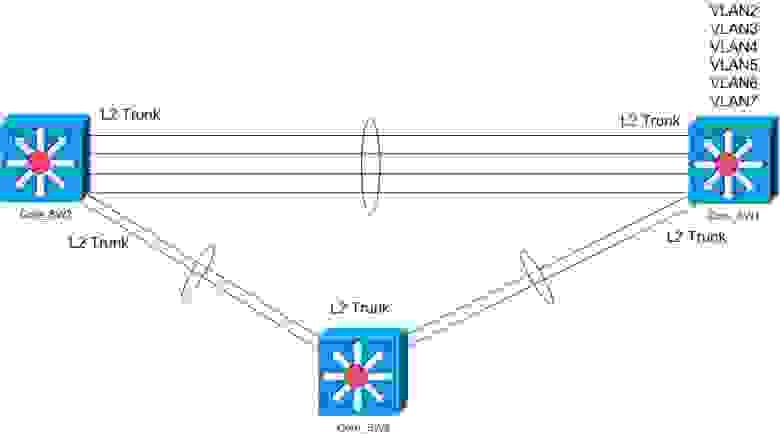
А после внедрения EIGRP получим такую схему. Три коммутатора ядра соединены между собой L3 линками, с помощью EIGRP динамически определяется наикратчайший маршрут, трафик балансируется между всеми линками. В общем используются все соединения, в отличии от того что было, где работали линии, незарубленные Spanning Tree.
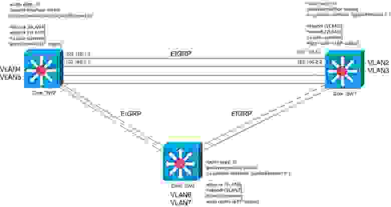
Работает EIGRP следующим образом. По L3 линку рассылаются hello-пакеты (с заданной периодичностью). После того как устройство получает ответ, оно устанавливает «соседские» отношения и начинает обмениваться информацией о подключенных к нему сетях. Когда все устройства увидят друг друга и установят соседские отношения, у каждого из них будет вся таблица маршрутизации сети. Стоит отметить следующее — если в течении hold-таймера от соседа не получен hello-пакет, он считается мертвым и его маршруты удаляются из таблицы маршрутизации.
Настройка
Необходимо задать IP-адреса для L3 интерфейсов. К слову, на маршрутизаторах интерфейсы и так L3, на коммутаторах с функцией маршрутизации же, интерфейсы по умолчанию L2. Чтобы сделать их L3 и задать IP, нужно ввести команду на интерфейсе:
no switchport
ip address [IP-адрес] [маска]
После настройки интерфейсов запускаем EIGRP
Cisco_2811_ons(config)#router eigrp [номер автономной системы]]
Cisco_2811_ons(config-router)#eigrp router-id [IP-адрес] /есть возможность задать IP-адрес, по которому это устройство будет идентифицироваться
Задаем сети(VLAN’ы), о которых будем рассказывать соседям:
Cisco_2811_ons(config-router)#network [сеть] [обратная маска]
Так же необходимо проанонсировать подсети L3 интерфейсов.
Зададим hello и hold таймеры (задается на интерфейсе и с обоих сторон значения должны совпадать):
Cisco_2811_ons(config-if)#ip hello-interval eigrp [номер автономной системы] [секунды]
Cisco_2811_ons(config-if)#ip hold-time eigrp [номер автономной системы]] [секунды]
Cisco рекомендует устанавливать hello-time 1 секунду, а hold-time 3 секунды.
Установим какие интерфейсы будет использовать EIGRP:
Cisco_2811_ons(config-router)#passive-interface default
Cisco_2811_ons(config-router)#no passive-interface [интерфейс порта] [слот/номер]
Это тот минимум команд, после которых EIGRP должен у вас заработать 
Траблшутинг
Чтобы посмотреть список соседей EIGRP:
Cisco_2811_ons#sh ip eigrp neighbors
Просмотр маршрутов:
Cisco_2811_ons#sh ip route
Cisco_2811_ons#sh ip route eigrp [номер автономной системы]
Дебаг:
Cisco_2811_ons#debug eigrp [номер автономной системы] [что смотреть]
Наверное все, что хотел написать… Хотелось достаточно кратко, т.к. думаю, что теорию голую можно и самостоятельно найти
Если есть вопросы — задайте, возможно что-то упустил из виду пока писал
P.S. В реальной сети отказались от внедрения EIGRP из-за наличия растянутых VLAN’ов. Если голосовой VLAN (IP-телефония) еще можно было побить и перенаправить DHCP-запросы с помощью команды ip helper-address, то с VLAN’ом разных микроконтроллеров и прочего (устройства хаотично разбросаны по всей территории объекта) + в него входят сервера, разбитие плохо представлялось, на него не пошли.
Так что товарищи, когда проектируете сети с нуля, думайте о будущем…
Описываются команды для конфигурирования и проверки работы протокола EIGRP;
- Планирование и базовая конфигурация EIGRP;
- Проверка работы;
- Использования команды passive-interface;
- Передача маршрута по умолчанию EIGRP;
- Суммирование.
Содержание
- 1 Планирование и базовая конфигурация EIGRP
- 1.1 Planning for Basic EIGRP
- 1.2 Требования и параметры
- 1.3 Базовая конфигурация
- 1.4 Пример базовой конфигурации
- 1.5 Другой пример базовой конфигурации
- 2 Проверка работы EIGRP
- 2.1 Проверка соседей
- 2.2 Проверка маршрутов
- 2.3 Проверка работы
- 2.3.1 show ip protocols
- 2.3.2 show ip eigrp interfaces
- 2.3.3 show ip eigrp topology
- 2.3.4 show ip eigrp traffic
- 2.3.5 debug eigrp packets
- 2.3.6 debug ip eigrp
- 2.4 Использование команды passive-interface
- 2.5 Распространение маршрута по умолчанию
- 2.6 Суммирование маршрутов в EIGRP
- 2.6.1 Конфигурирование суммирования в ручную
- 2.6.2 Проверка суммирования в ручную
- 2.6.3 Суммирование и Leak-Map
- 3 Ссылки
Планирование и базовая конфигурация EIGRP
Planning for Basic EIGRP
Сеть, показанная на рисунке, должна быть настроена на использование EIGRP
- Шаг 1. Определить требования к сети;
- Шаг 2. Собрать необходимые параметры;
- Шаг 3. Определить параметры маршрутизации EIGRP;
- Шаг 4. Сконфигурировать EIGRP;
- Шаг 5. Проверить конфигурацию.
Требования и параметры
R1 и R2 находятся в 110 AS, R3 — в нешней сети, не являющейся частью AS. Требования для базового EIGRP следующие:
- План адресации — ip адреса всех интерфейсов устройств;
- номера автономных систем EIGRP — маршрутизаторы в одном домене используют один номер AS. В примере 110;
- Интерфейсы, на которых запущен протокол, и участвующие в маршрутизации сети EIGRP — интерфейсы используются для обмена различными сообщениями между соседями. В
- Bandwidth интерфейсов — т.к. BW — часть метрики. Чтобы влиять на выбор пути. В примере актуальная пп — 512 кбит/сек.
В ранних IOS стандартная BW для всех serial-портов была T1 (1.544 мегабита). Сейчас варьируется от типа интерфейса.
Если стандартный параметр задержки на интерфейсе не отражает реальность, то можно воспользоваться командой
delay tens-of-microseconds.
Базовая конфигурация
В плане внедрения должны быть прописаны следующие задачи для базовой конфигурации EIGRP:
Шаг 1. — Включение EIGRP и назначение номера автономной системы:
R(config)#router eigrp <номер автономной системы>
Номер автономной системы должен быть одинаковым на всех маршрутизаторах, входящих в одну автономную систему.
Шаг 2. — Определение сетей, участвующих в маршрутизации EIGRP:
R(config)#network <IP-адрес сети> [<wildcard-маска>]
<IP-адрес сети> — непосредственно подключенная к маршрутизатору сеть. Этот параметр инструктирует EIGRP, что соединения, принадлежащие данной сети, должны объявляться соседям, а интерфейсы, назначенные данной сети, должны принимать EIGRP-объявления.
<wildcard-маска> — необязательный аргумент, уточняющий маску подсети. Маска подсети может быть введена как в wildcard-формате, так и в обычном. Например команды network 10.10.10.0 255.255.255.252 и network 10.10.10.0 0.0.0.3 идентичны.
Если опциональная wildcard-маска не используется, то процесс маршрутизации EIGRP будет работать со всеми напрямую подключёнными сетям, относящимися к классовой сети (А, В или С) и попытается установить соседские отношения через каждый такой интерфейс.
Шаг 3. — Определение полосы пропускания последовательных соединений (serial links). По умолчанию EIGRP рассматривает полосу пропускания последовательных соединений как 1544 кбит/с. В случае, если скорость соединения отлична от 1544 кбит/с, необходимо применить команду bandwidth на интерфейсе для правильного расчета метрик EIGRP:
R(config-if)#bandwidth <скорость>
<скорость> — аргумент, определяющий полосу пропускания интерфейса в кбит/с. Например, для соединения в 64 кбит/с команда будет: bandwidth 64.
Команда Bandwidth носит чисто информационный характер и реально никак не влияет на скорость соединения. Однако, стоит помнить, что она участвует в процессе расчёта метрик. Если соединения на самом деле медленнее, чем стандартное значение BW, это может привести к тому, что конвергенция не сможет произойти или обновления маршрутизации будут потеряны.
Для последовательных интерфейсов с инкапсуляцией PPP или HDLC нужно устанавливать bandwidth равным скорости линии. Для point-to-point интерфейсов Frame Relay — равным CIR (гарантированная скорость передачи). Для multipoint интерфейсов Frame Relay — равным сумме всех CIR, или, если виртуальные каналы (PVC) имеют различную скорость — равным минимальному CIR, умноженному на количество PVC.
BW полоса пропускания канала используется, например, протоколом TCP при повторной передаче.
Пример базовой конфигурации
Конфигурация R1 показана в примере 1 (Конфигурация R2 аналогична)
Пример 1
interface FastEthernet0/0
 ip address 172.16.1.1 255.255.255.0

interface Serial0/0/1
 bandwidth 512
 ip address 192.168.1.101 255.255.255.254

interface Serial0/0/2
 ip address 172.16.5.1 255.255.255.0

router eigrp 110
 network 172.16.1.0 0.0.0.255
 network 192.168.1.0
Из схемы и конфигурации R1 видно, что он анонсирует R2 маршрут к полной классовой сети 172.16.0.0, так как используется автосуммирование.
R1 не сконфигурирован для работы RIGRP на 172.16.5.0 (указана масска 0.0.0.255), поэтому он не пытается установить соседство с R3.
Другой пример базовой конфигурации
Рассмотрим начальную конфигурацию EIGRP для маршрутизатора A. Данный маршрутизатор, как и остальные, принадлежит автономной системе с номером 109. Непосредственно к нему подключены четыре подсети: 10.1.0.0, 10.4.0.0, 172.16.2.0, 172.16.7.0. Если не использовать wildcard-маску в объявлении сетей, то команды начальной конфигурации будут выглядеть так:
A(config)#router eigrp 109
A(config-router)#network 10.0.0.0
A(config-router)#network 172.16.2.0
Нам не нужно указывать точные IP-адреса подсетей. Если не используется wildcard-маска, маршрутизатор обнуляет хостовую часть IP-адреса подсети до границы класса. Другими словами, объявление всех подсетей 10.1.0.0, 10.4.0.0, 172.16.2.0, 172.16.7.0 привело бы к точно такому же результату, что и команды выше.
Wildcard-маска может использоваться для конкретизации интерфейсов и подсетей, участвующих в EIGRP. Например, представим, что маршрутизатор E является внешним, не входящим в автономную систему 109, и мы не желаем обмениваться с ним EIGRP-информацией. Это сэкономит полосу пропускания и процессорное время маршрутизатора. В этом случае команды начальной конфигурации будут выглядеть следующим образом:
A(config)#router eigrp 109
A(config-router)#network 10.1.0.0 0.0.255.255
A(config-router)#network 10.4.0.0 0.0.255.255
A(config-router)#network 172.16.2.0 0.0.0.255
Видно, что подсеть 172.16.7.0 не объявлена. Маршрутизатор A не устанавливает соседские отношения с маршрутизатором E, не посылает и не принимает EIGRP-пакеты через эту подсеть, и не рассказывает о ней своим соседям.
Проверка работы EIGRP
| Команда | Описание |
|---|---|
| show ip eigrp neighbors | выдаёт список соседей, обнаруженных EIGRP |
| show ip route | Показывает текущие записи в таблице маршрутизации для всех сконфигурированных протоколов маршрутизации. |
| show ip route eigrp | Показывает записи EIGRP в таблице маршрутизации |
| show ip protocols | Показывает параметры и текущий статус активных протоколов маршрутизации. Для EIGRP показывает номера AS, фильтрацию и redistribution numbers, соседей и информацию о дистанциях |
| show ip eigrp interfaces | Показывает информацию о задействованных EIGRP интерфейсах |
| show ip eigrp topology | Показывает топологическую таблицу EIGRP, статусы (active и passive) для маршрутов, число successor, FD для назначения. Внимание! Показываются только successor и feasible successor маршруты. Добавьте к команде all-links чтобы показать все маршруты. |
| show ip eigrp traffic | Показывает число полученных и отправленных пакетов EIGRP. Показывает статистику по hello-пакетам, обновлениям, запросам, ответам и ACK |
 Используйте команду debug с осторожностью! Может быть требовательна к ресурсам, что повлияет на работу сети.
 Вывод дебага имеет более высокий приоритет, чем другой сетевой трафик.
| Команда | Описание |
|---|---|
| debug eigrp packets | Отображает типы пакетов EIGRP, полученных и отправленных. Максимум 11 типов пакетов может быть выбрано для отдельного или группового отображения. |
| debug ip eigrp | Отображает всю доступную отладочную информацию EIGRP, касающуюся протокола IP. Отображает пакеты, которые отправлены или получены на интерфейсе. Т.к. команда генерирует много информации, используйте только, когда трафик в сети небольшой. |
| debug ip eigrp summary | Разрешает отладку процедур, связанных с обработкой суммарных маршрутов EIGRP |
| debug eigrp neighbors | Отображает процесс поиска соседей и содержание hello-пакетов |
Проверка соседей
Команда show ip eigrp neighbors отображает содержание таблицы соседей.
R1#show ip eigrp neighbors
IP-EIGRP neighbors for process 100
H   Address                 Interface       Hold Uptime   SRTT   RTO  Q   Seq
                                             (sec)         (ms)       Cnt Num
0   192.168.1.102           Se1/0          14 00:02:27     44    2280  0   3
- H (handle) — внутренний номер EIGRP-соседа. Данное поле заполняется по мере обнаружения соседей.
- Address — адрес сетевого уровня соседнего маршрутизатора.
- Interface — интерфейс, через который был обнаружен соседний маршрутизатор.
- Hold (hold time) — время в секундах, в течении которого маршрутизатор ждет EIGRP-пакет от соседа, прежде чем объявить его недоступным.
- Uptime — время продолжительности соседских отношений с данным маршрутизатором.
- SRTT (smoothed round-trip time — усредненная круговая задержка). Среднее время необходмое для отправки EIGRP-пакета и получения подтверждения.
- RTO (retrnsmisson timeout — таймер повторной передачи) — время в мс, в течении которого маршрутизатор ждет от соседа подтверждения получения пакета, прежде чем выслать пакет повторно. Когда маршрутизатор передает update-, query- или reply-пакет, он помещает копию этого пакета в очередь, которая затем используется для повторной отправки. RTO вычисляется на основе SRTT.
- Q Cnt (queue count) — число пакетов ожидающих в очереди. Если это значение постоянно поднимается выше 0, это указывает на наличие чрезмерной загрузки соединения.
- Seq Num — последовательный номер последнего update-, query- или reply-пакета, полученного от соседа. Используется для обнаружения нарушения порядка пакетов.
Детальную информацию можно получить командой show ip eigrp neighbors detail
R1#show ip eigrp neighbors detail
IP-EIGRP neighbors for process 110
H   Address                 Interface       Hold Uptime   SRTT   RTO   Q  Seq
                                                (sec)     (ms)        Cnt Num
0   192.168.1.102           Se0/0/1            14 00:17:27  0    4500  3   274
   Last startup serial 569
   Version 12.4/1.0, Retrans: 2, Retries: 2, Waiting for Init Ack
     Update seq 307 ser 29-569 Sent 8924 Init Sequenced
     Update seq 310 ser 570-573 Sequenced
     Update seq 312 ser 574-578 Sequenced
Здесь дополнительно указано:
- number of items a packet has been retransmitted (в примере 2);
- число попыток повторной передачи пекета (2);
- пакеты, ожидающие отправки (три);
- соседний маршрутизатор имеет IOS 12.4
- sequence номер (seq), увеличивающийся при каждом отправленном пакете-запросе, пакете-обновлении или пакете-ответе.
- ser — серийный номер, увеличивающийся при каждом изменении топологической таблицы.
Проверка маршрутов
show ip route eigrp
R1#show ip route eigrp
D    172.17.0.0/16 [90/40514560] via 192.168.1.102, 00:00:46, Serial1/0
     172.16.0.0/16 is variably subnetted, 2 subnets, 2 masks
D       172.16.0.0/16 is a summary, 00:01:18, Null0
     192.168.1.0/24 is variably subnetted, 2 subnets, 2 masks
D       192.168.1.0/24 is a summary, 00:43:00, Null0
Команда show ip route eigrp выводит EIGRP-маршруты в таблице маршрутизации IP. EIGRP поддерживает следующие типы маршрутов: internal (внутренний), external (внешний) и summary (суммарный). Маршрут EIGRP помечен буквой D. Внешние EIGRP-маршруты (за пределы локальной автономной системы) помечаются как D EX.
После адреса сети в квадратных скобках указана метрика. EIGRP-метрика равна возможному расстоянию FD маршрута в таблице топологии. Первое число (в примере 90) — это административная дистанция, которая используется для выбора наилучшего маршрута, если существует больше одного маршрута к одному месту назначения, найденные разными протоколами маршрутизации. Выигрывает протокол с меньшей административной дистанцией.
Внимание
Помните, что маршрутизаторы используют административную дистанцию только если хотя бы два одинаковых маршрута
к назначению (и маска и адрес). Например, маршрутизатор выберет RIP, а не EIGRP, если его маршрут более специфичный.
Следующее поле «via 192.168.1.102» показывает адрес соседнего маршрутизатора (next-hop), через который будут передаваться пакеты для сети 172.17.0.0/16. Next-hop адрес в таблице топологии — это адрес преемника (successor) для данного места назначения.
Каждый маршрут отсчитывает время (00:00:46) с того момента, как сеть была объявлена локальному (нашему) маршрутизатору. Маршрутизатор повторно рассылает маршрутную информацию только когда меняется neighbor adjacencies. Следующее поле содержит интерфейс (в примере Serial1/0) через который передаются пакеты для данного места назначения.
Таблица маршрутизации содержит маршруты через интерфейсы Null0. Эти маршруты называется суммарными и помещаются в таблицу маршрутизации, если включено автоматическое суммирование. Null0 — это непосредственно подключенный программный интерфейс. Если маршрутизатор получает пакет для неизвестной сети, являющейся частью суммарной сети, (172.16.3.5, например) то данный пакет передается на интерфейс Null0, как наиболее соответствующий суммарной сети 172.16.0.0/16. Проще говоря, маршрутизатор удаляет этот пакет, вместо того, чтобы послать его на шлюз последней надежды, что могло бы привести к появлению петли.
Проверка работы
show ip protocols
R1#show ip protocols
Routing Protocol is "eigrp 100"
  Outgoing update filter list for all interfaces is not set
  Incoming update filter list for all interfaces is not set
  Default networks flagged in outgoing updates
  Default networks accepted from incoming updates
  EIGRP metric weight K1=1, K2=0, K3=1, K4=0, K5=0
  EIGRP maximum hopcount 100
  EIGRP maximum metric variance 1
  Redistributing: eigrp 100
  EIGRP NSF-aware route hold timer is 240s
  Automatic network summarization is in effect
  Automatic address summarization:
    192.168.1.0/24 for FastEthernet0/0
       Summarizing with metric 40512000
    172.16.0.0/16 for Serial1/0
      Summarizing with metric 28160
  Maximum path: 4
  Routing for Networks:
    172.16.1.0/24
    192.168.1.0
  Routing Information Sources:
    Gateway         Distance      Last Update
    (this router)         90      01:02:26
    Gateway         Distance      Last Update
    192.168.1.102         90      01:01:57
  Distance: internal 90 external 170
Команда show ip protocols выводит информацию о протоколах маршрутизации запущенных на маршрутизаторе. Вывод показывает входящую и исходящую фильтрацию обновлений (входящих и исходящих) EIGRP, генерирует ли маршрутизатор или получает обновления о сети по умолчанию (wether EIGRP is generating a default network or receiving a default network in EIGRP updates).
Выводятся значения весовых коэффициентов EIGRP (K1 — K5), максимальное количество прыжков (hop), metric variance (отклонение метрики при балансировке нагрузки), включено ли автоматическое суммирование (automatic summarization) и максимальное количество маршрутов при балансировке (maximum path).
Два маршрутизатора должны иметь одинаковые значения параметров K для установления соседства!
Показаны сети, для которых включен EIGRP (Routing for Networks). Формат вывода сетей зависит от того, определена ли wildcard-маска при их объявлении. Для сети 172.16.1.0 была прописана wildcard-маска 0.0.0.255, на что указывает префикс подсети /24. В ином случае выводится адрес классовой сети.
Секция Routing Information Sources (источники информации о маршрутизации) содержит адреса соседних EIGRP-маршрутизаторов. Указаны два значения административной дистанции (Distance: internal 90 external 170): 90 — применяется для маршрутов внутри автономной системы, 170 — к внешним маршрутам, выходящих за границы автономной системы.
show ip eigrp interfaces
R1#show ip eigrp interfaces
IP-EIGRP interfaces for process 100

                        Xmit Queue   Mean   Pacing Time   Multicast    Pending
Interface        Peers  Un/Reliable  SRTT   Un/Reliable   Flow Timer   Routes
Fa0/0              0        0/0         0       0/1            0           0
Se1/0              1        0/0        41      10/380        544           0
Команда show ip eigrp interfaces выводит информацию об интерфейсах, настроенных для EIGRP. Вывод содержит следующие столбцы:
- Interface — имя интерфейса.
- Peers — количество соседей подключенных через данный интерфейс
- Xmit Queue Un/Reliable — число пакетов находящихся в очередях надежной (reliable) и ненадежной (unreliable) доставки.
- Mean SRTT — усредненная круговая(??) задержка в мс.
- Pacing Time Un/Reliable — шаговое время, используемое для определения того, когда EIGRP-пакеты должны быть переданы через интерфейс (для надёжных и ненадёжных пакетов).
- Multicast Flow Timer — максимальное число секунд, через которое маршрутизатор ожидает ACK-пакет после отправки многоадресного EIGRP-пакета, перед тем, как переключиться с мультикаста на юникаст.
- Pending Routes — число маршрутов в пакетах в очереди передачи, ожидающих отправки (number of routes in the packets in the retransmit queue waiting to be sent).
show ip eigrp topology
Отображает статусы DUAL и помогает решать возможные проблемы в его работе.
R1#show ip eigrp topology
IP-EIGRP Topology Table for AS(100)/ID(192.168.1.101)
Codes: P - Passive, A - Active, U - Update, Q - Query, R - Reply,
       r - reply Status, s - sia Status

P 192.168.1.96/27, 1 successors, FD is 40512000
        via Connected, Serial1/0
P 192.168.1.0/24, 1 successors, FD is 40512000
        via Summary (40512000/0), Null0
P 172.16.0.0/16, 1 successors, FD is 28160
        via Summary (28160/0), Null0
P 172.17.0.0/16, 1 successors, FD is 40514560
        via 192.168.1.102 (40514560/28160), Serial1/0
P 172.16.1.0/24, 1 successors, FD is 28160
        via Connected, FastEthernet0/0
Данная команда используется для проверки EIGRP-операций. Вывод показывает, что R1 имеет ID = 192.168.1.101 (максимальный IP-адрес активного интерфейса данного маршрутизатора (и loopback-интерфейсов, если они сконфигурированы), принадлежащего автономной системе с номером 100). Альтернативный способ — указать ID командой eigrp router-id ip-address (в этом случае, даже если есть и физ и/или loopback, в качестве ID будет использоваться указанный командой).
Записями служат места (сети) назначения, изученные протоколом EIGRP. Запись может иметь одно из следующих состояний (указано в первой колонке):
- P (Passive) — Сеть доступна и запись выложена в таблицу маршрутизации. Пассивный режим — нормальное состояние записи.
- A (Active) — Сеть не доступна в данный момент, запись не представлена в таблице маршрутизации. Active означает, что маршрутизатор разослал запросы о данной сети назначения.
- U (Update) — Сеть обновляется (показывает, что update-пакет был отправлен). Этот режим также применяется в случае, когда маршрутизатор ждет подтверждения ACK для update-пакета.
- Q (Query) — Разосланы query-пакеты для данной сети назначения. Этот режим также применяется в случае, когда маршрутизатор ждет подтверждения ACK для query-пакета.
- R (Reply) — Маршрутизатор генерирует (или создал) reply для данной сети. Показывает, что reply-пакет был отправлен. Этот режим также применяется в случае, когда маршрутизатор ждет подтверждения ACK для reply-пакета.
- r (Reply status) — Показывает флаг, установленный после того как ПО отправило query(запрос) и ожидает reply(ответ)
- s (Stuck-in-active status) — Застрял в активном режиме. EIGRP имеет проблемы сходимости для данной сети назначения.
Команда выводит количество преемников (что соответствует числу лучших маршрутов в сети, имеющих одинаковую стоимость) для каждой сети назначения (1 successors) и наименьшее FD (возможное расстояние). FD выводится также для каждого маршрута к сети назначения. Это значение расположено после IP-адреса соседа в формате FD/AD. Например, в примере к сети назначения 172.17.0.0/16 имеется маршрут через 192.168.1.102 с FD=40514560 и AD=28160.
show ip eigrp traffic
R1#show ip eigrp traffic
IP-EIGRP Traffic Statistics for AS 100
  Hellos sent/received: 4436/2166
  Updates sent/received: 8/8
  Queries sent/received: 1/0
  Replies sent/received: 0/1
  Acks sent/received: 3/2
  Input queue high water mark 2, 0 drops
  SIA-Queries sent/received: 0/0
  SIA-Replies sent/received: 0/0
  Hello Process ID: 131
  PDM Process ID: 130
Команда выводит количество различных переданных и принятых EIGRP-пакетов. Например, в примере R1 разослал 4436 и принял 2166 hello-пакетов. Отправил и получил по 8 обновлений. Отправил 1 и получил 0 запросов. Отправил 0 ответов и получил 1 ответ. Отправил 3 ACK, получил 2 ACK.
debug eigrp packets
Показывает передачу и прием пакетов протокола EIGRP.Например пакеты приветствия, обновления маршрутов, запросы или ответы на запрос.В пакетах используются номера последовательности и номера подтверждений используемые фирменным алгоритмом надежной доставки данных протокола EIGRP.
500px
В выводе показана нормальная передача и приём пакетов. Последовательной соединение HDLC p2p. Стандратный интервал hello 5 сек. Hello-пакеты рассылаются ненадёжным методом, т.к. Seq не увеличивается.
В данном выводе, когда R2 получает обновление от R1, появляется значение в поле seq. Seq 5/4 показывает, что R1 (192.168.1.101) отослал этот пакет с номером последовательности 5 маршрутизатору R2, а номер 4 был получен R1 от R2. R1 ожидает получить seq 5 в следующем надёжном пакете от R2.
R2 возвращает ACK пакет с Seq 0/5. ACK отправлен ненадёжным методом. Установлен neighbor unreable/reliable флаг (un/rel 1/0), что значит, что ACK был отправлен в ответ на reliable пакет.
Серийный номер (serno 9-9) отражает число изменений, которые два соседа обнаружили в их топологических таблицах. Seq увеличивается каждый раз при отправке запроса, обновления или ответа, тогда как серийный номер увеличивается при каждом изменений таблицы топологии. Одно обновление может содержать больше 100 сетей, например, если они все стали недоступными. Поэтому, если топологическая таблице имеет больше 100 изменений, серийный номер (serno) существенно возрастает, но seq увеличивается только на 1.
Результат вывода дебага на R2 при переводе интерфейса в shutdown R1 показан ниже.
500px
R1 отправляет запрос R2 чтобы определить, знает ли R2 маршрут к пропавшей сети. R2 отвечает ACK пакетом для подтверждения query-пакета — reliable-пакет должен быть подтверждём ACK-пакетом. R2 также отвечает на запрос ответом. Серийный номер 10-12 отражает колличество изменений в топологической таблице с момента начала соседских отношений между этими двумя маршрутизаторами EIGRP.
debug ip eigrp
Используется для проверки работы EIGRP. Показывает пакеты, которые получает и отправляет маршрутизатор.
Дописать 103 страница
Использование команды passive-interface
Бывают случаи, когда вы должны или хотите включить подсеть в команду network протокола маршрутизации, однако вы при этом не хотите, чтобы интерфейс, к которому подключена подсеть, участвовал в маршрутизации.
passive-interface {type number}| default — препятствует рассылке обновлений маршрутизации протокола маршрутизации через определённый интерфейс и установке соседства. В команде указывается или конкретный интерфейс, или параметром default все интерфейсы маршрутизатора.
Для EIGRP команда:
- Препятствует установлению соседских отношений через passive интерфейс;
- Останавливает применение полученных обновлений и их рассылку через этот интерфейс;
- Позволяет подсети на пассивном интерфейсе быть объявленной (to be announced) в процессе EIGRP.
При использовании команды passive-interface hello-сообщения не рассылаются через определённый интерфейс. С другими маршрутизаторами, достижимыми через интерфейс, соседство не формируется (т.к. процесс двухсторонний). Соответственно, нет соседства — нет другого трафика EIGRP.
Вспомните, что команда network определяется интерфейсы, через которые EIGRP будет пытаться установить соседство и сети, которые будут анонсированны соседям. Конфигурирование интерфейса как пассивного отключает только установление соседства. Маршрутизатор будет анонсировать сеть своим соседям.
R1#
router eigrp 110
 passive-interface FastEthernet0/0
network 172.16.1.0 0.0.0.255
network 192.168.1.0
R2#
router eigrp 110
 passive-interface FastEthernet0/0
 network 172.17.2.0 0.0.0.255
 network 192.168.1.0
Внимание!
EIGRP не установит соседство на пассивном интерфейсе даже если указать соседа на интерфейсе командой neighbor
Раньше, до IOS 12, админы конфигурили маршрутизацию для всех интерфейсов, а потом вручную отклчали их. Сейчас же можно перевести все интерфейсы в пассивное состояние (passive-interface default), а затем на нужных указать no passive-interface.
R1#
router eigrp 110
 passive-interface defaul
 passive-interface Serialt0/0/1
 network 172.16.1.0 0.0.0.255
 network 192.168.1.0
Для проверки работы EIGRP, при использовании пассивных интерфейсов, используются следующие команды:
- show ip eigrp neighbors — для того, чтобы узнать что отношения со всеми соседями установлены.
- show ip protocols — чтобы увидеть, какие интерфейсы пассивные. Например
R1#show ip protocols
Routing protocol is "eigrp 110"
<-- часть вывода отсуствует -->
Passive Interface(s):
   FastEthernet0/0
<-- часть вывода отсуствует -->
Команда passive-interface используется для управления объявлением информации маршрутизации. Данная команда включает
подавление обновлений маршрутов через некоторые интерфейсы, однако она разрешает проводить обмен обновлениями через другие
интерфейсы в обычном режиме.
В протоколах большинства маршрутов команда passive-interface ограничивает только исходящие объявления. Однако при
использовании протокола EIGRP (Усовершенствованный внутренний протокол маршрутизации шлюзов) результат немного
отличается. В этом документе показано, как команда passive-interface на EIGRP подавляет обмен hello-пакетами между двумя маршрутизаторами, что приводит к прекращению отношений соседства между ними. Это действие не только останавливает выдачу объявлений об обновлениях маршрутов, но также подавляет входящие обновления маршрутов. В этом документе также
рассматривается конфигурация, необходимая для разрешения подавления исходящих обновлений маршрутизации, а также для
возможности получения входящих обновлений маршрутизации от соседей.
Если в сети работает протокол EIGRP, команда passive-interface блокирует исходящие и входящие обновления маршрутизации,
поскольку результат команды приводит к остановке маршрутизатором отправки и приема hello-пакетов по интерфейсу.
При использовании команды passive-interface в EIGRP маршрутизатор не может формировать соседскую смежность в интерфейсе
либо получать или отправлять обновления маршрутов. Однако если необходимо подавление только исходящих обновлений
маршрутизации и продолжение приема входящих обновлений (при этом маршрутизаторы остаются соединенными с соседями), то
используйте команду distribute-list следующим образом:
R1(config)# access-list 20 deny any
...
R1(config)# router eigrp 1
R1(config-router)# no passive-interface serial 0
R1(config-router)# distribute-list 20 out serial 0
Распространение маршрута по умолчанию
Использование маршрутов по умолчанию сокращает таблицы маршрутизации на маршрутизаторах, получивших их. Например, маршрутизаторам в stub-сетях или на уровне доступа обычно не требуется знать все маршруты во всей сети. Вместо этого они могут использовать маршрут по умолчанию для пересылки трафика маршрутизаторам, имеющим более полные таблицы маршрутизации.
Вы можете создать маршрут по умолчанию (default route) EIGRP c помощью команды
ip route 0.0.0.0 0.0.0.0 { next-hop | interface [next-hop]}
Или, любая классовая сеть, находящаяся в таблице маршрутизации, может стать EIGRP маршрутом по умолчанию:
R(config)#ip default-network <адрес сети>
<адрес сети> — классовый IP-адрес сети по умолчанию.
Эта команда объявляет <адрес сети> как шлюз последней надежды (gateway of last resort), который маршрутизатор анонсирует другим маршрутизаторам с exterior flag set. Сеть по умолчанию должна быть доступна маршрутизатору, который использует эту команду, прежде чем он анонсирует её в качестве кандидата в маршруты по умолчанию другим EIGRP-маршрутизаторам. Чтобы сеть могла быть передана соседним EIGRP-маршрутизаторам, она должны быть объявлена в конструкции router eigrp <AS> (т.е. быть известной маршрутизаторам, быть в их таблицах) или в статическом маршруте, который будет распределен через EIGRP.
Внимание!
В EIGRP маршруты по умолчанию не могут быть прямо указаны (directly injected) (как они могут в OSPF с командой
default-information originate
Внимание!
Любой маршрут, находящийся в таблице маршрутизации, включая НЕ-EIGRP маршруты, может быть помечен как кандидат по
умолчанию.
Можно объявить более одной default network. Соседние маршрутизаторы используют метрику EIGRP для определения лучшего маршрута по умолчанию. Когда лучший маршрут по умолчанию выбран, маршрутизатор ставит GW of last resort… (When the best defaul route is selected, the router sets the gateway of last resort to the next-hop address of the selected candidate, unless the best candidate route is one of the router’s directly connected routers). Другие маршрутизаторы используют свой next-hop адрес для анонсирования сети как их стандартного маршрута (Other routers use their next-hop address to the advertised network as their default route).
На рисунке изображен маршрутизатор A, подключенный непосредственно к внешней сети 172.31.0.0. A объявляет 172.31.0.0 кандидатом в сети по умолчанию следующими командами:
A(config)#router eigrp 1
A(config-router)#network 10.0.0.0
A(config-router)#network 172.31.0.0 // обратить внимание, сеть перечислена в network
A(config-router)#exit
A(config)#ip default-network 172.31.0.0 //объявлена
Информация о сети по умолчанию передается маршрутизатору B, т.к. данная сеть объявлена в блоке router eigrp 1.
A#sh ip route
...
Gateway of last resort is not set

C*   172.31.0.0/16 is directly connected, Serail0/0/0
C    10.5.1.0/24 is directly connected, FastEthernet0/0
Заметим, что A не выбирает 172.31.0.0 шлюзом последней надежды. Команда ip default-network не имеет такого действия на локальный маршрутизатор.
B#sh ip route
...
Gateway of last resort is 192.168.1.1 to network 172.16.0.0

D*   172.16.0.0/16 [90/307200] via 192.168.1.1, 00:01:44, FastEthernet0/0
C    192.168.1.0/24 is directly connected, FastEthernet0/0
Маршрутизатор B помечает изученную сеть 172.16.0.0 в качестве кандидата в сеть по умолчанию (символ * в записи маршрута). B также устанавливает шлюзом последней надежды 10.5.1.1 (адрес маршрутизатора A) для достижения сети по молчанию 172.131.0.0.
Заметим, что EIGRP ведет себя отлично от RIP в отношении статических маршрутов по умолчанию, созданных командой route 0.0.0.0 0.0.0.0. Например, по умолчанию EIGRP не передает информацию о таких маршрутах соседям. Следующие команды показывают, как добиться того, чтобы маршруты 0.0.0.0 объявлялись соседям.
A(config)#ip route 0.0.0.0 0.0.0.0 172.16.0.2
A(config)#router eigrp 100
A(config-router)#network 0.0.0.0
Внимание!
При конфигурировании командой ip default-network создаётся статический маршрут. Однако IOS никак это событие не
отображает. Если вы хотите удалить default network, нужно использовать команду no ip route, а не команду
no ip default-network.
Суммирование маршрутов в EIGRP
Некоторые функции протокола EIGRP, такие как автосуммирование маршрутов на границе классовой сети, имеют характеристики дистанционно векторных и классовых протоколов. Традиционно, дистанционно векторные протоколы, относящиеся к классовым протоколам маршрутизации, должны суммировать на границах сети. Они не могут знать маску для сетей, которые напрямую не подключены, так как маски не содержатся в обновлениях маршрутизации.
Суммирование маршрутов на границе классовых сетей позволяет сокращать таблицы маршрутизации. Меньшие таблицы — меньший размер обновлений, меньшее использование ресурсов маршрутизатора. Дистанционно-векторные протоколы Cisco используют автосуммирование по умолчанию. В EIGRP автосуммирование может быть включено или отключено.
Неспособность создавать суммированные маршруты на произвольных границах классовой сети было недостатком дистанционно-векторных протоколов с момента их появления. В EIGRP добавили функциональность, позволяющую администраторам создавать один или несколько суммированных маршрутов в пределах сети на любой битовой границе (on any bit boundary), до тех пор пока более специфический маршрут существует в таблице маршрутизации. Когда после специфический маршрут из суммированного пропадает, суммированный маршрут удаляется из таблицы маршрутизации.
Важно знать, что для метрики суммированного маршрута используется минимальная метрика специфических
маршрутов.
Когда суммирование настроено на интерфейсе маршрутизатора, суммированный маршрут добавляется в таблицу маршрутизации с выходным интерфейсов null0 — напрямую подключённым программным интерфейсом. Использование интерфейса null0 при автосуммировании препятствует пересылке маршрутизатором трафика (он уничтожает пакеты, предназначенные для сетей, реальных маршрутов к которым у него нет) другим маршрутизаторам и предотвращает образование маршрутных петель.
Применение автосуммирования маршрутов сводится к тому, что некоторое количество специфичных маршрутов заменяется одним маршрутом, который охватывает все ip-адреса, относящиеся к подсетям в первоначальных маршрутах. Поэтому, к планированию выбора адресации нужно подойти серьёзно.
Число подсетей, которые могут быть представлены в суммированном маршруте, рассчитывается по формуле 2^n, где n — разница в числе битов между суммированной маской и маской подсети. Например, если суммированная маска содержит на 3 бита меньше, чем маска подсети 2^3 = 8 подсетей может быть агрегировано в одном маршруте.
Например, если сеть 10.0.0.0 разделена на подсети с префиксом /24 и некоторые из этих подсетей суммированны в блок 10.1.8.0/21. Разница между 24-21 = 3 бита. Таким образом 2^3 = 8 подсетей агрегируется. Суммируются подсети от 10.1.8.0/24 до 10.1.15.0/24.
При создании суммированных маршрутов администратору нужно определить IP адрес маршрута и его маску. Cisco IOS управляет деталями, такими как метрики, предотвращение петель и удаление суммированного маршрута из таблицы маршрутизации если нет ни одного более специфического маршрута, относящегося к суммированному.
Конфигурирование суммирования в ручную
В некоторых случаях вам может потребоваться отключить автоматическое суммирование в EIGRP, например, если у вас в сети есть разделённые подсети (discontigous subnets)
Внимание!
EIGRP маршрутизатор не выполняет автосуммирования сетей в которых он не участвует.
Для отключения автосуммирования использовать команду no auto-summary.
Для создание суммированного маршрута вручную на произвольной битовой границе, если существует более специфичный маршрут в таблице маршрутизации, использовать команду на интерфейсе
ip summary-address eigrp as-number mask | admin-distance,
где
- <as-number> — номер автономной системы EIGRP
- address — ip адрес, который будет анонсироваться как адрес суммированного маршрута. Адрес не должен совпадать с границами классовых сети А, В или С.
- mask — маска подсети, используемая для создания суммированного адреса.
- admin-distance — (Опционально) Административная дистанция. 0 — 255.
Вместо более специфичных маршрутов рассылается суммарный маршрут.
Преимущества суммирования:
- Таблицы маршрутизации меньше размером, при том, что сохраняется доступность всех destination.
- Сокращается диапазон рассылки Query (query scope): EIGRP Query останавливаются на маршрутизаторе, который имеет суммарный маршрут, включающий в себя подсеть, указанную в query, а не специфический маршрут.
- EIGRP поддерживает суммирование в любой точке сети.
- Суммарный маршрут имеет туже метрику, что и наилучший специфический маршрут, входящий в суммарный маршрут.
Минусы:
- Может служить причиной неоптимальной маршрутизации
- Пакеты будут дропаться при попадании в Null0
Для примера, на рисунке показана разделённая сеть 172.16.0.0. По умолчанию и А, и В суммируют маршрут на границе сети, использующей адреса классов. В результате С имеет два маршрута до 172.16.0.0 и будет выполнять балансировку трафика, что приведёт к некорректному поведению.
Поэтому необходимо отключить автосуммирование на А и В.
EIGRP маршрутизатор суммирует маршруты только для сетей, к которым он подключён (attached). Если сеть не суммирована автоматический на границе, как в примере с рисунком для А и В, т.к. автосуммирование отключено, то маршруты ко всем подсетям переносятся на маршрутизатор С. С не суммирует 172.16.1.0 и 172.16.2.0 подсети, потому что сеть 172.16.0.0 не его. Таким образом С отправляет инфу об этих сетях через WAN.
Тем не менее можно суммировать вручную маршрут для 172.16.0.0 на С
int s0/0/0
 ip address 192.168.4.2 255.255.255.0
 ip summary-address eigrp 1 172.16.0.0 255.255.0.0
Внимание!
Вы можете использовать ip summary-address eigrp as-number 0.0.0.0 0.0.0.0 команду для ввода маршрута по
умолчанию соседу, как альтернативным способом методам, описанным ранее в  Распространение маршрута по умолчанию.
При этом никаких других специфичных маршрутов анонсированно не будет.
Однако, автоматическое создание маршрута к null0 может стать проблемой в некоторых топологиях.
Если необходимо чтобы маршрут в null0 не помещался в таблицу маршрутизации, то необходимо указать AD = 255.
Проверка суммирования в ручную
Для проверки смотрите в таблицу маршрутизации.
Пример таблицы маршрутизации маршрутизатора С, имеющего маршруты к 172.16.1.0 и 172.16.2.0, разделённые подсети и суммированный маршрут к null0. Через s0/0/0 анонсируется только суммированный маршрут.
RouterC#show ip route
<часть вывода опущена>
Gateway of last resort is not set
      172.16.0.0/16 is variably subnetted, 3 subnets, 2 masks
D       172.16.0.0/16 is summary, 00:00:04, Null0
D       172.16.1.0/24 [90/156160] via 10.1.1.2, 00:00:04, Fastethernet0/0
D       172.16.2.0/24 [90/20640000] via 10.1.1.2, 00:00:04, Serial0/0/1
C     192.168.4.0/24 is derectly connected, Serial0/0/0
      10.0.0.0/8 is variably subnetted, 3 subnets, 2 masks
C       10.2.2.0/24 is derectly connected, Serial0/0/1
C       10.1.1.0/24 is derectly connected, FastEthernet0/0
D       10.0.0.0/8 is a summary, 00:00:05, Null0
Для ручного суммирования, суммированный маршрут анонсируется только если компонент суммированного маршрута (более специфическая запись, представленная в суммированном) присутствует в таблице маршрутизации.
Суммирование и Leak-Map
Если вы выполняете суммирование в ручную, но при этом вам необходимо анонсировать и специфические маршруты соседям, то можно сделать это, используя leak-map.
Если настроен Leak Map и:
- Он ссылается на несуществующий route-map — анонсируется суммарный маршрут, а более специфичные нет (they are suppressed);
- Если route-map существует, но он ссылается на несуществующий ACL, то и суммарный маршрут, и специфичные маршруты анонсируются;
- Если ACL существует, то он определяет маршруты, которые будут анонсироваться в дополнение (вместе с) суммарному маршруту.
To configure the Leak Map just attach a route-map to the «eigrp summary» command:
R2(config-if)#ip summary-address eigrp 100 2.2.4.0 255.255.252.0 leak-map ROUTE_MAP
Пример:
Пусть есть следующая топология
R1----------------R2-------------------R3
R1, R2, R3: AS 100
R1 has 5 loopbacks:
- 1.1.1.1/32
- 1.1.1.2/32
- 1.1.1.3/32
- 1.1.1.4/32
- 1.1.1.5/32
R1#show run | begin router eigrp 100
router eigrp 100
network 1.1.1.1 0.0.0.0
network 1.1.1.2 0.0.0.0
network 1.1.1.3 0.0.0.0
network 1.1.1.4 0.0.0.0
network 1.1.1.5 0.0.0.0
network 100.1.12.1 0.0.0.0
no auto-summary
eigrp router-id 1.1.1.1
R2#show run | begin router eigrp 100
router eigrp 100
network 100.1.12.2 0.0.0.0
network 100.1.23.2 0.0.0.0
no auto-summary
eigrp router-id 2.2.2.2
R3#show run | begin router eigrp 100
router eigrp 100
network 100.1.23.3 0.0.0.0
no auto-summary
eigrp router-id 3.3.3.3
R1#show ip route eigrp
     100.0.0.0/24 is subnetted, 2 subnets
D       100.1.23.0 [90/2681856] via 100.1.12.2, 00:03:18, Serial1/0
R2#show ip route eigrp
     1.0.0.0/32 is subnetted, 5 subnets
D       1.1.1.1 [90/2297856] via 100.1.12.1, 00:02:30, Serial1/0
D       1.1.1.3 [90/2297856] via 100.1.12.1, 00:02:30, Serial1/0
D       1.1.1.2 [90/2297856] via 100.1.12.1, 00:02:30, Serial1/0
D       1.1.1.5 [90/2297856] via 100.1.12.1, 00:02:30, Serial1/0
D       1.1.1.4 [90/2297856] via 100.1.12.1, 00:02:30, Serial1/0
R3#show ip route eigrp
    1.0.0.0/32 is subnetted, 5 subnets
D       1.1.1.1 [90/2809856] via 100.1.23.2, 00:02:42, Serial1/1
D       1.1.1.3 [90/2809856] via 100.1.23.2, 00:02:42, Serial1/1
D       1.1.1.2 [90/2809856] via 100.1.23.2, 00:02:42, Serial1/1
D       1.1.1.5 [90/2809856] via 100.1.23.2, 00:02:42, Serial1/1
D       1.1.1.4 [90/2809856] via 100.1.23.2, 00:02:42, Serial1/1
     100.0.0.0/24 is subnetted, 2 subnets
D       100.1.12.0 [90/2681856] via 100.1.23.2, 00:03:50, Serial1/1
Замечания:
- Автосуммирование отключено
- Суммирование в ручную ещё не настроено.
Настраиваем суммирование на R2 по направлению к R3:
R2(config-router)#int ser1/1
R2(config-if)#ip summary-address eigrp 100 1.1.1.0 255.255.255.248
R2(config-if)#
*Jul  5 14:37:27.143: %DUAL-5-NBRCHANGE: IP-EIGRP(0) 100: Neighbor 100.1.23.3 (Serial1/1) is resync: summary configured
R2(config-if)#
R2#show ip route eigrp
    1.0.0.0/8 is variably subnetted, 6 subnets, 2 masks
D       1.1.1.1/32 [90/2297856] via 100.1.12.1, 00:05:41, Serial1/0
D       1.1.1.0/29 is a summary, 00:01:07, Null0
D       1.1.1.3/32 [90/2297856] via 100.1.12.1, 00:05:41, Serial1/0
D       1.1.1.2/32 [90/2297856] via 100.1.12.1, 00:05:41, Serial1/0
D       1.1.1.5/32 [90/2297856] via 100.1.12.1, 00:05:41, Serial1/0
D       1.1.1.4/32 [90/2297856] via 100.1.12.1, 00:05:41, Serial1/0
R3#
*Jul  5 14:37:25.703: %DUAL-5-NBRCHANGE: IP-EIGRP(0) 100: Neighbor 100.1.23.2 (Serial1/1) is resync: peer graceful-restart
R3#
R3#show ip route eigrp
    1.0.0.0/29 is subnetted, 1 subnets
D       1.1.1.0 [90/2809856] via 100.1.23.2, 00:00:11, Serial1/1
     100.0.0.0/24 is subnetted, 2 subnets
D       100.1.12.0 [90/2681856] via 100.1.23.2, 00:05:53, Serial1/1
R3#
Замечания:
- Суммирование настроено на R2
- R3 получает суммированный маршрут
- Теперь R3 хочет получать 1.1.1.1/32 вместе с суммарный маршрутом
- Настроим leak-map на R2, чтобы маршрут 1.1.1.3/32 попал на R3
R2(config)#ip prefix-list LEAK permit 1.1.1.1/32
R2(config)#
R2(config)#route-map LEAK-MAP
R2(config-route-map)#match ip address prefix-list LEAK
R2(config-route-map)#int ser1/1
R2(config-if)#ip summary-address eigrp 100 1.1.1.0 255.255.255.248 leak-map LEAK-MAP
R2(config-if)#
*Jul  5 14:54:08.327: %DUAL-5-NBRCHANGE: IP-EIGRP(0) 100: Neighbor 100.1.23.3 (Serial1/1) is resync: summary configured
R2(config-if)#
R3#
*Jul  5 14:54:06.895: %DUAL-5-NBRCHANGE: IP-EIGRP(0) 100: Neighbor 100.1.23.2 (Serial1/1) is resync: peer graceful-restart
R3#
R3#show ip route eigrp
    1.0.0.0/8 is variably subnetted, 2 subnets, 2 masks
D       1.1.1.1/32 [90/2809856] via 100.1.23.2, 00:03:08, Serial1/1
D       1.1.1.0/29 [90/2809856] via 100.1.23.2, 00:19:49, Serial1/1
     100.0.0.0/24 is subnetted, 2 subnets
D       100.1.12.0 [90/2681856] via 100.1.23.2, 00:25:31, Serial1/1
R3#
Теперь у R3 есть 1.1.1.1/32.
Ссылки
Автосуммирование маршрутов в EIGRP
Enhanced Interior Gateway Routing Protocol (EIGRP) — это протокол маршрутизации, разработанный компанией Cisco Systems. EIGRP предоставляет возможности автоматического обнаружения сетевых узлов, автоматического конфигурирования маршрутов и автоматического обнаружения соседних маршрутизаторов. В этой статье мы рассмотрим пошаговое руководство по настройке EIGRP на маршрутизаторах Cisco.
EIGRP является одним из наиболее популярных протоколов маршрутизации и широко применяется в сетях Cisco. Он обеспечивает более высокую производительность, надежность и масштабируемость по сравнению с другими протоколами маршрутизации. Его особенности включают быструю сходимость сети, поддержку переменных метрик маршрута и возможность работы с различными видами сетевых протоколов (IP, IPX, AppleTalk).
Настройка EIGRP на маршрутизаторах Cisco включает в себя несколько шагов. Сначала необходимо включить EIGRP на маршрутизаторах и настроить соответствующие сетевые интерфейсы. Затем необходимо настроить параметры маршрутизации, такие как номер автономной системы (AS), дистанцию административных расстояний (AD) и команды рассылки маршрутов. После этого маршрутизаторы начнут обмениваться информацией о маршрутах и обновлять таблицы маршрутизации. В конечном итоге мы получим работающую сеть, основанную на EIGRP.
Важно отметить, что настройка EIGRP требует некоторых знаний и опыта в области маршрутизации и сетевых протоколов. Рекомендуется проводить настройку EIGRP в тестовой среде или под руководством опытного специалиста. Перед началом настройки EIGRP рекомендуется также убедиться, что маршрутизаторы Cisco поддерживают EIGRP и имеют достаточные ресурсы для его работы.
Содержание
- Основные понятия EIGRP
- Шаг 1: Создание EIGRP процесса
- Шаг 2: Настройка интерфейсов
- Шаг 3: Настройка соседей
- Шаг 4: Проверка настроек
Основные понятия EIGRP
Основные понятия, которые необходимо знать о протоколе EIGRP:
- AS (Autonomous System) — это независимая автономная система, в которой используется протокол маршрутизации EIGRP. Каждая автономная система имеет уникальный номер, называемый AS-номером, который используется для идентификации системы.
- Neighbor (сосед) — это устройство, подключенное к сети EIGRP и обменивающееся сообщениями с другими соседними устройствами. Соседи могут обмениваться информацией о маршрутах и состоянии сети.
- Routing table (таблица маршрутизации) — это таблица, содержащая информацию о доступных маршрутах в сети EIGRP. Она используется для принятия решений о передаче данных.
- Metric (метрика) — это значение, используемое для определения наилучшего маршрута в сети. EIGRP использует метрику, называемую «общей стоимостью», для выбора оптимального пути.
- Feasible Successor (допустимый преемник) — это альтернативный путь к некоторому маршруту, который может быть использован, если основной путь становится недоступным. EIGRP поддерживает допустимых преемников, чтобы обеспечить непрерывность соединения.
Эти основные понятия являются ключевыми для понимания работы EIGRP. Понимание их значений и связей между ними поможет в настройке и управлении протоколом EIGRP на сетевых устройствах Cisco.
Шаг 1: Создание EIGRP процесса
Например, чтобы создать процесс EIGRP с идентификатором 10, введите следующую команду:
Router(config)# router eigrp 10
После этого вы находитесь в режиме конфигурации процесса EIGRP и можете настраивать его параметры.
Примечание: Если вы хотите использовать сразу несколько процессов EIGRP на маршрутизаторе, просто повторите этот шаг для каждого процесса, указывая разные идентификаторы.
Шаг 2: Настройка интерфейсов
После настройки основных параметров EIGRP необходимо настроить интерфейсы на маршрутизаторах.
1. Подключитесь к маршрутизатору с помощью удобного терминального эмулятора или программы для доступа по SSH.
2. Откройте режим глобальной конфигурации с помощью команды configure terminal.
3. Перейдите в режим настройки интерфейса командой interface <название интерфейса>. Замените <название интерфейса> на название интерфейса, который вы хотите настроить, например, GigabitEthernet0/0.
4. Введите команду ip address <IP-адрес> <маска подсети> для назначения IP-адреса и маски подсети интерфейсу. Замените <IP-адрес> на желаемый IP-адрес, а <маска подсети> на соответствующую маску подсети.
5. Введите команду no shutdown, чтобы активировать интерфейс.
6. Для дальнейшей настройки EIGRP на данном интерфейсе введите команду ip hello-interval eigrp <AS-номер> <интервал обновления>. Замените <AS-номер> на номер вашей автономной системы EIGRP, а <интервал обновления> на требуемый интервал обновления в секундах.
7. Повторите процедуру для каждого интерфейса, который вы хотите использовать с протоколом EIGRP.
Шаг 3: Настройка соседей
После настройки основных параметров EIGRP, необходимо настроить соседство между роутерами, чтобы они обменивались маршрутной информацией. Для этого устанавливаются EIGRP соседские отношения между роутерами, которые находятся в одной сети и имеют общую автономную систему (AS).
Для настройки соседства EIGRP необходимо выполнить следующие шаги:
1. Выберите идентификатор автономной системы (AS) для EIGRP на каждом роутере, например, AS 100.
2. Настройте соседство EIGRP на интерфейсах, находящихся в одной сети и имеющих одинаковый номер автономной системы (AS). Для этого используйте команду router eigrp <идентификатор AS> и команду network <адрес сети> для каждого интерфейса, который должен быть частью EIGRP.
Например, если роутеры R1 и R2 находятся в одной сети 192.168.1.0/24 и имеют общую автономную систему AS 100, настроим соседство между ними следующим образом:
R1(config)#router eigrp 100
R1(config-router)#network 192.168.1.0
R2(config)#router eigrp 100
R2(config-router)#network 192.168.1.0
3. Проверьте статус соседства EIGRP с помощью команды show ip eigrp neighbors на каждом роутере. Если соседство установлено успешно, вы увидите информацию о соседях EIGRP.
4. Повторите шаги 2-3 для всех пар роутеров, между которыми должно быть установлено соседство EIGRP. Убедитесь, что все роутеры, которые должны быть соседями, настроены правильно и имеют общую автономную систему (AS).
Продолжайте настраивать EIGRP на Cisco, выполняя следующие шаги.
Шаг 4: Проверка настроек
После того, как вы завершили настройку EIGRP на своих устройствах Cisco, важно проверить корректность настроек. Ваша сеть должна работать без сбоев и обеспечивать стабильную передачу данных.
Для проверки настроек можно использовать следующие команды:
- Проверьте, что протокол EIGRP активен на каждом устройстве с помощью команды
show ip protocols. Убедитесь, что код маршрутизации равен EIGRP. - Используйте команду
show ip eigrp neighbors, чтобы увидеть список соседних устройств EIGRP. Установите, что все устройства имеют правильные соседние отношения. - Проверьте таблицу маршрутизации с помощью команды
show ip route. Убедитесь, что все маршруты EIGRP отображаются и имеют правильные метрики. - Протестируйте связность с помощью команды
ping. Пингуйте различные устройства в сети, чтобы убедиться, что пакеты успешно доставляются.
Если вы обнаружите какие-либо проблемы, вернитесь к предыдущим шагам и повторите настройку роутеров. Если все работает должным образом, значит настройка EIGRP на вашей сети была выполнена успешно.
Не забудьте сохранить конфигурацию на каждом устройстве, чтобы сохранить внесенные изменения:
copy running-config startup-config
Теперь вы можете наслаждаться преимуществами использования EIGRP в вашей сети Cisco.
The functions of a dynamic routing protocol are the same as a static routing protocol. If the destination is unreachable in from a point of routing then the other path can be created to reach the destination. To learn about EIGRP refer to EIGRP fundamentals.
Steps to Configure and Verify EIGRP in Cisco Packet Tracer :
Step 1: First, open the cisco packet tracer desktop and select the devices given below:
| S.NO | Device | Model Name | Qty. |
|---|---|---|---|
| 1. | pc | pc | 4 |
| 2. | switch | PT-Switch | 2 |
| 3. | router | PT-Router | 2 |
IP Addressing Table:
| S.NO | Device | IPv4 Address | Subnet Mask | Default Gateway |
|---|---|---|---|---|
| 1. | pc0 | 192.168.0.2 | 255.255.255.0 | 192.168.0.1 |
| 2. | pc1 | 192.168.0.3 | 255.255.255.0 | 192.168.0.1 |
| 3. | pc2 | 172.168.0.2 | 255.255.255.0 | 172.168.0.1 |
| 4. | pc3 | 172.168.0.3 | 255.255.255.0 | 172.168.0.1 |
- Then, create a network topology as shown below the image.
- Use an Automatic connecting cable to connect the devices with others.
Step 2: Configure the PCs (hosts) with IPv4 address and Subnet Mask according to the IP addressing table given above.
- To assign an IP address in PC1, click on PC1.
- Then, go to desktop and then IP configuration and there you will IPv4 configuration.
- Fill IPv4 address and subnet mask.
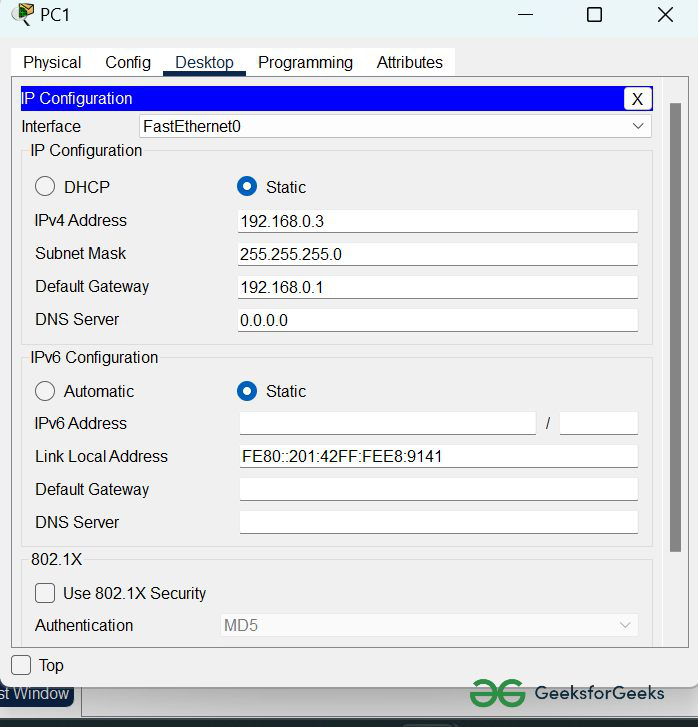
2. Assigning IP address using the ipconfig command.
- We can also assign an IP address with the help of a command.
- Go to the command terminal of the PC.
- Then, type ipconfig <IPv4 address><subnet mask><default gateway>(if needed)
Example: ipconfig 192.168.0.3 255.255.255.0 192.168.0.1
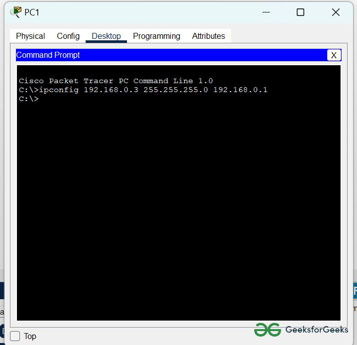
- Repeat the same procedure with other PCs to configure them thoroughly.
Step 3: Configure router with IP address and subnet mask.
IP Addressing Table Router:
| S.NO | Device | Interface | IPv4 Address | Subnet Mask |
|---|---|---|---|---|
| 1. | router0 | FastEthernet0/0 | 192.168.0.1 | 255.255.255.0 |
| Serial2/0 | 10.0.0.1 | 255.0.0.0 | ||
| 2. | router1 | FastEthernet0/0 | 172.168.0.1 | 255.255.0.0 |
| Serial2/0 | 10.0.0.2 | 255.0.0.0 |
- To assign an IP address in router0, click on router0.
- Then, go to config and then Interfaces.
- Now, configure the IP address in FastEthernet and serial ports according to IP addressing Table.
- Add IPv4 address and subnet mask.
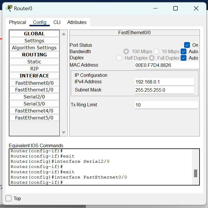
- Repeat the same procedure with other routers to configure them thoroughly.
Step 4: After configuring all of the devices we need to configure EIGRP protocols to the routers.
- First, click on router0 then Go to CLI.
- Then type the commands and IP information given below.
CLI command : router eigrp 10
network <network id>
Protocols for router0
Router(config)#router eigrp 10
Router(config-router)#network 192.168.0.0
Router(config-router)#network 10.0.0.0
Protocols for router0
Router(config)#router eigrp 10
Router(config-router)#network 172.168.0.0
Router(config-router)#network 10.0.0.0
Step 5: Verifying the network by pinging the IP address of any PC. We will use the ping command to do so.
- First, click on PC0 then Go to the command prompt
- Then type ping <IP address of targeted node>
- As we can see in the below image we are getting replies which means the connection is working very fine
Example: ping 172.168.0.2
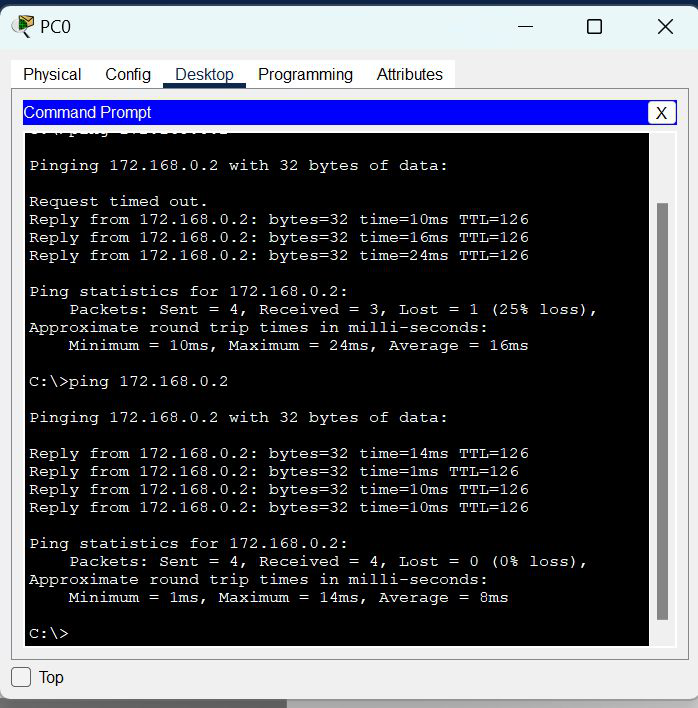
- A simulation of the experiment is given below we are sending PDU from PC0 to PC2 and PC1 to PC3:
Last Updated :
22 Jun, 2022
Like Article
Save Article