Введение
CRC (Cyclic Redundancy Check) – это метод обнаружения ошибок, используемый для проверки целостности переданных данных. Ошибки CRC могут возникать на портах устройств сети и могут иметь различные причины. В данной статье мы рассмотрим основные причины и предложим методы их решения.
Причины появления CRC ошибок на порту
-
Электромагнитные помехи: Наличие сильных электромагнитных полей вблизи порта устройства может привести к возникновению искажений сигнала и, следовательно, к появлению CRC ошибок.
-
Неисправности оборудования: Ошибки в работе физического уровня порта, такие как повреждения кабелей или неисправности сетевого адаптера, могут вызывать ошибки CRC.
-
Конфликты между устройствами: Когда два или более устройства пытаются передавать данные через один порт одновременно, возникают коллизии данных. Это может привести к появлению CRC ошибок.
-
Проблемы с протоколами: Некорректная конфигурация или несовместимость между сетевым оборудованием, работающим на разных протоколах, может вызывать ошибки CRC.
Методы решения проблем с CRC ошибками на порту
-
Проверка и замена кабелей: Проверьте кабели на наличие повреждений или несовместимости с используемыми устройствами. Замените поврежденные или несовместимые кабели, чтобы устранить ошибки CRC.
-
Проверка физического состояния порта: Проверьте физическое состояние порта, включая разъемы и контакты. Если обнаружена неисправность, замените сетевой адаптер или проведите ремонт порта.
-
Проверка наличия проблем с электромагнитными помехами: Поместите устройства подальше от источников электромагнитных помех, таких как электропровода или другие электронные устройства. Также можно воспользоваться экранированными кабелями для снижения влияния помех.
-
Обновление и настройка сетевого оборудования: Проверьте наличие обновленных драйверов и прошивок для сетевого оборудования. Выполните настройку сетевых параметров, таких как скорость передачи или дуплексный режим, в соответствии с требованиями вашей сети.
-
Проверка наличия конфликтов сетевых устройств: Проверьте, нет ли конфликтов IP-адресов или адресов MAC между устройствами в вашей сети. Измените адреса для устранения конфликтов.
-
Проверка протоколов и конфигурации: Проверьте наличие несовместимостей протоколов или настроек сетевого оборудования. Установите совместимые протоколы и выполните необходимые настройки.
Заключение
CRC ошибки на порту могут быть вызваны различными причинами, включая электромагнитные помехи, неисправности оборудования, конфликты между устройствами и проблемы с протоколами. Однако, с помощью правильного анализа и принятия соответствующих мер, эти ошибки могут быть успешно решены. Помните, что проведение регулярного технического обслуживания и выполнение рекомендаций по настройке сетевого оборудования поможет предотвратить возникновение CRC ошибок на порту.
CRC ошибка на порту означает, что произошло повреждение данных в кадре при передаче информации. При передаче данных в сети, каждый кадр имеет поле контрольной последовательности кадра (FCS), которая содержит значение циклического избыточного кода (CRC), вычисленное на основе битовой комбинации кадра. Это значение CRC используется для проверки целостности данных при их передаче.
- Что такое ошибки CRC
- Как исправить ошибку в данных CRC
- Что значит CRC
- Как работает CRC
- Полезные советы и выводы
Что такое ошибки CRC
Ошибка CRC означает, что при передаче данных произошло искажение информации, которое может привести к неправильному чтению или обработке данных. Контрольная сумма, вычисленная как CRC, позволяет определить, были ли данные повреждены в процессе передачи. Однако, важно отметить, что наличие правильной контрольной суммы не гарантирует полной достоверности передачи информации.
Как исправить ошибку в данных CRC
Для исправления ошибки в данных CRC можно воспользоваться утилитой CHKDSK в операционной системе Windows. CHKDSK сканирует и исправляет повреждения файловой системы и плохие сектора на устройстве, которые могут быть причиной ошибки CRC данных.
Что значит CRC
CRC (Cyclic Redundancy Check) или циклический избыточный код, является алгоритмом нахождения контрольной суммы, который используется для проверки целостности данных. Он основан на математических свойствах циклического кода и является практическим приложением помехоустойчивого кодирования.
Как работает CRC
Алгоритм CRC использует все биты сообщения для вычисления контрольной суммы. Если хотя бы один бит исходного сообщения изменится при передаче данных, контрольная сумма также изменится. Это позволяет однозначно определить, произошло ли искажение исходного сообщения при передаче или нет. Важно отметить, что изменение контрольной суммы может быть значительным при изменении всего одного бита, что делает алгоритм CRC эффективным для обнаружения ошибок при передаче данных.
Полезные советы и выводы
- При возникновении ошибки CRC на порту, следует принять меры для исправления поврежденных данных. Утилита CHKDSK в Windows может быть полезным инструментом для исправления ошибок CRC на устройстве.
- Важно понимать, что наличие правильной контрольной суммы CRC не гарантирует полной достоверности передачи информации. Для обеспечения надежности передачи данных могут использоваться дополнительные методы, такие как повторная передача данных или применение других алгоритмов проверки целостности.
- Алгоритм CRC основан на математических свойствах циклического кода, которые обеспечивают высокую эффективность обнаружения ошибок при передаче данных. При этом следует помнить, что CRC не предотвращает ошибки, а только обнаруживает их.
- Для обеспечения надежности передачи данных рекомендуется использовать несколько методов проверки целостности, включая CRC, а также применять механизмы повторной передачи и контроля ошибок.
- В случае продолжающихся ошибок CRC на порту следует обратиться к специалистам сети для более глубокого анализа и исправления проблемы.
Таким образом, ошибка CRC на порту является признаком повреждения данных в кадре при передаче информации. Для исправления подобных ошибок можно использовать утилиты, такие как CHKDSK, и применять дополнительные методы проверки целостности данных для обеспечения надежности передачи. Соблюдение рекомендаций и использование соответствующих мер предосторожности поможет минимизировать возникновение ошибок CRC и обеспечить стабильность и надежность работы сети.
Как узнать IP-адрес вашего роутера
Чтобы узнать IP-адрес вашего роутера, вам необходимо открыть «Командную строку» на компьютере. Для этого нажмите клавишу «Win + R» и введите «cmd», затем нажмите «Enter». В открывшемся окне командной строки введите команду «ipconfig» и нажмите «Enter». После этого на экране появится информация о сетевых подключениях.
Взгляните на раздел «Основной шлюз». Рядом с этим пунктом будет указан IP-адрес вашего роутера. Обычно он имеет вид «192.168.X.X», где X — это числа от 0 до 255. Ваш конкретный адрес может отличаться от примера.
После того, как вы узнали IP-адрес роутера, вы можете использовать его для доступа к настройкам роутера или для других целей, таких как проверка подключения или настройка безопасности сети.
Что означают лампочки на коммутаторе
Лампочки на коммутаторе имеют свои специфические значения. Первая лампочка, с надписью «Link/Act», отвечает за проверку соединения компьютера с портом коммутатора и определение активности сети на этом порту. Если лампочка горит, значит, соединение установлено и порт активен. Вторая лампочка, с надписью «FDX/Col», загорается в случае, если порт поддерживает полнодуплексный режим работы, то есть передачу данных в оба направления одновременно. Если порт работает в полнодуплексном режиме, лампочка будет гореть. Если же установлен полудуплексный режим работы, то есть передача данных только в одном направлении за раз, лампочка будет выключена. Таким образом, эти две лампочки на коммутаторе позволяют оператору сразу определить статус и режим работы порта.
Как узнать какой у меня IP-адрес
Чтобы узнать свой IP-адрес, необходимо выполнить несколько простых шагов. В начале нажмите комбинацию клавиш Win + R на клавиатуре. После этого появится окно «Выполнить». Введите в поле команду «cmd» (без кавычек) и нажмите кнопку «ОК». Теперь откроется окно «Командная строка». Введите команду «ipconfig» и нажмите клавишу Enter. После этого появится информация обо всех подключенных сетевых адаптерах. Найдите раздел «Адаптер беспроводной локальной сети Беспроводная сеть» и найдите IP-адрес, который будет отображен рядом с информацией «IPv4-адрес». Это и будет ваш IP-адрес. Теперь вы знаете, как узнать свой IP-адрес с помощью командной строки. Это может быть полезно, например, для настройки сетевого оборудования или подключения к удаленному серверу.
Как узнать IP адрес интерфейса Cisco
Для получения сведений об IP-адресе интерфейса Cisco необходимо выполнить команду show ip interface brief в командной строке (CLI). После выполнения данной команды будет выведен список всех портов и интерфейсов устройства, их текущее состояние и соответствующие IP-адреса.
Этот способ особенно полезен при работе с коммутатором или маршрутизатором Cisco в среде Packet Tracer, так как он позволяет быстро получить необходимую информацию о сетевых настройках интерфейсов.
Для выполнения команды show ip interface brief нужно зайти в режим конфигурации устройства и ввести данную команду в командной строке. После этого на экране появится таблица, содержащая IP-адреса интерфейсов и их состояние.
Этот метод позволяет значительно ускорить процесс настройки и решения сетевых проблем на устройствах Cisco.
Introduction
This document describes details surrounding Cyclic Redundancy Check (CRC) errors observed on interface counters and statistics of Cisco Nexus switches.
Prerequisites
Requirements
Cisco recommends that you understand the basics of Ethernet switching and the Cisco NX-OS Command Line Interface (CLI). For more information, refer to one of these applicable documents:
- Cisco Nexus 9000 NX-OS Fundamentals Configuration Guide, Release 10.2(x)
- Cisco Nexus 9000 Series NX-OS Fundamentals Configuration Guide, Release 9.3(x)
- Cisco Nexus 9000 Series NX-OS Fundamentals Configuration Guide, Release 9.2(x)
- Cisco Nexus 9000 Series NX-OS Fundamentals Configuration Guide, Release 7.x
- Troubleshooting Ethernet
Components Used
The information in this document is based on these software and hardware versions:
- Nexus 9000 series switches starting from NX-OS software release 9.3(8)
- Nexus 3000 series switches starting from NX-OS software release 9.3(8)
The information in this document was created from devices in a specific lab environment. All of the devices used in this document started with a cleared (default) configuration. If your network is live, ensure that you understand the potential impact of any command.
The information in this document was created from the devices in a specific lab environment. All of the devices used in this document started with a cleared (default) configuration. If your network is live, ensure that you understand the potential impact of any command.
Background Information
This document describes details surrounding Cyclic Redundancy Check (CRC) errors observed on interface counters on Cisco Nexus series switches. This document describes what a CRC is, how it is used in the Frame Check Sequence (FCS) field of Ethernet frames, how CRC errors manifest on Nexus switches, how CRC errors interact in Store-and-Forward switching and Cut-Through switching scenarios, the most likely root causes of CRC errors, and how to troubleshoot and resolve CRC errors.
Applicable Hardware
The information in this document is applicable to all Cisco Nexus Series switches. Some of the information in this document can also be applicable to other Cisco routing and switching platforms, such as Cisco Catalyst routers and switches.
CRC Definition
A CRC is an error detection mechanism commonly used in computer and storage networks to identify data changed or corrupted during transmission. When a device connected to the network needs to transmit data, the device runs a computation algorithm based on cyclic codes against the data that results in a fixed-length number. This fixed-length number is called the CRC value, but colloquially, it is often called the CRC for short. This CRC value is appended to the data and transmitted through the network towards another device. This remote device runs the same cyclic code algorithm against the data and compares the resulting value with the CRC appended to the data. If both values match, then the remote device assumes the data was transmitted across the network without being corrupted. If the values do not match, then the remote device assumes the data was corrupted during transmission across the network. This corrupted data cannot be trusted and is discarded.
CRCs are used for error detection across multiple computer networking technologies, such as Ethernet (both wired and wireless variants), Token Ring, Asynchronous Transfer Mode (ATM), and Frame Relay. Ethernet frames have a 32-bit Frame Check Sequence (FCS) field at the end of the frame (immediately after the payload of the frame) where a 32-bit CRC value is inserted.
For example, consider a scenario where two hosts named Host-A and Host-B are directly connected to each other through their Network Interface Cards (NICs). Host-A needs to send the sentence “This is an example” to Host-B over the network. Host-A crafts an Ethernet frame destined to Host-B with a payload of “This is an example” and calculates that the CRC value of the frame is a hexadecimal value of 0xABCD. Host-A inserts the CRC value of 0xABCD into the FCS field of the Ethernet frame, then transmits the Ethernet frame out of Host-A’s NIC towards Host-B.
When Host-B receives this frame, it will calculate the CRC value of the frame with the use of the exact same algorithm as Host-A. Host-B calculates that the CRC value of the frame is a hexadecimal value of 0xABCD, which indicates to Host-B that the Ethernet frame was not corrupted while the frame was transmitted to Host-B.
CRC Error Definition
A CRC error occurs when a device (either a network device or a host connected to the network) receives an Ethernet frame with a CRC value in the FCS field of the frame that does not match the CRC value calculated by the device for the frame.
This concept is best demonstrated through an example. Consider a scenario where two hosts named Host-A and Host-B are directly connected to each other through their Network Interface Cards (NICs). Host-A needs to send the sentence “This is an example” to Host-B over the network. Host-A crafts an Ethernet frame destined to Host-B with a payload of “This is an example” and calculates that the CRC value of the frame is the hexadecimal value 0xABCD. Host-A inserts the CRC value of 0xABCD into the FCS field of the Ethernet frame, then transmits the Ethernet frame out of Host-A’s NIC towards Host-B.
However, damage on the physical media connecting Host-A to Host-B corrupts the contents of the frame such that the sentence within the frame changes to “This was an example” instead of the desired payload of “This is an example”.
When Host-B receives this frame, it will calculate the CRC value of the frame including the corrupted payload. Host-B calculates that the CRC value of the frame is a hexadecimal value of 0xDEAD, which is different from the 0xABCD CRC value within the FCS field of the Ethernet frame. This difference in CRC values tells Host-B that the Ethernet frame was corrupted while the frame was transmitted to Host-B. As a result, Host-B cannot trust the contents of this Ethernet frame, so it will drop it. Host-B will usually increment some sort of error counter on its Network Interface Card (NIC) as well, such as the “input errors”, “CRC errors”, or “RX errors” counters.
Common Symptoms of CRC Errors
CRC errors typically manifest themselves in one of two ways:
- Incrementing or non-zero error counters on interfaces of network-connected devices.
- Packet/Frame loss for traffic traversing the network due to network-connected devices dropping corrupted frames.
These errors manifest themselves in slightly different ways depending on the device you are working with. These sub-sections go into detail for each type of device.
Received Errors on Windows Hosts
CRC errors on Windows hosts typically manifest as a non-zero Received Errors counter displayed in the output of the netstat -e command from the Command Prompt. An example of a non-zero Received Errors counter from the Command Prompt of a Windows host is here:
>netstat -e
Interface StatisticsReceived Sent
Bytes 1116139893 3374201234
Unicast packets 101276400 49751195
Non-unicast packets 0 0
Discards 0 0
Errors 47294 0
Unknown protocols 0
The NIC and its respective driver must support accounting of CRC errors received by the NIC in order for the number of Received Errors reported by the netstat -e command to be accurate. Most modern NICs and their respective drivers support accurate accounting of CRC errors received by the NIC.
RX Errors on Linux Hosts
CRC errors on Linux hosts typically manifest as a non-zero “RX errors” counter displayed in the output of the ifconfig command. An example of a non-zero RX errors counter from a Linux host is here:
$ ifconfig eth0
eth0: flags=4163<UP,BROADCAST,RUNNING,MULTICAST>  mtu 1500
        inet 192.0.2.10  netmask 255.255.255.128  broadcast 192.0.2.255
        inet6 fe80::10  prefixlen 64  scopeid 0x20<link>
        ether 08:62:66:be:48:9b  txqueuelen 1000  (Ethernet)
        RX packets 591511682  bytes 214790684016 (200.0 GiB)
        RX errors 478920  dropped 0  overruns 0  frame 0
        TX packets 85495109  bytes 288004112030 (268.2 GiB)
        TX errors 0  dropped 0 overruns 0  carrier 0  collisions 0
CRC errors on Linux hosts can also manifest as a non-zero “RX errors” counter displayed in the output of ip -s link show command. An example of a non-zero RX errors counter from a Linux host is here:
$ ip -s link show eth0
2: eth0: <BROADCAST,MULTICAST,UP,LOWER_UP> mtu 1500 qdisc mq state UP mode DEFAULT group default qlen 1000
    link/ether 08:62:66:84:8f:6d brd ff:ff:ff:ff:ff:ff
    RX: bytes  packets  errors  dropped overrun mcast
    32246366102 444908978 478920       647     0       419445867
    TX: bytes  packets  errors  dropped carrier collsns
    3352693923 30185715 0       0       0       0
    altname enp11s0
The NIC and its respective driver must support accounting of CRC errors received by the NIC in order for the number of RX Errors reported by the ifconfig or ip -s link show commands to be accurate. Most modern NICs and their respective drivers support accurate accounting of CRC errors received by the NIC.
CRC Errors on Network Devices
Network devices operate in one of two forwarding modes — Store-and-Forward forwarding mode, and Cut-Through forwarding mode. The way a network device handles a received CRC error differs depending on its forwarding modes. The subsections here will describe the specific behavior for each forwarding mode.
Input Errors on Store-and-Forward Network Devices
When a network device operating in a Store-and-Forward forwarding mode receives a frame, the network device will buffer the entire frame (“Store”) before you validate the frame’s CRC value, make a forwarding decision on the frame, and transmit the frame out of an interface (“Forward”). Therefore, when a network device operating in a Store-and-Forward forwarding mode receives a corrupted frame with an incorrect CRC value on a specific interface, it will drop the frame and increment the “Input Errors” counter on the interface.
In other words, corrupt Ethernet frames are not forwarded by network devices operating in a Store-and-Forward forwarding mode; they are dropped on ingress.
Cisco Nexus 7000 and 7700 Series switches operate in a Store-and-Forward forwarding mode. An example of a non-zero Input Errors counter and a non-zero CRC/FCS counter from a Nexus 7000 or 7700 Series switch is here:
switch# show interface
<snip>
Ethernet1/1 is up
  RX
    241052345 unicast packets  5236252 multicast packets  5 broadcast packets
    245794858 input packets  17901276787 bytes
    0 jumbo packets  0 storm suppression packets
    0 runts  0 giants  579204 CRC/FCS  0 no buffer
    579204 input error  0 short frame  0 overrun   0 underrun  0 ignored
    0 watchdog  0 bad etype drop  0 bad proto drop  0 if down drop
    0 input with dribble  0 input discard
    0 Rx pause
CRC errors can also manifest themselves as a non-zero “FCS-Err” counter in the output of show interface counters errors. The «Rcv-Err» counter in the output of this command will also have a non-zero value, which is the sum of all input errors (CRC or otherwise) received by the interface. An example of this is shown here:
switch# show interface counters errors
<snip>
--------------------------------------------------------------------------------
Port          Align-Err    FCS-Err   Xmit-Err    Rcv-Err  UnderSize OutDiscards
--------------------------------------------------------------------------------
Eth1/1                0     579204          0     579204          0           0
Input and Output Errors on Cut-Through Network Devices
When a network device operating in a Cut-Through forwarding mode starts to receive a frame, the network device will make a forwarding decision on the frame’s header and begin transmitting the frame out of an interface as soon as it receives enough of the frame to make a valid forwarding decision. As frame and packet headers are at the beginning of the frame, this forwarding decision is usually made before the payload of the frame is received.
The FCS field of an Ethernet frame is at the end of the frame, immediately after the frame’s payload. Therefore, a network device operating in a Cut-Through forwarding mode will already have started transmitting the frame out of another interface by the time it can calculate the CRC of the frame. If the CRC calculated by the network device for the frame does not match the CRC value present in the FCS field, that means the network device forwarded a corrupted frame into the network. When this happens, the network device will increment two counters:
- The “Input Errors” counter on the interface where the corrupted frame was originally received.
- The “Output Errors” counter on all interfaces where the corrupted frame was transmitted. For unicast traffic, this will typically be a single interface – however, for broadcast, multicast, or unknown unicast traffic, this could be one or more interfaces.
An example of this is shown here, where the output of the show interface command indicates multiple corrupted frames were received on Ethernet1/1 of the network device and transmitted out of Ethernet1/2 due to the Cut-Through forwarding mode of the network device:
switch# show interface
<snip>
Ethernet1/1 is up
RX
46739903 unicast packets 29596632 multicast packets 0 broadcast packets
76336535 input packets 6743810714 bytes
15 jumbo packets 0 storm suppression bytes
0 runts 0 giants 47294 CRC 0 no buffer
47294 input error 0 short frame 0 overrun 0 underrun 0 ignored
0 watchdog 0 bad etype drop 0 bad proto drop 0 if down drop
0 input with dribble 0 input discard
0 Rx pauseEthernet1/2 is up
TX
46091721 unicast packets 2852390 multicast packets 102619 broadcast packets
49046730 output packets 3859955290 bytes
50230 jumbo packets
47294 output error 0 collision 0 deferred 0 late collision
0 lost carrier 0 no carrier 0 babble 0 output discard
0 Tx pause
CRC errors can also manifest themselves as a non-zero “FCS-Err” counter on the ingress interface and non-zero «Xmit-Err» counters on egress interfaces in the output of show interface counters errors. The «Rcv-Err» counter on the ingress interface in the output of this command will also have a non-zero value, which is the sum of all input errors (CRC or otherwise) received by the interface. An example of this is shown here:
switch# show interface counters errors
<snip>
--------------------------------------------------------------------------------
Port          Align-Err    FCS-Err   Xmit-Err    Rcv-Err  UnderSize OutDiscards
--------------------------------------------------------------------------------
Eth1/1                0      47294          0      47294          0           0
Eth1/2                0          0      47294          0          0           0
The network device will also modify the CRC value in the frame’s FCS field in a specific manner that signifies to upstream network devices that this frame is corrupt. This behavior is known as “stomping” the CRC. The precise manner in which the CRC is modified varies from one platform to another, but generally, it involves inverting the current CRC value present in the frame’s FCS field. An example of this is here:
Original CRC: 0xABCD (1010101111001101)
Stomped CRC:  0x5432 (0101010000110010)
As a result of this behavior, network devices operating in a Cut-Through forwarding mode can propagate a corrupt frame throughout a network. If a network consists of multiple network devices operating in a Cut-Through forwarding mode, a single corrupt frame can cause input error and output error counters to increment on multiple network devices within your network.
Trace and Isolate CRC Errors
The first step in order to identify and resolve the root cause of CRC errors is isolating the source of the CRC errors to a specific link between two devices within your network. One device connected to this link will have an interface output errors counter with a value of zero or is not incrementing, while the other device connected to this link will have a non-zero or incrementing interface input errors counter. This suggests that traffic egresses the interface of one device intact is corrupted at the time of the transmission to the remote device, and is counted as an input error by the ingress interface of the other device on the link.
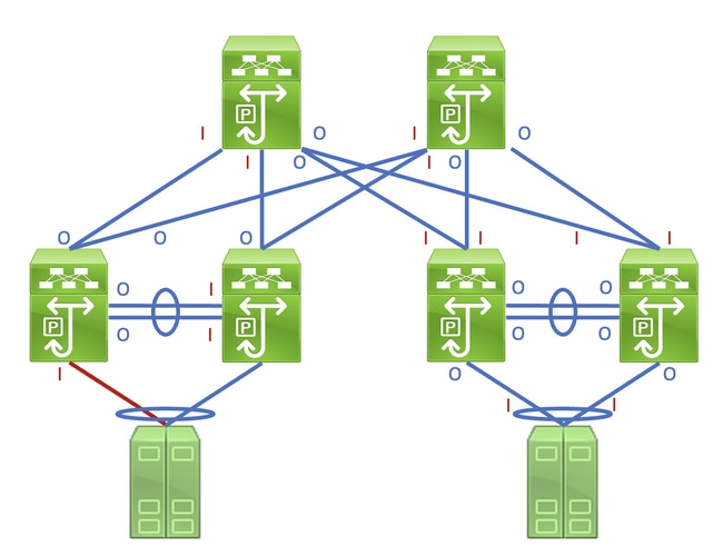
Identifying this link in a network consisting of network devices operating in a Store-and-Forward forwarding mode is a straightforward task. However, identifying this link in a network consisting of network devices operating in a Cut-Through forwarding mode is more difficult, as many network devices will have non-zero input and output error counters. An example of this phenomenon can be seen in the topology here, where the link highlighted in red is damaged such that traffic traversing the link is corrupted. Interfaces labeled with a red «I» indicate interfaces that could have non-zero input errors, while interfaces labeled with a blue «O» indicate interfaces that could have non-zero output errors.
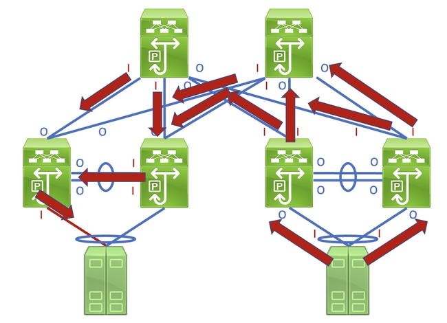
Identifying the faulty link requires you to recursively trace the «path» corrupted frames follow in the network through non-zero input and output error counters, with non-zero input errors pointing upstream towards the damaged link in the network. This is demonstrated in the diagram here.
A detailed process for tracing and identifying a damaged link is best demonstrated through an example. Consider the topology here:
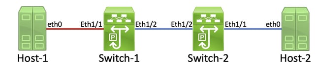
In this topology, interface Ethernet1/1 of a Nexus switch named Switch-1 is connected to a host named Host-1 through Host-1’s Network Interface Card (NIC) eth0. Interface Ethernet1/2 of Switch-1 is connected to a second Nexus switch, named Switch-2, through Switch-2’s interface Ethernet1/2. Interface Ethernet1/1 of Switch-2 is connected to a host named Host-2 through Host-2’s NIC eth0.
The link between Host-1 and Switch-1 through Switch-1’s Ethernet1/1 interface is damaged, causing traffic that traverses the link to be intermittently corrupted. However, we do not yet know that this link is damaged. We must trace the path the corrupted frames leave in the network through non-zero or incrementing input and output error counters to locate the damaged link in this network.
In this example, Host-2’s NIC reports that it is receiving CRC errors.
Host-2$ ip -s link show eth0
2: eth0: <BROADCAST,MULTICAST,UP,LOWER_UP> mtu 1500 qdisc mq state UP mode DEFAULT group default qlen 1000
    link/ether 00:50:56:84:8f:6d brd ff:ff:ff:ff:ff:ff
    RX: bytes  packets  errors  dropped overrun mcast
    32246366102 444908978 478920       647     0       419445867
    TX: bytes  packets  errors  dropped carrier collsns
    3352693923 30185715 0       0       0       0
    altname enp11s0
You know that Host-2’s NIC connects to Switch-2 via interface Ethernet1/1. You can confirm that interface Ethernet1/1 has a non-zero output errors counter with the show interface command.
Switch-2# show interface
<snip>
Ethernet1/1 is up
admin state is up, Dedicated Interface
    RX
      30184570 unicast packets  872 multicast packets  273 broadcast packets
      30185715 input packets  3352693923 bytes
      0 jumbo packets  0 storm suppression bytes
      0 runts  0 giants 0 CRC  0 no buffer
      0 input error  0 short frame  0 overrun   0 underrun  0 ignored
      0 watchdog  0 bad etype drop  0 bad proto drop  0 if down drop
      0 input with dribble  0 input discard
      0 Rx pause
    TX
      444907944 unicast packets  932 multicast packets  102 broadcast packets
      444908978 output packets  32246366102 bytes
      0 jumbo packets
      478920 output error  0 collision  0 deferred  0 late collision
      0 lost carrier  0 no carrier  0 babble  0 output discard
      0 Tx pause
Since the output errors counter of interface Ethernet1/1 is non-zero, there is most likely another interface of Switch-2 that has a non-zero input errors counter. You can use the show interface counters errors non-zero command in order to identify if any interfaces of Switch-2 have a non-zero input errors counter.
Switch-2# show interface counters errors non-zero
<snip>
--------------------------------------------------------------------------------
Port          Align-Err    FCS-Err   Xmit-Err    Rcv-Err  UnderSize OutDiscards
--------------------------------------------------------------------------------
Eth1/1                0          0     478920          0          0           0
Eth1/2                0     478920          0     478920          0           0

--------------------------------------------------------------------------------
Port         Single-Col  Multi-Col   Late-Col  Exces-Col  Carri-Sen       Runts
--------------------------------------------------------------------------------

--------------------------------------------------------------------------------
Port          Giants SQETest-Err Deferred-Tx IntMacTx-Er IntMacRx-Er Symbol-Err
--------------------------------------------------------------------------------

--------------------------------------------------------------------------------
Port         InDiscards
--------------------------------------------------------------------------------
You can see that Ethernet1/2 of Switch-2 has a non-zero input errors counter. This suggests that Switch-2 receives corrupted traffic on this interface. You can confirm which device is connected to Ethernet1/2 of Switch-2 through the Cisco Discovery Protocol (CDP) or Link Local Discovery Protocol (LLDP) features. An example of this is shown here with the show cdp neighbors command.
Switch-2# show cdp neighbors
<snip>
    Capability Codes: R - Router, T - Trans-Bridge, B - Source-Route-Bridge
    S - Switch, H - Host, I - IGMP, r - Repeater,
    V - VoIP-Phone, D - Remotely-Managed-Device,
    s - Supports-STP-Dispute

Device-ID          Local Intrfce  Hldtme Capability  Platform      Port ID
Switch-1(FDO12345678)
                    Eth1/2         125    R S I s   N9K-C93180YC- Eth1/2
You now know that Switch-2 is receiving corrupted traffic on its Ethernet1/2 interface from Switch-1’s Ethernet1/2 interface, but you do not yet know whether the link between Switch-1’s Ethernet1/2 and Switch-2’s Ethernet1/2 is damaged and causes the corruption, or if Switch-1 is a cut-through switch forwarding corrupted traffic it receives. You must log into Switch-1 to verify this.
You can confirm Switch-1’s Ethernet1/2 interface has a non-zero output errors counter with the show interfaces command.
Switch-1# show interface
<snip>
Ethernet1/2 is up
admin state is up, Dedicated Interface
    RX
      30581666 unicast packets  178 multicast packets  931 broadcast packets
      30582775 input packets  3352693923 bytes
      0 jumbo packets  0 storm suppression bytes
      0 runts  0 giants 0 CRC  0 no buffer
      0 input error  0 short frame  0 overrun   0 underrun  0 ignored
      0 watchdog  0 bad etype drop  0 bad proto drop  0 if down drop
      0 input with dribble  0 input discard
      0 Rx pause
    TX
      454301132 unicast packets  734 multicast packets  72 broadcast packets
      454301938 output packets  32246366102 bytes
      0 jumbo packets
      478920 output error  0 collision  0 deferred  0 late collision
      0 lost carrier  0 no carrier  0 babble  0 output discard
      0 Tx pause
You can see that Ethernet1/2 of Switch-1 has a non-zero output errors counter. This suggests that the link between Switch-1’s Ethernet1/2 and Switch-2’s Ethernet1/2 is not damaged — instead, Switch-1 is a cut-through switch forwarding corrupted traffic it receives on some other interface. As previously demonstrated with Switch-2, you can use the show interface counters errors non-zero command in order to identify if any interfaces of Switch-1 have a non-zero input errors counter.
Switch-1# show interface counters errors non-zero
<snip>
--------------------------------------------------------------------------------
Port          Align-Err    FCS-Err   Xmit-Err    Rcv-Err  UnderSize OutDiscards
--------------------------------------------------------------------------------
Eth1/1                0     478920          0     478920          0           0
Eth1/2                0          0     478920          0          0           0

--------------------------------------------------------------------------------
Port         Single-Col  Multi-Col   Late-Col  Exces-Col  Carri-Sen       Runts
--------------------------------------------------------------------------------

--------------------------------------------------------------------------------
Port          Giants SQETest-Err Deferred-Tx IntMacTx-Er IntMacRx-Er Symbol-Err
--------------------------------------------------------------------------------

--------------------------------------------------------------------------------
Port         InDiscards
--------------------------------------------------------------------------------
You can see that Ethernet1/1 of Switch-1 has a non-zero input errors counter. This suggests that Switch-1 is receiving corrupted traffic on this interface. We know that this interface connects to Host-1’s eth0 NIC. We can review Host-1’s eth0 NIC interface statistics to confirm whether Host-1 sends corrupted frames out of this interface.
Host-1$ ip -s link show eth0
2: eth0: <BROADCAST,MULTICAST,UP,LOWER_UP> mtu 1500 qdisc mq state UP mode DEFAULT group default qlen 1000
    link/ether 00:50:56:84:8f:6d brd ff:ff:ff:ff:ff:ff
    RX: bytes  packets  errors  dropped overrun mcast
    73146816142 423112898 0       0     0       437368817
    TX: bytes  packets  errors  dropped carrier collsns
    3312398924 37942624 0       0       0       0
    altname enp11s0
The eth0 NIC statistics of Host-1 suggest the host is not transmitting corrupted traffic. This suggests that the link between Host-1’s eth0 and Switch-1’s Ethernet1/1 is damaged and is the source of this traffic corruption. Further troubleshooting will need to be performed on this link to identify the faulty component causing this corruption and replace it.
Root Causes of CRC Errors
The most common root cause of CRC errors is a damaged or malfunctioning component of a physical link between two devices. Examples include:
- Failing or damaged physical medium (copper or fiber) or Direct Attach Cables (DACs).
- Failing or damaged transceivers/optics.
- Failing or damaged patch panel ports.
- Faulty network device hardware (including specific ports, line card Application-Specific Integrated Circuits [ASICs], Media Access Controls [MACs], fabric modules, etc.),
- Malfunctioning network interface card inserted in a host.
It is also possible for one or more misconfigured devices to inadvertently causes CRC errors within a network. One example of this is a Maximum Transmission Unit (MTU) configuration mismatch between two or more devices within the network causing large packets to be incorrectly truncated. Identifying and resolving this configuration issue can correct CRC errors within a network as well.
Resolve CRC Errors
You can identify the specific malfunctioning component through a process of elimination:
- Replace the physical medium (either copper or fiber) or DAC with a known-good physical medium of the same type.
- Replace the transceiver inserted in one device’s interface with a known-good transceiver of the same model. If this does not resolve the CRC errors, replace the transceiver inserted in the other device’s interface with a known-good transceiver of the same model.
- If any patch panels are used as part of the damaged link, move the link to a known-good port on the patch panel. Alternatively, eliminate the patch panel as a potential root cause by connecting the link without using the patch panel if possible.
- Move the damaged link to a different, known-good port on each device. You will need to test multiple different ports to isolate a MAC, ASIC, or line card failure.
- If the damaged link involves a host, move the link to a different NIC on the host. Alternatively, connect the damaged link to a known-good host to isolate a failure of the host’s NIC.
If the malfunctioning component is a Cisco product (such as a Cisco network device or transceiver) that is covered by an active support contract, you can open a support case with Cisco TAC detailing your troubleshooting to have the malfunctioning component replaced through a Return Material Authorization (RMA).
Related Information
- Nexus 9000 Cloud Scale ASIC CRC Identification & Tracing Procedure
- Technical Support & Documentation — Cisco Systems
Introduction to CRC
Bit errors (0 changed to 1 or 1 changed to 0) may occur in transmitted data due to transmission media faults or external interference, causing incorrect data on the receive end. To resolve this problem, the receive end needs to perform error detection on the received data and accepts the data only when it is correct.
There are many error detection methods, such as parity check, checksum check, and CRC check. Their implementation is similar: The transmit end calculates a check code for data using a certain algorithm, and sends the check code and data to the receive end. The receive end performs the same calculation to check whether the data changes.
CRC was first proposed by W. Wesley Peterson, a mathematician and computer scientist, in 1961. CRC has advantages over other error detection methods in terms of speed, cost, and correctness. Therefore, CRC has become the most commonly used error detection method in the computer information and communications fields. For example, a standard Ethernet frame ends with a 4-byte frame check sequence (FCS) for error detection.

Ethernet frame format
How Is CRC Calculation Implemented?
CRC enables the transmit end to append an R-bit check code to the K-bit data to be sent, generate a new frame, and send the frame to the receive end. When receiving the new frame, the receive end checks whether the received data is correct based on the received data and check code.

Example of data and check code
The check code needs to ensure that the generated new frame is divisible by a specific number that is selected by both the transmit end and receive end (modulo-2 division). The receive end divides the received new frame by the selected divisor. Because a number has been added before the data frame is sent to remove the remainder, there should be no remainder. If there is a remainder, an error occurs during the transmission of the frame.
An R-bit check code is appended to the K-bit data, and the entire code length becomes N bits. This type of code is also referred to as (N,K) code. For a given (N,K) code, it can be proved that there is a polynomial g(x) whose highest power is N–K=R, and an R-bit check code can be generated based on g(x). The algorithm is based on the GF(2) polynomial arithmetic, as shown in the following figure.

CRC calculation formula
g(x) is called the generator polynomial of the check code. Different CRC generator polynomials have different error detection capabilities. To use an R-bit check code, the power of the generator polynomial must be R. The following lists some common standard polynomials.

Commonly used generator polynomials
The value of these polynomials is the divisor of modulo 2 division. Obtaining and checking the check code by using the divisor consist of the following steps:
- Before communication, the transmit end and receive end agree on a divisor P, that is, the value of a polynomial. The length of P should be R+1 bits.
- The transmit end first appends R zeros to the original K-bit data, which is equivalent to shifting the original data to the left by R bits.
- Then, a modulo-2 division operation (an XOR operation) is performed to divide the (K+R)-bit number obtained after the addition of zeros by P, and cyclic calculation is performed until an order of a remainder is less than R. The remainder is the check code. If the check code length is less than R bits, zeros are prepended to it to ensure that the length is R bits.
- The transmit end appends the R-bit check code to the original data and sends the data to the receive end.
- When receiving the data, the receive end divides the data by P using modulo-2 division. If there is no remainder, no error occurs during data transmission. Otherwise, an error occurs.
The following example illustrates the CRC calculation process:
Assume that g(x) is CRC-4, which equals X4 + X + 1, and the source data M is 10110011. In this case, the divisor P is 10011.
The transmit end shifts M leftward by four bits, and divides the resulting number by P.

Example of CRC calculation at the transmit end
The remainder is the CRC check code, which is 0100 in this example. The transmit end appends 0100 to the original data frame 10110011 to generate a new frame 101100110100, and sends the new frame to the receive end. When receiving this frame, the receive end divides the frame by the divisor P, and considers the frame correct if the division leaves no remainder.

Example of CRC check at the receive end
How to Fix CRC Errors?
If few CRC error packets occur on an interface of a network device, no action is required. If CRC error packets are continuously generated on an interface, the possible cause is that the transmission medium is faulty. For example, the connected twisted pair or optical fiber is faulty, or the optical module on the interface does not work properly. In this case, replace the interface, optical module, or cable, and then check whether the fault is rectified.
The following uses CloudEngine series switches as an example to describe how to fix CRC errors. For details, see Troubleshooting CRC Error Packets on an Interface.
CRC stands for Cyclic Redundancy Check (CRC) — an error-detecting code used to determine if a block of data has been corrupted. The mathematics behind CRCs may initially appear daunting, but don’t have to be. In this post, I present an alternative explanation useful to the software implementor of CRCs.
 Contents
- What is Cyclic Redundancy Check?
- What is CRC in Networking?
- How Does CRC Work?
- What Might be a Better Data Scheme for CRC?
- Example: Compute an 8-bit Checksum
- Why are CRCs Used?
- Example: Compute a Packet in Base 10
- CRC Polynomials
- Example: Polynomial Arithmetic
- Using CRC to Ensure Your Data is Protected
- CRC References and Recommendations
From time to time, I’ve had to implement various CRC calculations for customers for different data communications systems. I’ve even had to reverse engineer unknown CRC computations to interoperate with existing systems, which is tricky but doable.
However, that raises several questions: What is CRC? How does CRC work? And what is CRC in networking? This “CRC explained” blog post will answer those questions and more, helping you understand the cyclic redundancy check, CRC networking, CRC error detection and everything you need to know about CRC.
CRC stands for Cyclic Redundancy Check. It is an error-detecting code used to determine if a block of data has been corrupted. Simple to implement in hardware, CRC is a great technique for detecting common transmission errors.
The mathematics behind CRCs initially appear daunting, but don’t have to be. The idea is, given a block of N bits, we can compute a CRC checksum of a sort to see if the N bits were damaged in some way, by transit over a network for example.
The extra data we transmit with this checksum is the “Redundancy” part of CRC, and the second C just means this is a “Check” to see if the data are corrupted (as opposed to an ECC code, which both detects and corrects errors). The “Cyclic” part means it uses cyclic codes, which is where people tend to get lost in the math. (If you look at the Wikipedia page for cyclic codes, it starts by discussing Galois field arithmetic and goes uphill from there.)
What is CRC in Networking?
Commonly used in digital networks to detect accidental changes to digital data, a CRC in networking produces a fixed-length data set based on the build of a file or larger data set. CRCs are ubiquitous and present in many of the link layers that TCP/IP is used over. For instance, Ethernet and Wi-Fi packets both contain CRC code.
I’d like to present an alternative explanation of CRC here that is useful to anyone involved in CRC networking.
How Does CRC Work?
Error correction goes way back in computing. One of the first things I ran into while understanding the ASCII character set was parity. The seven-bit ASCII character set in some computers used the eighth bit as a check bit to see if the character had been transmitted correctly. If the character had an odd number of ones in the lower-seven bits, the eighth bit was set to a one, otherwise zero.
So, if the receiving device (modem, computer terminal, etc.) got an 8-bit quantity where the number of ones in it was not even, it knew that character had been corrupted.
This is a simplistic scheme, but some important concepts shared with the CRC are here:
- We added the check data to the transmitted data (a redundancy), and
- It isn’t perfect — it only detects certain errors that it was designed to check.
Specifically, the parity bit successfully detects all one-bit errors in each seven-bit block of data but potentially can fail if worse data corruption occurs.
A Better Data Scheme for a Cyclic Redundancy Check
What might a better data scheme be for a CRC? One reasonably obvious answer is a modular sum. This is the scheme used by the IPV4 TCP checksum. The document that describes this is RFC 793, the Transmission Control Protocol RFC.
The checksum is defined as the 16-bit quantity obtained by doing a one’s-complement sum of all the 16-bit quantities in a TCP packet (header and data), with the checksum field taken to have value zero in the computation. The resulting sum is complemented (ones flipped to zeros, and vice versa) and stored in the checksum field of the header.
Simple to compute, and more robust than parity, but why isn’t it good enough? Well, for one thing, we’d like to know more than just that the right number of one and zero bits arrived. We’d also like to know if they are in the right order.
Example: Compute an 8-bit Checksum
As an example, let’s compute an 8-bit checksum for the following packet:
AA BB CC DD EE FF
We can just sum up the values, say with “bc” on unix:
% bc -l
bc 1.06
Copyright 1991-1994, 1997, 1998, 2000 Free Software Foundation, Inc.
This is free software with ABSOLUTELY NO WARRANTY.
For details type `warranty'.
obase=16
ibase=16
AA + BB + CC + DD + EE + FF
4FB
So, our 8-bit checksum after discarding the high nibble would be FB. But say our packet had some stuff scrambled in byte order:
AA BB EE CC DD FF
We get the same checksum! AA + BB + EE + CC + DD + FF = 4FB
Why are CRCs Used?
CRCs do not have the properties of the 8-bit checksum example above. Now we get to why CRCs are used rather than simple parity or modular sum schemes. A cyclic redundancy check can detect not just bit corruption but also bit order corruption. (This is where most articles start discussing polynomial arithmetic. But let’s hold off on that.)
The idea behind a CRC is: We treat the message as a big number, choosing a special number to divide the message by (referred to as the “CRC polynomial” in the literature) and the remainder of the division is the cyclic redundancy check. Intuitively, it should be obvious that we can detect more than single-bit errors with this scheme. Additionally, I think it is obvious that some divisors are better than others at detecting errors.
Example: Compute a Packet in Base 10
Let’s work an example in base 10. Let’s say our packet when treated as a base 10 number works out to be:
103209357
And let’s say the divisor we selected is 7:
103209357 (message) % 7 (CRC polynomial) = 6 (remainder)
That’s the basics of the math behind CRCs. No Galois fields mentioned, and no polynomials, other than I said one number is called the polynomial.
CRC Polynomials
I stated it should be obvious that some CRC polynomials are better than others. Let’s consider what happened if our CRC polynomial was 2 instead of 7. Any odd value will result in a remainder of 1, any even value will result in a remainder of 2. That is, say our message was dramatically corrupted to from 103209357 to 197867.
Before transmission: 103209357 % 2 = 1. After receipt: 197867 % 2 = 1.
Wow, 2 wasn’t a good choice, was it? If we’d used 7, we would have noted 197867 % 7 = 5, and we could have detected the error. But note that even 7 isn’t a very good divisor to use. If our message was corrupted to the value 13, 13 % 7 = 6, which is the same as the original number! More on what makes a good choice as a divisor below.
First, let’s dive in a little deeper. Computers typically use base 2 math, rather than base 10. So, one thing to think about is dividing things is more computationally complex than addition on most processor architectures. And treating the message as one big number opens us up to the wonderful world of arbitrary precision arithmetic — doing math on numbers larger than the instruction set of the processor provides for.
Well, what all that talk about Galois fields and polynomial arithmetic is really about is saying that we want to do a special kind of math to do a CRC. We want to do binary arithmetic without any carries or borrows. If you dig into what the oracle Knuth has to say in The Art of Computer Programming, Volume 2, Seminumerical Algorithms, and read section 4.6, on polynomial arithmetic, he notes that you can do binary polynomial arithmetic simply by ignoring carries.
Example: Polynomial Arithmetic
For example, let’s say we want to add 0101b + 1110b. With carries we see:
11
0101b
+1110b
------
10011b
Let’s just do the binary math without carries and see the difference:
0101b
+1110b
------
1011b
Let’s play along with the literature and say we treated the 1s and 0s as coefficients of a polynomial in x, and added the two polynomials with modulo 2 arithmetic:
0x^{3}+1x^{2}+0x+1
1x^{3}+1x^{2}+1x+1
In this case, we add like terms, can’t combine unlike terms (no carries!) and we get:
1x^{3}+2x^{2}+1x+2
And furthermore, we use modulus 2 arithmetic on the coefficients:
(1\%2)x^{3}+(2\%2)x^{2}+(1\%2)x+1=1x^{3}+0x^{2}+1x+1=1011b
So, in the end, all that polynomial and Galois field stuff is just saying “we want to divide the message with a number using binary math with no carries or borrows.”
This is now looking like something I can implement without writing a symbolic math package. In fact, in this system of mathematical rules, both addition and subtraction may be implemented with XOR or “exclusive or” — because addition and subtraction have the same effect. One nice thing about XOR is that it’s an efficient operation on a computer.
In the real world, messages are usually longer than four bits. So, the division you will need to do in your CRC computation requires arbitrary precision arithmetic. But no worries, the fact that there are no carries or borrows is going to make this fairly cheap to implement. You’ll use shifts and XORs and possibly table lookups instead of complex division.
As I mentioned above, the choice of the CRC polynomial is key to the error-detecting scheme. Some values are much better than others. Most people just choose one of the commonly used CRC polynomial values more or less at random. The polynomials have common nicknames, such as CRC32, CCITT-16, etc. But no cyclic redundancy check is going to protect you against all possible data corruption — it’s a probabilistic problem.
Use the Cyclic Redundancy Check to Ensure Your Data is Protected
If you really want to ensure data protection, you need to do some analysis. The Art of Error Correcting Coding by Morelos-Zaragoza is a good place to start. The things you need to determine beforehand are:
- How many bits are you going to be computing the CRC over?
- What kinds of errors are likely in your communication channel?
- Individual bits?
- Burst errors?
- Are runs of leading zeroes likely in your data? Consider that the CRC division is not affected by these.
People have come up with variations of the basic CRC computation to handle typical corruption scenarios for a given application. If certain errors are more likely than others, your CRC computation should be more sensitive to those kinds of errors.
CRC References and Recommendations
Finally, despite cyclic redundancy check calculations being around since the 1960s, I didn’t find a paper that quantitatively evaluated all possible CRC polynomials for common cases until this one in 2004. The authors, Koopman and Chakravarty, discovered that, in many cases, previously unknown CRC polynomials were better than previously known and traditionally used polynomials. This is something to research when choosing a CRC for a given application.
CRC computations are complexified by considerations of things like bit order, and byte order within words. Data transmission hardware often receive data bit by bit in msb-first order, whereas we software engineers typically do math on binary numbers in a processor in lsb-first order. So, you may have to interoperate with a hardware implementation that treats the message bits in “reverse” order. Then there is the whole big-endian-vs-little-endian issue of how we treat the words we are doing math on.
There is an attempt by Ross Williams to completely parameterize the CRC computation and generate code for a given set of parameters. His toolbox generates both easily understood and high-performance variations for a given set of CRC parameters. This is a great paper — it is very accessible — and I strongly recommend reading it.
- In particular, chapter 9 of Williams gives the classical implementation of a shift-register/XOR-based CRC computation.
- Chapter 10 gives the classical table lookup version which most real software implementations use.
Unfortunately, however, I have found that Williams’ attempts to completely parameterize CRC computations fails because when I’ve had to interoperate with “real-world” systems, I always end up having some weird swizzle in the algorithm, such as a DSP that can’t address individual bytes, or the message bit order is msb-first but the polynomial is lsb-first.
So, I’ve never been able to use his code unmodified, but it is a great starting point for implementing and understanding a table-driven CRC implementation. Basically, the partial computations for byte- or word-at-a-time arbitrary precision division are stored in a table and looked up rather than computed. There is an obvious set of speed vs. space tradeoffs here depending upon the underlying word size you use for the division, so you can use different table sizes and enjoy higher performance based on how much memory you want to devote to the tables.
Conclusion
Cardinal Peak offers product engineering services that include CRC networking to identify corrupt data, validate data and protect your product’s valuable information. Reach out to our expert software engineers to learn more and discuss your product development.
If you enjoyed this blog and want to see new ones, click below to subscribe to our product engineering newsletter.
Want to keep up with Cardinal Peak?
Subscribe to our product engineering services newsletter.