Documentation for OEMs: CoDeSys SP RTE Realtime Runtime System
for Windows NT/2000/XPDocument Version 2.2
tech_doc_e.doc / V1.1
3S — Smart Software Solutions GmbH CoDeSys SP RTE_E.doc
Page 1 of 35
Realtime Runtime System for Windows NT/2000/XP
CONTENT 1. OVERVIEW1.1 1.2 What does «real time extension» mean?
The System in Detail
44 5
2
OPERATION VIA THE SERVICE ICON2.1 The System Menu Diagnostic
Startup Config Ext. Config Access IO Drivers 2.1.1 2.1.2 2.1.3
2.1.4 2.1.5 2.1.6 2.2
67 7 9 10 11 12 13 14
License …
3
THE 3S STANDARD IO DRIVERS3.1 3.2 IO driver RTIOdrvHilscherDPM
The SysLibDpV1.lib The library SysLibFCDPV1.sys The library
FC_SlaveHandling.lib The FC310x card in slave mode IO driver
RTIOdrvFC310x.sys 3.1.1 3.2.1 3.2.2 3.2.3 3.3 3.4 3.5 3.6 3.7 3.8
3.9 3.10 3.11 3.12
1515 16 17 17 18 18 19 19 20 20 20 20 21 21 22 22
IO driver RTIOdrvCP5613.sys IO driver RTIOdrvDAMP IO driver
RTIOdrvApplicom IO driver RTIOdrvIBS (IBS = Interbus, ibpcimpm.sys)
IO Drivers RTIOdrvSJA and RTIOwdmPCAN IO Drivers RTIOdrvAutomata
and RTIOwdmAutomata IO drivers RTIOdrvHMS and RTIOwdmHMS IO driver
RTIOdrvAPIC IO Driver RTIOwdmCANAutomata IO Driver
RTIOwdmSofting
4
COMMUNICATION4.1 4.2 Shared Memory Driver TCP/IP Level2 Route
Driver
2323 23
tech_doc_e.doc / V1.1
5
SYSTEM DIAGNOSIS5.1 Bus diagnosis of the IO drivers
2424
6
THE TASK CONFIGURATION TOGETHER WITH CODESYS V2.3
26
3S — Smart Software Solutions GmbH CoDeSys SP RTE_E.doc
Page 2 of 35
Realtime Runtime System for Windows NT/2000/XP
6.1 6.2 6.3 6.4 6.5
General Task specific watchdog Microseconds as time base
Freewheeling task System events
26 26 26 26 27
7
SYSTEM LIBRARIES7.1 7.2 7.3 7.4 7.5 7.6 7.7 7.8 7.9 DllCall.lib
together with SysLibSystemCall.lib SysLibCallback.lib SysLibCom.lib
SysLibFile.lib SysLibPorts SysLibTime SysLibSockets SysLibShm.lib
SysLibPciCards.lib
2828 28 28 29 29 29 30 30 30
8 9
BEHAVIOUR IN CASE OF RUNTIMEERRORS APPENDIX9.1 The Registry
Entries used by the Runtime System
31 3232
CHANGE HISTORY
35
tech_doc_e.doc / V1.1
3S — Smart Software Solutions GmbH CoDeSys SP RTE_E.doc
Page 3 of 35
Realtime Runtime System for Windows NT/2000/XP
1. OverviewIn this document it is assumed that the reader is
familiar with the fundamental behaviour and functions of a CoDeSys
runtime system. Therefore this brief manual only deals with the
specific features of the runtime system for a real time extension
of Windows NT. The real time system is started by executing the
command Start CoDeSys SP Windows NT for Realtime in the CoDeSys
menu in the Windows Start menu. When started the following service
icon appears in the Windows task bar:
1.1
What does «real time extension» mean?
A real time system is characterized by predictable
(deterministic) time behaviour. If for example a real time system
is given the task of executing specific routines (through
configuration) within a predetermined time pattern this will happen
within predetermined temporal ranges of tolerance. If this is not
the case it is regarded as a failure of the whole system. If this
is applied to a controller such as CoDeSys this means that a task
is called within predetermined (known) ranges of tolerance. Figures
drawn from past experience have shown that these ranges are not
adhered to by Windows NT, which means that NT is not a genuine
realtime operating system. Yet the hardware in a PC is made in such
a way that it is possible to create a reliable task scheduling by
means of software. The real time extension of Windows NT is an NT
driver which installs an Interrupt-Service-Routine which is
called-up cyclically by the timertick of the PCs hardware. This
routine now takes over the job of calling-up defined tasks from
CoDeSys and/or of authorizing the continued or renewed execution of
the operating system.
tech_doc_e.doc / V1.1
3S — Smart Software Solutions GmbH CoDeSys SP RTE_E.doc
Page 4 of 35
Realtime Runtime System for Windows NT/2000/XP
1.2
The System in Detail
CoDeSys
Gatewaygateway driver (shared memory driver)
RTServiceapplications kernel driver
shared memory communikation + device IO control
NT kernel HAL CPU
IO driver
3S-RTEkernel driver
function calls
The kernel of the realtime extension (short RTE) consists of two
parts: A system service, called RTService.exe and a
kernelmode-driver (3SRTE.sys). In standard version the PCs
timertick is used to generate 2 hardware interrupts per
millisecond, and so call the scheduler of the RTE. The scheduler
uses every second tick to call his own tasks and the others to
return to the interrupted OS. So all PLC-tasks are interrupted once
per millisecond by a time slice of OS-execution. The percentage of
time for PLC-tasks is configurable (see chapter 6). The mentioned
IO-drivers are added to a list and have to offer a special
interface which is defined by the IO-DriverToolkit. The whole
system does not change the operating systems kernel at runtime or
installation.
tech_doc_e.doc / V1.1
3S — Smart Software Solutions GmbH CoDeSys SP RTE_E.doc
Page 5 of 35
Realtime Runtime System for Windows NT/2000/XP
2 Operation via the Service IconSee the user menu (right mouse
button) of the RTE Icon in the task bar:
The commands which are available, depending on the current
operational status, are shown blackcolored (enable). The following
individual operations can be conducted: Start System loads and
activates the driver. Only then is it possible to work on real time
tasks and to communicate with the programming system. Stop System
stops the driver and removes it from the PCs memory. Start Cycle /
Stop Cycle start and stop the cyclical execution of IEC tasks. This
operation corresponds with the menu item «Start»/»Stop» in the
online menu of CoDeSys. Next are the three types of Reset options
which also correspond with the entries in the CoDeSys menu. About
shows the splash screen of the RTE which apart from the icon also
includes information on the version and the copyright. System shows
a dialogue with system settings. Two settings can be altered here:
If there is a tick behind the option Start when booting the service
will be started automatically by NT on the next start of the
system. This happens completely regardless of the fact whether a
user logs in or not. With the option Automatic PLC Start the user
can decide whether to start the driver automatically from the
service or not. Exit not only stops the driver but also the service
after the driver has been unloaded. The service can be restarted
with Start Settings System Control Services or by the entry in
Start Programs under CoDeSys. It is possible to start the driver in
System Control Devices, yet this is not very sensible because it
deactivates the driver. The RTE service activates it when starting.
License is only available, if you own a newer version, where the
hardlock (dongle) is replaced by a software license.
tech_doc_e.doc / V1.1
3S — Smart Software Solutions GmbH CoDeSys SP RTE_E.doc
Page 6 of 35
Realtime Runtime System for Windows NT/2000/XP
2.1
The System Menu
Select the item System in the user menu to get the following
dialog:
In the following the particular sub-windows of this dialog will
be described. You have to close the dialog with OK to confirm the
settings. They will be of effect as soon as the PLC gets
restarted.
2.1.1 DiagnosticThe first two lines describe the current status
of the system. Errors while startup of kernel Here the possibly
occurred initialization errors are reported. Possible messages: «No
error.» : System started without errors «No memory available for
CodeArea0.» : No CodeArea0 could be created. The system RAM is to
small to allocate the desired memory space. Reduce the size of the
configured code memory space, see below. «No memory available for
CodeArea1.» : See above, CodeArea0. «No memory available for
DataArea.»: See above, CodeArea0. Reduce the size of the configured
data memory space «No memory available for retaindata.» : See
above, CodeArea0. Reduce the size of the configured retain memory
space.tech_doc_e.doc / V1.1
«Communication Interface could not initialize.» : RAM to small
for communication data. The only thing you can do is to provide
additional memory devices. «Checksumerror when loading
bootproject.» : The boot project Default.prg is corrupt. Re-create
boot project. «Bootproject too big.» : The boot project was
generated for a configuration which provides more code memory
space. Re-create boot project. 3S — Smart Software Solutions GmbH
CoDeSys SP RTE_E.doc Page 7 of 35
Realtime Runtime System for Windows NT/2000/XP
«Datasize of bootproject too big.» : See «Bootproject too big».
«Could not relocate bootproject.» : The boot project might be
corrupt. «Error reading bootprojectfile.» : The boot project might
be corrupt or currently opened. «Error reading taskconfig from
bootproject.» : The boot project might be corrupt. «Error reading
IOconfig from bootproject.» : The boot project might be corrupt.
«No IO-driver found but specified.» : A configured IO driver could
not be found or could not get loaded by the system. -> Install
the driver. An IO-driver failed in his initfunction.» : An IO
driver has detected an error in the installation routine, although
it was already loaded. Check the IO configuration, where required
contact the manufacturer of the IO driver. (See below a description
of the 3S IO drivers.) An IO-driver must handle at least 1 device.»
: An IO driver has reported that it could not find a device to work
with. Check IO configuration. The PC-timer could not be
calibrated.» : The PC has not sent periodic interrupts on the
expected address. May be that it is not an AT-compatible PC.
Contact 3S or redo the setup. The PC-timertick is inexact.» : If
the PLC at starting detects that there are no matching values in
more than 10 measurements, then the system will not be started. The
PC has no exact time base. Errors at runtime Here the errors are
displayed which occurred during processing the PLC program. The
errors which might be displayed, correspond to the runtime errors
which can be reported by each runtime programmable with CoDeSys.:
Watchdog: A task has exceeded its cycle time by a bigger time span
than defined in the watchdog configuration. -> Might be a
programming bug, otherwise change configuration. Field bus error :
Error during configuration of an IO card. IO-update error: Error
during reading or writing of inputs or outputs. Example: You tried
to write to an address or to read an address, for which no driver
is available. Only possible, if in the target settings the address
check option is deactivated . Illegal instruction: The processor
has found invalid code. Only possible, if a file is erroneous or if
parts of the program have been overwritten by data. Access
violation: Error at memory access: the application has tried to
access an invalid memory address. -> Probably caused by a
program bug -> fix it. The FPU errors Division by zero, Inexact
result, Invalid operation, Denormal operand and Overflow get
displayed. All these errors normally are programming bugs. All
these runtime error messages (besides IO-update error) can be
localized in CoDeSys in online mode with the aid of the Show Call
Stack function. Current PLC load Here the current load of the PLC
is shown: If the load gets to high or if baseless watchdog errors
occur, the time slice of the PLC can be extended. See below:
Config. The load always refers to the total processing time of the
PLC, not to the total computer performance.tech_doc_e.doc /
V1.1
Detected IO Configuration Here the window on the left side shows
the configured drivers. The window on the right side will show the
devices which are supported by the driver which is currently marked
on the left side. For each driver a version identification is
displayed and a list of the devices, consecutively numbered
(starting with 0). 3S — Smart Software Solutions GmbH CoDeSys SP
RTE_E.doc Page 8 of 35
Realtime Runtime System for Windows NT/2000/XP
2.1.2 StartupConfigure here the startup behaviour of the PLC.
The options: Start the RTE basic systemservice when booting: The
service will be set to «Automatic start» and due to this will be
started by the system during boot-up. RTE basic systemservice
startup: Startup behaviour of the system service. Define here
whether the service should start the PLC in any case, never, or
only if the PLC has been terminated correctly before. PLC startup:
Startup behaviour of the PLC. Define here, whether the PLC should
load the boot project in any case, never, or only if the PLC has
been terminated correctly before. Bootproject startup: Startup
behaviour of the boot project. Define here, whether the PLC should
start the boot project in any case, never, or only if the PLC has
been terminated correctly before.
tech_doc_e.doc / V1.1
3S — Smart Software Solutions GmbH CoDeSys SP RTE_E.doc
Page 9 of 35
Realtime Runtime System for Windows NT/2000/XP
2.1.3 ConfigConfiguration of some basic settings:
Outputhandling: If option Enable forcing outputs on STOP is
activated, then at cycle stop the outputs will be set to 0 once.
(Exception: option Force to logical 1 is also activated; then the
outputs are set to 1.) .) With the options Update inputs/outputs on
breakpoints one can decide if IOs are updated when debugging —
including necessary buscycles — even if the update-task is halted
on a breakpoint. By default IOs are updated before the IEC-code is
executed. With the use of the options Update outputs before/after
IEC code this behaviour can be changed. This might be useful, if
the task which is defined as update-task, is slow or triggered by
event. General NT-settings: Set here two parameters, which also can
affect the operating system: If Enable bluescreenhandling is
activated, then the operating system will not be able to show a
bluescreen in case of a severe system error (system stop,
displaying some error messages), but the system will be «frozen»
(for the user), while the SPS keeps running. Of course in this case
all functions, which need a running operating system (like file or
network access operations), cannot be executed any longer. Set also
the percentage of the CPU-time which will max. be available for the
PLC. Watchdog : Here you can activate/deactivate the time control
for the tasks and you can assign it with a multiplicator. The
multiplicator defines how many multiples of the configured cycle
time will be tolerated in case of a time overrun, before the
watchdog will produce an error. Timebase: If needed the time base
(default setting 1ms) can be modified. By that a higher resolution
can be reached and, for CoDeSys version 2.3 and higher, also cycle
times < 1ms are possible. (In the versions lower than 2.3.1 also
cycle times < 1ms have been possible, but the times given in the
task configuration are now analyzed in s ! (even if T#1ms is
entered in the task configuration)) PLC data- and codesize: Here
you can set that size of the code and data memory, which will be
allocated by the PLC when starting. The values must match with
those configured in the target settings (memory layout). PLC
Filepath: Here the PLC will store files like boot project, retain
data etc. The path must exist and must have write access. 3S —
Smart Software Solutions GmbH CoDeSys SP RTE_E.doc Page 10 of
35
tech_doc_e.doc / V1.1
Realtime Runtime System for Windows NT/2000/XP
2.1.4 Ext. ConfigExtended configuration options. These settings
are system specific and should not be modified without exact
knowledge on the PC hardware !
IO driversettings: At terminating the PLC the IO drivers will
only be terminated by the RTE kernel if option RTE Stopps IOdrivers
on exit is activated. If hardware interrupts supporting floating
points should be connected, activate option Connect interrupts
floatingpoint-save. This option only should be used, if floating
point operations are really needed in the interrupt handler,
otherwise the resulting loss of performance would be senseless.
Inversely an interrupt handler, which executes floating point
operations while the option is deactivated, will cause sporadic
system crashes. Activate option Initial stackpool for IO drivers if
you want to get the size of the stack for tasks, which are created
by IO drivers (not by CoDeSys). With the option Disable automatic
bus diagnostic the system is prevented from writing diagnostic data
into the diagnostic address which is used in the PLC configuration
of CoDeSys. Retain:tech_doc_e.doc / V1.1
If both of the options Do not allocate retainmemory in RAM and
Retainmemory on physical address are activated, then all variables,
which have got the flag RETAIN in CoDeSys, will be stored directly
in the static RAM. For this purpose the PC hardware must have a
SRAM-area on a fixed physical bus address. Retain are saved by
IOdriver normally will not be used and only serves to allow the
specific drivers to manage SRAM on their own.
3S — Smart Software Solutions GmbH CoDeSys SP RTE_E.doc
Page 11 of 35
Realtime Runtime System for Windows NT/2000/XP
The setting Retain are saved to file on exit does not require a
special hardware. But this option presumes that the PLC always will
be terminated correctly resp. the PC gets shut down correctly. If
this should be guaranteed, especially in industrial environment,
using an USP (Uninterruptable Power Supply) is unavoidable. NMI
Scheduling: If option Schedule on NM is activated, the PLC will not
install an interrupt handler for the timer chip of the PC. It will
be assumed, that an IO driver is available which can generate or at
least can acknowledge cyclic interrupts. The option RTE connects
NMI itself will cause the PLC itself to set an interrupt handler on
the NMI vector. If option IO driver determines next task is
activated, the IO driver, which activates and acknowledges the NMI,
will determine what the scheduler should do after each interrupt.
If it cannot designate this, then the PLC itself will determine,
when the operating system and the PLC tasks should be called. For
this purpose the PLC will use the value given in max.
non-NT-Intervall to check in case of asymmetrical time
distribution, which interval should be used for the operating
system and which for the PLC task. If possible, this method should
not be used, because it assumes asymmetrical interrupt generation
and is not flexible. If an IO driver itself wants to designate an
scheduling interrupt, then option IO driver connects interrupt must
be activated. Activate option IO driver synchs high-prio-task if
you want to allow an IO driver (that which also defines the
scheduler interrupt) to call the top priority task at a certain
time which is defined by the driver itself.
2.1.5 AccessHere passwords for 5 access levels can be defined to
protect the particular operating actions against unauthorized or
inadvertent usage. The system always will start automatically with
the highest numbered level for which a password is defined, that
means the level with the least rights. Only in level 1 passwords
can be changed. The rights of the higher priority levels always
automatically include those of the lower level groups and
additionally the special access right for the function which they
are responsible for. To log in on a certain level, simply press
button Change Level and insert the appropriate password. The level
will be kept until you have logged out with Logout. The following
table lists the access rights concerning the particular actions,
for the levels 1 to 5: Level 1 2 3 4 5 Start/Stop Cycle x x x x x
Start/Stop/Exit Startup/ System Configuration x x x x x x x
Extended Configuration/ IO-Driver config. x x Change passwords x
—
tech_doc_e.doc / V1.1
3S — Smart Software Solutions GmbH CoDeSys SP RTE_E.doc
Page 12 of 35
Realtime Runtime System for Windows NT/2000/XP
In Password Level you must enter a password and confirm it in
Confirm password.
2.1.6 IO DriversHere you can connect IO drivers (Used IO
Drivers) and customer specific DLLs (Used DLLs). These entries can
be made manually or selected from a list. The selection list will
be filled by the setup. In the registry the list of drivers and
DLLs will be stored in \HKEY_LOCAL_MACHINE\SOFTWARE\3S Smart
Software Solutions GmbH\CoDeSys SP\RTPLC\IO Driverpool resp.
External DLL Pool. The names of the subkeys correspond to the
entries in the selection list. Drivers and DLLs must be configured
in an ascendant order, starting with 0. When a driver is entered,
then a grey check will indicate that it is already registered as a
Windows driver (Driver is installed as Windows-driver). If this is
not the case, you have to install it, otherwise you will get an
error message at system start. Attention (for IO driver
developers): If the object, which creates a driver, has the same
name like the .sys-file (without extension), then 1 word will be
enough to be entered here. Otherwise the driver must be entered by
2 words, separated by a space: .
tech_doc_e.doc / V1.1
3S — Smart Software Solutions GmbH CoDeSys SP RTE_E.doc
Page 13 of 35
Realtime Runtime System for Windows NT/2000/XP
The assignment of the IO addresses used in the PLC program is
either done in the PLC configuration in CoDeSys (only possible for
CAN and Profibus) or directly in the address definition: Each
driver allocates a certain space of the address area. The size of
this space is displayed in the Diagnostic tab (see above). In the
same order in which the devices are listed there, their address
spaces will be arranged one after the other in the address area.
Example: In the computer there are 2 Hilscher cards, one (Device0)
of them allocating 512 Bytes, the other 3584. Both cards have been
configured with the aid of SyCon, all modules are addressed without
any gaps in the SyCon, starting with 0. So in CoDeSys the first
card will start with address %QB0 resp. %IB0, the second with
%QB512 bzw. %IB512.
2.2
License …
To license your version of CoDeSys SP RTE, choose the menu-item
License. A dialog appears, where the existing licenses are
displayed:
With Change… the licenses can be edited. Therefore a wizard,
which will guide you through the licensing procedure, will appear.
You edit licenses using telephone or e-mail.tech_doc_e.doc /
V1.1
3S — Smart Software Solutions GmbH CoDeSys SP RTE_E.doc
Page 14 of 35
Realtime Runtime System for Windows NT/2000/XP
3 The 3S Standard IO DriversRegard: As soon as during setup the
PC has been identified as a non-AT-compatible one, but the hardware
working according to the UP-MPS specification, the RTIOdrvAPIC
driver will be installed automatically. You neither can configure
this driver nor you may remove it.
3.1
IO driver RTIOdrvHilscherDPM
The IO driver RTIOdrvHilscherDPM uses the values found in the
registry entry
(HKEY_LOCAL_MACHINE\System\CurentControlSet\Services\RTIOdrvHilscherDPM\Params)
Device 0 to 4, to find its cards resp. to tell which cards it has
found. Valid entries are: Possible values Device0..4\Type (String)
8K_DPM or 2K_DPM Comment The Hilscher-CIF/COM cards are available
with 2K(1k IO data) and 8K(7k IO data). The physical bus address of
the card. If this value is available and =1, then a communication
task will be created, which will constantly check the Hilscher
cards for any communication messages. If the value =0 or does not
exist then this task will not be created. If this value is 1, then
the Hilscher card will be ignored by CoDeSys in the PLC
configuration This entry is used to show which cards have been
detected by the driver. This entry can be used to activate (1) or
deactivate (0) the automatic search for Hilscher cards. If a card
is not searched automatically, it has to be entered manually by
Address/Type. Bit 0 = 1: The driver uses interrupts for
PCI-Pbmastercards. Bit 1 = 1: The driver will use the 2. interrupt
channel of the PCI controller. This is only necessary for special
hardware implementations. Bit 2 = 1: The driver will use negative
interrupt polarity when initializing the PCI-controller. This is
only necessary for special hardware implementations.tech_doc_e.doc
/ V1.1
Device0..4\Address (DWORD) CreateComTask
32-bit-value 0 or 1, default: 1
Device0..4\DoNotConfigure
0 or 1
Detected
String Not found or Card found: 0 or 1
in Params: AutoDetection
In Params: UseInterrupt
Bitwise
In Params: WaitFlags
Bit coded (exclusive, set only one of the bits!)
Bit0: With this flag the driver is configured to wait before
updating the IO data until the last PB-cycle is finished. Bit1:
With this flag the driver is configured to skip the update for this
cycle, if the last PB-cycle is not finished.Page 15 of 35
3S — Smart Software Solutions GmbH CoDeSys SP RTE_E.doc
Realtime Runtime System for Windows NT/2000/XP
If you are using PC bus versions and manual configuration
(AutoDetection = 0), consider that the address of the card can
change as soon as new PCI devices get added. The Hilscher card
driver works with all Hilscher cards, even with such which cannot
be configured in CoDeSys. Nevertheless the process data
transmission mode «user controlled, buffered» can be used in the
Hilscher configurator (e.g. Interbus). By doing so data
inconsistencies within a task can be avoided. The
RTIOdrvHilscherDPM usually searches for its cards independently,
except there is an entry «AutoDetection=0 in
(HKEY_LOCAL_MACHINE\System\CurentControlSet\Services\RTIOdrvHilscherDPM\,
which will prevent the automatic detection of cards. The automatic
detection mechanism will enter the found cards in each «Device key
in
HKEY_LOCAL_MACHINE\System\CurentControlSet\Services\RTIOdrvHilscherDPM\Params.
The access on the process image of the card will be done
cycle-(task)synchronously, if in the SyCon the user controlled,
buffered access has been set. The driver will do a handshake with
all Hilscher cards via the PdCom-Flag. When using Profibus- or
CANopen cards the PLC configurator of CoDeSys can be used. There
any desired IO addresses can be assigned on the channel level. From
the assignment in the PLC configuration the system will know, which
card has to be addressed. When using Hilscher cards, the message
box interface can directly be accessed via the library Hilscher.lib
(See for details in the documentation delivered by Hilscher with
the cards). In extension to that for CANopen cards of Hilscher the
Hilscher_SDOtransfer.lib can be used to build up a SDO
communication with CAN nodes. Both libraries are part of the setup.
Together with the latest version of the driver, the
HilscherPBInfo.lib can be used, if interrupts are enabled. The
actual PB-scantime can be determined.
3.1.1
The SysLibDpV1.lib
The library SysLibDPV1.lib can be used together with the
RTIOdrvHilscherDPM and an appropriate PB-card. The library contains
2 function blocks: DPV1_Read DPV1_Write With these FBs the acyclic
communication services of class 1 can be used (MSAC_C1). The
function blocks have the input parameters: ENABLE:BOOL; With this
input the FB is activated, a service is started. Device:INT; With
Device the card is chosen. If only 1 card is present in the system,
always pass 0 here. Slot and Index are defined within the
specification of the class 1 DPV1-services and depend on the slave.
The number of bytes to write (when calling WRITE), respectively the
size of the local buffer (when calling READ). The address of the
local buffer. It has to be determined by using ADR(). Typically
this is the address of a byte array.
StationAddr:INT; The station address of the card. Slot:INT;
Index:INT; Len:INT; buffer:DWORD;tech_doc_e.doc / V1.1
When calling the FB, there has to be a rising edge on the
ENABLE-input. Then the FB has to be called with ENABLE=TRUE until
the READY-output signalizes TRUE. With the STATE-output the correct
execution of the service can be checked. At the Size-output the FB
shows, how much data actually has been transferred.
3S — Smart Software Solutions GmbH CoDeSys SP RTE_E.doc
Page 16 of 35
Realtime Runtime System for Windows NT/2000/XP
In case of an error during the execution the first byte of the
read-buffer (only when using READ) the error code from the
Hilscher-Card is passed. See the appropriate documentation of the
card for more information. When Hilscher cards are used, the
message box interface can directly be accessed via the library
Hilscher.lib (See for details in the documentation delivered by
Hilscher with the cards). In extension to that for CANopen cards of
Hilscher the Hilscher_SDOtransfer.lib can be used to build up a SDO
communication with CAN nodes. Both libraries are part of the
setup.
3.2
IO driver RTIOdrvFC310x.sys
The RTIOdrvFC310x works with the Beckhoff Profibus master cards
FC3101 and FC3102. The cards are detected automatically and only
can be configured with the PLC configurator of CoDeSys. In the
2-channel version of the card (FC3102) 2 devices will be detected.
The driver will read the software status of the firmware from the
card; but you will be able to use all functions only if the card at
least contains the firmware version 2.0. (available from approx.
August 2002). The driver uses a configuration entry in the
registry:
HKEY_LOCAL_MACHINE\SYSTEM\CurrentControlSet\Services\RTIOdrvFC310x\Params
the following entry: Debug, coded bitwise. (If the value is
missing, 0 will be assumed) contains
Bit0: If «1», then at termination of the driver (that means at
termination of the RTE) in this registry key error statistics for
each configured slave will be stored. By that you can get
information on the quality of the PB network. Bit1: If «1» then the
task synchronous mode of the cards will not be used. So the PB
cycles will run asynchronously to the PLC tasks. Together with the
FC310x the SysLibFCDPV1.lib can serve to use the DPV1 communication
services Read and Write.
3.2.1 The library SysLibFCDPV1.sysThe library SysLibFCDPV1.lib
can only be used together with the RTIOdrvFC310x and a
corresponding PB-card. The library contains 2 function blocks:
FC_DPV1_Read FC_DPV1_Write Using these blocks, asynchronous data
transfer via class 1 services can be used. (MSAC_C1). The function
blocks both use the following input parameters: ENABLE:BOOL;
Setting this input from FALSE to TRUE, a job will be started.
Device:INT; Here the card, which is used for the transfer, is
chosen. If theres only one FC3101 in the system, always pass 0
here. Slot and index are defined within the PB-specification and
differ in content from slave to slave. See the corresponding
documentation for the specific slave. The number of bytes to write
(for a WRITE-job), or the size of the local readbuffer (for a
READ-job). The address of the local buffer. Use ADR()-operator to
determine it. Typically this is an address of an ARRAY OF BYTE.
StationAddr:INT; The station address of the slave to communicate
with. Slot:INT; Index:INT; Len:INT;tech_doc_e.doc / V1.1
buffer:DWORD;
To use the FBs, put a rising edge to the enable-input. Then call
the FB cyclic, with enable set to true, until the READY-output of
the FB is set to TRUE. 3S — Smart Software Solutions GmbH CoDeSys
SP RTE_E.doc Page 17 of 35
Realtime Runtime System for Windows NT/2000/XP
Check the success of the job using the output STATE of the FB.
When executing a READ-job, the error codes are written to the
READ-buffer in case of an error. These codes refer to the
documentation of the FC3101/FC3102. The function FC_ClearMessageBox
is used to clear the message-interface of the card and should be
called after a RESET or after a complete download. The function
should be used as follows (from a cyclic task): IF
ClearFCMessageBox THEN dwMsgBoxState := FC_ClearMessageBox(0); IF
dwMsgBoxState = 0 THEN ClearFCMessageBox := FALSE; END_IF END_IF
The return value of the function is 0, when no more jobs are to be
deleted. The return value is 1 with the jobID of the deleted job in
the upper 16 bits. 16#FFFFFFFF is the return value in case of an
error. The only input param is the index of the card on which the
jobs are to be deleted.
3.2.2 The library FC_SlaveHandling.libTogether with the FC310x
(from FW-Version 2.17 on) the system library FC_SlaveHandling.lib
can be used. The library is used to deactivate/reactivate dedicated
slaves at runtime. The function block has the following input
parameters: ENABLE : BOOL; iSlaveAddress : BYTE; iNewState :
SETSTATE; The function block is activated on a rising edge. The
station address of the slave to activate/deactivate. The state the
slave should be set to.
After deactivating a slave, the FC3101/FC3102 will no longer
communicate with this slave, the same as it was never been
configured. After reactivating the slave, the master will restart
the communication. After a download of a CoDeSys-application, all
configured slaves are active. The library is only needed if the
application wants to deactivate dedicated slaves at runtime.
3.2.3 The FC310x card in slave modeThe card can appear as a
PB-slave on the bus, too. (A 2-channel card (FC3102) also mixed as
a master and a slave, in 2 nets). Therefore you have to tell the
driver, which card should appear as slave and what baudrate it
should use. This is done via 3 registry-entries. These entries have
to be set up manually, for example using regedit: (The entries are
all located within the drivers configuration-key:
HKEY_LOCAL_MACHINE\SYSTEM\CurrentControlSet\Services\RTIOdrvFC310x\Params
) The DWORD-value DeviceXIsSlave has to be set to 1, where X is the
index of the card. (So, if youre using a single FC3101 the name
resolves to Device0IsSlave.) The DWORD-value SlaveXBaudRate has to
be set to the desired baudrate (the card is not able to detect the
baudrate!). (Again an example with only one FC3101: the name is
Slave0BaudRate and it should be set to 12000000 to set the baudrate
to 12MBaud.) It is absolutely necessary to set the DWORD-value
Debug to 2. Attention: These values are all read when starting the
driver. If they get modified, the system must be restarted once via
the RTE menu by commands Stop System and subsequently Start System.
(The driver also will be restarted by doing so.)
tech_doc_e.doc / V1.1
3S — Smart Software Solutions GmbH CoDeSys SP RTE_E.doc
Page 18 of 35
Realtime Runtime System for Windows NT/2000/XP
3.3
IO driver RTIOdrvCP5613.sys
The RTIOdrvCP5613 works with the Siemens Profibus master CP5613.
The driver needs a firmware file, which comes with the card. The
file must be available in the runtime directory of the RTE. The
file is named FW_5613.bin. The path of the runtime directory is
stored in the registry in HKEY_LOCAL_MACHINE\SOFTWARE\3S Smart
Software Solutions GmbH\CoDeSys SP\RTPLC\ in «Path». The driver
evaluates 2 configuration switches of its registry key. The
HKEY_LOCAL_MACHINE\SYSTEM\CurrentControlSet\Services\RTIOdrvCP5613\Params
key:
Debug: If this is not 0, then the LDB, which is created from the
CoDeSys configuration data not only will be written on the card,
but also as a file on the hard disk. This file also will be created
in the runtime directory and gets the name out__x.ldb, whereby x
will be replaced by the index of the card. ReadFile: If this is not
1, then the CoDeSys configuration will be created and if «Debug» is
1 also stored on the disk, but on the card a LDB file will be
written, which must have the name «in.ldb» and must be available in
the runtime directory. If you want to work with the card in the
RTE, you in each case have to create a PB configuration in CoDeSys,
even if the configuration should be read from a file. The driver
only will start the card, if configuration data have been loaded
with the program.
3.4
IO driver RTIOdrvDAMP
This driver works with any card offering a shared (with the PC)
memory area on a fix physical address (Memory mapped dualport RAM).
This memory area must be segmented in an input and an output data
area and the inputs and outputs of the card must be clearly
allocated to the start addresses of these areas by the offsets. The
driver must be manually configured in the registry with the
following entries: In
HKEY_LOCAL_MACHINE\SYSTEM\CurrentControlSet\Services\RTIOdrvDAMP\Params,
and below ‘Params’ for each possible card there is a DeviceX key. X
is the index of the card (0 to 4). In ‘Params’ there is a value
which will be evaluated: If ‘Simulation’ is 1, then no IOs will be
read or written, the driver can be used for testing the program. In
each «DeviceX subkey there are the values Flags: If there is a card
with the given index, flags must be «7», otherwise «0». PhysAddrIn:
The physical bus address of the input data area on the card.
PhysAddrOut: The physical bus address of the output area of the
card. InLen: The length of the input data area in Bytes. OutLen:
The length of the output data area in Bytes. Example: A digital
IO-card with 64 Bytes input and output data should be used by the
PLC.tech_doc_e.doc / V1.1
The card is on the ISA bus and has address 0xC0000. At the
beginning of the address area the input data are stored,
subsequently the output data. In this case the configuration values
must be set to (in Device0): Flags = 7 InLen = 64Page 19 of 35
3S — Smart Software Solutions GmbH CoDeSys SP RTE_E.doc
Realtime Runtime System for Windows NT/2000/XP
—
OutLen = 64 PysAddrIn = C0000 PhysAddrOut = C0040
3.5
IO driver RTIOdrvApplicom
This driver can work with Applicom IO cards (ApplicomIO). Any
bus system can be used, the interface between cards and PLC will
always be the same. The cards can only be configured with the
configuration tool provided by Applicom together with the cards.
When detecting the IO addresses of the particular modules the
programmer has to consider the configured modules as lying one
after the other in the process image of the PLC. The driver will
independently search and start all ApplicomIO cards available in
the system. The driver will not evaluate any registry configuration
keys.
3.6
IO driver RTIOdrvIBS (IBS = Interbus, ibpcimpm.sys)
This driver works with the InterbusS master card IBS PCI SC/I-T
delivered by Phoenix Contact. The RTIOdrvIBS is always installed by
the setup. To use an IBS PCI SC/I-T under Windows 2000 or XP,
another driver from the w2k_Xp Drivers directory of the setup-CD
has to be installed, using the .inf-file there. A possibly already
installed driver of the company Phoenix has to be uninstalled. The
entry in the System, IO drivers tab is, as mentioned in the
pulldown-list also, Ibsisasc1N1D ibpcimpm. HINT:The driver is not
able (still) to setup device-instances, means only one card per PC
can be used. The cards must be configured with the configuration
tool delivered by Phoenix (CMD G4). Thereafter the RTE can exchange
IO data with the InterbusS network, which was configured for the
card. The IOaddresses in the PLC program correspond to those which
have been set in the CMD tool. In order to work with driver and
card, first the CMD tool provided by Phoenix Contact must be
installed. This will later be needed to load the configuration onto
the card and to save it there in the parameterizing memory. If you
want to configure the card remote via the serial interface, then
this step can be left out. But anyway regard that, if you install
the CMD tool later, the 3S driver might be overwritten. In this
case you have to re-install the 3S system after the CMD
installation (another remedy: save the driver ibpcimpm.sys from
System32\drivers and put it back there after the CMDInstallation
has been finished.) To make possible a restart of the card after a
bus error without using the configuration tool CMD G4, you have to
use Write parametrizing memory in the CMD tool after configuration
and start of the card. This is necessary to save the configuration
and the startup configuration parameters on the card. So in case of
a bus error the bus will be restarted by Online->Reset (in
CoDeSys Online menu) or by a Reset Warm/Cold/Hard in the user menu
of the RTE.
3.7
IO Drivers RTIOdrvSJA and RTIOwdmPCAN
To use the CAN-Card PCAN-PCI of Peak-Systems, choose the entry
RTIOdrvSJA from the list in IO Drivers, on an NT4.0 system. To use
such a card on an XP/Win2000 system please first install the card
then install the .inf file from our Win2K_XP\Peak Systems PCAN
directory.
tech_doc_e.doc / V1.1
3.8
IO Drivers RTIOdrvAutomata and RTIOwdmAutomata
To use a SERCOS-Card of the company Automata choose the
IO-driver-entry RTIOdrvAutomata on an NT4.0 system. 3S — Smart
Software Solutions GmbH CoDeSys SP RTE_E.doc Page 20 of 35
Realtime Runtime System for Windows NT/2000/XP
To use such a card on an XP/Win2000-System, first install the
card physically and then install the .inffile from the
Win2K_XP\Sercos Automata of the installation CD resp. the
installation directory of the RTE. Then choose the entry
RTIOwdmAutomata. The driver is only able to work with one single
card. On an NT4.0 system the ISA/PC104-version of the card can be
used. Therefore the driver has to be configured. With the registry
entries Address and Interrupt within the key
\HKEY_LOCAL_MACHINE\System\CurrentControlSet\Services\RTIOdrvAutomata\Params
the physical bus address and the interrupt vector to be used are
supplied to the driver. The PCI-version of the card can be used
without changing anything after executing RTE setup. Under Windows
XP and 2K only the PCI card is useable at the moment.
3.9
IO drivers RTIOdrvHMS and RTIOwdmHMS
With the RTIOdrvHMS the Profibus-PCI-cards of the company HMS
can be used. The master and slave versions of the card can both be
used. The driver will recognize its cards himself. It is not
configurable and can work with up to 5 cards master and slave,
where master and slave can be mixed. To use a HMS card under
Win2K/XP, install the card physically into the PC and then use the
hardware assistant to install the .inf-file from
Win2K_XP\PBMasterSlave HMS. In the IO Driver tab of the system-menu
always use the entry RTIOdrvHMS, under all Windowsystems. Hint:
Before doing that, uninstall a possibly already installed
HMS-driver under all circumstances! Make sure, the hardware
assistant installed the driver supplied by 3S.
3.10 IO driver RTIOdrvAPICAs mentioned above the driver will be
installed automatically by the system as soon as this is required.
The driver will configure himself. In case one of the values in the
registry-key from below SetClocksPerUS or SetCountsPerMS Is missing
in the registry, the driver will measure the frequency of the
interrupt counter. In that case the start of the system can last up
to 30 seconds. The driver then writes the measured values to these
registry values, to get them an the next startup. With these values
the driver can be configured manually. It will also write an error
code to the registry for diagnostic purposes. In
\HKEY_LOCAL_MACHINE\SYSTEM\CurrentControlSet\Services\RTIOdrvAPIC
the following bits can be set in the entry «ErrLog» : Bit 0:
NO_ERROR Bit 1: ERR_APIC_NOT_ENABLEDtech_doc_e.doc / V1.1
Set as soon as the initialization has been finished
successfully. The needed interrupt controller has not been
initialized.
Bit 2: ERR_MISSING_CPU_FEATURE The CPU of the PC does not have
the required interrupt controller. Bit 3: ERR_APIC_NOT_MAPPED Bit
4: ERR_IOAPIC_NOT_MAPPED Bit 5: ERR_INTTEST_TIMEOUT Bit 6:
ERR_NO_CPU_CLOCKFRQ 3S — Smart Software Solutions GmbH CoDeSys SP
RTE_E.doc
like before like before No interrupt source could be
initialized. The clock frequency of the PC could not be
evaluated.Page 21 of 35
Realtime Runtime System for Windows NT/2000/XP
Bit 7: ERR_MY_INT_ISUSED Bit 8: ERR_NO_FREE_INT_FOUND
No free interrupt vector could be found.. like 7
Bit 9: ERR_TIMERINT_NOT_DISABLED This is not a APIC platform. If
you get one of the described errors, please contact the 3S Support
Team.
3.11 IO Driver RTIOwdmCANAutomataTo work with a CAN-card of the
manufacturer Automata, you use this driver. The driver is
implemented for Windows 2000/XP. If you want to use the card under
NT4.0, just ask at 3S. To work with one of the cards CAN PCI 1N, 2N
or 2NNV (described as 70034500, 70062810 and 70062800 in Automatas
documents) first install the card physically and then, on the next
start of the PC, install the driver from the directory CAN Automata
with the hardware manager of windows. After the card has been
installed, theres an entry to be chosen in the IO Drivers-tab of
the System.Menu. If you are using the card with two CAN-channels
and NV-ram, on startup of the system the driver will automatically
change the systems retain-settings to use direct retain variables
on the physical address of the NV-ram on the card. You can verify
this by opening the Ext.config-tab in the SystemMenu. To prevent
the driver from changing the retain-settings, theres the
possibility to create a registry entry: Create a new DWORD-value
within
HKEY_LOCAL_MACHINE\SYSTEM\CurrentControlSet\Services\RTIOwdmCANAutomata\Params
with the name NoRetain and set it to 1.
3.12 IO Driver RTIOwdmSoftingTo work with a Profibus Master card
PROFIboard PCI of the company Softing and the RTE, the card has to
be installed with the file RTIOwdmSofting.inf. The driver will work
on Windows 2000 and XP. In
HKEY_LOCAL_MACHINE\SYSTEM\CurrentControlSet\Services\RTIOwdmSofting\Params
an optional value SyncMode of type DWORD can be set to 0
explicitly. Then the card will run its own profibus update cycle.
Normally it is better to let the PLC trigger the PB-cycle. This is
the default behaviour.
tech_doc_e.doc / V1.1
3S — Smart Software Solutions GmbH CoDeSys SP RTE_E.doc
Page 22 of 35
Realtime Runtime System for Windows NT/2000/XP
4 CommunicationThe programming system CoDeSys can communicate
with the RTE in two ways: via the Shared Memory driver via the
TCP/IP Level2 Route driver Other communication ways are possible
(e.g. Profibus FMS via two Hilscher PB-cards), but they are not
part of the RTE setup and have to be requested at 3S GmbH.
4.1
Shared Memory Driver
To get the driver available, a 3S-Gateway also must run on that
computer where the PLC is running. In the CoDeSys programming
system select in dialog Online Communication parameters that
gateway which is running on the PLC computer and choose ‘Shared
Memory Driver’ as communication channel (if necessary, create with
New…). Hereupon this the programming system should be able to
communicate with the PLC.
4.2
TCP/IP Level2 Route Driver
If you want to use this driver, it doesn’t matter on which
computer the 3S-gateway is running. Select in the CoDeSys
programming system in the dialog Online -> Communication
parameters the desired gateway, e.g. localhost. Then select the
communication channel: «TCP/IP Level2 Route» and enter the target
address: Host name or IP address of the target computer. After that
the programming system should be able to communicate with the
PLC.
tech_doc_e.doc / V1.1
3S — Smart Software Solutions GmbH CoDeSys SP RTE_E.doc
Page 23 of 35
Realtime Runtime System for Windows NT/2000/XP
5 System Diagnosis
5.1
Bus diagnosis of the IO drivers
All IO drivers are cyclically requested to fill the following
diagnosis structure GetBusState, as soon as an IEC task has written
its process data to the drivers: TYPE GETBUSSTATE: STRUCT
BOLDENABLE : BOOL; ENABLE: BOOL; DRIVERNAME:POINTER TO STRING;
DEVICENUMBER:INT; READY:BYTE; STATE:INT; EXTENDEDINFO:ARRAY[0..129]
OF BYTE; END_STRUCT END_TYPE This structure is defined in library
BusDiag.lib. The IO drivers write this structure to the diagnosis
address which is defined in the configuration for each bus master.
This functionality will only be available for bus masters which are
configured in CoDeSys. For each potential participant in the bus a
byte will be reserved in EXTENDEDINFO, where the bits 0 2 will be
used as follows: Bit 0: The participant is available in the
configuration. Bit 1: The participant is available on the bus. Bit
2: The participant returns an error. As soon as a participant which
is available on the bus returns an error, the corresponding
diagnosis information can be read with the help of the function
block DiagGetState (also defined in BusDiag.lib). DiagGetState will
be called for a certain participant of the bus. FUNCTION_BLOCK
DiagGetState VAR_INPUT ENABLE:BOOL ; DRIVERNAME:POINTER TO STRING ;
DEVICENUMBER:INT ; BUSMEMBERID:DWORD ; END_VAR VAR_OUTPUT READY:
BOOL ; STATE:INT ; EXTENDEDINFO:ARRAY[0..99] OF BYTE ; END_VAR The
function block will be executed as soon as a rising edge is
detected at the ENABLE input. DRIVERNAME is the name of the driver
(address of the name) to which the diagnosis request should be
sent. If «0» is inserted here, the diagnosis request will be sent
to all available drivers. DEVICENUMBER identifies the bus which is
managed by the driver. (The Hilscher card driver e.g. can handle up
to 5 cards (busses).) The index is based on 0. BUSMEMBERID
identifies the participant of the bus. For a CANopen card
BUSMEMBERID e.g. will consist of the NodeID, for a PB-DP card it
will render the station address of the participant etc. (in
general: the BUSMEMBERID allows a clear identification of the
participant). How a bus participant is identified is bus and driver
specific. READY is an output parameter which will be set as soon
the diagnosis request has been completely processed. In STATE you
will then find one of the values of 3S — Smart Software Solutions
GmbH CoDeSys SP RTE_E.doc Page 24 of 35
tech_doc_e.doc / V1.1
Realtime Runtime System for Windows NT/2000/XP
VAR_GLOBAL CONSTANT NDSTATE_INVALID_INPUTPARAM:INT:=-1;
NDSTATE_NOTENABLED:INT:=0; NDSTATE_GETDIAG_INFO:INT:=1;
NDSTATE_DIAGINFO_AVAILABLE:INT:=2;
NDSTATE_DIAGINFO_NOTAVAILABLE:INT:=3; END_VAR The byte array
EXTENDEDINFO can contain up to 100 bytes of customer specific
diagnosis data of the bus participant.
tech_doc_e.doc / V1.1
3S — Smart Software Solutions GmbH CoDeSys SP RTE_E.doc
Page 25 of 35
Realtime Runtime System for Windows NT/2000/XP
6 The Task Configuration together with CoDeSys V2.3CoDeSys V2.3
for CoDeSys SP RTE supports an extended task configuration, where
additionally the following features are available: watchdog
supervision specific to each task: a maximum time span can be
specified for each task, which cannot be violated. Microseconds can
be specified as cycletime. A free wheeling task can be created.
System events can be connected with IEC-functions (callbacks) by
picking them from a list.
6.1
General
Within the task configuration window of CoDeSys up to 16 tasks
can be specified. The scheduler performs a pre-emptive, prioritized
multitasking on them, where tasks, specified as cyclic are
scheduled periodically with the projected cycletime. As usual, the
unambiguity of the task priorities has to be obtained. (More than
one task with the same priority leads to malfunction of the
scheduling process. If you need this, just add more than one entry
point under one task. In newer versions of CoDeSys a compile error
is generated in this case.)
6.2
Task specific watchdog
If the new task configuration is used, the entry watchdog ->
enable with multiplier from the Configregister of the System-menu
is ignored. For every single task a maximum execution time (at
least the cycle time) can be specified. In case this execution-time
is exceeded by the task the normal behaviour is a PLC-stop. The
PLC-stop can be avoided by specifying a callback function on the
system event escpt_watchdog. The return value determines, whether
the PLC should be stopped (return value = 0) or whether the task
should be executed further on (return value 0). See further
information on system events in chapter 6.5). (Hint: The
sensitivity-parameter of the task configuration is not used within
this target system. It is set to be always 1 on the PLC.)
6.3
Microseconds as time base
In the new task configuration the user can switch from ms to s
as time base. (Just type a number and then change the unit from ms
to s.) But as long as in Config-register of the Systemmenu the time
base is not set to microseconds, the effective task cycles will be
a multiple of 1 ms. As soon as the time base is changed to smaller
values, the effective cycletimes can become an even multiple of the
chosen time base. For example, to create a 100s-task, the smallest
value that is currently possible, choose the time base 50s in the
Config-register. Configure a task with 100s cycle time and you can
watch (if you programmed a simple counter a:=a+1;) that the task is
executed 10000 times per second.
6.4tech_doc_e.doc / V1.1
Freewheeling task
A freewheeling task is a task, that starts from the beginning at
once when it finishes. The cycle time of a task like that is
determined by the execution time of the application, not by
configuration. Be aware that a freewheeling task can exist only
once and must have the lowest priority of all the configured tasks,
because no other task with a lower priority will ever be
called.
3S — Smart Software Solutions GmbH CoDeSys SP RTE_E.doc
Page 26 of 35
Realtime Runtime System for Windows NT/2000/XP
6.5
System events
Within the task configuration, system events can be connected
with function calls (callbacks) to IECfunctions (application
defined functions). This means, the system (RTE) itself calls an
application defined function on some system events. Thus the
application can react on certain events. Remember that the
functionality of such callback functions is restricted: You mustnt
create local variables, you can’t use asynchronous functionalities,
like filesystem-accesses, you cannot set breakpoints to debug such
functions. But you can call other application-defined functions
from there. To use this feature, the system library
SysLibCallback.lib must be included in the project. The system
events simply call the respective functions. The only event, for
which the return value has effect on the behaviour, is the
WATCHDOG_EXCEPTION (see above, chapter 6.2: task-specific
watchdog).
tech_doc_e.doc / V1.1
3S — Smart Software Solutions GmbH CoDeSys SP RTE_E.doc
Page 27 of 35
Realtime Runtime System for Windows NT/2000/XP
7 System librariesTogether with CoDeSys SP RTE some system
libraries can be used. The use of them is shown in the following
sections. System libraries not mentioned there cannot be used
together with CoDeSys SP RTE.
7.1
DllCall.lib together with SysLibSystemCall.lib
Together with the DllCall.lib you must always include
SysLibSystemCall.lib into the project, otherwise compile errors
will result. The library makes the asynchronous call of user
defined functions, located in Windows-DLLs. To create such a DLL,
refer to our toolkit CustomDLL Toolkit, shipped together with the
RTE-setup. With the function block DllCall, to which a function
name, an input- and an output buffer as well as a timeout is
passed, a function in normal userspace surroundings can be called
up. After the function returned, the output parameter of this FB is
set to STATUS_READY or STATUS_ERROR, according to the return value
of the DLL-function. If the function doesnt return within the
timeout, the status is set to STATUS_TIMEOUT and the execution of
the function is stopped. The STATUS_EXCEPTION is only set, if the
DLL-function itself generated an exception.
7.2
SysLibCallback.lib
If you want to connect special events to application-defined
function calls, you can use SysLibCallback.lib. Theres a function
SysCallbackRegister, to connect a function with an event, and one
(SysCallbackUnregister) to disconnect the event. The events which
are currently supported are shown within the extended task
configuration of CoDeSys V2.3. See chapter 6.5, Task Configuration,
section Systemevents .
7.3
SysLibCom.lib
The SysLibCom.lib is used to access the serial interface(s) of
the PC from the application-program. To use a serial interface, the
application must perform the following steps : Open the interface
with SysComOpen, passing one interface name out of COM18. Set the
settings of the interface using SysComSetSettings or
SysComSetSettingsEx. If SysComSetSettings is used, the interface is
configured to 8 databits, no hardware handshake. To set more
detailed the settings of an interface, use SysComSetSettingsEx. See
the comments of the structure definition COMSETTINGSEX of
SysLibCom. Be aware, you can only set the settings of an interface
once after you opened it. To change the settings of an opened
interface, first close it and then reopen it. Now you can use
SysComRead and SysComWrite to read data from the interface to a
buffer, resp. write data from a buffer to the interface. If you do
no longer need the interface, free the resource by closing the
interface, using SysComClose.tech_doc_e.doc / V1.1
3S — Smart Software Solutions GmbH CoDeSys SP RTE_E.doc
Page 28 of 35
Realtime Runtime System for Windows NT/2000/XP
7.4
SysLibFile.lib
To work with the PCs file system, use SysLibFile. The following
functions from SysLibFile are currently supported: SysFileOpen
SysFileClose SysFileRead SysFileWrite SysFileDelete. All other
functions contained in SysLibFile are currently not supported. To
open a file, the function SysFileOpen is used. Pass a fully
qualified filename and the mode, in which the function should be
opened to the function: Mode w opens the file for write access. Be
careful: Just opening a file with w and then subsequently closing
the file overwrites any existing file and creates a file of 0 bytes
length. Mode r opens a file for read access. The file handle
returned by SysFileOpen will be invalid (value 1 resp. 16#FFFFFFFF)
if the file does not exist. The file is opened for reading in
sequential mode, means every read access moves the read position
the read number of bytes. Mode a opens a file for write access and
appends the written data to the end of a probably existing
file.
—
The functions SysFileRead and SysFileWrite read/write to/from
files. They each get as inputs a buffer and a data handle (returned
by function SysFileOpen). When the access to the file is no longer
needed, close the resource using SysFileClose.
7.5
SysLibPorts
With the library SysLibPorts.lib, the application is able to
access the IO-ports of the PC directly. Therefore the accesses are
distinguished by the size of the desired access: Theres a function
for byte-, word- and doubleword-size. Example: To read a byte from
the parallel port of a standard PC, call SysPortIn(16#378). To
write to this port (useable to check the tasks timing with an
oscilloscope) call SysPortOut(16#378,value). To use SysLibPorts, a
very detailed knowledge about the used PC-hardware is necessary.
Port addresses must fit the range 065535.
7.6
SysLibTime
The SysLibTime is used for exact time measurements and for
retrieving the current system time. Be aware that CurTime is a very
fast function, returning immediately. But the function CurTimeEx,
that additionally returns the current system time, possibly needs
one millisecond to return. A short example on the use of
SysLibTime: Declare two variables:tech_doc_e.doc / V1.1
VAR ct : CurTime; (*The instance of CurTime is created.*) syst :
SysTime64; (*An instance to return the values is created.*) END_VAR
Implementation: ct(SystemTime := syst); 3S — Smart Software
Solutions GmbH CoDeSys SP RTE_E.doc Page 29 of 35
Realtime Runtime System for Windows NT/2000/XP
After this call, syst contains a 64-bit value that represents
the time in s since booting. (Remark: To compute time differences
up to 4294967295 s, it is enough to use the Low-parts of the
SysTime64-structure.)
7.7
SysLibSockets
The SysLibSockets is used mainly by the network variables,
transmitted over UDP. This library can also be used by the
application for own transmissions and protocols. See the
Networkvariables_UDP.lib-library for details on the use of the
functions. The networkvariables-library is shipped with the CoDeSys
programming system.
7.8
SysLibShm.lib
This library provides functions for accessing a memory area
which is used in common by several processes resp. referencing a
physical address (Shared-Memory, shortcut ShM). If the target
system is supporting the functionality, the library functions can
be used to open and to close the ShM and to read and write from it.
The reading, writing and closing functions need the handle which is
returned by the opening function. The execution is synchronous. The
execution may last some 10ms. It is not recommended to call this
function within a cyclic control task, only during initialization.
The functionality of the library is described in detail in the
online documentation of CoDeSys. The library can only be used for
mapping of physical memory, not for creating shared memory areas to
share with other windows processes.
7.9
SysLibPciCards.lib
The library is described in the online help of CoDeSys.
tech_doc_e.doc / V1.1
3S — Smart Software Solutions GmbH CoDeSys SP RTE_E.doc
Page 30 of 35
Realtime Runtime System for Windows NT/2000/XP
8 Behaviour in case of runtimeerrorsThere are some different
reasons, which lead to a cycle-stop of the user application. These
errors are: Number 16 Name Watchdog Reason The application needed
more than the defined cycle time to complete the current cycle. The
cycle time, which is controlled, is computed by the watchdog-factor
(see Config in the chapter Operation via the Service icon) If the
CoDeSys-version 2.3 is used, it may support the definition of the
watchdog factor within the task configuration. Then the factor
there is used. An IO-driver could not initialize himself. Can only
happen when starting the PLC. One of the used fieldbus cards did
not accept the data coming from the PLC-configuration. Can only
happen after loading the program. Happens, if an IOaddress, which
no IO-driver can handle, is used. The application tried to access a
memory address, which is invalid. Maybe a pointer is used and not
correctly initialized? The application tried to compute a division
by zero. An invalid or impossible floatingpoint-operation was
executed..
20
Fieldbus error Error in configuration data
21 81 258 336-343
Error update IOs Access violation Division by zero FPU-Error
All these errors lead to the same behaviour of the PLC: The
outputs are, if configured, set to 1 or 0. The PLC-cycle is
stopped. (Remember, only the task that caused the error is left
immediately. The other tasks, that may be active, will complete
their current cycle and not begin a new one.) The IO-update of all
tasks will continue. (Only the PIO may have been set to 1 or
0.)
The error that occurred is shown within Diagnostic-tab of the
service menu. The PLC will store the error with (if possible) the
callstack. After logging in with CoDeSys, the line within the
application can be found. (Online -> callstack)
tech_doc_e.doc / V1.1
3S — Smart Software Solutions GmbH CoDeSys SP RTE_E.doc
Page 31 of 35
Realtime Runtime System for Windows NT/2000/XP
9 APPENDIX
9.1
The Registry Entries used by the Runtime System
The registry key RegKeyRuntime will be found at:
\\HKEY_LOCAL_MACHINE\SOFTWARE\3S-Smart Software Solutions
GmbH\CoDeSys SP\RTPLC (All these entries normally are handled by
the System…-Configuration dialog and need not to be edited
manually!) With this key the runtime system will look for the
following parameters: NameLastExit, DWORD
Possible Values0 or 1
MeaningBefore one tries to load a bootproject, LastExit=0 will
be set. If the PLC crashes (is not terminated properly) this value
will not change to 1 as normal. If it is 0, then no boot project
can be loaded. If this value is set to 1, an interrupt-handler of
the runtime system will be put to the Int-vector «2». Currently
only useful in combination with NmiSchedule. Bit0: If this bit is
set, the interval will not be modified and no own routine will be
put to the interrupt vector of the timer chip. The scheduler will
be called by the NmiHandler routine. Bit1: If this bit is set, the
IO driver, which handles the NMI, can define the time at which NT
must be scheduled. Bit2: If this bit is set, the RTE kernel cannot
install an interrupt routine for the cyclic interrupt on its own.
This must be done by an appropriate IO driver, which on request
will create a cyclic interrupt and call the routine, which normally
serves as NMI handler (or connect it with its cyclic interrupt)
NmiConnect, DWORD NmiSchedule, DWORD
0 or 1
Bitwise analysis
MaxNonNtInt, DWORD
50 950
If the scheduler is working on an NMI, which is created
asymmetrically (with the aim to allocate less CPU time to NT than
to the PLC), then this value is used to determine at which
interrupt and after which IEC tasks NT will be served, whereby NT
will always lose out. If the scheduling is conventional (by timer
tick), this number determines the time ratio of NT and the runtime
system. «90» thus means that the PLC will get 90% of the CPU time,
NT only 10%. The path, where all files concerning the runtime
system will be searched and stored. Max. 128 characters Default:
Retain memory will be allocated dynamically in the RAM, Save to
file at terminating. Bit0 = 1: Retain memory will not get allocated
dynamically. Bit1 = 1: Retain memory will be assigned to a physical
address. If only bits 0 and 1 are set (3), it will be presumed that
the retain area is located in an SRAM. The retain data will not be
saved explicitly. Bit2 = 1: Retain will be saved in file at
terminating, like default. Bit3 = 1: Retains will be saved via IO
driver, cyclic. Must exist if Bit1 has been set in RetainFlags.
This value will be used as a physical memory address for storage of
the retain data. The length you find in RetainSize. Page 32 of
35
MaxPLCTime, DWORD
10 90
Path, STRING
\??\
RetainFlags, DWORD all 32 Bits used singly
tech_doc_e.doc / V1.1
RetainAddr
valid physical memory address
3S — Smart Software Solutions GmbH CoDeSys SP RTE_E.doc
Realtime Runtime System for Windows NT/2000/XP
NameRetainSize
Possible ValuesTotal size of the retain data (in physical
address, resp. size of area which should be allocated) 1 or 0
MeaningMust exist, if Bit1 is set in RetainFlags.
HandleBlueScreen
If this value exists and equals 1, an NT-Bluescreen handler will
be started as soon as the system crashes. In this case the PLC will
continue running (if not responsible for the crash itself). If this
value does not exist or equals 0 then the computer will «freeze»
with the common Bluescreen behaviour in case of a crash. If the
value is 1, then the RTService will automatically stop the drivers
as soon as the system terminates. (The RTService also starts all
listed drivers automatically.) Bit0: 0: Outputs will not be forced
as soon as the PLC stops. Bit0: 1: All Outputs will be set to the
value of Bit1 (of this value) as soon as the PLC status is in STOP
mode. Size of the pool, from which the tasks created by external
drivers get their stack during creation of the task. This pool gets
allocated at system start. If a value of 512 is entered here, the
external task handling will be deactivated, that means that IO
drivers will not be able to create any tasks. If no value is
entered, then by default 64 kB will be allocated. The PLC will
reserve this area twice for the code generated by CoDeSys (IEC
POUs). If the entry is missing, 4MB are assumed. The PLC will
reserve the given data area for the IEC variables, memory locations
and PA. If the entry is missing, 2MB are assumed.
StopIODrivers
0 or 1
OutputFlags
all 32 Bits used individually
StackpoolSize
Reasonable size of the pool (bytes)
CodeSize
Size of the code area (bytes)
DataSize
Size of the data area (bytes)
WdgMultiplier
0 0xfffffffe , 0xffffffff : disable The number of task cycles
during which the execution of a task may still continue before the
watchdog is activated. 0 (default): the watchdog will be activated
as soon as the configured task cycle time is exceeded. 0xffffffff:
the watchdog gets deactivated
Resolution InterruptFlags
50,100,200 0 or 1 (currently)
Resolution of the time scale (only for PLCs with target Id 44
and 45) in s. If this value is 1, the interrupt functions will be
executed in an environment where floating point calculation is
allowed. Bit0-2 exclude each other. Bit0: The service always starts
the kernel automatically. Bit1: The service never starts the
kernel. Bit2: The service only will start the kernel, if the last
time it has been terminated correctly. Bit3-5 exclude each other.
Bit3: The PLC always loads the boot project. Bit4: The PLC never
loads the boot project.
AutoStartPLC
coded bitwise
tech_doc_e.doc / V1.1
Bit5: : The PLC will load the boot project, if the last time it
has been terminated correctly. Bit6-8 exclude each other. Bit6: The
boot project will be started always. Bit7: The boot project will
never be started. Bit8: The boot project only will be started, if
the last time the PLC has been terminated correctly.
3S — Smart Software Solutions GmbH CoDeSys SP RTE_E.doc
Page 33 of 35
Realtime Runtime System for Windows NT/2000/XP
In the subkey RegKeyRuntime IO Drivers you will find a list of
IO drivers. The names of the drivers can be given in the form of or
. The second form is used, if the driver creates a driver object,
whose name is not the same as the driver. The values must be named
«Driver», whereby the running number can be 0 to 4. The values are
given as strings. These strings can be used to address the drivers
by the usual functions (e.g. CreateFile). You will find more
information on the IO drivers in the RTIODrv-Toolkit and in the
documentation on the runtime interface. The subkey RegKeyRuntime
External Dlls may contain a list of DLLs, which are loaded by the
service during the sart of the system. The list contains entries in
the following form: Dllx x is a running number, starting with 0.
The functions in the Dlls can be called in the IEC program using
the library function DllCall. Only those registry entries which are
directly used by the runtime system are mentioned above. The
complete system might of course use additional entries, because the
IO drivers will create and manage own entries for their special
needs.
tech_doc_e.doc / V1.1
3S — Smart Software Solutions GmbH CoDeSys SP RTE_E.doc
Page 34 of 35
Realtime Runtime System for Windows NT/2000/XP
Change History Version Description Issued Update versions
changes for V2.3.4.0 2.0 2.1 Editor AF AF AF, Date 11.10.2000
20.11.2000 16.12.2004 05.08.2005 17.08.2005 22.09.2005
Start of doc version control: V2.0; up-to-date doc template; MN
Release Chap.2.1.3. Config: NT settings instead of OS settings, MN
description of The PLC has max __ %CPU time added. Chap.3.12:
spelling corrected. Chap.3.1: Descrption of the wait flags for the
Hilscherdriver AF inserted (#5399) Formal Review, Release MN
According the version 2.3.5.1 of the RTE the description of AF the
SysLibShm and the SysLibPciCards was added (#5271) Description of
the new config dialog added. (#6078) AF Rework according to Review
documented in German MN version, Release
2.1 2.1 2.2
13.10.2005 13.10.2005 1.6.2006
2.2 2.2
21.6.2006 21.6.2006
tech_doc_e.doc / V1.1
3S — Smart Software Solutions GmbH CoDeSys SP RTE_E.doc
Page 35 of 35

Realtime Runtime System for Windows NT/2000/XP
Document Version 2.2
CONTENT
1 Overview 3
2 Operation via the
Service Icon 5
3 The 3S Standard IO
Drivers 14
4 Communication 22
5 System Diagnosis 23
6 The Task Configuration
together with CoDeSys V2.3 25
7 Behaviour in case of
runtimeerrors 30
8 APPENDIX 31
Change History 34
1Overview
In
this document it is assumed that the reader is familiar with the
fundamental behaviour and functions of a CoDeSys runtime system.
Therefore this brief manual only deals with the specific features of
the runtime system for a real time extension of Windows NT.
The
real time system is started by executing the command ‘Start CoDeSys
SP Windows NT for Realtime’ in the CoDeSys menu in the Windows
Start menu. When started the following service icon
appears in the Windows task bar:
1.1What does «real time extension» mean?
A
real time system is characterized by predictable (deterministic) time
behaviour. If for example a real time system is given the task of
executing specific routines (through configuration) within a
predetermined time pattern this will happen within predetermined
temporal ranges of tolerance. If this is not the case it is regarded
as a failure of the whole system.
If
this is applied to a controller such as CoDeSys this means that a
task is called within predetermined (known) ranges of tolerance.
Figures
drawn from past experience have shown that these ranges are not
adhered to by Windows NT, which means that NT is not a genuine
realtime operating system.
Yet
the hardware in a PC is made in such a way that it is possible to
create a reliable task scheduling by means of software.
The
real time extension of Windows NT is an NT driver which installs an
Interrupt-Service-Routine which is called-up cyclically by the
timertick of the PC’s hardware.
This
routine now takes over the job of calling-up defined tasks from
CoDeSys and/or of authorizing the continued or renewed execution of
the operating system.
1.2The System in Detail
The
kernel of the realtime extension (short RTE) consists of two parts: A
system service, called RTService.exe and a kernelmode-driver
(3SRTE.sys). In standard version the PC’s timertick is used to
generate 2 hardware interrupts per millisecond, and so call the
scheduler of the RTE. The scheduler uses every second tick to call
his own tasks and the others to return to the interrupted OS. So all
PLC-tasks are interrupted once per millisecond by a time slice of
OS-execution. The percentage of time for PLC-tasks is configurable
(see chapter 6).
The
mentioned IO-drivers are added to a list and have to offer a special
interface which is defined by the IO-DriverToolkit.
The
whole system does not change the operating system’s kernel at
runtime or installation.
2Operation via the Service Icon
See
the user menu (right mouse button) of the RTE Icon in the task bar:
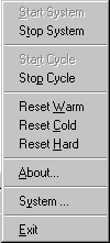
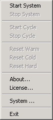
The
commands which are available, depending on the current operational
status, are shown black-colored (enable).
The
following individual operations can be conducted:
-
Start
System loads and activates the driver.
Only then is it possible to work on real time tasks and to
communicate with the programming system. -
Stop
System stops the driver and removes it
from the PC’s memory. -
Start
Cycle / Stop
Cycle start and stop the cyclical
execution of IEC tasks. This operation corresponds with the menu
item «Start»/»Stop» in the online menu of
CoDeSys. -
Next are
the three types of Reset
options which also correspond with the entries in the CoDeSys menu. -
About
shows the splash screen of the RTE which apart from the icon also
includes information on the version and the copyright. -
System
shows a dialogue with system settings. Two settings can be altered
here: If there is a tick behind the option “Start
when booting“ the service will be started automatically by NT on
the next start of the system. This happens completely regardless of
the fact whether a user logs in or not. With the option “Automatic
PLC Start“ the user can decide whether to start the driver
automatically from the service or not. -
Exit
not only stops the driver but also the service after the driver has
been unloaded. The service can be restarted with “Start –
Settings– System Control – Services“ or by the entry in „Start
– Programs“ under CoDeSys. It is possible to start the driver in
“System Control – Devices”, yet this is not very sensible
because it deactivates the driver. The RTE service activates it when
starting. -
License
is only available, if you own a newer version, where the hardlock
(dongle) is replaced by a software license.
Соседние файлы в папке IODriver ToolKit
- #
11.10.20201.36 Кб17CardFunctions.c
- #
11.10.20201.01 Кб17CardFunctions.h
- #
- #
- #
- #
- #
- #
- #
11.10.202018.65 Кб18IOdrvFunctions.c
- #
11.10.20206.88 Кб17IODrvFunctions.h

Д.В.Пастушенков , ООО «Пролог» С.В.Золотарев, ЗАО «РТСофт»
CoDeSys SP RTE: SoftPLC + возможности реального времени в среде Windows Вкратце о CoDeSys
CoDeSys (Controller Development System) немецкой компании Smart Software Solutions GmbH – один из наиболее популярных в Европе комплексов программирования приложений реального времени в стандарте МЭК-61131-3. CoDeSys [1] состоит из двух основных частей: системы программирования и системы исполнения. Система программирования включает в себя редакторы для всех МЭК-языков (ST, SFC, IL, LD, FBD). Имеет развитую систему отладки, средства коллективной разработки проектов, встроенную SCADA-систему и много других полезных разработчику инструментов, то есть все, что нужно для быстрой разработки и внедрения приложений реального времени.
Система программирования содержит встроенные компиляторы для самых различных целевых платформ, таких как Motorola 68xxx, Intel 8086, Intel 8051, Infineon SAB80C16x, Tricore, Power PC, StrongARM, Motorola ColdFire.
Система исполнения – это программа, которая выполняется в целевой платформе и управляет сгенерированным системой программирования кодом. Система исполнения может выполняться на целевой платформе без операционной системы (OC). Функциональные возможности систем исполнения с операционной системой шире, чем у систем исполнения, не использующих ОС. Разработаны системы исполнения под такие операционные системы как WinCE, Windows NT/2000/XP, VxWorks, QNX, RT-OS32 (RTKernel –32), Linux (RTLinux).
Расширения реального времени для Windows NT и средства SoftPLC
В настоящее время на рынке предлагаются несколько коммерческих пакетов, обеспечивающих расширения реального времени для Windows NT/2000/XP [4]. Наиболее известным для российских программистов является пакет RTX фирмы Venturcom (сейчас Ardence, http://www.vci.com)[3]. RTX обеспечивает пользователя средствами и утилитами для построения и выполнения программ реального времени вместе со средствами для измерения и «тонкой» настройки производительности как аппаратных, так и программных средств. RTX глубоко интегрирован в ядро Windows и для обеспечения необходимых функций использует сервис Windows и WIN32 API. Некоторые фирмы-поставщики пакетов класса SoftPLC используют RTX как среду исполнения своих систем. Например, Siemens в своем пакете WinAC или Infoteam в пакете OpenPCS. Достоинством такого подхода является то, что RTX – это универсальное расширение реального времени для Windows NT, применимое для широкого круга приложений. Но с другой стороны, оно само по себе гораздо слабее привязано к специфике задач SoftPLC (например, к интерактивному планированию задач реального времени в терминах объектов SoftPLC-среды). Другим недостатком универсальных расширений реального времени (по сравнению с CoDeSys SP RTE) является более высокая цена как на среду разработки, так и на среду исполнения (стоимость run-time лицензии на RTX+стоимость run-time лицензии на SoftPLC).

CoDeSys SP RTE
CoDeSys SP RTE – включает в себя расширение Windows NT/2000/XP, позволяющее выполнять приложения реального времени, созданные на языках МЭК. Эта возможность обеспечивается подменной стандартного обработчика прерываний от системного таймера. Этот обработчик вызывается периодически через заданный период (по умолчанию, 1мс) времени. Благодаря этому, CoDeSys SP RTE периодически получает управление, причем это никоим образом не нарушает работу приложений Windows NT, а только приостанавливает ее на один или несколько тактов системного таймера. Этот механизм продемонстрирован на рис.1.
Рис. 1. Принцип выполнения CoDeSys SP RTE (длительность владения процессорным временем 50%)
Как видно из рисунка работа CoDeSys SP RTE периодически прерывается. При
этом выполнение задач реального времени приостанавливается на один такт системного таймера, а затем снова возобновляется в соответствии с алгоритмом планирования. На рис.1 показан случай, когда Windows NT и CoDeSys SP RTE делят процессорное время пополам. Однако CoDeSys SP RTE позволяет разработчику задать произвольное соотношение времени владения процессором, т.е. возможна такая ситуация (рис. 2):
Рис. 2. Принцип выполнения CoDeSys SP RTE (длительность владения
процессорным временем 80%) Разработчик выбирает это соотношение самостоятельно, в соответствии с
решаемой им задачей. Для уменьшения времени реакции системы на внешние события период вызова SP
RTE можно уменьшить. Для этого нужно уменьшить период вызова обработчика прерывания от системного таймера. Он может составлять 200, 100, 50 и 25мкс. Эта величина называется базовым квантом времени.
CoDeSys SP RTE имеет структуру, представленную на рис.3.

Рис.3. Структура CoDeSys SP RTE SP RTE состоит из двух основных компонентов: системного сервиса RTService и
драйвера режима ядра RTDrv.sys. RTService выполняется в пользовательском режиме и предназначен для конфигурирования и мониторинга работы системы исполнения, а также асинхронного вызова функций, выполняющихся в пользовательском режиме.
RTDrv.sys выполняется в режиме ядра. Именно этот драйвер вызывает планировщик задач и прикладные задачи реального времени, то есть задачи реального времени также выполняются в режиме ядра, что позволяет им обращаться к любым ресурсам целевой платформы.
Драйверы ввода/вывода (IO Driver) предназначены для управления различными внешними устройствами, например платами ввода/вывода. Они содержат функции инициализации аппаратуры, чтения входов, записи выходов, обработки прерываний и т.д. Шаблон для создания драйвера поставляется вместе с RTE в виде исходных текстов на языке С. Кроме того, вместе с RTE поставляются драйверы для наиболее распространенных устройств.
Gateway-сервер обеспечивает связь системы исполнения и системы программирования. Gateway с одной стороны связан с системой исполнения через разделяемую память, а с другой стороны с системой программирования. В стандартной поставке CoDeSys связь c системой программирования может осуществляться по протоколу TCP/IP или через разделяемую память (в этом случае система исполнения и система программирования должны выполняться на одной целевой платформе). Кроме того, Gateway имеет открытый интерфейс для разработки драйверов связи, благодаря чему можно поддержать различные протоколы связи между системой программирования и системой исполнения, например, СAN или RS-232.
Функциональные возможности CoDeSys SP RTE
Многозадачность Наличие многозадачности является одним из основных требований к системам
реального времени, поэтому начнем именно с нее. Основными элементами проекта в CoDeSys являются программы – объекты,
предназначенные для отображения множества значений входных параметров на множество выходных [2], т.е. это некий программный код, который выполняется для достижения поставленных целей управления в соответствии с текущим состоянием объекта управления.
Проект может состоять из нескольких программ. Правила совместного выполнения программ определяются задачами (tasks), т.е. задача является единицей планирования.

Задача может состоять как из одной, так и нескольких последовательно выполняющихся программ.
Основные этапы выполнения задачи представлены на рис.4
1 Чтения состояния входов
2
Выполнение кода программы 1 Выполнение кода программы 2
.
. Выполнение кода программы N
3 Запись состояния выходов
Рис.4. Основные этапы выполнения задачи Под чтением состояния входов понимается копирование значения физических входов ПЛК (например, значение из АЦП) в специальную область памяти, называемую памятью входов. Программа на протяжении своего выполнения работает именно с этой областью памяти. Работа с выходами обратна работе с входами — прикладная программа пишет значения выходов в память выходов, а в физически выходы ПЛК устанавливаются на этапе 3.
В CoDeSys SP RTE реализована вытесняющая многоприоритетная многозадачность. Каждая задача имеет приоритет, заданный числом от 0 до 31, причем 0 – соответствует самому высокому приоритету. Планировщик задач вызывается в начале каждого кванта времени выделенного SP RTE (см. рис. 1). Если сразу несколько задач претендуют на выполнение, то сначала будет выполнена задача, приоритет которой выше. Выполнение задачи с меньшим приоритетом будет отложено до того момента, когда все задачи с более высоким приоритетом будут выполнены. Если в момент перепланировки процессором владеет задача, приоритет которой ниже, чем у задачи, претендующей на выполнение, то она будет вытеснена. При вытеснении задачи ее контекст (информация о текущем состоянии задачи) сохраняется. Это позволяет планировшику возобновить выполнение задачи с той же инструкции, на которой она была прервана, когда ее приоритет вновь станет самым высоким. Если прикладная задача не успела выполниться в течение базового кванта времени, то ее контекст также сохраниться и будет восстановлен при следующей перепланировке (если конечно не появиться задача с более высоким приоритетом)
В CoDeSys нет механизма диспетчеризации, то есть нельзя создавать несколько задач с одинаковыми приоритетами. Однако в одну задачу можно включать несколько программ.
Отсутствие механизма диспетчеризации приводит к тому, что разработчику приходится более тщательно выбирать приоритеты задач, а это, в свою очередь, повышает надежность создаваемых систем.
Для обмена данными между задачами можно использовать глобальные переменные.
В RTE используются такие механизмы синхронизации задач, как семафоры и события.
Типы и свойства задач SP RTE В SP RTE поддерживаются следующие типы задач:
• Циклические (cyclic) — вызываются через определенные периоды времени. Значение этого периода должно быть кратно базовому кванту времени. Например, если базовый квант времени равен 50мкс, то в

качестве периода вызова циклических задач можно задать 100, 150, 200 мкс и т.д.
• По событию (triggered by event) – задача вызывается, когда значение событийной переменной (event variable) равно истинне.
• По внешнему событию (triggered by event) – аналогичны предыдущему типу, только событие определяется конфигурацией целевой платформы.
• По системному событию – задачи вызываются при возникновении системного события. К системным событиям относятся такие события как возникновение прерывания, исключения, старт/стоп ПЛК. Такие задачи не управляются планировиком и вызываются непосредственно при возникновенни системного события. Так что такая задача в любом случае прерывает выполнение остальных прикладных задач.
• Свободно выполняемые задачи (freewheeling) – этот тип задач аналог задач idle в ОС Windows и QNX. Эта задача имеет самый низкий приоритет и выполняется в последнюю очередь, если процессор не занят выполнением остальных задач.
На каждую задачу можно установить сторожевой таймер. Он определяет максимальное время выполнения задачи. Если значение установленного порога будет превышено, то система будет либо остановлена, либо, если задать обработчик системного события excpt_watchdog, будет вызван обработчик этого события. Требования к устанавливаемым временным порогам такие же, как и к периоду вызова циклических задач.
Для управления задачами используется встроенный в систему программирования CoDeSys конфигуратор задач (рис.5).
Рис.5. Конфигуратор задач CoDeSys Рассмотрим пример планирования задач. Пусть базовый квант времени равен
50мкс, т.е. планировщик задач RTE вызвается с периодом 100мкс. Создадим в конфигураторе задач 5 задач:
• циклическая задача C1 с приоритетом 2 и периодом вызова 200мкс • циклическая задача C2 с приоритетом 3 и периодом вызова 100мкс • выполняемая по событию bEvent задача E с прииритетом 1 • задача-обработчик некоторого системного события S • Свободновыполняемая задача W
Процесс планирования и выполнения этих задач представлен на рис.6.

Рис.6. Пример планирования и выполнения задач
Задача С2 выполняется в каждом интервале времени, выделенного для RTE, так как период вызова этой задачи равен периоду вызова планировщика SP RTE. Задача C1 вызывается в два раза реже. Задача E вызывается в случае, когда переменная bEvent имеет значение TRUE.
Если сразу несколько задач претендуют на выполнение, то они будут выполнены последовательно согласно их приоритету. Задача W выполняется в каждом кванте времени, если остальные задачи закончили свое выполнение до истичения текущего кванта времени.
Если задача не успевает выполниться в течение выделенного кванта времени, как это произошло с задачей C2 в кванте #3), то она вытесняется и ее выполнение возобновляется в следующем кванте. Причем в кванте #4 выполнение задачи C2 будет завершено и возобновлено заново.
Задача S вызывается по системному событию независимо от того, когда оно произошло – во время выполнения RTE или во время выполнения Windows NT.
Доступ к устройствам ввода/вывода
Так как SP RTE используется для решения задач управления, то она должна предоставлять удобные механизмы для доступа к различным устройствам ввода/вывода.
В SP RTE есть несколько таких механизмов. Прежде всего, это интерфейс драйверов ввода/вывода. Каждый драйвер управляет отдельным устройством ввода/вывода. Он содержит функции работы с входами/выходами, которые вызываются на этапах 1 и 3 выполнения программы (см. рис. 4).
Штатный комплект поставки SP RTE уже содержит драйвера для наиболее распространенных устройств. Кроме того, в состав поставки RTE входит пакет разработчика драйверов ввода/вывода, который содержит исходные тексты шаблона драйвера (с комментариями TODO) и документацию. Это позволяет разработчику самому создать драйвер для любого устройства.
Конфигурирование внешних устройств в этом случае производится с помощью конфигуратора ПЛК(PLC Configuration) – объекта, встроенного в систему программирования (см. рис. 7).

Рис.7. Конфигуратор ПЛК Более простым способом для работы с внешними устройствами является
использование внешних библиотек. Функции внешних библиотек используются в проекте как обычные МЭК-функции, но их особенность в том, что реализованы они во внешнем объектном файле, т.е. их можно писать языке С. Эти функции работают в режиме ядра и могут обращаться ко всем ресурсам целевой платформы. Это удобно при реализации низкоуровневых функций доступа к внешним устройствам, например функции чтения данных из регистра периферийного устройства.
Кроме того, в штатную поставку CoDeSys входят системные библиотеки SysLibPorts.lib и SysLibCom.lib. Библиотека SysLibPorts.lib позволяет работать с портами ввода/вывода, что дает возможность управлять устройствами, подключенными к этим портам. SysLibCom.lib используется для работы с последовательными интерфейсами.
Сетевой обмен CoDeSys можно использовать для создания распределенных систем управления благодаря тому, что он поддерживает работу с такимим полевыми сетями, как ProfiBus, DeviceNet и CANOpen. Для работы с этими сетями используется конфигуратор ПЛК (см. рис. 7). Он делает работу с удаленными узлами сети такой же простой, как с обычными входами/выходами. Другим способом сетевого обмена в CoDeSys SP RTE является использование сетевых переменных. Это переменные, доступные всем узлам сети, то есть один узел сети может устанавливать эти переменные, а другие узлы считывать. Механизм сетевых переменных реализован для протоколов CAN и UDP.
Для работы с протоколами UDP и TCP можно пользоваться стандартным механизмом – сокетами. Функции работы с сокетами реализованы в библиотеке SysLibSockets.lib и аналогичны функциям системной библиотеки Windows Winsock.dll.
Взаимодействие с Windows Как уже было сказано выше, одним из главных преимуществ расширений реального времени является использование возможности взаимодействия с обычными приложениями Windows.
Например, необходимо создать приложение реального времени, которое, наряду с остальными, будет использовать устройства, работа с которыми не критична по времени. Большинство таких устройств имеет драйверы только под Windows. В этом случае логично для работы с этими устройствами использовать именно Windows, а в проекте

CoDeSys обеспечить только логику их функционирования. Для этих целей SP RTE имеет специальный механизм асинхронного вызова функции из DLL. Эти функции выполняются под управлением Windows и могут получить доступ ко всем ее ресурсам — файловой системе, драйверам и т.д. Данный механизм реализуется с помощью библиотеки DllCall, содержащей одноименный функциональный блок (см. рис. 8).
Рис.8. Функциональный блок DllCall На вход функционального блока поступает имя функции, которая должна быть
выполнена и эта функция выполняется асинхронно по отношению к задачам CoDeSys в течение времени, выделенного для выполнения Windows NT. Состояние выполнения функции можно определить, вызвав данный функциональный блок еще раз. Если выходной параметр iStatus равен STATUS_PROCESSING, то функция еще находится в процессе выполнения, а если STATUS_READY, то функция была успешно выполнена ОС Windows. Выходной параметр iStatus может принимать еще ряд значений, которые позволяют контролировать процесс выполнения функции, например, если он равен STATUS_EXCEPTION, то функция в процессе своего выполнения вызвала исключение. Функциональный блок DllCall также обеспечивает обмен данными между RTE и Windows NT. Еще одна возможность взаимодействия с Windows NT заключается в том, что из DLL можно асинхронно получить доступ к адресному пространству, в котором выполняются прикладные задачи RTE. В некоторых случаях это очень удобно.
Заметим, что для работы со SCADA-системами, в том числе установленными на целевой платформе, достаточно лишь настроить OPC–сервер, который поставляется вместе с системой программирования бесплатно.
Заключение CoDeSys SP RTE, как интегрированная среда, обеспечивает полную
функциональную поддержку для решения задач пользователя, в том числе интеграцию со SCADA-системами (и даже с установленными на целевой платформе) путем настройки OPC–сервера, который бесплатно поставляется вместе с системой программирования. Другим применением CoDeSys SP RTE является возможность использования его в рамках CoDeSys SoftMotion — функциональным набором средств управления движением, встроенным в среду SoftPLC. Систему программирования CoDeSys и демо-версию CoDeSys SP RTE можно скачать на сайте http://www.3s-software.ru
Литература 1. С.В.Золотарев, И.В.Петров, CoDeSys – интегрированный комплекс МЭК 61131-3
программирования, Приборы и системы управления, N3, 2005. 2. Петров И.В. Программируемые контроллеры. Стандартные языки и приемы
прикладного проектирования /Под ред. проф. В.П. Дьяконова. – М.: СОЛОН-Пресс, 2004. – 256 с.: ил. — (Серия “Библиотека инженера”)
3. П.Кирюхин, RTX – расширение реального времени для Windows NT, http://citforum.cn.ua/operating_systems/rtx/index.shtml
4. Martin Timmerman, Jean-Christophe Monfret, Windows NT as Real-Time OS ? Real-Time Magazine, 97Q2
CoDeSys Control — это часть, которая должна быть встроена в ПЛК. Программируя ПЛК, пользователь должен думать исключительно о сути прикладной задачи. Его не должны волновать организация памяти, процедуры опроса модулей ввода/вывода, способы синхронизации данных, функции сетевого обмена и связи с верхним уровнем, вызовы циклических и событийных задач, организация фиксации выходов при отладке на оборудовании и т. п. Всю черновую работу за него должна выполнить система исполнения.
В общей сложности CoDeSys Control включает более 200 компонентов. Каждая «сборка» под конкретную модель ПЛК будет отличаться. Ее состав определяется возможностями аппаратуры и типом ПЛК. Включение абсолютно всех компонентов, на всякий случай, привело бы к неоправданному росту аппаратных ресурсов и стоимости.
Например, включение функции «горячей» правки кода без остановки ПЛК удваивает требования к ОЗУ.
Некоторые компоненты представлены в нескольких вариантах. Например, компонент «менеджер задач». Самый дешевый ПЛК может иметь единственный аппаратный таймер, «тикающий» каждые 10 мс, и не иметь ОС. Для него подойдет простой планировщик циклических задач без вытеснения. С ним не смогут работать некоторые другие компоненты, например, ЧПУ или стек CANopen, но они и не требуются в ПЛК такого уровня. Для ПЛК с мощным 32 — или 64 — битным процессором и ОС РВ разумно включить наиболее совершенный «менеджер задач» с поддержкой событий, реального времени и нескольких приложений в одном устройстве. С каждым таким приложением можно работать как с независимым ПЛК: загружать, запускать, останавливать и отлаживать программы, не влияя на работу других приложений.
CoDeSys Control может функционировать под управлением любой ОС или даже без нее. Наиболее часто используют ОС VxWorks, Windows CE и Linux. Имеются адаптации под RT — OS32 (RTKernel), QNX, Nucleus, pSOS, OS9, TenAsys INtime. Изготовитель оборудования может самостоятельно адаптировать CoDeSys Control под другую ОС.
-

CODESYS Control Win SL
2302000003CODESYS Control Win SL is an IEC 61131-3 SoftPLC for PC-based industrial controllers (PLCs) under Windows with soft real-time properties.
Learn More
-
CODESYS Control Win MC SL
2302000030
€110.00
CODESYS Control Win MC SL is an extension of CODESYS Control Win SL – an IEC 61131-3-compliant SoftPLC for PC-based industrial controllers running on Windows with soft real-time properties.
Learn More
-
Free!
-
-
CODESYS Control RTE SL
2302000000CODESYS Control RTE SL is a real-time software PLC for PC-based industrial controllers under Windows — programmable with the IEC 61131-3 development System CODESYS.
Learn More
-
CODESYS Control RTE MC SL
2302000043
€110.00
A multicore extension for CODESYS Control RTE SL — an IEC 61131-3 compliant real-time SoftPLC for PC-based industrial controllers under Windows.
Learn More