Welcome to this tutorial! This is a simple step by step guide of configuring VLAN and interVLAN routing on a Cisco switch. But just before get into configurations , let’s have a brief overview of what’s a VLAN.
What is a VLAN?
A Virtual LAN (VLAN) is simply a logical LAN, just as its name suggests. VLANs have similar characteristics with those of physical LANs, only that with VLANs, you can logically group hosts even if they are physically located on separate LAN segments.
We treat each VLAN as a separate subnet or broadcast domain. For this reason, to move packets from one VLAN to another, we have to use a router or a layer 3 switch.
VLANs are configured on switches by placing some interfaces into one broadcast domain and some interfaces into another. For this tutorial, we’ll configure 2 VLANs on a switch. We’ll then proceed and configure a router to enable communication between the two VLANs.
So then,
- In Cisco Packet Tracer, create the network topology as shown below:

2. Create 2 VLANs on the switch: VLAN 10 and VLAN 20. You can give them custom names.
Switch#config terminal
Switch(config)#vlan 10
Switch(config-vlan)#name SALES
Switch(config-vlan)#vlan 20
Switch(config-vlan)#name IT
3. Assign switch ports to the VLANs. Remember each VLAN is viewed as separate broadcast domain.
And just before you configure, have in mind that switch ports could be either access or trunk.
- An access port is assigned to a single VLAN . These ports are configured for switch ports that connect to devices with a normal network card, for example a PC in a network.
- A trunk port on the other hand is a port that can be connected to another switch or router. This port can carry traffic of multiple VLANs.
So in our case, we’ll configure switch interfaces fa 0/1 through fa 0/4 as access ports to connect to our PCs. Here, interfaces fa 0/1 and fa 0/2 are assigned to VLAN 10 while interfaces fa 0/3 and fa 0/4 are assigned to VLAN 20.
Switch Interface fa0/5 will be configured as trunk port, as it will be used to carry traffic between the two VLANs via the router.
Switch>enable
Switch#config terminal

Switch(config)#int fa0/1
Switch(config-if)#switchport mode access
Switch(config-if)#switchport access vlan 10

Switch(config-if)#int fa0/2
Switch(config-if)#switchport mode access
Switch(config-if)#switchport access vlan 10

Switch(config-if)#int fa0/3
Switch(config-if)#switchport mode access
Switch(config-if)#switchport access vlan 20

Switch(config-if)#int fa0/4
Switch(config-if)#switchport mode access
Switch(config-if)#switchport access vlan 20
Worth noting: We could have configured all the above interfaces as access ports using interface range command as shown below:
Switch(config-if)#int range fa0/1-4
Switch(config-if-range)#switchport mode access
In the above commands, we have specified an interface range and then proceeded to configure all the ports specified as access ports.
Interface fa0/5 is configured as trunk and will be used to for inter-VLAN communication.
Switch(config)#int fa 0/5
Switch(config-if)#switchport mode trunk
The next thing is to:
4 . Assign static IP addresses to the four PCs which are located in the separate VLANs. PC1 and PC2 fall in VLAN 10 while PC3 and PC4 fall in VLAN 20.
PC1 IP address 192.168.1.10 Subnet mask 255.255.255.0 Default gateway 192.168.1.1
PC2: IP address 192.168.1.20 Subnet mask 255.255.255.0 Default gateway 192.168.1.1
PC3: IP address 192.168.2.10 Subnet mask 255.255.255.0 Default gateway 192.168.2.1
PC4: IP address 192.168.2.20 Subnet mask 255.255.255.0 Default gateway 192.168.2.1
And now it’s very clear that we treat a VLAN just like a physical LAN when assigning IP addresses.
At this point let’s try to test connectivity within VLANs and between VLANs
To test communication between hosts in the same VLAN:
Ping PC2 from PC1 both in VLAN 10. Ping test should be successful.
To test connectivity between hosts in different VLANs:
Ping PC3 in VLAN 20 from PC1 in VLAN 10. Ping here will definitely fail. Why? Because inter-VLAN routing is not yet enabled. Hope you can see how we’ve used VLANs to place the hosts into two logical networks which can be viewed as separate broadcast domains.
Now, in order to allow the hosts in the two VLANs to communicate, we need to do something extra. And you can guess what. We’ll configure the router to permit inter-VLAN communication. Let’s do that right away.
5. Configure inter-VLAN routing on the router
We’ll configure the router so that it will enable communication between the two vlans via a single physical interface. How is this made possible? We’ll divide the single physical interface on the router into logical interfaces (sub interfaces). Each sub-interface will then serve as a default gateway for each of the VLANs. This scenario is called router on a stick (R.O.A.S) and will allow the VLANs to communicate through the single physical interface.
Wort noting: We can’t assign an IP address to the router’s physical interface that we have subdivided into logical sub-interfaces. We’ll instead assign IP addresses to the sub interfaces.
So let’s do router configurations:
Router>enable
Router#config terminal

Router(config)#int fa0/0
Router(config-if)#no shutdown

Router(config-if)#int fa0/0.10
Router(config-subif)#encapsulation dot1q 10
Router(config-subif)#ip add 192.168.1.1 255.255.255.0
Router(config-subif)#

Router(config-subif)#int fa0/0.20
Router(config-subif)#encapsulation dot1q 20
Router(config-subif)#ip add 192.168.2.1 255.255.255.0
As you can notice from above, the routers physical interface fa0/0 was subdivided into two sub-interfaces( fa0/0.10 and fa0/0.20) , which are then configured as trunk interfaces and given IP addresses.
Finally,
6. Test inter-VLAN connectivity.
Here we’ll test connectivity between computers in different VLANs . Don’t forget that its the router that enables inter-VLAN routing.
Ping PC3 in VLAN 20 from PC1 in VLAN 10. If everything is well configured, then ping should work perfectly.
And that’s all!
Hope this article was useful to you. Comment to help improve it.
All the best.
See also:
- Configuring Switch Port Security in Packet Tracer
В статьях этого блога мы уже обсуждали с вами принципы создания vlan на коммутаторах фирмы Cisco, но, к сожалению, у нас пока никак не доходили руки разобрать вопросы маршрутизации между различными vlan-ами. Сегодня мы исправим эту оплошность и разберем один из методов такой маршрутизации, называемый «маршрутизатор на привязи».
Как бы это не было прискорбно, но осуществить маршрутизацию между vlan не получится только с помощью средств самого коммутатора (в данном случае имеется ввиду коммутатор уровня 2), для этих целей придется использовать дополнительное устройство – уже знакомый нам маршрутизатор. Как мы помним, маршрутизатор может осуществлять маршрутизацию пакетов между сетями, подключенными к его различным интерфейсам. Но кроме этого маршрутизатор так же умеет выполнять маршрутизацию между vlan-ами, подведенными всего лишь к одному его физическому интерфейсу. Принцип данной маршрутизации проиллюстрирован на рисунке:
 |
| «Маршрутизатор на привязи» |
Данный способ маршрутизации обычно называют «Маршрутизатор на привязи», так как маршрутизатор получается как бы привязанным одним линком к коммутатору.
Давайте попробуем посмотреть как необходимо сконфигурировать коммутатор и маршрутизатор фирмы Cisco для реализации данной схемы. Для этого в Packet Tracer соберем следующую схемку (порты подключения всех устройств соответствуют первому рисунку):
 |
| Реализация маршрутизатора на привязи в Packet Tracer |
Компьютеру PС0 зададим IP адрес 192.168.1.2, маску 255.255.255.0 и основной шлюз 192.168.1.1. Компьютеру PС1 зададим IP адрес 10.10.10.2, маску 255.0.0.0 и основной шлюз 10.10.10.1.
Далее мы сконфигурируем наш коммутатор для работы с портами доступа vlan:
Switch(config)#vlan 2
Switch(config-vlan)#name vlan_number_2
Switch(config-vlan)#exit
Switch(config)#interface fastEthernet 0/1
Switch(config-if)#switchport mode access
Switch(config-if)#switchport access vlan 2
Switch(config-if)#exit
Switch(config)#vlan 3
Switch(config-vlan)#name vlan_number_3
Switch(config-vlan)#exit
Switch(config)#interface fastEthernet 0/2
Switch(config-if)#switchport mode access
Switch(config-if)#switchport access vlan 3
Switch(config-if)#exit
Первыми семью командами вы создаете на коммутаторе vlan 2 и делаете порт коммутатора fastEthernet 0/1 портом доступа данного vlan. Следующими командами вы делаете тоже самое но уже для vlan 3 и порта fastEthernet 0/2.
Если в данный момент вы попробуете пропинговать с компьютера из vlan 2 компьютер из vlan 3, то вы не получите ничего хорошего, ваши пинги не пройдут. Так как данные компьютеры будут находиться в разных vlan, а маршрутизацию между данными vlan еще не настроена.
Продолжим производить настройки. Подведем наши vlan 2 и vlan 3 через транковый порт коммутатора к интерфейсу маршрутизатора:
Switch(config)#interface fastEthernet 0/24
Switch(config-if)#switchport mode trunk
Switch(config-if)#switchport trunk allowed vlan 2-3
На маршрутизаторе, для начала включим интерфейс, к которому подключен коммутатор:
Router(config)#interface fastEthernet 0/1
Router(config-if)#no shutdown
Подождем пока интерфейс маршрутизатора поднимется и снова попробуем пропинговать с компьютера из vlan 2 компьютер из vlan 3. Результат будет все тот же. Пинги не будут проходить, так как маршрутизатор мы еще не настраивали для работы с vlan, приходящими на его порт.
Для того чтобы все же настроить маршрутизацию между данными vlan, создадим на интерфейсе маршрутизатора субинтерфейсы предназначенные для наших vlan (по одному субинтерфейсу под каждый vlan) и присвоим им IP адреса, которые мы указали на компьютерах в качестве основных шлюзов:
Router(config)#interface fastEthernet 0/1.2
Router(config-subif)#encapsulation dot1Q 2
Router(config-subif)#ip address 192.168.1.1 255.255.255.0
Router(config)#interface fastEthernet 0/1.3
Router(config-subif)#encapsulation dot1Q 3
Router(config-subif)#ip address 10.10.10.1 255.0.0.0
Router(config-subif)#exit
Если все сделано верно, то при попытке пропинговать компьютер из vlan 3 с компьютера из vlan 2 он должен быть доступен.
Теперь маршрутизация между данными vlan работает и на этом мы закончим сегодняшнюю статью
The VLAN (Virtual LAN) structure is used to divide the physical network topology into logical network segments. When VLANs are configured, the physical network environment provides better performance and better network management.

How to Create and Configure VLANs on Cisco Switch with Packet Tracer
In a physical network environment, you can allocate users in a specific location to logical areas with VLANs. For example, if a 3-floor company has a finance department on each floor, you can configure a VLAN so that you can communicate these departments between floors.
In the actual scenario, users do not take notice of this change when you do this. By simply grouping the existing network logically, you get more network performance, and you can also restrict data traffic between VLAN groups.
You can now follow the steps below to create and configure VLANs on Switches using the simulator software.
Step 1
First, add a Router, Switch, and six PCs to the Packet Tracer workspace to create a network topology as shown in the image below.

Step 2
After configuring the Cisco Router’s interface and the TCP/IP settings of the computers, click Switch and click the CLI tab in the window that opens. To change to Privileged mode, execute enable.

Step 3
After making the basic settings, create 3 different VLAN groups according to the topology you have created on the Switch. Use the following commands to create a VLAN by topology.
Switch# conf t
Switch(config)# hostname SWITCH
SWITCH(config)# vlan 10
SWITCH(config-vlan)# name VLAN10
SWITCH(config-vlan)# exit
SWITCH(config)# vlan 20
SWITCH(config-vlan)# name VLAN20
SWITCH(config-vlan)# exit
SWITCH(config)# vlan 30
SWITCH(config-vlan)# name VLAN30
SWITCH(config-vlan)# exit

Step 4
After creating VLANs for departments, you need to make clients connected to the Switch interface to VLANs.
Switch from privileged configuration mode on Cisco Switch to global configuration mode.
To assign clients in the red zone to VLAN10, perform the following commands in order.
SWITCH# conf t
SWITCH(config)# interface fastethernet 0/1
SWITCH(config-if)# switchport mode access
SWITCH(config-if)# switchport access vlan 10
SWITCH(config-if)# exit
SWITCH(config)# interface fastethernet 0/2
SWITCH(config-if)# switchport mode access
SWITCH(config-if)# switchport access vlan 10
SWITCH(config-if)# exit
SWITCH(config)# end

Step 5
To assign clients in the blue zone to VLAN20, perform the following commands in order.
SWITCH# conf t
SWITCH(config)# interface fastethernet 0/3
SWITCH(config-if)# switchport mode access
SWITCH(config-if)# switchport access vlan 20
SWITCH(config-if)# exit
SWITCH(config)# interface fastethernet 0/4
SWITCH(config-if)# switchport mode access
SWITCH(config-if)# switchport access vlan 20
SWITCH(config-if)# exit
SWITCH(config)# end

Step 6
To assign clients in the green zone to the VLAN20, perform the following commands in order.
SWITCH# conf t
SWITCH(config)# interface fastethernet 0/5
SWITCH(config-if)# switchport mode access
SWITCH(config-if)# switchport access vlan 30
SWITCH(config-if)# exit
SWITCH(config)# interface fastethernet 0/6
SWITCH(config-if)# switchport mode access
SWITCH(config-if)# switchport access vlan 30
SWITCH(config-if)# exit
SWITCH(config)# end

Step 7
After adding the Switchport to the VLANs, check the interfaces you have created and made on the Switch with the show vlan command.

Step 8
Since the network ports of PC0 and PC1 are connected to the VLAN10, you will see that there is a connection when you ping between these computers.

Step 9
When you ping between computers with other VLANs, you will see that the operation failed.
A ping test from PC0 to PC2 which is a member of VLAN20;

Step 10
When you ping PC4 from PC0 to VLAN30 member, ping will fail. The reason ping failed is that no routing has been made between the VLANs.
NOTE: When you configure VLANs on the Layer 2 switch, if there is a Router in the environment, you need to configure the Inter-VLAN.

Assigning a Management IP Address to VLANs
By granting a management IP address to VLANs, you can control your devices from the local or remote network.
The ip address command is used in the configuration mode of the port to assign an IP address to the interface of a router. In the Switch, this operation is performed in the settings of the VLAN you will assign IP.
A management IP can be assigned for each VLAN created.
To add management addresses for VLAN10, VLAN20, and VLAN30, addressing the network topology, follow these steps:
Step 1
In CLI, execute the configure terminal command and then the interface command (name of the vlan) to configure the corresponding VLAN.
SWITCH#conf t
Enter configuration commands, one per line. End with CNTL/Z.
SWITCH(config)#interface vlan 10
SWITCH(config-if)#
%LINK-5-CHANGED: Interface Vlan10, changed state to up
%LINEPROTO-5-UPDOWN: Line protocol on Interface Vlan10, changed state to up
SWITCH(config-if)#ip address 192.168.10.100 255.255.255.0
SWITCH(config-if)#no shutdown
SWITCH(config-if)#exit
SWITCH(config)#
SWITCH(config)#interface vlan 20
SWITCH(config-if)#
%LINK-5-CHANGED: Interface Vlan20, changed state to up
%LINEPROTO-5-UPDOWN: Line protocol on Interface Vlan20, changed state to up
SWITCH(config-if)#ip address 192.168.20.100 255.255.255.0
SWITCH(config-if)#no shutdown
SWITCH(config-if)#exit
SWITCH(config)#
SWITCH(config)#interface vlan 30
SWITCH(config-if)#
%LINK-5-CHANGED: Interface Vlan30, changed state to up
%LINEPROTO-5-UPDOWN: Line protocol on Interface Vlan30, changed state to up
SWITCH(config-if)#ip address 192.168.30.100 255.255.255.0
SWITCH(config-if)#no shutdown
SWITCH(config-if)#end
SWITCH#

Step 2
You can examine the IP addresses and port states of the interfaces with the show ip interface brief command in the switch.

Step 3
Pinging from PC0 to VLAN 10 management IP address (192.168.10.100) will be successful as follows.

Step 4
When you ping the VLAN 20 and VLAN 30 IP addresses (192.168.20.100 and 192.168.30.100) from PC0, the operation will fail.

Step 5
Finally, when you ping the management address from PC2, which is a member of VLAN20, the ping will succeed because clients that are members of the same VLAN can communicate.
If you ping the management address of the other VLAN, the operation will still fail.

Show Commands
SWITCH#show vlan

VLAN Name Status Ports
---- -------------------------------- --------- -------------------------------
1 default active Fa0/7, Fa0/8, Fa0/9, Fa0/10
Fa0/11, Fa0/12, Fa0/13, Fa0/14
Fa0/15, Fa0/16, Fa0/17, Fa0/18
Fa0/19, Fa0/20, Fa0/21, Fa0/22
Fa0/23, Fa0/24, Gig0/1, Gig0/2
10 VLAN10 active Fa0/1, Fa0/2
20 VLAN20 active Fa0/3, Fa0/4
30 VLAN30 active Fa0/5, Fa0/6
1002 fddi-default active
1003 token-ring-default active
1004 fddinet-default active
1005 trnet-default active

VLAN Type SAID MTU Parent RingNo BridgeNo Stp BrdgMode Trans1 Trans2
---- ----- ---------- ----- ------ ------ -------- ---- -------- ------ ------
1 enet 100001 1500 - - - - - 0 0
10 enet 100010 1500 - - - - - 0 0
20 enet 100020 1500 - - - - - 0 0
30 enet 100030 1500 - - - - - 0 0
1002 fddi 101002 1500 - - - - - 0 0
1003 tr 101003 1500 - - - - - 0 0
1004 fdnet 101004 1500 - - - ieee - 0 0
1005 trnet 101005 1500 - - - ibm - 0 0

Remote SPAN VLANs
------------------------------------------------------------------------------

Primary Secondary Type Ports
------- --------- ----------------- ------------------------------------------
SWITCH#
SWITCH#show vlan brief

VLAN Name Status Ports
---- -------------------------------- --------- -------------------------------
1 default active Fa0/7, Fa0/8, Fa0/9, Fa0/10
Fa0/11, Fa0/12, Fa0/13, Fa0/14
Fa0/15, Fa0/16, Fa0/17, Fa0/18
Fa0/19, Fa0/20, Fa0/21, Fa0/22
Fa0/23, Fa0/24, Gig0/1, Gig0/2
10 VLAN10 active Fa0/1, Fa0/2
20 VLAN20 active Fa0/3, Fa0/4
30 VLAN30 active Fa0/5, Fa0/6
1002 fddi-default active
1003 token-ring-default active
1004 fddinet-default active
1005 trnet-default active
SWITCH#
SWITCH#show running-config
Building configuration...

Current configuration : 1351 bytes
!
version 12.2
no service timestamps log datetime msec
no service timestamps debug datetime msec
no service password-encryption
!
hostname SWITCH
!
!
spanning-tree mode pvst
!
interface FastEthernet0/1
switchport access vlan 10
switchport mode access
!
interface FastEthernet0/2
switchport access vlan 10
switchport mode access
!
interface FastEthernet0/3
switchport access vlan 20
switchport mode access
!
interface FastEthernet0/4
switchport access vlan 20
switchport mode access
!
interface FastEthernet0/5
switchport access vlan 30
switchport mode access
!
interface FastEthernet0/6
switchport access vlan 30
switchport mode access
!
interface FastEthernet0/7
!
interface FastEthernet0/8
!
interface FastEthernet0/9
!
interface FastEthernet0/10
!
interface FastEthernet0/11
!
interface FastEthernet0/12
!
interface FastEthernet0/13
!
interface FastEthernet0/14
!
interface FastEthernet0/15
!
interface FastEthernet0/16
!
interface FastEthernet0/17
!
interface FastEthernet0/18
!
interface FastEthernet0/19
!
interface FastEthernet0/20
!
interface FastEthernet0/21
!
interface FastEthernet0/22
!
interface FastEthernet0/23
!
interface FastEthernet0/24
!
interface GigabitEthernet0/1
!
interface GigabitEthernet0/2
!
interface Vlan1
no ip address
shutdown
!
line con 0
!
line vty 0 4
login
line vty 5 15
login
!
end
SWITCH#
SWITCH#show ip interface brief
Interface IP-Address OK? Method Status Protocol
FastEthernet0/1 unassigned YES manual up up
FastEthernet0/2 unassigned YES manual up up
FastEthernet0/3 unassigned YES manual up up
FastEthernet0/4 unassigned YES manual up up
FastEthernet0/5 unassigned YES manual up up
FastEthernet0/6 unassigned YES manual up up
FastEthernet0/7 unassigned YES manual down down
FastEthernet0/8 unassigned YES manual down down
FastEthernet0/9 unassigned YES manual down down
FastEthernet0/10 unassigned YES manual down down
FastEthernet0/11 unassigned YES manual down down
FastEthernet0/12 unassigned YES manual down down
FastEthernet0/13 unassigned YES manual down down
FastEthernet0/14 unassigned YES manual down down
FastEthernet0/15 unassigned YES manual down down
FastEthernet0/16 unassigned YES manual down down
FastEthernet0/17 unassigned YES manual down down
FastEthernet0/18 unassigned YES manual down down
FastEthernet0/19 unassigned YES manual down down
FastEthernet0/20 unassigned YES manual down down
FastEthernet0/21 unassigned YES manual down down
FastEthernet0/22 unassigned YES manual down down
FastEthernet0/23 unassigned YES manual down down
FastEthernet0/24 unassigned YES manual down down
GigabitEthernet0/1 unassigned YES manual up up
GigabitEthernet0/2 unassigned YES manual down down
Vlan1 unassigned YES manual administratively down down
Vlan10 192.168.10.100 YES manual up up
Vlan20 192.168.20.100 YES manual up up
Vlan30 192.168.30.100 YES manual up up
Video
You can watch the video below to create virtual LANs on Packet Tracer and also subscribe to our YouTube channel to support us!
Final Word
In this article, we have examined how to create VLANs in a Cisco Switch with the simulator program, and assign an IP address to the VLAN. If you want to enable data communication between VLANs, you must activate the Inter-VLAN. Thanks for following us!
Related Articles
♦ Create a Network
♦ VLAN Routing
♦ SSH
♦ Telnet
♦ DHCP Relay Agent
⇒ CISCO ⇐
Voice(Asterisk\Cisco)
Microsoft
Powershell
Python
SQL\T-SQL
FreeBSD and Nix
1С
Общая
WEB Разработка
ORACLE SQL \ JAVA
Мото
Стрельба, пневматика, оружие
Саморазвитие и психология
Продолжаем серию статей по cisco.
Ссылка на первую http://snakeproject.ru/rubric/article.php?art=packet_tracer_1
В данной статье мы построим более сложную сеть с dhcp, vlan`ами, и статической маршрутизацией.
dhcp нужен как сервер раздачи ip адресов по сети.
vlan разделяют сеть на логические сегменты(повышают безопастность, разделяют сегменты доступа по сети)
статическая маршрутизация определяется в виде записей маршрутов для прохождения пакетов по сети.
Скачайте проект для packet tracer файл
Открываем и смотрим настройки:
Видео выложу на своем канале YouTube
Комментарии пользователей
Анонимам нельзя оставоять комментарии, зарегистрируйтесь!
Код обмена баннерами


![]()
![]()
")
© Snakeproject.ru создан в 2013 году.
При копировании материала с сайта — оставьте ссылку.
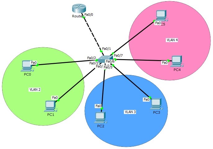
Table of Contents
Router on Stick Configuration on Packet Tracer
VLANs are the virtual LANS that provide divide your big network, into smaller pieces. Many companies use to divide their networks into different departments. We have discussed the basic logic of VLANs in the previous articles.As you know each VLAN is a seperate VLAN. Each of them is a single network. So at the beginning, there is no communication between VLAN. To enable the communication of these different sub networks, we need Inter VLAN Routing. In other words, this topology called “Router on Stick” topology. Inter VLAN Routing topology or Router on Stick topology is a very common topology for CCNA exams. We will learn Routing on Stick Topology and Router on Stick Config on this lesson.
You can DOWNLOAD the Packet Tracer example with .pkt format At the End of This Lesson.
You can also DOWNLOAD all the Packet Tracer examples with .pkt format in Packet Tracer Labs section.
You can download “Cisco Packet Tracer” in Tools section.
In this article, we will use the below Router on Stick topology and we will configure Inter VLAN Routing on Packet Tracer.
 Router on Stick Topology
Router on Stick (Inter VLAN Routing) topology basically consist of one switch and a router. Here, the switch is the place that our VLANs exist and the router is the device that route the traffic.
Router on Stick Configuration Steps
For Router on Stick topology (Inter VLAN Routing) configuration, we will create router virtual interfaces under the router interfaces. Then, we will assign each of this virtual interface to a specific VLAN. We will also create our VLANs and configure the PCs on that VLAN. For Router on Stick topology (Inter VLAN Routing), we will use one switch, one router and six PCs in Packet Tracer. And we will have 3 VLANs.
Let’s start to configure our Router on Stick topology (Inter VLAN Routing).
IP Configurations For Inter VLAN Routing
We will use 10.0.0.0/24, 20.0.0.0/24 and 30.0.0.0/24 blocks for our Packet Tracer Router on Stick topology example. The first block will be for VLAN 2, the second will be for VLAN 3 and the last one will be for VLAN 4.
Firstly, we ll configure the IP addresses of the PCs on Packet Tracer like below.
PC0 : 10.0.0.2 255.255.255.0
GW : 10.0.0.1
PC1 : 10.0.0.3 255.255.255.0
GW : 10.0.0.1
PC2 : 20.0.0.2 255.255.255.0
GW : 20.0.0.1
PC3 : 20.0.0.3 255.255.255.0
GW : 20.0.0.1
PC4 : 30.0.0.2 255.255.255.0
GW : 30.0.0.1
PC5 : 30.0.0.3 255.255.255.0
GW : 30.0.0.1
Here, the gateway addresses of the PCs will be the IP address of router virtual interfaces. Each router virtual interface will have an IP addresses as gateway of one of the VLANs.
Creating VLANs
Now, let’s configure our VLANs and assign the interfaces to these VLANs. Firstly we will create VLAN 2,3 and 4. Then, we will enter the interface range and configure the interface range as access interface. Lastly, we will assign the interface to a specific VLAN with “switchport access vlan” command.
Switch (config) # vlan 2
Switch (config-vlan) # vlan 3
Switch (config-vlan) # vlan 4
Switch (config-vlan) # exit
Switch (config) # interface range fastEthernet 0/2-3
Switch (config-if-range) # switchport mode access
Switch (config-if-range) # switchport access vlan 2
Switch (config-if-range) # exit
Switch (config) # interface range fastEthernet 0/4-5
Switch (config-if-range) # switchport mode access
Switch (config-if-range) # switchport access vlan 3
Switch (config-if-range) # exit
Switch (config) # interface range fastEthernet 0/6-7
Switch (config-if-range) # switchport mode access
Switch (config-if-range) # switchport access vlan 4
Switch (config-if-range) # exit
Our VLAN configurations are OK on the switch now. Let’s verify the VLANs.
You can also DOWNLOAD all the Packet Tracer examples with .pkt format in Packet Tracer Labs section.
Switch# show vlan
VLAN Name Status Ports
—- ——————————– ——— ——————————-
1 default active Fa0/8, Fa0/9, Fa0/10, Fa0/11
Fa0/12, Fa0/13, Fa0/14, Fa0/15
Fa0/16, Fa0/17, Fa0/18, Fa0/19
Fa0/20, Fa0/21, Fa0/22, Fa0/23
Fa0/24, Gig0/1, Gig0/2
2 VLAN0002 active Fa0/2, Fa0/3
3 VLAN0003 active Fa0/4, Fa0/5
4 VLAN0004 active Fa0/6, Fa0/7
1002 fddi-default act/unsup
1003 token-ring-default act/unsup
1004 fddinet-default act/unsup
1005 trnet-default act/unsupAN Type SAID MTU Parent RingNo BridgeNo Stp BrdgMode Trans1 Trans2
—- —– ———- —– —— —— ——– —- ——– —— ——
1 enet 100001 1500 – – – – – 0 0
2 enet 100002 1500 – – – – – 0 0
3 enet 100003 1500 – – – – – 0 0
4 enet 100004 1500 – – – – – 0 0
As you can see, for our Router on Stick topology, Interface Fa0/2 and Fa0/3 are the member of VLAN 2, Interface Fa0/4 and Fa0/5 are the member of VLAN 3, Interface Fa0/6 and Fa0/7 are the member of VLAN 4. Interface Fa0/1 is not on the VLAN table. Because it is our Trunking port.
Trunk Interface Configuration
It is time to configure the switch’s router face interface, interface 0/1. We will connect switch to the router, with this interface. This interface will be a trunk port. In our Router on Stick topology, Trunk interface will pass all our VLANs that we allowed.
Switch (config) # interface fastEthernet 0/1
Switch (config-if) # switchport mode trunk
Switch (config-if) # switchport trunk allowed vlan 2,3,4
Switch (config-if) # exit
Router on Stick Configuration
Our switch configuration is ok, on Packet Tracer. We can configure the router, Router on Stick now. On Router on Stick, we will configure Fa0/0 interface and the router virtual interfaces under this interface for Inter VLAN Routing.
Router (config) # interface fastEthernet 0/0
Router (config-if) # no shutdown
Router (config-if) # exit
