Basic IP Routing
This module describes how to configure basic IP routing. The Internet Protocol (IP) is a network layer (Layer 3) protocol
that contains addressing information and some control information that enables packets to be routed. IP is documented in RFC
791 and is the primary network layer protocol in the Internet protocol suite.
Finding Feature Information
Your software release may not support all the features documented in this module. For the latest caveats and feature information,
see Bug Search Tool and the release notes for your platform and software release. To find information about the features documented in this module,
and to see a list of the releases in which each feature is supported, see the feature information table.
Use Cisco Feature Navigator to find information about platform support and Cisco software image support. To access Cisco Feature
Navigator, go to www.cisco.com/go/cfn. An account on Cisco.com is not required.
Information About Basic IP Routing
Variable-Length Subnet Masks
Enhanced Interior Gateway Routing Protocol (EIGRP), Intermediate System-to-Intermediate System (IS-IS), Open Shortest Path
First (OSPF), Routing Information Protocol (RIP) Version 2, and static routes support variable-length subnet masks (VLSMs).
With VLSMs, you can use different masks for the same network number on different interfaces, which allows you to conserve
IP addresses and more efficiently use available address space. However, using VLSMs also presents address assignment challenges
for the network administrator and ongoing administrative challenges.
Refer to RFC 1219 for detailed information about VLSMs and how to correctly assign addresses.

Note |
Consider your decision to use VLSMs carefully. You can easily make mistakes in address assignments and you will generally |
The best way to implement VLSMs is to keep your existing addressing plan in place and gradually migrate some networks to
VLSMs to recover address space.
Static Routes
Static routes are user-defined routes that cause packets moving between a source and a destination to take a specified path.
Static routes can be important if the device cannot build a route to a particular destination. They are also useful for specifying
a gateway of last resort to which all unroutable packets will be sent.
To configure a static route, use the
ip route
prefix mask {ip-address |
interface-type interface-number [ip-address]} [distance] [name] [permanent |
track
number] [tag
tag] global configuration command.
Static routes remains in the device configuration until you remove them (using the
no ip route global configuration command). However, you can override static routes with dynamic routing information through prudent assignment
of administrative distance values. An administrative distance is a rating of the trustworthiness of a routing information
source, such as an individual router or a group of routers. Numerically, an administrative distance is an integer from 0 to
255. In general, the higher the value, the lower the trust rating. An administrative distance of 255 means the routing information
source cannot be trusted at all and should be ignored.
Each dynamic routing protocol has a default administrative distance, as listed in the table below. If you want a static route
to be overridden by information from a dynamic routing protocol, simply ensure that the administrative distance of the static
route is higher than that of the dynamic protocol.
|
Route Source |
Default Distance |
|---|---|
|
Connected interface |
0 |
|
Static route |
1 |
|
Enhanced Interior Gateway Routing Protocol (EIGRP) summary route |
5 |
|
External Border Gateway Protocol (BGP) |
20 |
|
Internal EIGRP |
90 |
|
Interior Gateway Routing Protocol (IGRP) |
100 |
|
Open Shortest Path First (OSPF) |
110 |
|
intermediate System to Intermediate System (IS-IS) |
115 |
|
Routing Information Protocol (RIP) |
120 |
|
Exterior Gateway Routing Protocol (EGP) |
140 |
|
On Demand Routing (ODR) |
160 |
|
External EIGRP |
170 |
|
Internal BGP |
200 |
|
Unknown |
255 |
Static routes that point to an interface are advertised via RIP, EIGRP, and other dynamic routing protocols, regardless of
whether
redistribute static router configuration commands are specified for those routing protocols. These static routes are advertised because static
routes that point to an interface are considered in the routing table to be connected and hence lose their static nature.
However, if you define a static route to an interface that is not one of the networks defined in a
network command, no dynamic routing protocols will advertise the route unless a
redistribute static command is specified for these protocols.
When an interface goes down, all static routes through that interface are removed from the IP routing table. Also, when the
software can no longer find a valid next hop for the address specified as the address of the forwarding device in a static
route, the static route is removed from the IP routing table.
Default Routes
Default routes, also known as gateways of last resort, are used to route packets that are addressed to networks not explicitly
listed in the routing table. A device might not be able to determine routes to all networks. To provide complete routing capability,
network administrators use some devices as smart devices and give the remaining devices default routes to the smart device.
(Smart devices have routing table information for the entire internetwork.) Default routes can be either passed along dynamically
or configured manually into individual devices.
Most dynamic interior routing protocols include a mechanism for causing a smart device to generate dynamic default information,
which is then passed along to other devices.
-
ip default-gateway
-
ip default-network
-
ip route 0.0.0.0 0.0.0.0
You can use the
ip default-gateway global configuration command to define a default gateway when IP routing is disabled on a device. For instance, if a device
is a host, you can use this command to define a default gateway for the device. You can also use this command to transfer
a Cisco software image to a device when the device is in boot mode. In boot mode, IP routing is not enabled on the device.
Unlike the
ip default-gateway command, the
ip default-network command can be used when IP routing is enabled on a device. When you specify a network by using the
ip default-network command, the device considers routes to that network for installation as the gateway of last resort on the device.
Gateways of last resort configured by using the
ip default-network command are propagated differently depending on which routing protocol is propagating the default route. For Interior Gateway
Routing Protocol (IGRP) and Enhanced Interior Gateway Routing Protocol (EIGRP) to propagate the default route, the network
specified by the
ip default-network command must be known to IGRP or EIGRP. The network must be an IGRP- or EIGRP-derived network in the routing table, or the
static route used to generate the route to the network must be redistributed into IGRP or EIGRP or advertised into these protocols
by using the
network command. The Routing Information Protocol (RIP) advertises a route to network 0.0.0.0 if a gateway of last resort is configured
by using the
ip default-network command. The network specified in the
ip default-network command need not be explicitly advertised under RIP.
Creating a static route to network 0.0.0.0 0.0.0.0 by using the
ip route 0.0.0.0 0.0.0.0 command is another way to set the gateway of last resort on a device. As with the
ip default-network command, using the static route to 0.0.0.0 is not dependent on any routing protocols. However, IP routing must be enabled
on the device. IGRP does not recognize a route to network 0.0.0.0. Therefore, it cannot propagate default routes created by
using the
ip route 0.0.0.0 0.0.0.0 command. Use the
ip default-network command to have IGRP propagate a default route.
EIGRP propagates a route to network 0.0.0.0, but the static route must be redistributed into the routing protocol.
Depending on your release of the Cisco software, the default route created by using the
ip route 0.0.0.0 0.0.0.0 command is automatically advertised by RIP devices. In some releases, RIP does not advertise the default route if the route
is not learned via RIP. You might have to redistribute the route into RIP by using the
redistribute command.
Default routes created using the
ip route 0.0.0.0 0.0.0.0 command are not propagated by Open Shortest Path First (OSPF) and Intermediate System to Intermediate System (IS-IS). Additionally,
these default routes cannot be redistributed into OSPF or IS-IS by using the
redistribute command. Use the
default-information originate command to generate a default route into an OSPF or IS-IS routing domain.
Default Network
Default networks are used to route packets to destinations not established in the routing table. You can use the
ip default-network
network-number global configuration command to configure a default network when IP routing is enabled on the device. When you configure
a default network, the device considers routes to that network for installation as the gateway of last resort on the device.
Gateway of Last Resort
When default information is being passed along through a dynamic routing protocol, no further configuration is required.
The system periodically scans its routing table to choose the optimal default network as its default route. In the case of
the Routing Information Protocol (RIP), there is only one choice, network 0.0.0.0. In the case of Enhanced Interior Gateway
Routing Protocol (EIGRP), there might be several networks that can be candidates for the system default. Cisco software uses
both administrative distance and metric information to determine the default route (gateway of last resort). The selected
default route appears in the gateway of last resort display of the
show ip route
privileged EXEC command.
If dynamic default information is not being passed to the software, candidates for the default route are specified with the
ip default-network global configuration command. In this usage, the
ip default-network command takes an unconnected network as an argument. If this network appears in the routing table from any source (dynamic
or static), it is flagged as a candidate default route and is a possible choice as the default route.
If the device has no interface on the default network, but does have a route to it, it considers this network as a candidate
default path. The route candidates are examined and the best one is chosen, based on administrative distance and metric. The
gateway to the best default path becomes the gateway of last resort.
Maximum Number of Paths
By default, most IP routing protocols install a maximum of four parallel routes in a routing table. Static routes always
install six routes. The exception is Border Gateway Protocol (BGP), which by default allows only one path (the best path)
to a destination. However, BGP can be configured to use equal and unequal cost multipath load sharing.
The number of parallel routes that you can configure to be installed in the routing table is dependent on the installed version
of Cisco software. To change the maximum number of parallel paths allowed, use the
maximum-paths
number-paths command in router configuration mode.
Multi-Interface Load Splitting
Multi-interface load splitting allows you to efficiently control traffic that travels across multiple interfaces to the same
destination. The
traffic-share min router configuration command specifies that if multiple paths are available to the same destination, only paths with the
minimum metric will be installed in the routing table. The number of paths allowed is never more than six. For dynamic routing
protocols, the number of paths is controlled by the
maximum-paths router configuration command. The static route source can install six paths. If more paths are available, the extra paths
are discarded. If some installed paths are removed from the routing table, pending routes are added automatically.
Routing Information Redistribution
In addition to running multiple routing protocols simultaneously, Cisco software can be configured to redistribute information
from one routing protocol to another. For example, you can configure a device to readvertise Enhanced Interior Gateway Routing
Protocol (EIGRP)-derived routes using the Routing Information Protocol (RIP), or to readvertise static routes using the EIGRP
protocol. Redistribution from one routing protocol to another can be configured in all of the IP-based routing protocols.
You also can conditionally control the redistribution of routes between routing domains by configuring route maps between
the two domains. A route map is a route/packet filter that is configured with permit and deny statements, match and set clauses,
and sequence numbers.
Although redistribution is a protocol-independent feature, some of the
match and
set commands are specific to a particular protocol.
One or more
match commands and one or more
set commands are configured in route map configuration mode. If there are no
match commands, then everything matches. If there are no
set commands, then no set action is performed.
To define a route map for redistribution, use the
route-map
map-tag [permit |
deny] [sequence-number] global configuration command.
The metrics of one routing protocol do not necessarily translate into the metrics of another. For example, the RIP metric
is a hop count and the EIGRP metric is a combination of five metric values. In such situations, a dynamic metric is assigned
to the redistributed route. Redistribution in these cases should be applied consistently and carefully with inbound filtering
to avoid routing loops.
Removing options that you have configured for the
redistribute command requires careful use of the
no redistribute command to ensure that you obtain the result that you are expecting.
Supported Metric Translations
This section describes supported automatic metric translations between the routing protocols. The following descriptions
assume that you have not defined a default redistribution metric that replaces metric conversions:
-
The Routing Information Protocol (RIP) can automatically redistribute static routes. It assigns static routes a metric of
1 (directly connected). -
The Border Gateway Protocol (BGP) does not normally send metrics in its routing updates.
-
The Enhanced Interior Gateway Routing Protocol (EIGRP) can automatically redistribute static routes from other EIGRP-routed
autonomous systems as long as the static route and any associated interfaces are covered by an EIGRP network statement. EIGRP
assigns static routes a metric that identifies them as directly connected. EIGRP does not change the metrics of routes derived
from EIGRP updates from other autonomous systems.
|
Note |
Note that any protocol can redistribute routes from other routing protocols as long as a default metric is configured. |
Protocol Differences in Implementing the no redistribute Command

Caution |
Removing options that you have configured for the |
Different protocols implement the
no redistribute command differently as follows:
-
In Border Gateway Protocol (BGP), Open Shortest Path First (OSPF), and Routing Information Protocol (RIP) configurations,
the
no redistribute command removes only the specified keywords from the
redistribute commands in the running configuration. They use the
subtractive keyword method when redistributing from other protocols. For example, in the case of BGP, if you configure
no redistribute static route-map interior , only the route map is removed from the redistribution, leaving
redistribute static in place with no filter. -
The
no redistribute isis command removes the Intermediate System to Intermediate System (IS-IS) redistribution from the running configuration. IS-IS
removes the entire command, regardless of whether IS-IS is the redistributed or redistributing protocol. -
The Enhanced Interior Gateway Routing Protocol (EIGRP) used the subtractive keyword method prior to EIGRP component version
rel5. Starting with EIGRP component version rel5, the
no redistribute command removes the entire
redistribute command when redistributing from any other protocol.
Sources of Routing Information Filtering
Filtering sources of routing information prioritizes routing information from different sources because some pieces of routing
information might be more accurate than others. An administrative distance is a rating of the trustworthiness of a routing
information source, such as an individual device or a group of devices. In a large network, some routing protocols and some
devices can be more reliable than others as sources of routing information. Also, when multiple routing processes are running
in the same device for IP, the same route could be advertised by more than one routing process. By specifying administrative
distance values, you enable the device to intelligently discriminate between sources of routing information. The device always
picks the route whose routing protocol has the lowest administrative distance.
There are no general guidelines for assigning administrative distances because each network has its own requirements. You
must determine a reasonable matrix of administrative distances for the network as a whole.
For example, consider a device using the Enhanced Interior Gateway Routing Protocol (EIGRP) and the Routing Information Protocol
(RIP). Suppose you trust the EIGRP-derived routing information more than the RIP-derived routing information. In this example,
because the default EIGRP administrative distance is lower than the default RIP administrative distance, the device uses the
EIGRP-derived information and ignores the RIP-derived information. However, if you lose the source of the EIGRP-derived information
(because of a power shutdown at the source network, for example), the device uses the RIP-derived information until the EIGRP-derived
information reappears.
|
Note |
You can also use administrative distance to rate the routing information from devices that are running the same routing protocol. |
|
Note |
The weight of a route can no longer be set with the |
Authentication Key Management and Supported Protocols
Key management is a method of controlling the authentication keys used by routing protocols. Not all protocols support key
management. Authentication keys are available for Director Response Protocol (DRP) Agent, Enhanced Interior Gateway Routing
Protocol (EIGRP), and Routing Information Protocol (RIP) Version 2.
You can manage authentication keys by defining key chains, identifying the keys that belong to the key chain, and specifying
how long each key is valid. Each key has its own key identifier (specified using the
key chain configuration command), which is stored locally. The combination of the key identifier and the interface associated with
the message uniquely identifies the authentication algorithm and the message digest algorithm 5 (MD5) authentication key in
use.
You can configure multiple keys with lifetimes. Only one authentication packet is sent, regardless of how many valid keys
exist. The software examines the key numbers in ascending order and uses the first valid key it encounters. The lifetimes
allow for overlap during key changes.
How to Configure Basic IP Routing
Redistributing Routing Information
You can redistribute routes from one routing domain into another, with or without controlling the redistribution with a route
map. To control which routes are redistributed, configure a route map and reference the route map from the
redistribute command.
The tasks in this section describe how to define the conditions for redistributing routes (a route map), how to redistribute
routes, and how to remove options for redistributing routes, depending on the protocol being used.
Defining Conditions for Redistributing Routes
Route maps can be used to control route redistribution (or to implement policy-based routing). To define conditions for redistributing
routes from one routing protocol into another, configure the
route-map command. Then use at least one
match command in route map configuration mode, as needed. At least one
match command is used in this task because the purpose of the task is to illustrate how to define one or more conditions on which
to base redistribution.
|
Note |
A route map is not required to have |
|
Note |
There are many more |
|
Command or Action |
Purpose |
|---|---|
|
Matches a BGP autonomous system path access list. |
|
Matches a BGP community. |
|
Matches routes that have a destination network address that is permitted to policy route packets or is permitted by a standard |
|
Matches routes with the specified metric. |
|
Matches a next-hop device address passed by one of the specified access lists. |
|
Matches the specified tag value. |
|
Matches routes that use the specified interface as the next hop. |
|
Matches the address specified by the advertised access lists. |
|
Matches the specified route type. |
To optionally specify the routing actions for the system to perform if the match criteria are met (for routes that are being
redistributed by the route map), use one or more
set commands in route map configuration mode, as needed.
|
Note |
A route map is not required to have |
|
Note |
There are more |
|
Command or Action |
Purpose |
|---|---|
|
Sets the community attribute (for BGP). |
|
Sets route dampening parameters (for BGP). |
|
Assigns a local preference value to a path (for BGP). |
|
Sets the route origin code. |
|
Modifies the autonomous system path (for BGP). |
|
Specifies the address of the next hop. |
|
Enables automatic computation of the tag table. |
|
Specifies the areas to import routes. |
|
Sets the metric value for redistributed routes (for any protocol, except EIGRP). |
|
Sets the metric value for redistributed routes (for EIGRP only). |
|
Sets the metric type for redistributed routes. |
|
Sets the Multi Exit Discriminator (MED) value on prefixes advertised to the external BGP neighbor to match the Interior Gateway |
|
Sets a tag value to be applied to redistributed routes. |
Redistributing Routes from
One Routing Domain to Another
Perform this task
to redistribute routes from one routing domain into another and to control
route redistribution. This task shows how to redistribute OSPF routes into a
BGP domain.
SUMMARY STEPS
-
enable -
configure
terminal
router
bgp
autonomous-system- redistribute
protocol
process-id -
default-metric
number -
end
DETAILED STEPS
| Command or Action | Purpose | |||
|---|---|---|---|---|
|
Step 1 |
Example: |
Enables
|
||
|
Step 2 |
Example: |
Enters global |
||
|
Step 3 |
Example: |
Enables a BGP |
||
|
Step 4 |
redistribute Example: |
Redistributes |
||
|
Step 5 |
default-metric Example: |
Sets the
|
||
|
Step 6 |
end Example: |
Exits router |
Removing Options for Redistribution Routes
|
Caution |
Removing options that you have configured for the |
Different protocols implement the
no redistribute command differently as follows:
-
In BGP, OSPF, and RIP configurations, the
no redistribute command removes only the specified keywords from the
redistribute commands in the running configuration. They use the
subtractive keyword method when redistributing from other protocols. For example, in the case of BGP, if you configure
no redistribute static route-map interior , only the route map is removed from the redistribution, leaving
redistribute static in place with no filter. -
The
no redistribute isis command removes the IS-IS redistribution from the running configuration. IS-IS removes the entire command, regardless of
whether IS-IS is the redistributed or redistributing protocol. -
EIGRP used the subtractive keyword method prior to EIGRP component version rel5. Starting with EIGRP component version rel5,
the
no redistribute command removes the entire
redistribute command when redistributing from any other protocol. -
For the
no redistribute connected command, the behavior is subtractive if the
redistribute command is configured under the
router bgp or the
router ospf command. The behavior is complete removal of the command if it is configured under the
router isis or the
router eigrp command.
The following OSPF commands illustrate how various options are removed from the redistribution in router configuration mode.
|
Command or Action |
Purpose |
|---|---|
|
Removes the configured metric value of 1000 and the configured subnets and retains the |
|
Removes the configured metric value of 1000 and retains the |
|
Removes the configured subnets and retains the |
|
Removes the |
Configuring Routing Information Filtering
|
Note |
When routes are redistributed between Open Shortest Path First (OSPF) processes, no OSPF metrics are preserved. |
Controlling the Advertising of Routes in Routing Updates
To prevent other devices from learning one or more routes, you can suppress routes from being advertised in routing updates.
To suppress routes from being advertised in routing updates, use the
distribute-list {access-list-number |
access-list-name}
out [interface-name |
routing-process |
as-number] command in router configuration mode.
You cannot specify an interface name in Open Shortest Path First (OSPF). When used for OSPF, this feature applies only to
external routes.
Controlling the Processing of Routing Updates
You might want to avoid processing certain routes that are listed in incoming updates (this does not apply to Open Shortest
Path First [OSPF] or Intermediate System to Intermediate System [IS-IS]). To suppress routes in incoming updates, use the
distribute-list {access-list-number |
access-list-name}
in [interface-type
interface-number] command in router configuration mode.
Filtering Sources of Routing Information
To filter sources of routing information, use the
distance
ip-address
wildcard-
mask [ip-standard-acl |
ip-extended-acl |
access-list-name] command in router configuration mode.
Managing Authentication
Keys
SUMMARY STEPS
-
enable -
configure
terminal -
key chain
name-of-chain - key
number -
key-string
text -
accept-lifetime
start-time {infinite |
end-time |
duration
seconds} - send-lifetime
start-time {infinite |
end-time |
duration
seconds} - end
- show key chain
DETAILED STEPS
| Command or Action | Purpose | |
|---|---|---|
|
Step 1 |
Example: You can |
Enables
|
|
Step 2 |
Example: |
Enters global |
|
Step 3 |
key chain Example: |
Defines a key |
|
Step 4 |
key Example: |
Identifies |
|
Step 5 |
key-string Example: |
Identifies the |
|
Step 6 |
accept-lifetime Example: |
Specifies the |
|
Step 7 |
send-lifetime Example: |
Specifies the |
|
Step 8 |
end Example: |
Exits key-chain |
|
Step 9 |
show key chain Example: |
(Optional) |
Monitoring and Maintaining the IP Network
Clearing Routes from the IP Routing Table
You can remove all contents of a particular table. Clearing a table may become necessary when the contents of the particular
structure have become, or are suspected to be, invalid.
To clear one or more routes from the IP routing table, use the
clear ip route {network [mask] |
*} command in privileged EXEC mode.
Displaying System and Network Statistics
You can use the following
show commands to display system and network statistics. You can display specific statistics such as contents of IP routing tables,
caches, and databases. You can also display information about node reachability and discover the routing path that packets
leaving your device are taking through the network. This information can an be used to determine resource utilization and
solve network problems.
|
Command or Action |
Purpose |
|---|---|
|
Displays cache entries in the policy route cache. |
|
Displays the local policy route map if one exists. |
|
Displays policy route maps. |
|
Displays the parameters and current state of the active routing protocols. |
|
Displays the current state of the routing table. |
|
Displays the current state of the routing table in summary form. |
|
Displays supernets. |
|
Displays authentication key information. |
|
Displays all route maps configured or only the one specified. |
Configuration Examples for Basic IP Routing
Example: Variable-Length Subnet Mask
The following example uses two different subnet masks for the class B network address of 172.16.0.0. A subnet mask of /24
is used for LAN interfaces. The /24 mask allows 265 subnets with 254 host IP addresses on each subnet. The final subnet of
the range of possible subnets using a /24 mask (172.16.255.0) is reserved for use on point-to-point interfaces and assigned
a longer mask of /30. The use of a /30 mask on 172.16.255.0 creates 64 subnets (172.16.255.0 to 172.16.255.252) with 2 host
addresses on each subnet.
Caution: To ensure unambiguous routing, you must not assign 172.16.255.0/24 to a LAN interface in your network.
Device(config)# interface GigabitEthernet 0/0/0
Device(config-if)# ip address 172.16.1.1 255.255.255.0
Device(config-if)# ! 8 bits of host address space reserved for GigabitEthernet interfaces
Device(config-if)# exit
Device(config)# interface Serial 0/0/0
Device(config-if)# ip address 172.16.255.5 255.255.255.252
Device(config-if)# ! 2 bits of address space reserved for point-to-point serial interfaces
Device(config-if)# exit
Device(config)# router rip
Device(config-router)# network 172.16.0.0
Device(config-router)# ! Specifies the network directly connected to the device
Example: Overriding Static Routes with Dynamic Protocols
In the following example, packets for network 10.0.0.0 from Device B (where the static route is installed) will be routed
through 172.18.3.4 if a route with an administrative distance less than 110 is not available. The figure below illustrates
this example. The route learned by a protocol with an administrative distance of less than 110 might cause Device B to send
traffic destined for network 10.0.0.0 via the alternate path through Device D.
Device(config)# ip route 10.0.0.0 255.0.0.0 172.18.3.4 110

Example: IP Default Gateway as a Static IP Next Hop When IP Routing Is Disabled
The following example shows how to configure IP address 172.16.5.4 as the default route when IP routing is disabled:
Device> enable
Device# configure terminal
Device(conf)# no ip routing
Device(conf)# ip default-gateway 172.16.15.4
Examples: Administrative Distances
In the following example, the
router eigrp global configuration command configures Enhanced Interior Gateway Routing Protocol (EIGRP) routing in autonomous system 1.
The
network command configuration specifies EIGRP routing on networks 192.168.7.0 and 172.16.0.0. The first
distance router configuration command sets the default administrative distance to 255, which instructs the device to ignore all routing
updates from devices for which an explicit distance has not been set. The second
distance command sets the administrative distance to 80 for internal EIGRP routes and to 100 for external EIGRP routes. The third
distance command sets the administrative distance to 120 for the device with the address 172.16.1.3.
Device(config)# router eigrp 1
Device(config-router)# network 192.168.7.0
Device(config-router)# network 172.16.0.0
Device(config-router)# distance 255
Device(config-router)# distance eigrp 80 100
Device(config-router)# distance 120 172.16.1.3 0.0.0.0
|
Note |
The |
The following example assigns the device with the address 192.168.7.18 an administrative distance of 100 and all other devices
on subnet 192.168.7.0 an administrative distance of 200:
Device(config-router)# distance 100 192.168.7.18 0.0.0.0
Device(config-router)# distance 200 192.168.7.0 0.0.0.255
However, if you reverse the order of these two commands, all devices on subnet 192.168.7.0 are assigned an administrative
distance of 200, including the device at address 192.168.7.18:
Device(config-router)# distance 200 192.168.7.0 0.0.0.255
Device(config-router)# distance 100 192.168.7.18 0.0.0.0
|
Note |
Assigning administrative distances can be used to solve unique problems. However, administrative distances should be applied |
In the following example, the distance value for IP routes learned is 90. Preference is given to these IP routes rather than
routes with the default administrative distance value of 110.
Device(config)# router isis
Device(config-router)# distance 90 ip
Example: Static Routing Redistribution
In the example that follows, three static routes are specified, two of which are to be advertised. The static routes are
created by specifying the
redistribute static router configuration command and then specifying an access list that allows only those two networks to be passed to the Enhanced
Interior Gateway Routing Protocol (EIGRP) process. Any redistributed static routes should be sourced by a single device to
minimize the likelihood of creating a routing loop.
Device(config)# ip route 192.168.2.0 255.255.255.0 192.168.7.65
Device(config)# ip route 192.168.5.0 255.255.255.0 192.168.7.65
Device(config)# ip route 10.10.10.0 255.255.255.0 10.20.1.2
Device(config)# !
Device(config)# access-list 3 permit 192.168.2.0 0.0.255.255
Device(config)# access-list 3 permit 192.168.5.0 0.0.255.255
Device(config)# access-list 3 permit 10.10.10.0 0.0.0.255
Device(config)# !
Device(config)# router eigrp 1
Device(config-router)# network 192.168.0.0
Device(config-router)# network 10.10.10.0
Device(config-router)# redistribute static metric 10000 100 255 1 1500
Device(config-router)# distribute-list 3 out static
Examples: EIGRP Redistribution
Each Enhanced Interior Gateway Routing Protocol (EIGRP) routing process provides routing information to only one autonomous
system. The Cisco software must run a separate EIGRP process and maintain a separate routing database for each autonomous
system that it services. However, you can transfer routing information between these routing databases.
In the following configuration, network 10.0.0.0 is configured under EIGRP autonomous system 1 and network 192.168.7.0 is
configured under EIGRP autonomous system 101:
Device(config)# router eigrp 1
Device(config-router)# network 10.0.0.0
Device(config-router)# exit
Device(config)# router eigrp 101
Device(config-router)# network 192.168.7.0
In the following example, routes from the 192.168.7.0 network are redistributed into autonomous system 1 (without passing
any other routing information from autonomous system 101):
Device(config)# access-list 3 permit 192.168.7.0
Device(config)# !
Device(config)# route-map 101-to-1 permit 10
Device(config-route-map)# match ip address 3
Device(config-route-map)# set metric 10000 100 1 255 1500
Device(config-route-map)# exit
Device(config)# router eigrp 1
Device(config-router)# redistribute eigrp 101 route-map 101-to-1
Device(config-router)#!
The following example is an alternative way to redistribute routes from the 192.168.7.0 network into autonomous system 1.
Unlike the previous configuration, this method does not allow you to set the metric for redistributed routes.
Device(config)# access-list 3 permit 192.168.7.0
Device(config)# !
Device(config)# router eigrp 1
Device(config-router)# redistribute eigrp 101
Device(config-router)# distribute-list 3 out eigrp 101
Device(config-router)# !
Example: Mutual Redistribution Between EIGRP and RIP
Consider a WAN at a university that uses the Routing Information Protocol (RIP) as an interior routing protocol. Assume that
the university wants to connect its WAN to regional network 172.16.0.0, which uses the Enhanced Interior Gateway Routing Protocol
(EIGRP) as the routing protocol. The goal in this case is to advertise the networks in the university network to devices in
the regional network.
Mutual redistribution is configured between EIGRP and RIP in the following example:
Device(config)# access-list 10 permit 172.16.0.0
Device(config)# !
Device(config)# router eigrp 1
Device(config-router)# network 172.16.0.0
Device(config-router)# redistribute rip metric 10000 100 255 1 1500
Device(config-router)# default-metric 10
Device(config-router)# distribute-list 10 out rip
Device(config-router)# exit
Device(config)# router rip
Device(config-router)# redistribute eigrp 1
Device(config-router)# !
In this example, an EIGRP routing process is started. The
network router configuration command specifies that network 172.16.0.0 (the regional network) is to send and receive EIGRP routing
information. The
redistribute router configuration command specifies that RIP-derived routing information be advertised in routing updates. The
default-metric router configuration command assigns an EIGRP metric to all RIP-derived routes. The
distribute-list router configuration command instructs the Cisco software to use access list 10 (not defined in this example) to limit the
entries in each outgoing update. The access list prevents unauthorized advertising of university routes to the regional network.
Example: Mutual Redistribution Between EIGRP and BGP
In the following example, mutual redistribution is configured between the Enhanced Interior Gateway Routing Protocol (EIGRP)
and the Border Gateway Protocol (BGP).
Routes from EIGRP routing process 101 are injected into BGP autonomous system 50000. A filter is configured to ensure that
the correct routes are advertised, in this case, three networks. Routes from BGP autonomous system 50000 are injected into
EIGRP routing process 101. The same filter is used.
Device(config)# ! All networks that should be advertised from R1 are controlled with ACLs:
Device(config)# access-list 1 permit 172.18.0.0 0.0.255.255
Device(config)# access-list 1 permit 172.16.0.0 0.0.255.255
Device(config)# access-list 1 permit 172.25.0.0 0.0.255.255
Device(config)# ! Configuration for router R1:
Device(config)# router bgp 50000
Device(config-router)# network 172.18.0.0
Device(config-router)# network 172.16.0.0
Device(config-router)# neighbor 192.168.10.1 remote-as 2
Device(config-router)# neighbor 192.168.10.15 remote-as 1
Device(config-router)# neighbor 192.168.10.24 remote-as 3
Device(config-router)# redistribute eigrp 101
Device(config-router)# distribute-list 1 out eigrp 101
Device(config-router)# exit
Device(config)# router eigrp 101
Device(config-router)# network 172.25.0.0
Device(config-router)# redistribute bgp 50000
Device(config-router)# distribute-list 1 out bgp 50000
Device(config-router)# ! |
Caution |
BGP should be redistributed into an Interior Gateway Protocol (IGP) when there are no other suitable options. Redistribution |
Examples: OSPF Routing and Route Redistribution
OSPF typically requires coordination among many internal devices, area border routers (ABRs), and Autonomous System Boundary
Routers (ASBRs). At a minimum, OSPF-based devices can be configured with all default parameter values, with no authentication,
and with interfaces assigned to areas.
This section provides the following configuration examples:
-
The first example shows simple configurations illustrating basic OSPF commands.
-
The second example shows configurations for an internal device, ABR, and ASBR within a single, arbitrarily assigned OSPF
autonomous system. -
The third example illustrates a more complex configuration and the application of various tools available for controlling
OSPF-based routing environments.
Examples: Basic OSPF Configuration
The following example illustrates a simple OSPF configuration that enables OSPF routing process 1, attaches Gigabit Ethernet
interface 0/0/0 to area 0.0.0.0, and redistributes RIP into OSPF and OSPF into RIP:
Device(config)# interface GigabitEthernet 0/0/0
Device(config-if)# ip address 172.16.1.1 255.255.255.0
Device(config-if)# ip ospf cost 1
Device(config-if)# exit
Device(config)# interface GigabitEthernet 1/0/0
Device(config-if)# ip address 172.17.1.1 255.255.255.0
Device(config-if)# exit
Device(config)# router ospf 1
Device(config-router)# network 172.18.0.0 0.0.255.255 area 0.0.0.0
Device(config-router)# redistribute rip metric 1 subnets
Device(config-router)# exit
Device(config)# router rip
Device(config-router)# network 172.17.0.0
Device(config-router)# redistribute ospf 1
Device(config-router)# default-metric 1
Device(config-router)# !
The following example illustrates the assignment of four area IDs to four IP address ranges. In the example, OSPF routing
process 1 is initialized, and four OSPF areas are defined: 10.9.50.0, 2, 3, and 0. Areas 10.9.50.0, 2, and 3 mask specific
address ranges, whereas area 0 enables OSPF for all other networks.
Device(config)# router ospf 1
Device(config-router)# network 172.18.20.0 0.0.0.255 area 10.9.50.0
Device(config-router)# network 172.18.0.0 0.0.255.255 area 2
Device(config-router)# network 172.19.10.0 0.0.0.255 area 3
Device(config-router)# network 0.0.0.0 255.255.255.255 area 0
Device(config-router)# exit
Device(config)# ! GigabitEthernet interface 0/0/0 is in area 10.9.50.0:
Device(config)# interface GigabitEthernet 0/0/0
Device(config-if)# ip address 172.18.20.5 255.255.255.0
Device(config-if)# exit
Device(config)# ! GigabitEthernet interface 1/0/0 is in area 2:
Device(config)# interface GigabitEthernet 1/0/0
Device(config-if)# ip address 172.18.1.5 255.255.255.0
Device(config-if)# exit
Device(config)# ! GigabitEthernet interface 2/0/0 is in area 2:
Device(config)# interface GigabitEthernet 2/0/0
Device(config-if)# ip address 172.18.2.5 255.255.255.0
Device(config-if)# exit
Device(config)# ! GigabitEthernet interface 3/0/0 is in area 3:
Device(config)# interface GigabitEthernet 3/0/0
Device(config-if)# ip address 172.19.10.5 255.255.255.0
Device(config-if)# exit
Device(config)# ! GigabitEthernet interface 4/0/0 is in area 0:
Device(config)# interface GigabitEthernet 4/0/0
Device(config-if)# ip address 172.19.1.1 255.255.255.0
Device(config-if)# exit
Device(config)# ! GigabitEthernet interface 5/0/0 is in area 0:
Device(config)# interface GigabitEthernet 5/0/0
Device(config-if)# ip address 10.1.0.1 255.255.0.0
Device(config-if)# !
Each
network router configuration command is evaluated sequentially, so the specific order of these commands in the configuration is important.
The Cisco software sequentially evaluates the
address/wildcard-mask pair for each interface. See the
IP Routing Protocols Command Reference for more information.
Consider the first
network command. Area ID 10.9.50.0 is configured for the interface on which subnet 172.18.20.0 is located. Assume that a match is
determined for Gigabit Ethernet interface 0/0/0. Gigabit Ethernet interface 0/0/0 is attached to Area 10.9.50.0 only.
The second
network command is evaluated next. For Area 2, the same process is then applied to all interfaces (except Gigabit Ethernet interface
0/0/0). Assume that a match is determined for Gigabit Ethernet interface 1/0/0. OSPF is then enabled for that interface, and
Gigabit Ethernet 1/0/0 is attached to Area 2.
This process of attaching interfaces to OSPF areas continues for all
network commands. Note that the last
network command in this example is a special case. With this command, all available interfaces (not explicitly attached to another
area) are attached to Area 0.
Example: Internal Device ABR and ASBRs Configuration
The figure below provides a general network map that illustrates a sample configuration for several devices within a single
OSPF autonomous system.
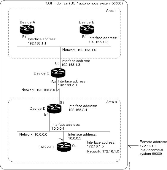
In this configuration, five devices are configured in OSPF autonomous system 1:
-
Device A and Device B are both internal devices within area 1.
-
Device C is an OSPF ABR. Note that for Device C, area 1 is assigned to E3 and Area 0 is assigned to S0.
-
Device D is an internal device in area 0 (backbone area). In this case, both
network router configuration commands specify the same area (area 0, or the backbone area). -
Device E is an OSPF ASBR. Note that the Border Gateway Protocol (BGP) routes are redistributed into OSPF and that these routes
are advertised by OSPF.
|
Note |
Definitions of all areas in an OSPF autonomous system need not be included in the configuration of all devices in the autonomous |
Autonomous system 60000 is connected to the outside world via the BGP link to the external peer at IP address 172.16.1.6.
Following is the sample configuration for the general network map shown in the figure above.
Device A Configuration—Internal Device
Device(config)# interface GigabitEthernet 1/0/0
Device(config-if)# ip address 192.168.1.1 255.255.255.0
Device(config-if)# exit
Device(config)# router ospf 1
Device(config-router)# network 192.168.1.0 0.0.0.255 area 1
Device(config-router)# exit
Device B Configuration—Internal Device
Device(config)# interface GigabitEthernet 2/0/0
Device(config-if)# ip address 192.168.1.2 255.255.255.0
Device(config-if)# exit
Device(config)# router ospf 1
Device(config-router)# network 192.168.1.0 0.0.0.255 area 1
Device(config-router)# exit
Device C Configuration—ABR
Device(config)# interface GigabitEthernet 3/0/0
Device(config-if)# ip address 192.168.1.3 255.255.255.0
Device(config-if)# exit
Device(config)# interface Serial 0/0/0
Device(config-if)# ip address 192.168.2.3 255.255.255.0
Device(config-if)# exit
Device(config)# router ospf 1
Device(config-router)# network 192.168.1.0 0.0.0.255 area 1
Device(config-router)# network 192.168.2.0 0.0.0.255 area 0
Device(config-router)# exit
Device D Configuration—Internal Device
Device(config)# interface GigabitEthernet 4/0/0
Device(config-if)# ip address 10.0.0.4 255.0.0.0
Device(config-if)# exit
Device(config)# interface Serial 1/0/0
Device(config-if)# ip address 192.168.2.4 255.255.255.0
Device(config-if)# exit
Device(config)# router ospf 1
Device(config-router)# network 192.168.2.0 0.0.0.255 area 0
Device(config-router)# network 10.0.0.0 0.255.255.255 area 0
Device(config-router)# exit
Device E Configuration—ASBR
Device(config)# interface GigabitEthernet 5/0/0
Device(config-if)# ip address 10.0.0.5 255.0.0.0
Device(config-if)# exit
Device(config)# interface Serial 2/0/0
Device(config-if)# ip address 172.16.1.5 255.255.255.0
Device(config-if)# exit
Device(config)# router ospf 1
Device(config-router)# network 10.0.0.0 0.255.255.255 area 0
Device(config-router)# redistribute bgp 50000 metric 1 metric-type 1
Device(config-router)# exit
Device(config)# router bgp 50000
Device(config-router)# network 192.168.0.0
Device(config-router)# network 10.0.0.0
Device(config-router)# neighbor 172.16.1.6 remote-as 60000
Example: Complex OSPF Configuration
The following sample configuration accomplishes several tasks in setting up an ABR. These tasks can be split into two general
categories:
-
Basic OSPF configuration
-
Route redistribution
The specific tasks outlined in this configuration are detailed briefly in the following descriptions. The figure below illustrates
the network address ranges and area assignments for the interfaces.

The basic configuration tasks in this example are as follows:
-
Configure address ranges for Gigabit Ethernet interface 0/0/0 through Gigabit Ethernet interface 3/0/0.
-
Enable OSPF on each interface.
-
Set up an OSPF authentication password for each area and network.
-
Assign link-state metrics and other OSPF interface configuration options.
-
Create a stub area with area ID 10.0.0.0. (Note that the
authentication and
stub options of the
area router configuration command are specified with separate
area command entries, but they can be merged into a single
area command.) -
Specify the backbone area (area 0).
Configuration tasks associated with redistribution are as follows:
-
Redistribute the Enhanced Interior Gateway Routing Protocol (EIGRP) and the Routing Information Protocol (RIP) into OSPF
with various options set (including metric-type, metric, tag, and subnet). -
Redistribute EIGRP and OSPF into RIP.
The following is an example OSPF configuration:
Device(config)# interface GigabitEthernet 0/0/0
Device(config-if)# ip address 192.168.110.201 255.255.255.0
Device(config-if)# ip ospf authentication-key abcdefgh
Device(config-if)# ip ospf cost 10
Device(config-if)# exit
Device(config)# interface GigabitEthernet 1/0/0
Device(config-if)# ip address 172.19.251.201 255.255.255.0
Device(config-if)# ip ospf authentication-key ijklmnop
Device(config-if)# ip ospf cost 20
Device(config-if)# ip ospf retransmit-interval 10
Device(config-if)# ip ospf transmit-delay 2
Device(config-if)# ip ospf priority 4
Device(config-if)# exit
Device(config)# interface GigabitEthernet 2/0/0
Device(config-if)# ip address 172.19.254.201 255.255.255.0
Device(config-if)# ip ospf authentication-key abcdefgh
Device(config-if)# ip ospf cost 10
Device(config-if)# exit
Device(config)# interface GigabitEthernet 3/0/0
Device(config-if)# ip address 10.56.0.201 255.255.0.0
Device(config-if)# ip ospf authentication-key ijklmnop
Device(config-if)# ip ospf cost 20
Device(config-if)# ip ospf dead-interval 80
Device(config-if)# exit
In the following configuration, OSPF is on network 172.19.0.0:
Device(config)# router ospf 1
Device(config-router)# network 10.0.0.0 0.255.255.255 area 10.0.0.0
Device(config-router)# network 192.168.110.0 0.0.0.255 area 192.168.110.0
Device(config-router)# network 172.19.0.0 0.0.255.255 area 0
Device(config-router)# area 0 authentication
Device(config-router)# area 10.0.0.0 stub
Device(config-router)# area 10.0.0.0 authentication
Device(config-router)# area 10.0.0.0 default-cost 20
Device(config-router)# area 192.168.110.0 authentication
Device(config-router)# area 10.0.0.0 range 10.0.0.0 255.0.0.0
Device(config-router)# area 192.168.110.0 range 192.168.110.0 255.255.255.0
Device(config-router)# area 0 range 172.19.251.0 255.255.255.0
Device(config-router)# area 0 range 172.19.254.0 255.255.255.0
Device(config-router)# redistribute eigrp 200 metric-type 2 metric 1 tag 200 subnets
Device(config-router)# redistribute rip metric-type 2 metric 1 tag 200
Device(config-router)# exit
In the following configuration, EIGRP autonomous system 1 is on 172.19.0.0:
Device(config)# router eigrp 1
Device(config-router)# network 172.19.0.0
Device(config-router)# exit
Device(config)# ! RIP for 192.168.110.0:
Device(config)# router rip
Device(config-router)# network 192.168.110.0
Device(config-router)# redistribute eigrp 1 metric 1
Device(config-router)# redistribute ospf 201 metric 1
Device(config-router)# exit
Example: Default Metric Values Redistribution
The following example shows a device in autonomous system 1 that is configured to run both the Routing Information Protocol
(RIP) and the Enhanced Interior Gateway Routing Protocol (EIGRP). The example advertises EIGRP-derived routes using RIP and
assigns the EIGRP-derived routes a RIP metric of 10.
Device(config)# router rip
Device(config-router)# redistribute eigrp 1
Device(config-router)# default-metric 10
Device(config-router)# exit
Examples: Redistribution With and Without Route Maps
The examples in this section illustrate the use of redistribution, with and without route maps. Examples from both the IP
and Connectionless Network Service (CLNS) routing protocols are given. The following example redistributes all Open Shortest
Path First (OSPF) routes into the Enhanced Interior Gateway Routing Protocol (EIGRP):
Device(config)# router eigrp 1
Device(config-router)# redistribute ospf 101
Device(config-router)# exit
The following example redistributes Routing Information Protocol (RIP) routes with a hop count equal to 1 into OSPF. These
routes will be redistributed into OSPF as external link state advertisements (LSAs) with a metric of 5, metric a type of type
1, and a tag equal to 1.
Device(config)# router ospf 1
Device(config-router)# redistribute rip route-map rip-to-ospf
Device(config-router)# exit
Device(config)# route-map rip-to-ospf permit
Device(config-route-map)# match metric 1
Device(config-route-map)# set metric 5
Device(config-route-map)# set metric-type type 1
Device(config-route-map)# set tag 1
Device(config-route-map)# exit
The following example redistributes OSPF learned routes with tag 7 as a RIP metric of 15:
Device(config)# router rip
Device(config-router)# redistribute ospf 1 route-map 5
Device(config-router)# exit
Device(config)# route-map 5 permit
Device(config-route-map)# match tag 7
Device(config-route-map)# set metric 15
The following example redistributes OSPF intra-area and interarea routes with next hop devices on serial interface 0/0/0
into the Border Gateway Protocol (BGP) with an INTER_AS metric of 5:
Device(config)# router bgp 50000
Device(config-router)# redistribute ospf 1 route-map 10
Device(config-router)# exit
Device(config)# route-map 10 permit
Device(config-route-map)# match route-type internal
Device(config-route-map)# match interface serial 0/0/0
Device(config-route-map)# set metric 5
The following example redistributes two types of routes into the integrated IS-IS routing table (supporting both IP and CLNS).
The first type is OSPF external IP routes with tag 5; these routes are inserted into Level 2 IS-IS link-state packets (LSPs)
with a metric of 5. The second type is ISO-IGRP derived CLNS prefix routes that match CLNS access list 2000; these routes
will be redistributed into IS-IS as Level 2 LSPs with a metric of 30.
Device(config)# router isis
Device(config-router)# redistribute ospf 1 route-map 2
Device(config-router)# redistribute iso-igrp nsfnet route-map 3

Device(config-router)# exit
Device(config)# route-map 2 permit
Device(config-route-map)# match route-type external
Device(config-route-map)# match tag 5
Device(config-route-map)# set metric 5
Device(config-route-map)# set level level-2
Device(config-route-map)# exit
Device(config)# route-map 3 permit
Device(config-route-map)# match address 2000
Device(config-route-map)# set metric 30
Device(config-route-map)# exit
With the following configuration, OSPF external routes with tags 1, 2, 3, and 5 are redistributed into RIP with metrics of
1, 1, 5, and 5, respectively. The OSPF routes with a tag of 4 are not redistributed.
Device(config)# router rip
Device(config-router)# redistribute ospf 101 route-map 1
Device(config-router)# exit
Device(config)# route-map 1 permit
Device(config-route-map)# match tag 1 2
Device(config-route-map)# set metric 1
Device(config-route-map)# exit
Device(config)# route-map 1 permit
Device(config-route-map)# match tag 3
Device(config-route-map)# set metric 5
Device(config-route-map)# exit
Device(config)# route-map 1 deny
Device(config-route-map)# match tag 4
Device(config-route-map)# exit
Device(config)# route map 1 permit
Device(config-route-map)# match tag 5
Device(config-route-map)# set metric 5
Device(config-route-map)# exit
Given the following configuration, a RIP learned route for network 172.18.0.0 and an ISO-IGRP learned route with prefix 49.0001.0002
will be redistributed into an IS-IS Level 2 LSP with a metric of 5:
Device(config)# router isis
Device(config-router)# redistribute rip route-map 1
Device(config-router)# redistribute iso-igrp remote route-map 1
Device(config-router)# exit
Device(config)# route-map 1 permit
Device(config-route-map)# match ip address 1
Device(config-route-map)# match clns address 2
Device(config-route-map)# set metric 5
Device(config-route-map)# set level level-2
Device(config-route-map)# exit
Device(config)# access-list 1 permit 172.18.0.0 0.0.255.255
Device(config)# clns filter-set 2 permit 49.0001.0002...
The following configuration example illustrates how a route map is referenced by the
default-information router configuration command. This type of reference is called conditional default origination. OSPF will originate the default
route (network 0.0.0.0) with a type 2 metric of 5 if 172.20.0.0 is in the routing table.
Device(config)# route-map ospf-default permit
Device(config-route-map)# match ip address 1
Device(config-route-map)# set metric 5
Device(config-route-map)# set metric-type type-2
Device(config-route-map)# exit
Device(config)# access-list 1 172.20.0.0 0.0.255.255
Device(config)# router ospf 101
Device(config-router)# default-information originate route-map ospf-default
Examples: Key Management
The following example configures a key chain named chain1. In this example, the software always accepts and sends key1 as
a valid key. The key key2 is accepted from 1:30 p.m. to 3:30 p.m. and is sent from 2:00 p.m. to 3:00 p.m. The overlap allows
for migration of keys or discrepancy in the set time of the device. Likewise, the key key3 immediately follows key2, and there
is 30-minutes on each side to handle time-of-day differences.
Device(config)# interface GigabitEthernet 0/0/0
Device(config-if)# ip rip authentication key-chain chain1
Device(config-if)# ip rip authentication mode md5
Device(config-if)# exit
Device(config)# router rip
Device(config-router)# network 172.19.0.0
Device(config-router)# version 2
Device(config-router)# exit
Device(config)# key chain chain1
Device(config-keychain)# key 1
Device(config-keychain-key)# key-string key1
Device(config-keychain-key)# exit
Device(config-keychain)# key 2
Device(config-keychain-key)# key-string key2
Device(config-keychain-key)# accept-lifetime 13:30:00 Jan 25 2005 duration 7200
Device(config-keychain-key)# send-lifetime 14:00:00 Jan 25 2005 duration 3600
Device(config-keychain-key)# exit
Device(config-keychain)# key 3
Device(config-keychain-key)# key-string key3
Device(config-keychain-key)# accept-lifetime 14:30:00 Jan 25 2005 duration 7200
Device(config-keychain-key)# send-lifetime 15:00:00 Jan 25 2005 duration 3600
Device(config-keychain-key)# end
The following example configures a key chain named chain1:
Device(config)# key chain chain1
Device(config-keychain)# key 1
Device(config-keychain-key)# key-string key1
Device(config-keychain-key)# exit
Device(config-keychain)# key 2
Device(config-keychain-key)# key-string key2
Device(config-keychain-key)# accept-lifetime 00:00:00 Dec 5 2004 23:59:59 Dec 5 2005
Device(config-keychain-key)# send-lifetime 06:00:00 Dec 5 2004 18:00:00 Dec 5 2005
Device(config-keychain-key)# exit
Device(config-keychain)# exit
Device(config)# interface GigabitEthernet 0/0/0
Device(config-if)# ip address 172.19.104.75 255.255.255.0 secondary 172.19.232.147 255.255.255.240
Device(config-if)# ip rip authentication key-chain chain1
Device(config-if)# media-type 10BaseT
Device(config-if)# exit
Device(config)# interface GigabitEthernet 1/0/0
Device(config-if)# no ip address
Device(config-if)# shutdown
Device(config-if)# media-type 10BaseT
Device(config-if)# exit
Device(config)# interface Fddi 0
Device(config-if)# ip address 10.1.1.1 255.255.255.0
Device(config-if)# no keepalive
Device(config-if)# exit
Device(config)# interface Fddi 1/0/0
Device(config-if)# ip address 172.16.1.1 255.255.255.0
Device(config-if)# ip rip send version 1
Device(config-if)# ip rip receive version 1
Device(config-if)# no keepalive
Device(config-if)# exit
Device(config)# router rip
Device(config-router)# version 2
Device(config-router)# network 172.19.0.0
Device(config-router)# network 10.0.0.0
Device(config-router)# network 172.16.0.0
Additional References
Related Documents
|
Related |
Document |
|---|---|
|
IP |
|
Technical Assistance
|
Description |
Link |
|---|---|
|
The Cisco |
http://www.cisco.com/cisco/web/support/index.html |
Feature Information for Basic
IP Routing
The following table provides release information about the feature or features described in this module. This table lists
only the software release that introduced support for a given feature in a given software release train. Unless noted otherwise,
subsequent releases of that software release train also support that feature.
Use Cisco Feature Navigator to find information about platform support and Cisco software image support. To access Cisco
Feature Navigator, go to www.cisco.com/go/cfn. An account on Cisco.com is not required.
Время на прочтение
11 мин
Количество просмотров 14K
Сегодня мы поговорим о статической маршрутизации и рассмотрим три темы: что такое статическая маршрутизация, как она настраивается и какая у неё альтернатива. Вы видите топологию сети, которая включает в себя компьютер с IP-адресом 192.168.1.10, подсоединенный через свитч к шлюзу, или роутеру. Для этого соединения используется порт роутера f0/0 с IP-адресом 192.168.1.1.

Второй порт этого роутера f0/1 с IP-адресом 192.168.2.1 подключен к порту f0/0 другого роутера, и этот интерфейс имеет адрес 192.168.2.2. Второй роутер соединен портом f0/1 с адресом 192.168.3.2 с третьим роутером, который использует для этого соединения порт f0/0 с IP-адресом 192.168.3.3.
Наконец, третий роутер соединен со вторым свитчем через порт f0/1 с адресом 192.168.4.3, а свитч подсоединен ко второму компьютеру с IP-адресом 192.168.4.10.
Если вы знаете, как по IP-адресам можно разделить подсети, то определите, что участок от первого компьютера до первого роутера относится к одной подсети, участок межу первым и вторым роутером – ко второй сети, между вторым и третьим роутером – к третьей сети и между третьим роутером и вторым компьютером – к четвертой сети. Таким образом, у нас имеется 4 различных сети.

Если компьютер 192.168.1.10 хочет связаться с компьютером 192.168.4.10, то сначала он должен послать свои данные шлюзу 192.168.1.1. Он создает фрейм, в который помещает IP-адрес источника и назначения, MAC-адрес источника и назначения и отсылает его роутеру. Тот отбрасывает информацию 2-го уровня, то есть MAC-адреса, и смотрит на информацию 3-го уровня. Узнав, что данные адресованы устройству с IP-адресом 192.168.4.10, роутер понимает, что такое устройство к нему не подсоединено, поэтому он просто должен пропустить этот фрейм через себя дальше по сети. Он обращается к своей таблице маршрутизации и видит, что данные для сети 4. нужно посылать устройству с IP-адресом 192.168.2.2.
Аналогично второй роутер сверяется со своей таблицей маршрутизации, узнает, что данные для сети 4. нужно отправить на IP-адрес 192.168.3.3, и отправляет фрейм третьему роутеру. Наконец, третий роутер сверяется со своей таблицей, определяет, что сеть 4. подсоединена к нему самому, и отправляет фрейм второму компьютеру.
Давайте рассмотрим, как создается таблица маршрутизации. Для этого используем Cisco Packet Tracer и посмотрим, как реализуется концепция роутинга. Здесь изображена та же топология сети, и сейчас я присвою роутерам соответствующие IP-адреса, указав также адреса шлюзов по умолчанию.
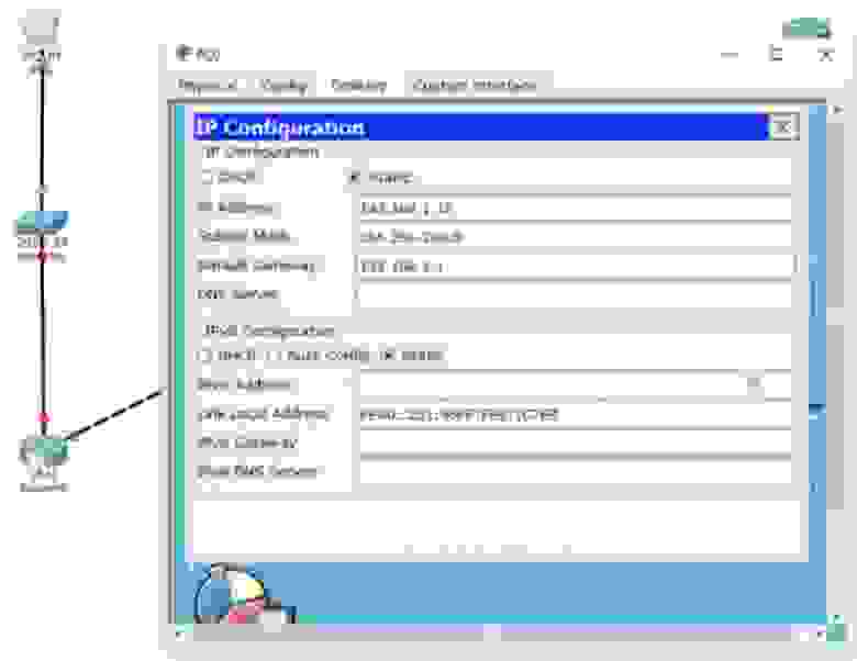
Мы ничего не делаем со свитчем, потому что он работает с настройками по умолчанию и использует VLAN1. Приступим к настройкам первого роутера Router0. Сначала присвоим ему имя хоста R1, после чего пропишем IP-адрес и маску подсети для интерфейса f0/0. Затем нужно применить команду no shutdown. Вы видите, как маркер интерфейса сменился с красного на зеленый, то есть порт включился в сеть.
Далее нам нужно настроить второй порт роутера f0/1, при этом имя хоста остается прежним, мы просто добавляем IP-адрес 192.168.2.1 и маску подсети 255.255.255.0. Здесь нет ничего нового, это простая настройка, вы уже знаете все команды, поэтому я быстро пробегусь по остальным роутерам. По мере того, как я буду присваивать IP-адреса и использовать команду no shut, порты роутеров будут изменять цвет на зеленый, показывая, что связь между устройствами установлена. При этом я создаю сети 1., 2., 3. и 4. Последний октет IP-адреса порта роутера указывает на номер самого роутера, а предпоследний октет – на номер сети, подключенной к этому порту.
Таким образом, у первого роутера адреса портов будут 192.168.1.1 (первый роутер, первая сеть) и 192.168.2.1 (первый роутер, вторая сеть), у второго роутера — 192.168.2.2 (второй роутер, вторая сеть) и 192.168.3.2 (второй роутер, третья сеть) и у третьего роутера — 192.168.3.3 (третий роутер, третья сеть) и 192.168.4.3 (третий роутер, четвертая сеть). По-моему, это довольно легко запомнить, однако в реальности адреса могут формироваться по-другому, в зависимости от правил, принятых в вашей компании. Вы должны придерживаться правил компании, потому что вашему коллеге будет легче устранять неисправности в вашей сети, если вы будете формировать ее в соответствии с правилами.
Итак, я закончил присваивать портам роутера IP-адреса, и вы видите, что порт второго свитча также поменял цвет на зеленый, так как соединение между ним и вторым компьютером создалось автоматически.

Теперь я вызову терминал командной строки первого компьютера и пропингую второй компьютер по адресу 192.168.4.10. Перейдем к режиму симуляции – теперь вы видите анимированное движение пакетов пинга по участкам сети. Сейчас я ещё раз запущу пингование, чтобы вы смогли внимательно посмотреть, что при этом происходит. Справа в таблице вы видите ICMP, Internet Control Message Protocol – так обозначается пинг. Пинг – это протокол, который мы используем для проверки соединения.

Вы посылаете тестовый пакет на другое устройство, и если оно его возвращает, то связь успешно установлена. Если щелкнуть по пакету пинга на схеме, можно посмотреть информацию о передаче.
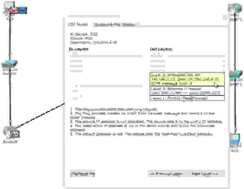
Вы видите данные 3 уровня OSI – это IP-адреса источника и назначения пинга, данные 2-го уровня в виде соответствующих MAC-адресов и данные 1-го уровня в виде обозначения порта (портов) – это FastEthernet0. Вы также можете взглянуть на формат фрейма пинга: заголовок, тип и тело пакета.

Фрейм направляется к свитчу, свитч анализирует MAC-адреса и отправляет его дальше по сети роутеру. Роутер видит IP-адрес 192.168.4.10 и отбрасывает пакет, потому что не знает такого адреса. Давайте посмотрим, что происходит в режиме реального времени, для чего вернемся к пингу в окне командной строки.
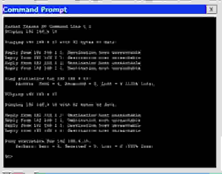
Вы видите, что попытке пропинговать компьютер 192.168.4.10 все 4 пакета были потеряны – от роутера 192.168.1.1 был получен ответ, что хост назначения не доступен. Вернемся в окно интерфейса командной строки роутера и введем команду show ip route. Вы видите самую важную часть – таблицу маршрутизации, а введенная мной команда это одна из основных команд роутинга Cisco. В настоящий момент эта таблица содержит 2 записи. В начале таблицы находится список используемых сокращений, из которого видно, что буквой С обозначаются соединения. Первая запись сообщает, что сеть 192.168.1.0/24 напрямую подсоединена к порту FastEthernet0/0, а сеть 192.168.2.0/24 напрямую подсоединена к порту FastEthernet0/1. Это значит, что в данный момент роутер знает только эти две сети.

Значение 192.168.1.0/24 является идентификатором сети. Когда мы создавали подсети, мы одновременно создавали их идентификаторы. Эти идентификаторы говорят роутеру, что все устройства, IP-адреса которых находятся в диапазоне от 192.168.1.1 до 192.168.1.254, расположены в данной подсети. Таким образом, все эти устройства технически должны быть доступны для роутера, поскольку он подсоединен к данной сети.
Если в конце идентификатора расположено значение /24, это означает, что всем устройствам данной сети от 1 до 254-го будет рассылаться широковещательный запрос. Итак, к данному роутеру подсоединены только сети 1. и 2., поэтому он знает только об этих сетях. Поэтому когда пинг с адресом 192.168.4.10 попадает к роутеру, он не знает, что этот адрес доступен по маршруту Router0- Router1- Router2.
Но вы как администратор сети знаете, что этот маршрут доступен, то есть что первый роутер может отправить этот пакет второму роутеру. Поэтому вы должны организовать статическую маршрутизацию. Давайте попробуем это сделать.
Мы скажем этому роутеру, что любой пакет и любой трафик, предназначенный для сети 192.168.4.0/24, должен быть отправлен второму роутеру. Формат команды для назначения статической маршрутизации имеет такой вид: ip route <идентификатор сети> < IP-адрес маски подсети > < IP-адрес шлюза >.

Сейчас я покажу вам, что это означает. Мы используем для этой команды режим глобальной конфигурации настроек роутера. Я набираю ip route 192.168.4.0 255.255.255.0 – это означает, что сюда попадает любой трафик для устройств сети, чей IP-адрес имеет значение последнего октета от 1 до 254, и далее набираю либо IP-адрес, либо обозначение порта, куда должен отправляться этот трафик. В данном случае я набираю обозначение интерфейса f0/1, то есть команда приобретает такой вид: ip route 192.168.4.0 255.255.255.0 f0/1.

Вместо интерфейса шлюза я могу указать его IP-адрес, тогда команда статической маршрутизации будет выглядеть как ip route 192.168.4.0 255.255.255.0 192.168.2.2.
Вы можете спросить, что лучше. Я думаю, что для широковещательных сетей, таких, как Ethernet, лучше указывать IP-адрес. Если же вы используете сети типа «точка-точка», такие, как Frame Relay (сети с ретрансляцией, или коммутацией кадров), лучше использовать exit interface. Позже мы рассмотрим сети Frame Relay, сейчас же я использую более подходящий вариант команды маршрутизации -192.168.4.0 255.255.255.0.
Давайте теперь посмотрим на таблицу маршрутизации, использовав команду do show ip address. Вы видите, что в ней появилась новая запись, озаглавленная буквой S, то есть static.
Эта запись говорит о том, что если имеется трафик для сети 192.168.4.0/24, его нужно пересылать адресату через устройство с IP-адресом 192.168.2.2. Вернемся к командной строке компьютера и пропингуем нужный адрес еще раз. Теперь трафик должен пройти через первый роутер и достигнуть второго роутера, который должен отбросить пакеты.
В первом случае роутер не просто отбросил пакеты, он еще и ответил компьютеру, что IP-адрес 192.168.4.10 недоступен. Однако второй роутер может ответить только первому роутеру, от которого получил трафик. Давайте посмотрим на таблицу маршрутизации второго роутера. Здесь сказано, что Router1 знает только сети 2. и 3. и ничего не знает о сети 4., куда он должен отправить пакеты первого компьютера. Он бы отправил назад сообщение, что хост назначения не доступен, но не знает, как связаться с компьютером, который послал эти пакеты, потому что ничего не знает о сети 1. Вот почему вместо сообщения о недоступности хоста назначения мы получили сообщение Request timed out – время ожидания запроса истекло. Различные сетевые устройства имеют различные значения TTL, поэтому, когда IP пакеты достигают этого значения, они уничтожаются. При этом происходит обратный отсчет – совершается один хоп, и счетчик TTL меняется с 16 до 15, второй – с 15 до 14 и так далее, пока значение TTL не достигнет 0 и пакет будет уничтожен.
Так работает механизм предотвращения зацикленности IP-пакетов. Таким образом, если устройство не получает запрос в установленное время, система выдаёт подобное сообщение. Поэтому давайте перейдем к настройкам второго роутера и покажем ему, как можно достичь четвертой подсети. Для этого я использую команду ip route 192.168.4.0 255.255.255.0 192.168.3.3. Теперь соответствующая запись появилась в таблице маршрутизации, которую мы вызвали командой do show ip route.
Теперь Router1 знает, как отправлять трафик адресатам четвертой подсети. Он отправляет его третьему роутеру. Третий роутер Router2, поскольку к нему подсоединена сеть 4., определенно знает, как отправить пакет второму компьютеру.
Что произойдет, если я еще раз отправлю пинг? Ведь теперь все сетевые устройства знают, как достичь второго компьютера. Будет ли теперь пингование IP-адреса 192.168.4.10 удачным? Нет, не будет!
Как я уже говорил, ICMP представляет собой протокол двусторонней коммуникации, поэтому, если кто-то посылает пакеты пинга, они должны вернуться обратно. Маршрутизация заключается в том, что каждое сетевое устройство должно не только знать, как отправить кому-либо сообщение, оно также должно знать, как доставить ответное сообщение отправителю запроса. Итак, пакет, отправленный первым компьютером, успешно достиг второго компьютера. Второй компьютер думает: «отлично, я получил ваше сообщение и теперь должен выслать вам ответ». Этот ответ, адресованный устройству с IP-адресом 192.168.1.10, добирается до роутера Router2. Третий роутер видит, что должен отправить пакет в первую подсеть, но в его таблице маршрутизации есть записи только о третьей и четвертой подсети. Поэтому мы должны создать статический маршрут с помощью команды ip route 192.168.1.0 255.255.255.0 192.168.3.2. Данная команда говорит, что трафик, предназначенный для сети с идентификатором 192.168.1.0 должен быть отправлен второму роутеру с IP-адресом 192.168.3.2.
Что произойдет после этого? Второй роутер знает про сети 2., 3. и 4., но ничего не знает о первой сети. Поэтому нужно зайти в настройки второго роутера Router1 и использовать команду ip route 192.168.1.0 255.255.255.0 192.168.2.1, то есть указать, что трафик для сети 1. должен быть отправлен по сети 2. первому роутеру Router0.
После этого пакет достигает первого роутера, который знает об устройстве 192.168.1.10, потому что первая сеть, в которой находится этот компьютер, подключена к порту этого роутера. Замечу, что теперь первый роутер ничего не знает о сети 3., а третий роутер ничего не знает о второй сети. Это может создать проблему, потому что эти роутеры не знают о существовании промежуточных подсетей.
Я еще раз пингую адрес 192.168.4.0, и вы видите, что на этот раз пингование прошло успешно. Пакеты прошли весь путь от первого до второго компьютера и ответ вернулся отправителю. В окне командной строки видно сообщение о том, что каждый из 4-х ответных пакетов 192.168.4.0 представляет собой 32 байта, TTL= 125 мс, и успешность пинга составляет 100%. Это означает, что источник передачи получил ответ от хоста назначения. Таким образом, даже если устройства не знают о существовании некоторых промежуточных сетей, это не имеет значения, если они работают по принципу «конечный отправитель – конечный получатель». Первый компьютер знает, как добраться до второго компьютера, а второй – как добраться до первого.
Давайте рассмотрим другую ситуацию. Итак, первый компьютер может успешно общаться со вторым компьютером, при этом трафик проходит через все эти устройства. Посмотрим, сможет ли PC0 связаться с третьим роутером Router2 по адресу 192.168.3.3 – это порт сети 3 третьего роутера. Пинг показывает, что это невозможно – хост назначения недоступен.
Посмотрим, в чем причина. Открыв таблицу маршрутизации первого роутера, мы видим, что он знает только 3 сети – первую, вторую и четвертую, но ничего не знает о третьей сети. Поэтому, если я хочу связаться с этой сетью, для неё нужно задать статический маршрут.
Итак, мы рассмотрели, как можно настроить статическую маршрутизацию для трех роутеров. Если у вас имеется 10 роутеров и 50 различных подсетей, ручная настройка статической маршрутизации займет очень много времени. Вот зачем нам нужна динамическая маршрутизация.
Сейчас я удалю все маршруты, которые создал. Для этого я поочередно вызову таблицы маршрутизации всех роутеров и допишу слово «no» в начале каждой записи статической маршрутизации, то есть использую команду отрицания. Теперь мы можем рассмотреть, что представляет собой динамическая маршрутизация.
Для динамической маршрутизации я должен активировать протокол RIP, это очень быстрый протокол. Но сегодня мы не будем обсуждать RIP, наша тема – это статическая маршрутизация, и я хотел показать вам, насколько это кропотливое и утомительное дело. Я все же быстро продемонстрирую вам, как работает RIP, который мы подробно рассмотрим на следующем уроке.
На примере первого роутера я использую команду router rip, затем введу ver 2, чтобы указать версию протокола, и затем отдельными строками перечислю сети, для которых нужно использовать протокол динамической маршрутизации: 192.168.1.0, 192.168.2.0, после чего перейду ко второму роутеру и поступлю с ним аналогично. Технически я просто указываю сети, которые подключены к данному устройству, поэтому для второго роутера я укажу 192.168.2.0 и 192.168.3.0, а для третьего после команды rip ver 2 – адреса 192.168.3.0 и 192.168.4.0. Затем я вернусь к первому роутеру и посмотрю на таблицу маршрутизации.

Вы видите, что в ней волшебным образом появились все сети, две первые – это те, что подсоединены непосредственно к роутеру, а две остальные – те, связь с которыми осуществляется по протоколу динамической маршрутизации RIP. Аналогичная ситуация наблюдается в таблицах маршрутизации второго и третьего роутеров. Если я подсоединю ко второму роутеру сети 5. и 6., то все устройства, использующие RIP, будут знать об этих новых сетях. Вот в чем заключается преимущество динамической маршрутизации.

Если я сейчас пропингую второй компьютер, связь будет работать без проблем. Я могу пропинговать третий роутер, и пинг будет успешным, потому что первый роутер благодаря RIP знает обо всех устройствах всех сетей. Аналогичным «знанием» будут обладать второй и третий роутеры. Я не говорю, что RIP самый лучший протокол, но он способен эффективно выполнять множество вещей. Пока что я просто хочу, чтобы вы поняли, что такое маршрутизация и как она работает, что такое таблица маршрутизации и в чем заключено её значение.
Независимо от того, используете вы статическую или динамическую маршрутизацию, роль протоколов заключается в том, чтобы заполнить таблицу маршрутизации. Эта таблица должна знать обо всех маршрутах ко всем устройствам сети, чтобы одно устройство могло установить соединение с другим устройством.
Итак, сегодня вы узнали, что маршрутизация – это процесс, обеспечивающий появление записей о маршрутах в таблицах маршрутизации для того, чтобы роутер мог принять решение об отправке трафика по сети.
Спасибо, что остаётесь с нами. Вам нравятся наши статьи? Хотите видеть больше интересных материалов? Поддержите нас оформив заказ или порекомендовав знакомым, 30% скидка для пользователей Хабра на уникальный аналог entry-level серверов, который был придуман нами для Вас: Вся правда о VPS (KVM) E5-2650 v4 (6 Cores) 10GB DDR4 240GB SSD 1Gbps от $20 или как правильно делить сервер? (доступны варианты с RAID1 и RAID10, до 24 ядер и до 40GB DDR4).
Dell R730xd в 2 раза дешевле? Только у нас 2 х Intel TetraDeca-Core Xeon 2x E5-2697v3 2.6GHz 14C 64GB DDR4 4x960GB SSD 1Gbps 100 ТВ от $199 в Нидерландах! Dell R420 — 2x E5-2430 2.2Ghz 6C 128GB DDR3 2x960GB SSD 1Gbps 100TB — от $99! Читайте о том Как построить инфраструктуру корп. класса c применением серверов Dell R730xd Е5-2650 v4 стоимостью 9000 евро за копейки?
Table of Contents
1
Routers cannot forward data (IP packets) destined for networks that are not registered in the routing table and discard them.
Therefore, it is a prerequisite that the routing tables of all the routers on the network have the correct and complete route information for all the networks to which you want to forward data.
Static route is a configuration method in which route information (network address/subnet mask, next hop) is registered by entering commands for each router. It is not possible to configure correctly unless you have a good grasp of the network that should be registered in the routing table for each router based on the overall image of the network. Also, the fact that communication is bi-directional must be taken into consideration when making configurations.
The commands for configuring static routes on Cisco routers are explained in the following article.
We will proceed step by step to configure a static route with the following simple network diagram. Even with a simple network diagram, communication will not be successful unless you properly consider the static route configuration.
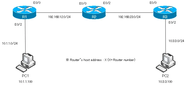
When only IP addresses are configured in R1 to R3, only the route information about the directly connected network of each router is registered in the routing table.
R1
R1#show ip route
- ommitted -

Gateway of last resort is not set

C    192.168.12.0/24 is directly connected, Ethernet0/0
     10.0.0.0/24 is subnetted, 1 subnets
C       10.1.1.0 is directly connected, Ethernet0/2
R2
R2#show ip route
- ommitted -

Gateway of last resort is not set

C    192.168.12.0/24 is directly connected, Ethernet0/0
C    192.168.23.0/24 is directly connected, Ethernet0/2
R3
R3#show ip route
- ommitted -

Gateway of last resort is not set

     10.0.0.0/24 is subnetted, 1 subnets
C       10.3.3.0 is directly connected, Ethernet0/2
C    192.168.23.0/24 is directly connected, Ethernet0/0
From the routing table, we can see that the following four networks are interconnected by R1 to R3.
| Network address | Connecting router |
| 10.1.1.0/24 | R1 |
| 192.168.12.0/24 | R1/R2 |
| 192.168.23.0/24 | R2/R3 |
| 10.3.3.0/24 | R3 |
However, if the IP address are configured and only the route information of the directly connected network is in the routing table, data cannot be transferred between all networks. For example, a ping from PC1 (10.1.1.100) to PC2 (10.3.3.3) will not get a response.
ping from PC1 to PC2
PC1> ping 10.3.3.100
*10.1.1.1 icmp_seq=1 ttl=255 time=8.114 ms (ICMP type:3, code:1, Destination host unreachable)
*10.1.1.1 icmp_seq=2 ttl=255 time=8.081 ms (ICMP type:3, code:1, Destination host unreachable)
*10.1.1.1 icmp_seq=3 ttl=255 time=11.207 ms (ICMP type:3, code:1, Destination host unreachable)
*10.1.1.1 icmp_seq=4 ttl=255 time=4.270 ms (ICMP type:3, code:1, Destination host unreachable)
*10.1.1.1 icmp_seq=5 ttl=255 time=9.841 ms (ICMP type:3, code:1, Destination host unreachable)
An ICMP echo request for a ping from PC1 to PC2 will be discarded by R1 because R1 does not have the route information to forward to 10.3.3.3.
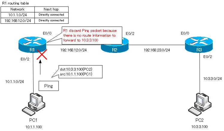
Configure a static route of 10.3.3.0/24 on R1.
Configure a static route to communicate between PC1 and PC2. on R1, configure the route information for 10.3.3.0/24 with the following command. The next hop is R2, i.e. 192.168.12.2.
R1 static route for 10.3.3.0/24
ip route 10.3.3.0 255.255.255.0 192.168.12.2
After configuring the static route for 10.3.3.0/24, the routing table for R1 will look like the following
R1 routing table
R1#show ip route
-- ommitted --

Gateway of last resort is not set

C    192.168.12.0/24 is directly connected, Ethernet0/0
     10.0.0.0/24 is subnetted, 2 subnets
S       10.3.3.0 [1/0] via 192.168.12.2
C       10.1.1.0 is directly connected, Ethernet0/2
Pinging from PC1 to PC2 fails even if I configure a static route of 10.3.3.0/24 only on R1
ping from PC1 to PC2
PC1> ping 10.3.3.100
10.3.3.100 icmp_seq=1 timeout
10.3.3.100 icmp_seq=2 timeout
10.3.3.100 icmp_seq=3 timeout
10.3.3.100 icmp_seq=4 timeout
10.3.3.100 icmp_seq=5 timeout
R1 is forwarding the ping from PC1 to PC2 to R2. But there is no route information matching the destination IP address 10.3.3.100 in R2, so the ping packet from PC1 to PC2 is discarded by R2.
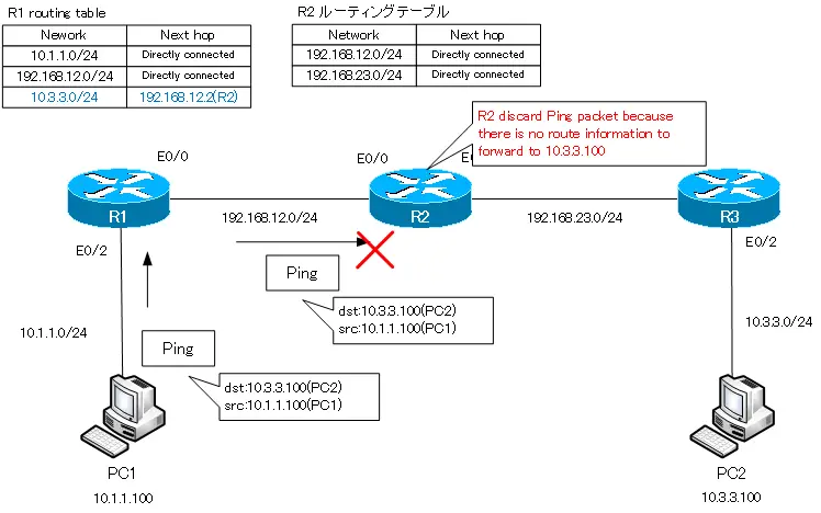
Configure a static route of 10.3.3.0/24 on R2.
We need to configure a static route of 10.3.3.0/24 not only on R1 but also on R2, where the next hop is R3, i.e. 192.168.23.3.
R2 static route of 10.3.3.0/24
ip route 10.3.3.0 255.255.255.0 192.168.23.3
Verifying the routing table on R2, a static route of 10.3.3.0/24 is added.
R2 routing table
R2#show ip route
-- ommitted --

Gateway of last resort is not set

C    192.168.12.0/24 is directly connected, Ethernet0/0
     10.0.0.0/24 is subnetted, 1 subnets
S       10.3.3.0 [1/0] via 192.168.23.3
C    192.168.23.0/24 is directly connected, Ethernet0/2
However, even with a static route of 10.3.3.0/24 on R2, the ping from PC1 to PC2 does not succeed.
ping from PC1 to PC2
PC1> ping 10.3.3.100
10.3.3.100 icmp_seq=1 timeout
10.3.3.100 icmp_seq=2 timeout
10.3.3.100 icmp_seq=3 timeout
10.3.3.100 icmp_seq=4 timeout
10.3.3.100 icmp_seq=5 timeout
With a static route of 10.3.3.0/24 on R1 and R2, an ICMP echo request pinging from PC1 to PC2 is reaching PC2.
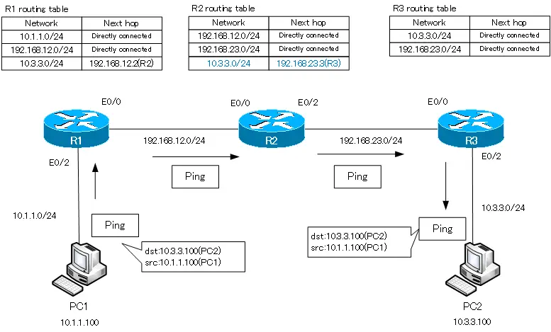
Don’t forget that communication is bi-directional: when PC1 pings PC2 and an ICMP echo request reaches PC2, it replies with an ICMP echo reply. The destination IP address and source IP address of the ICMP echo request are swapped in the ICMP echo reply. The destination is 10.1.1.100 (PC1) and the source is 10.3.3.100 (PC2). R3 has no route information matching the destination 10.1.1.100, so it discards it.
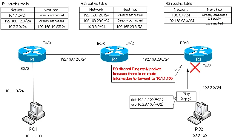
Configure a static route of 10.1.1.0/24 on R3.
To enable PC2 to return a ping reply to PC1, configure R3 with a static route of 10.1.1.0/24 as the route information matching the destination 10.1.1.100.
R3 static route of 10.1.1.0/24
ip route 10.1.1.0 255.255.255.0 192.168.23.2
With this configuration, the static route 10.1.1.0/24 will be registered in the routing table of R3 as follows.
R3 routing table
R3#show ip route
-- ommitted --

Gateway of last resort is not set

     10.0.0.0/24 is subnetted, 2 subnets
C       10.3.3.0 is directly connected, Ethernet0/2
S       10.1.1.0 [1/0] via 192.168.23.2
C    192.168.23.0/24 is directly connected, Ethernet0/0
However, pinging from PC1 to PC2 is still not successful.
ping from PC1 to PC2
PC1> ping 10.3.3.100
10.3.3.100 icmp_seq=1 timeout
10.3.3.100 icmp_seq=2 timeout
10.3.3.100 icmp_seq=3 timeout
10.3.3.100 icmp_seq=4 timeout
10.3.3.100 icmp_seq=5 timeout
When we ping PC1 to PC2, the ICMP echo request is forwarded to PC2. Then, an ICMP echo reply is sent from PC2 to PC1 as a reply. The echo reply is forwarded from R3 to R2, but R2 has no route information matching the destination 10.1.1.100. The ICMP echo reply will be discarded by R2, so the ping will not succeed.
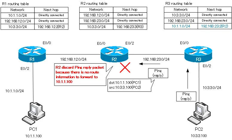
Configure a static route of 10.1.1.0/24 on R2.
Configure a static route for 10.1.1.0/24 on R2 so that it can return an ICMP echo reply in response to an ICMP echo request for a ping from PC1 to PC2.
R2 static route of 10.1.1.0/24
ip route 10.1.1.0 255.255.255.0 192.168.12.1
The static route of 10.1.1.0/24 will be registered in the routing table of R2 as shown below.
R2 routing table
R2#show ip route
-- ommitted --

Gateway of last resort is not set

C    192.168.12.0/24 is directly connected, Ethernet0/0
     10.0.0.0/24 is subnetted, 2 subnets
S       10.3.3.0 [1/0] via 192.168.23.3
S       10.1.1.0 [1/0] via 192.168.12.1
C    192.168.23.0/24 is directly connected, Ethernet0/2
This will finally allow PC1 to successfully ping PC2.
ping from PC1 to PC2
PC1> ping 10.3.3.100
84 bytes from 10.3.3.100 icmp_seq=1 ttl=61 time=55.660 ms
84 bytes from 10.3.3.100 icmp_seq=2 ttl=61 time=63.150 ms
84 bytes from 10.3.3.100 icmp_seq=3 ttl=61 time=66.075 ms
84 bytes from 10.3.3.100 icmp_seq=4 ttl=61 time=57.319 ms
84 bytes from 10.3.3.100 icmp_seq=5 ttl=61 time=61.142 ms
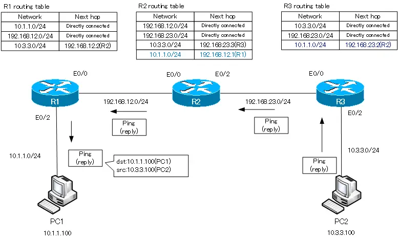
Can’t ping from R1 to R3…
With the static route configuration up to this point, communication between PC1 and PC2 is possible. However, pinging from R1 to R3 will fail.
ping form R1 to R3
R1#ping 192.168.23.3

Type escape sequence to abort.
Sending 5, 100-byte ICMP Echos to 192.168.23.3, timeout is 2 seconds:
.....
Success rate is 0 percent (0/5)
I am getting ping responses between PC1 and PC2, but I am not getting any ping responses between R1 and R3 on that route. If you can easily say, “That’s natural,” then you have the basic principle of routing at the beginning of this article firmly in your mind: when you ping from R1 to 192.168.23.3 on R3, the destination/source IP addresses are as follows
destination IP : 192.168.23.3
source IP : 192.168.12.2
The ICMP echo request for ping cannot be sent because there is no route information matching the destination IP address 192.168.23.3 in the routing table on R1.
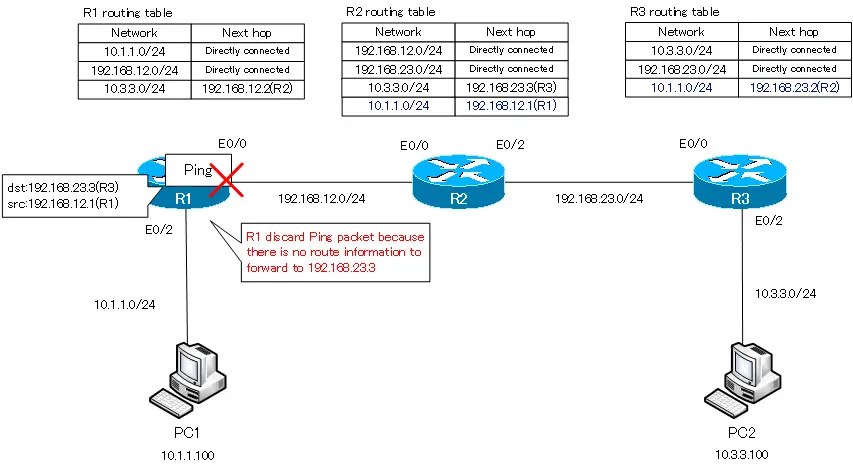
Configure static route 192.168.23.0/24 on R1
To send an ICMP echo request for ping from R1 to R3 (192.168.23.3), add the route information of 192.168.23.0/24 to the routing table on R1.
R1 static route of 192.168.23.0/24
ip route 192.168.23.0 255.255.255.0 192.168.12.2
With this configuration, the static route of 192.168.23.0/24 will be registered in the routing table on R1.
R1 routing table
R1#show ip route
-- omitted --

Gateway of last resort is not set

C    192.168.12.0/24 is directly connected, Ethernet0/0
     10.0.0.0/24 is subnetted, 2 subnets
S       10.3.3.0 [1/0] via 192.168.12.2
C       10.1.1.0 is directly connected, Ethernet0/2
S    192.168.23.0/24 [1/0] via 192.168.12.2
If you just configure a static route of 192.168.23.0/24 on R1, the ping from R1 to R3 will still fail.
ping from R1 to R3
R1#ping 192.168.23.3

Type escape sequence to abort.
Sending 5, 100-byte ICMP Echos to 192.168.23.3, timeout is 2 seconds:
.....
Success rate is 0 percent (0/5)
By configuring a static route of 192.168.23.0/24 on R1, ICMP echo requests for ping from R1 to R3 are now forwarded.
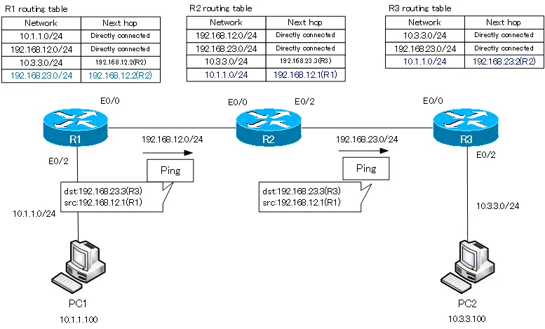
After all, we must not forget that communication is a two-way process. R3 returns an ICMP echo reply to R1 in response to a ping. The destination/source IP address is as follows
destination IP : 192.168.12.1
source IP : 192.168.23.3
Discard the IP packet destined to 192.168.12.1 because there is no route information in the routing table on R3 to forward it.
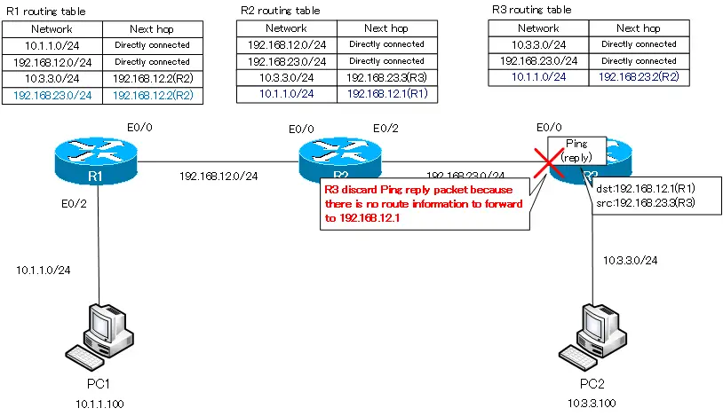
Configure static route 192.168.12.0/24 on R3
Configure R3 with a static route of 192.168.12.0/24 so that R3 can reply to pings.
R3 static route of 192.168.12.0/24
ip route 192.168.12.0 255.255.255.0 192.168.23.2
If you verify the routing table on R3, you will see the following
R3 routing table
R3#show ip route
-- ommitted --

Gateway of last resort is not set

S    192.168.12.0/24 [1/0] via 192.168.23.2
     10.0.0.0/24 is subnetted, 2 subnets
C       10.3.3.0 is directly connected, Ethernet0/2
S       10.1.1.0 [1/0] via 192.168.23.2
C    192.168.23.0/24 is directly connected, Ethernet0/0
This will finally allow pinging from R1 to R3 to succeed.
ping from R1 to R3
R1#ping 192.168.23.3

Type escape sequence to abort.
Sending 5, 100-byte ICMP Echos to 192.168.23.3, timeout is 2 seconds:
!!!!!
Success rate is 100 percent (5/5), round-trip min/avg/max = 60/67/92 ms
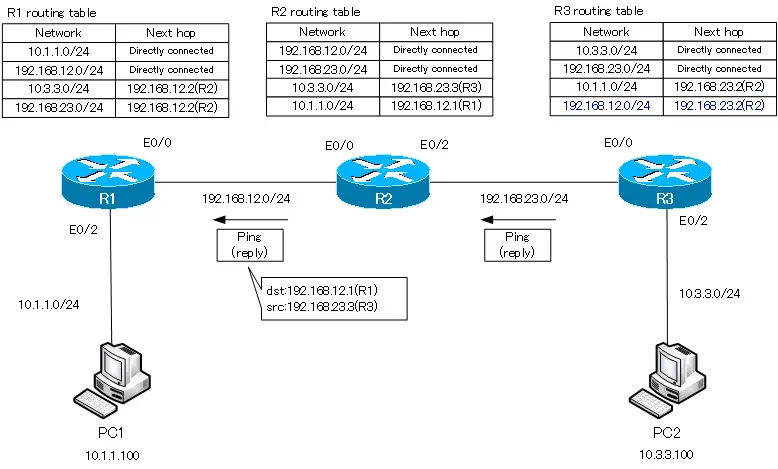
The final routing table for R1 to R3 will look like the following
R1 routing table
R1#show ip route
-- omitted --

Gateway of last resort is not set

C    192.168.12.0/24 is directly connected, Ethernet0/0
     10.0.0.0/24 is subnetted, 2 subnets
S       10.3.3.0 [1/0] via 192.168.12.2
C       10.1.1.0 is directly connected, Ethernet0/2
S    192.168.23.0/24 [1/0] via 192.168.12.2
R2 routing table
R2#show ip route
-- omitted --

Gateway of last resort is not set

C    192.168.12.0/24 is directly connected, Ethernet0/0
     10.0.0.0/24 is subnetted, 2 subnets
S       10.3.3.0 [1/0] via 192.168.23.3
S       10.1.1.0 [1/0] via 192.168.12.1
C    192.168.23.0/24 is directly connected, Ethernet0/2
R3 routing table
R3#show ip route
-- omitted --

Gateway of last resort is not set

S    192.168.12.0/24 [1/0] via 192.168.23.2
     10.0.0.0/24 is subnetted, 2 subnets
C       10.3.3.0 is directly connected, Ethernet0/2
S       10.1.1.0 [1/0] via 192.168.23.2
C    192.168.23.0/24 is directly connected, Ethernet0/0
Only when all the route information for the following four networks are registered in the routing table on R1 to R3, will communication between these four networks be possible.
- 10.1.1.0/24
- 10.3.3.0/24
- 192.168.12.0/24
- 192.168.23.0/24
When actually configuring static routes, there is of course no need to register them step by step like this. However, as the scale of the network grows and the number of routers and interconnected networks increases, you can imagine that the number of static routes to be configured will increase rapidly. Therefore, configuring the routing table with static routes is generally suitable for networks that are not very large.
This lesson is all about IP routing. We will compare and contrast static versus dynamic routing and highlight the benefits and drawbacks of each option. You will then get a chance to configure and monitor static routes on IOS routers by using the command-line interface, including special cases like default routes.
Router Operations
At this point, we know what the routing function is all about. Routers will maintain intelligence of the network topology and forward packets based on destinations, selecting the best path across that topology. That intelligence of the topology and changes in the topology are maintained statically or dynamically.
Dynamic information includes connected networks, which the router knows and is able to insert in the routing table. This is dynamic because if the directly connected interface goes down, then router will adjust and remove that destination from the routing table. Dynamic information also includes destinations learned via routing protocols. In some scenarios like stub networks or locations with a single link into the network or even Internet connectivity, static routing is also an option.
Identifying Static and Dynamic Routes
Static routes do not add overhead in the form of routing protocols, advertisements, and extra intelligence on the routers. They are fairly simple to configure and if you remain within a certain limit in terms of the number of static routes, then they are very flexible. However, they are static and so the router will not adjust to network changes, if you use static routing.
With dynamic routing protocols, then you have the overhead of advertising and learning networks, but you will adjust the network changes. How fast you adjust and how fast you converge to learning or selecting a different path, that depends on the routing protocol.
Static Routes
It is on those scenarios of stub networks like the one in the figure with a single link into the rest of the network, that static routing is a suitable answer.

For upstream traffic, leaving the stub network, a special case of static route, the default route is typically used to forward all traffic to all destinations outside of the stub network. The Internet is a perfect example of this. You do not really want to know the specifics of which destinations you want to reach. You know that all of them are outside and all of them are simply reachable through that one link.
So the default entry that says any unknown destination, send it this way through router A, in this example, is going to be enough. Every time we configure static routing, we should think about the bidirectional nature of traffic, and so as we send traffic outbound, we will receive return traffic coming in. If that is the case, then we would also need to configure static routing on router A in this case, pointing to the networks on the stub. In some instances, you could even see hybrids of static and dynamic routing. For outbound traffic, you would configure a default route at router B and for inbound traffic, you could configure B to advertise those routes with the dynamic routing protocol and then traffic coming inbound would be known to A and be forwarded by A.
In order to configure static routing in Cisco IOS routers, this is the command to use.
Router(config)#ip route [network/host] [mask] [address/interface] [distance] [permanent]
The IP route command includes the destination network followed by a mask and so you can insert CIDRE or Classless Inter-Domain Routing Entries pointing to subnets with multiple mask sizes. The ultimate entry would be a /32, a host entry in the routing table, where the destination is an actual host and not a network. The next component is the next-hop and this could take the form of an IP address that of the next router in the path or a local interface, which would be the interface to use to get to the destination network.
It is recommended that you use point-to-point interfaces when using this option. It will not work if the interface is a multi-access interface like Ethernet. Default administrative distance for static routes is one, and you can change this parameter to create floating static routes for backup connectivity. Remember, the administrative distance is the priority of the protocol. With an admin distance of 1, static routes will step on and overwrite most dynamic routing protocols. In other words, if the same destination is learned via routing protocol and you insert a static route to it, then the static route will win because it has the lower administrative distance.
Static Route Example
Here is an example of a static route configured at router A there.

RouterX(config)# ip route 172.16.1.0 255.255.255.0 172.16.2.1
Or:
RouterX(config)# ip route 172.16.1.0 255.255.255.0 s0/0/0
It points to the stub network and there are two options here, one to point to router B’s IP address on the serial interface or simply specify the local serial interface of router A. The interface option is typically used in floating static routes and backups and the IP address is typically used in a single point-to-point link scenario. Remember, this is only a unidirectional route; if you want traffic to leave the stub network, you would have to define static routing or dynamic routing also at router B.
Default Routes
And here is how to do that. This time the static route at router B points to all unknown destinations. This is designated by all zeros in the destination and mask.

RouterX(config)# ip route 0.0.0.0 0.0.0.0 172.16.2.2
Notice the three indicators of default routes: the first one is the all zeros destination, this signals the default route; secondly, the asterisk (*) is a candidate default and there could be more than one in a certain router; and finally, the indication up there that says gateway of last resort is 0.0.0.0. The entry is not only a default but a static default as designated by the S in the first column.
Router#sh ip route
Codes: C – connected, S – static, R – RIP, M – mobile, B – BGP
D – EIGRP, EX – EIGRP external, O – OSPF, IA – OSPF inter area
N1 – OSPF NSSA external type 1, N2 – OSPF NSSA external type 2
E1 – OSPF external type 1, E2 – OSPF external type 2
i – IS-IS, su – IS-IS summary, L1 – IS-IS level-1, L2 – IS-IS level-2
ia – IS-IS inter area, * – candidate default, U – per-user static route
o – ODR, P – periodic downloaded static routeGateway of last resort is 192.168.1.1 to network 0.0.0.0
C 192.168.62.0/24 is directly connected, FastEthernet0/0
C 192.168.1.0/24 is directly connected, FastEthernet0/1
S* 0.0.0.0/0 [1/0] via 192.168.1.1
Our Recommended Premium CCNA Training Resources
В прошлой шпаргалке мы выполнили базовую настройку роутера и назначили IP-адреса интерфейсам роутера («Базовая настройка роутера Cisco»).
Однако (надеюсь Вы помните из готового примера), у нас еще нет возможности отправить удачный пинг в другую сеть (из PC1 к PC3).
Для этого мы и настроим статическую маршрутизацию, которая будет объяснять роутеру где находится другая сеть.
// Так я буду обозначать комментарии.
-
Устанавливаем консольное соединение через гипертерминал со следующими настройками:
- Скорость: 9600; Биты данных: 8; Четность: Нет; Стоповые биты: 1; Управление потоком: Нет;
- //при входе на роутер вводим пароль — cisco
- R1>enable//Входим в привилегированный режим.
- //вводим пароль — class
- R1#
- R1#configure terminal//заходим в режим глобальной конфигурации
- R1(config)#ip route 172.16.0.0 255.255.255.128 Serial0/0/0//это команда для ввода статического маршрута/ Объясняю вкратце: ip route — это команда, говорящая роутеру, что сейчас будет введен статический маршрут; 172.16.0.0 — это удаленная и неизвестная роутеру сеть; 255.255.255.128 — это маска удаленной сети; serial0/0/0 — это на какой интерфейс слать пакеты, предназначающиеся для той, удаленной сети.
- //помимо вышеназванного способа можно воспользоваться другими командами:
ip route 172.16.0.0 255.255.255.128 192.168.0.194 — в этом случае все тоже самое, только вместо указания интерфейса на какой слать пакеты, указан IP-адрес подключенного интерфейса следующего роутера.
ip route 172.16.0.0 255.255.0.0 Serial0/0/0 — здесь мы увеличили диапазон адресов маской. Теперь на интерфейс уйдут не только пакеты с адресами 172.16.0.1-126, но и 172.16.255.254. Это называется суммированием маршрутов, и заслуживает другой статьи.
ip route 0.0.0.0 0.0.0.0 Serial0/0/0 — а это называется маршрут по умолчанию, т.е. всё, что не предназначается для известных роутеру сетей уйдёт на интерфейс Serial0/0/0.
- R1(config-line)#end//выходим в привилегированный режим EXEC Mode
- R1#show running-config//Проверяем введенные данные.
- R1#copy running-config startup-config//Сохраняем произведенную настройку в энерго-независимую память.
Скачать выполненное задание настройки роутера
Предлагаю скачать файл с выполненным заданием для программы эмулятора PacketTracer, открыть его и посмотреть на реализацию. Роутер R2 тоже настроен со статической маршрутизацией, следовательно теперь всё удачно пингуется.
Настройка роутера копированием конфигурации
-
Для автоматической базовой настройки (всё, что выше) маршрутизатора выполните следующие действия:
- 1. Скопируйте текст ниже в буфер обмена: выделите всё, кликните правой кнопкой по выделенному и выберите «Копировать».
- 2. При необходимости очистите роутер от всех настроек и перезагрузите его.
- 3. Войдите в режим глобальной конфигурации и вызовите меню Гипер Терминала «Правка», а в нём «Передать главному компьютеру».
- 4. Обязательно проверьте настройки с помощью команды
show running-config - 5. При необходимости включите интерфейсы командой no shutdown из режима каждого интерфейса