| Автор | Сообщение |
|---|---|
|
Заголовок сообщения: Что такое IGMP Fast Leave и RTSP ALG?
|
|
|
|
Что такое и для чего нужно IGMP Fast Leave и RTSP ALG? Цитата: Доступна новая версия прошивки (RU_1.55) для устройства DSL-2500U/BRU/D (H/W: D1, D2, D3, D4). Список изменений: Ссылка для загрузки: ftp://ftp.dlink.ru/pub/ADSL/DSL-2500U_B … 062010.zip размер: 1,9 Мб |
| Вернуться наверх | |
|
Alexander Gorelik |
Заголовок сообщения: Re: Что такое IGMP Fast Leave и RTSP ALG?
|
|
|
nickm33 писал(а): Что такое и для чего нужно IGMP Fast Leave и RTSP ALG? Цитата: Доступна новая версия прошивки (RU_1.55) для устройства DSL-2500U/BRU/D (H/W: D1, D2, D3, D4). Список изменений: Ссылка для загрузки: ftp://ftp.dlink.ru/pub/ADSL/DSL-2500U_B … 062010.zip размер: 1,9 Мб
RTSP (TCP/UDP:554) — протокол передачи мультимедийных потоков, обеспечивает удаленное управление потоками аудио/видео данных в сети Интернет. Применяется операторами для предоставления услуги видео по запросу (VoD). IGMP Fast Leave относится к функционалу IGMP Snooping и обеспечивает незамедлительную передачу запросов на отключение клиента от IGMP группы из LAN сети в WAN сеть. Другими словами, сообщения IGMP leave во внешнюю сеть передаются в приоритетном порядке. |
| Вернуться наверх |
|
|
Halk |
Заголовок сообщения:
|
|
|
Эти функции нужно где-то включать или они работают по умолчанию ? _________________ |
| Вернуться наверх |
|
|
Alexander Gorelik |
Заголовок сообщения:
|
|
|
Halk писал(а): Эти функции нужно где-то включать или они работают по умолчанию ? Они работают по умолчанию, включать не нужно. |
| Вернуться наверх |
|
|
Halk |
Заголовок сообщения:
|
|
|
всё понятно. спасибо. _________________ |
| Вернуться наверх |
|
Toggle table of contents sidebar
ALG is a feature that allows several applications to work correctly when they pass through the NAT. When an application client sends a private IP address and port in its message, ALG allocates a public IP address and port and translates them in the message. Simply put, ALG does the same thing with application messages as NAT does with the regular IP header. This translation is necessary so that the application server can send a response to a correct public IP address and port.
NAT supports ALG for FTP, TFTP, PPTP, SIP, RTSP, and DNS.
9.13.1. FTP ALG
When using NAT44, the subscriber can use the passive FTP mode to work through the NAT with ALG disabled. Otherwise, if the subscriber uses the active FTP mode, ALG needs to be enabled. In this case, ALG translates the IP address and port in the PORT message.
When using NAT64, ALG must be enabled to allow subscribers to use FTP. In this case, ALG translates the IP address and port in the following messages:
-
EPRT. In addition to address and port translation, the command itself is changed toPORT. -
EPSV. The command is changed toPASV. -
227(response toPASV). The command is changed to229(response toEPSV).
Commands
- <nat|nat64> inspection ftp enable [{control-port (1-65535)|vrf NAME}]
-
FTP ALG is disabled by default. This command enables it.
- show <nat|nat64> counters [vrf NAME] alg ftp
-
Display FTP ALG counters information.
Counter
Description
FTP translationsTranslation of internal ip:port to external ip:port and vice
versaFTP packets droppedThe number of FTP packets that were dropped
FTP session entriesThe number of the sessions established at the moment
FTP session creationsThe number of the sessions established over a whole period
of the operation
- clear <nat|nat64> counters [vrf NAME] alg ftp
-
Clear FTP ALG counters.
9.13.2. TFTP ALG
TFTP does not send IP addresses in its messages, but it is incompatible with Address-and-Port-Dependent Filtering behavior. If this mode is used, TFTP ALG must be enabled to allow users to use TFTP.
Commands
- <nat|nat64> inspection tftp enable [{control-port (1-65535)|vrf NAME}]
-
TFTP ALG is disabled by default. This command enables it.
- show <nat|nat64> counters [vrf NAME] alg tftp
-
Display TFTP ALG counters information.
Counter
Description
TFTP translationsTranslation of internal ip:port to external ip:port and vice
versaTFTP session entriesThe number of the sessions established at the moment
TFTP session creationsThe number of the sessions established over a whole period
of the operation
- clear <nat|nat64> counters [vrf NAME] alg tftp
-
Clear TFTP ALG counters.
9.13.3. PPTP ALG
For both NAT44 and NAT64, PPTP ALG must be enabled to allow subscribers to use PPTP. PPTP ALG translates IP address and port in the following messages:
-
Outgoing-Call-Request
-
Outgoing-Call-Reply
-
Call-Clear-Request
-
Call-Disconnect-Notify
-
WAN-Error-Notify
-
Set-Link-Info
Commands
- <nat|nat64> inspection pptp enable [{control-port (1-65535)|vrf NAME}]
-
PPTP ALG is disabled by default. This command enables it.
- show <nat|nat64> counters [vrf NAME] alg pptp
-
Display counters for PPTP ALG.
Counter
Description
PPTP translationsTranslation of internal ip:port to external ip:port and vice
versaPPTP packets droppedThe number of PPTP packets that were dropped
PPTP outgoing call

requests
These requests are PPTP control messages sent by the PNS
(refers to the remote client) to the PAC (refers to the server)
to indicate that an outbound call from the PAC is to be
established. See RFC 2637#section-2.7PPTP call clear requestsControl message indicates that a particular call is to be
disconnected. See RFC 2637#section-2.12 for referencePPTP outgoing call
repliesControl messages from the PAC to the PNS in response to a
received Outgoing-Call-Request message.
See RFC 2637#section-2.8 for referencePPTP call disconnect
notifiesControl message from the PAC to the PNS is issued whenever a
call is disconnected. See RFC 2637#section-2.13 for referencePPTP session entriesThe number of the sessions established at the moment
PPTP session creationsThe number of the sessions established over a whole period
of the operation
- clear <nat|nat64> counters [vrf NAME] alg pptp
-
Clear PPTP ALG counters.
9.13.4. SIP ALG
Warning
The vast majority of SIP clients support NAT-traversal techniques described in RFC 6314, so SIP ALG is not necessary for them. Furthermore, you SHOULD NOT enable SIP ALG unless you have a specific reason to do that because SIP ALG may interfere with NAT traversal techniques.
For both NAT44 and NAT64, SIP ALG translates IP address and port in the following messages:
-
REGISTER
-
INVITE
-
UPDATE
-
ACK
-
PRACK
-
BYE
Commands
- <nat|nat64> inspection sip enable [{control-port (1-65535)|vrf NAME}]
-
SIP ALG is disabled by default. This command enables it.
- show <nat|nat64> counters [vrf NAME] alg sip
-
Display SIP ALG counters information.
Counter
Description
SIP translationsTranslation of internal ip:port to external ip:port and vice
versaSIP packets droppedThe number of SIP packets that were dropped
SIP session entriesThe number of the sessions established at the moment
SIP session creationsThe number of the sessions established over a whole period
of the operation
- clear <nat|nat64> counters [vrf NAME] alg sip
-
Clear SIP ALG counters.
9.13.5. RTSP ALG
Warning
The vast majority of RTSP clients support NAT-traversal techniques described in RFC 7604 and RFC 7825, so RTSP ALG is not necessary for them. Furthermore, you SHOULD NOT enable RTSP ALG unless you have a specific reason to do that because RTSP ALG may interfere with NAT traversal techniques.
For both NAT44 and NAT64, RTSP ALG translates the IP address and port in SETUP messages.
Commands
- <nat|nat64> inspection rtsp enable [{control-port (1-65535)|vrf NAME}]
-
RTSP ALG is disabled by default. This command enables it.
- show <nat|nat64> counters [vrf NAME] alg rtsp
-
Display RTSP ALG counters information.
Counter
Description
RTSP translationsTranslation of internal ip:port to external ip:port and vice
versaRTSP packets droppedThe number of RTSP packets that were dropped
RTSP setup messagesThese messages are used to specify the transport mechanism
for the streamed media. See RFC 2326#section-10.4 for
referenceRTSP session entriesThe number of the sessions established at the moment
RTSP session creationsThe number of the sessions established over a whole period
of the operation
- clear <nat|nat64> counters [vrf NAME] alg rtsp
-
Clear RTSP ALG counters.
9.13.6. DNS ALG
When using NAT44, DNS ALG is not necessary for the correct work of DNS protocol because it does not use private IP addresses in its messages. However, when you enable DNS ALG, it tracks DNS requests sent by subscribers and immediately deletes the session when the corresponding DNS response is received. This allows to significantly reduce the number of concurrent sessions in the NAT session table.
When using NAT64, DNS ALG is necessary to process DNS requests sent by subscribers through the NAT. It translates AAAA requests into A requests and A responses into AAAA responses.
Warning
The correct network architecture for NAT64 involves using a separate DNS64 network element that processes all DNS requests from subscribers. In this case, no DNS requests pass through the NAT, and DNS ALG is not necessary.
Commands
- <nat|nat64> inspection dns enable [{control-port (1-65535)|vrf NAME}]
-
DNS ALG is disabled by default. This command enables it.
- show <nat|nat64> counters [vrf NAME] alg dns
-
Display DNS ALG counters information.
Counter
Description
DNS translationsTranslation of internal ip:port to external ip:port and vice
versaDNS reply packetsDisplay the number of the reply packets
DNS oversized packetsDNS packets consider oversized when the TC flag (1 bit)
is set in the DNS header. This flag is set in the reply packet
if the server could not put all the necessary information in
the packet because of restrictionsDNS amplification
packetsShows how many requests related to DNS amplification were
droppedDNS invalid packetsThis counter will increment when the security appliance
detects an invalid DNS packet. For example, a DNS packet with
no DNS header, the number of DNS resource records not matching
the counter in the header, etc.DNS session entriesThe number of the sessions established at the moment
DNS session creationsThe number of the sessions established over a whole period
of the operation
- clear <nat|nat64> counters [vrf NAME] alg dns
-
Clear DNS ALG counters.
9.13.7. Additional Considerations
Subscribers behind the NAT may experience issues with their VPN connections when using IPsec. It happens because IPsec uses ESP as an underlying protocol, and its payload is encrypted, so it is not possible to implement an ALG that would translate IP/TCP headers inside the ESP header.
To solve this problem, subscribers should enable NAT-traversal in their IPsec VPN clients. The vast majority of them support this functionality as described in RFC 3715 and RFC 3947.
Real Time Streaming Protocol (RTSP) is an application-level protocol for the transfer of real-time media data. Used for establishing and controlling media sessions between end points, RTSP is a control channel protocol between the media client and the media server. The typical communication is between a client and a streaming media server.
Streaming media from a private network to a public network requires translating IP addresses and port numbers over the network. NetScaler functionality includes an Application Layer Gateway (ALG) for RTSP, which can be used with Large Scale NAT (LSN) to parse the media stream and make any necessary changes to ensure that the protocol continues to work over the network.
How IP address translation is performed depends on the type and direction of the message, and the type of media supported by the client-server deployment. Messages are translated as follows:
- Outbound request—Private IP address to NetScaler owned public IP address called LSN IP address.
- Inbound response—LSN IP address to private IP address.
- Inbound request—No translation.
- Outbound response—Private IP address to LSN pool IP address.
Note
RTSP ALG is supported in a NetScaler standalone appliance, in a NetScaler high availability setup, as well as in a NetScaler cluster setup.
Limitations of RTSP ALG
The RTSP ALG does not support the following:
- Multicast RTSP sessions
- RTSP session over UDP
- Admin partitions
- RTSP Authentication
- HTTP tunneling
Configuring RTSP ALG
Configure RTSP ALG as part of the LSN configuration. For instructions on configuring LSN, see Configuring Large Scale NAT64. While configuring, make sure that you:
- Set the following parameters while adding an LSN application profile:
- IP Pooling = PAIRED
- Address and Port Mapping = ENDPOINT-INDEPENDENT
- Filtering = ENDPOINT-INDEPENDENT
- Enable RTSP ALG in the LSN group
- Create a RTSP ALG profile and bind the RTSP ALG profile to the LSN group
To enable RTSP ALG for an LSN configuration by using the CLI
At the command prompt, type:
add lsn group <groupname> -clientname <string> [-rtspalg ( ENABLED | DISABLED )]

show lsn group <groupname>
<!--NeedCopy-->
To enable RTSP ALG for an LSN configuration by using the CLI
At the command prompt, type:
add lsn rtspalgprofile <rtspalgprofilename> [-rtspIdleTimeout <positive_integer>] -rtspportrange <port[-port]> [-rtspTransportProtocol (TCP|UDP)]

show lsn rtspalgprofile <rtspalgprofilename>
<!--NeedCopy-->
Sample RTSP ALG Configuration
The following sample large scale NAT64 configuration, RTSP ALG is enabled for TCP traffic from subscriber devices in the network 2001:DB8:1002::/96.
add lsn client LSN-NAT64-CLIENT-9
Done
bind lsn client LSN-NAT64-CLIENT-9 -network6 2001:DB8:1002::/96
Done
add lsn pool LSN-NAT64-POOL-9
Done
bind lsn pool LSN-NAT64-POOL-9 203.0.113.90
Done
add lsn ip6profile LSN-NAT64-PROFILE-9 -type NAT64 -natprefix 2001:DB8:309::/96
Done
add lsn appsprofile LSN-NAT64-APPS-PROFILE-9 TCP -ippooling PAIRED –mapping ENDPOINT-INDEPENDENT -filtering ENDPOINT-INDEPENDENT
Done
add lsn rtspalgprofile RTSPALGPROFILE-9 -rtspIdleTimeout 1000 -rtspportrange 554
Done
add lsn group LSN-NAT64-GROUP-9 -clientname LSN-NAT64-CLIENT-9 -ip6profile LSN-NAT64-PROFILE-7 -rtspalg ENABLED
Done
bind lsn group LSN-NAT64-GROUP-9 -poolname LSN-NAT64-POOL-9
Done
bind lsn group LSN-NAT64-GROUP-9 -appsprofilename LSN-NAT64-APPS-PROFILE-9
Done
bind lsn group LSN-NAT64-GROUP-9  -rtspalgprofilename RTSPALGPROFILE-9
Done
<!--NeedCopy-->
Chapter 11 NAT Forwarding
Modem router’s NAT (Network Address Translation) feature makes the devices in the LAN use the same public IP address to communicate in the internet, which protects the local network by hiding IP addresses of the devices. However, it also brings about the problem that external host cannot initiatively communicate with the specified device in the local network.
The modem router can use a forwarding feature to remove the isolation of NAT and allow external internet hosts to intuitively communicate with the devices in the local network, thus enabling some special features.
TP-Link modem router includes four forwarding rules. If two or more rules are set, the priority of implementation from high to low is Virtual Servers, Port Triggering, UPNP and DMZ.
This chapter contains the following sections:
•Translate Address and Port by ALG
•Share Local Resources over the Internet by Virtual Server
•Open Ports Dynamically by Port Triggering
•Make Applications Free from Port Restriction by DMZ
•Make Xbox Online Games Run Smoothly by UPnP
1. Translate Address and Port by ALG
ALG (Application Layer Gateway) allows customized NAT (Network Address Translation) traversal filters to be plugged into the gateway to support address and port translation for certain application layer “control/data” protocols: FTP, TFTP, H323 etc. Enabling ALG is recommended.
Visit http://tplinkmodem.net, and log in with your TP-Link ID or the password you set for the router. Go to Advanced > NAT Forwarding > ALG.
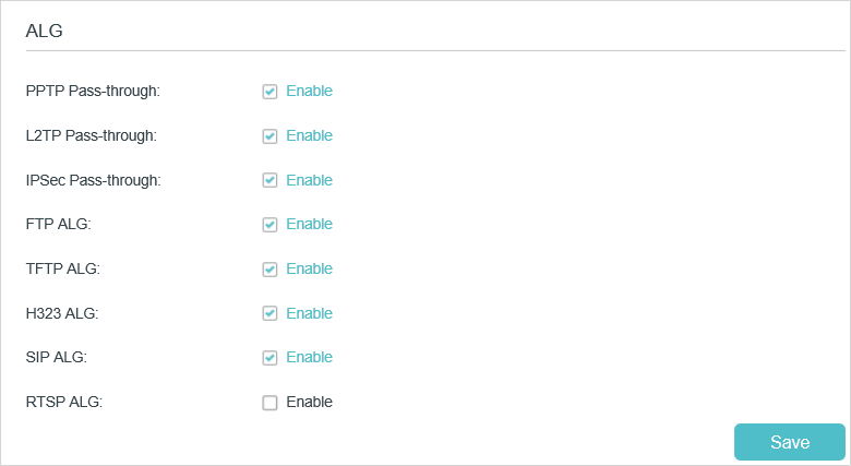
•PPTP Pass-through: If enabled, it allows Point-to-Point sessions to be tunneled through an IP network and passed through the router.
•L2TP Pass-through: If enabled, it allows Layer 2 Point-to-Point sessions to be tunneled through an IP network and passed through the router.
•IPSec Pass-through: If enabled, it allows IPSec (Internet Protocol Security) to be tunneled through an IP network and passed through the router. IPSec uses cryptographic security services to ensure private and secure communications over IP networks.
•FTP ALG: If enabled, it allows FTP (File Transfer Protocol) clients and servers to transfer data via NAT.
•TFTP ALG: If enabled, it allows TFTP (Trivial File Transfer Protocol) clients and servers to transfer data via NAT.
•H323 ALG: If enabled, it allows Microsoft NetMeeting clients to communicate via NAT.
•SIP ALG: If enabled, it allows clients communicate with SIP (Session Initiation Protocol) servers via NAT.
•RTSP ALG: If enabled, it allows RTSP (Real-Time Stream Protocol) clients and servers to transfer data via NAT.
2. Share Local Resources over the Internet by Virtual Server
When you build up a server in the local network and want to share it on the internet, Virtual Server can realize the service and provide it to the internet users. At the same time virtual server can keep the local network safe as other services are still invisible from the internet.
Virtual server can be used for setting up public services in your local network, such as HTTP, FTP, DNS, POP3/SMTP and Telnet. Different service uses different service port. Port 80 is used in HTTP service, port 21 in FTP service, port 25 in SMTP service and port 110 in POP3 service. Please verify the service port number before the configuration.
I want to:
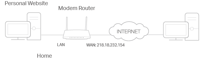
Share my personal website I’ve built in a local network with my friends through the internet.
For example, the personal website has been built on my home PC (192.168.1.100). I hope that my friends can visit my website. The PC is connected to the modem router with the WAN IP address 218.18.232.154.
How can I do that?
1.Assign a static IP address to your PC, for example 192.168.1.100.
2.Visit http://tplinkmodem.net, and log in with your TP-Link ID or the password you set for the router.
3.Go to Advanced > NAT Forwarding > Virtual Servers, click Add.
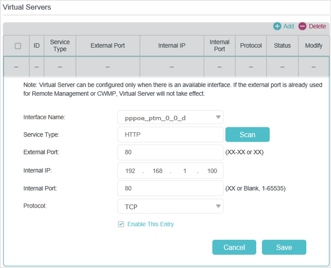
4.Click Scan, and choose HTTP. The external port, internal port and protocol will be automatically filled with contents. Enter the PC’s IP address 192.168.1.100 in the Internal IP field.
5.Click OK to save the settings.
Tips:
1.It is recommended to keep the default settings of Internal Port and Protocol if you are not clear about which port and protocol to use.
2.If the service you want to use is not in the Service Type, you can enter the corresponding parameters manually. You should verify the port number that the service needs.
3.You can add multiple virtual server rules if you want to provide several services from a modem router. Please note that the External Port cannot be overlapped.
Done!
Internet users can enter http://WAN IP (in this example: http://218.18.232.154) to visit your personal website.
Tips:
1.For a WAN IP that is assigned dynamically by ISP, it is recommended to apply and register a domain name for the WAN by DDNS, go to Set Up a Dynamic DNS Service Account for more information. Then you can use http://domain name to visit the website.
2.If you have changed the default External Port, you should use http://WAN IP: External Port or http://domain name: External Port to visit the website.
3. Open Ports Dynamically by Port Triggering
Port triggering can specify a triggering port and its corresponding external ports. When a host in the local network initiates a connection to the triggering port, all the external ports will be opened for subsequent connections. The modem router can record the IP address of the host. When the data from the internet returns to the external ports, the modem router can forward them to the corresponding host. Port triggering is mainly applied to online games, VoIPs and video players. Common applications include MSN Gaming Zone, Dialpad, Quick Time 4 players, and so on.
Follow the steps below to configure the port triggering rules:
1.Visit http://tplinkmodem.net, and log in with your TP-Link ID or the password you set for the router.
2.Go to Advanced > NAT Forwarding > Port Triggering and click Add.
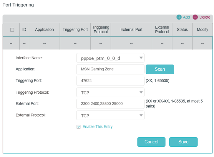
3.Click Scan, and select the desired application. The triggering port and protocol, the external port and protocol will be automatically filled with contents. Here we take MSN Gaming Zone as an example.
4.Click OK to save the settings.
Tips:
1.You can add multiple port triggering rules according to your network need.
2.If the application you need is not listed in the Existing Applications list, please enter the parameters manually. You should verify the external ports the application uses first and enter them into External Port field according to the format the page displays.
4. Make Applications Free from Port Restriction by DMZ
When a PC is set to be a DMZ (Demilitarized Zone) host in the local network, it is totally exposed to the internet, which can realize the unlimited bidirectional communication between internal hosts and external hosts. The DMZ host becomes a virtual server with all ports opened. When you are not clear about which ports to open in some special applications, like IP camera and database software, you can set the PC to be a DMZ host.
Note:
DMZ is most applicable when you don’t know which ports to open. When it is enabled, the DMZ host is totally exposed to the internet, which may bring some potential safety hazard. If DMZ is not in use, please disable it in time.
I want to:
Make the home PC join the internet online game without port restriction.
For example, Due to some port restriction, when playing the online games, you can login normally but cannot join a team with other players. To solve this problem, set your PC as a DMZ with all ports opened.
How can I do that?
1.Assign a static IP address to your PC, for example 192.168.1.100.
2.Visit http://tplinkmodem.net, and log in with your TP-Link ID or the password you set for the router.
3.Go to Advanced > NAT Forwarding > DMZ and select the checkbox to enable DMZ.
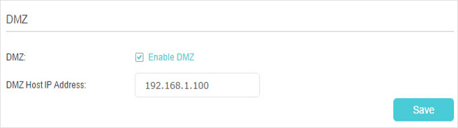
4.Enter the IP address 192.168.1.100 in the DMZ Host IP Address filed.
5.Click Save to save the settings.
Done!
The configuration is completed. You’ve set your PC to a DMZ host and now you can make a team to game with other players.
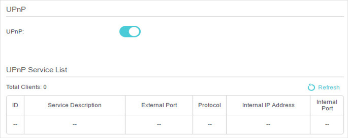
5. Make Xbox Online Games Run Smoothly by UPnP
UPnP (Universal Plug and Play) protocol allows the applications or host devices to automatically find the front-end NAT device and send request to it to open the corresponding ports. With UPnP enabled, the applications or host devices in the both sides of NAT device can freely communicate with each other realizing the seamless connection of the network. You may need to enable the UPnP if you want to use applications such as multiplayer gaming, peer-to-peer connections, real-time communication (for example, VoIP or telephone conference), or remote assistance.
Tips:
1.UPnP is enabled by default in this modem router.
2.Only the application supporting UPnP protocol can use this feature.
3.UPnP feature needs the support of operating system (e.g. Windows Vista/ Windows 7/ Windows 8, etc. Some of operating system need to install the UPnP components).
For example, when you connect your Xbox to the modem router which has connected to the internet to play online games, UPnP will send request to the modem router to open the corresponding ports allowing the following data penetrating the NAT to transmit. Therefore, you can play Xbox online games without a hitch.

If necessary, you can follow the steps to change the status of UPnP.
1.Visit http://tplinkmodem.net, and log in with your TP-Link ID or the password you set for the router.
2.Go to Advanced > NAT Forwarding > UPnP and toggle on or off according to your needs.
Overview: Using the FTP ALG Profile to Transfer Files
The File Transfer Protocol (FTP) application layer gateway (ALG) profile enables you to
transfer files between a client and server. The FTP ALG profile supports both active and
passive modes, where data connections are initiated either from an FTP server (active mode) or
from a client (passive mode). You can transfer files using the FTP protocol by configuring an
LSN pool, configuring an FTP profile, and then assigning the LSN pool and FTP profile to a
virtual server. The FTP protocol is described in RFC 959.
Task summary
About the FTP profile
The File Transfer Protocol (FTP) profile enables you to transfer
files between a client and server, using FTP connections over TCP. The FTP application layer
gateway (ALG) supports the FTP protocol’s active and passive modes, where data connections are
initiated either from an FTP server (active mode) or from a client (passive mode).
You can configure the FTP profile settings, as needed, to ensure compatibility between IPv4 and
IPv6 clients and servers, to enable the FTP data channel to inherit the TCP profile used by the
FTP control channel, and to use a port other than the default port (20).
Additionally, when used with Application Security Manager™ (ASM™), this profile enables the BIG-IP® system to inspect FTP traffic
for security vulnerabilities by using an FTP security profile.
FTP Control Channels
Once established, the FTP control channel remains open throughout the FTP session. The FTP
control channel and the FTP data channel must both originate from the same IP address.
FTP Data Channels
In active mode, the FTP server initiates data connections. A client informs the
server as to what port the client is listening on, and the server connects to the client by
using that port.
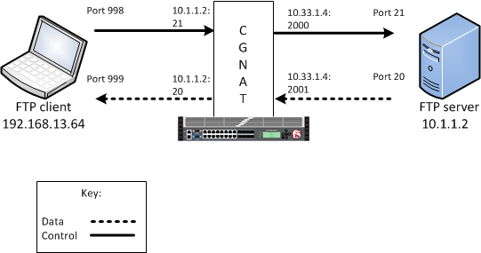
An example FTP active mode configuration
In this example, an LSN pool is configured with a translation IP address and prefix length of
10.33.1.0/24. The virtual server is configured with an FTP control port
using a wildcard address and a specific port: 0.0.0.0:21. The FTP data
port is configured to use port 20. The configured translation mode uses
the values of the respective port range.
| Translation mode | Port range |
|---|---|
| NAPT | 2000-3000 |
| DNAT | 2000-2200 |
| PBA | 2000-2150 |
In passive mode, the FTP client initiates data connections. The FTP server
informs the client as to what port the server is listening on, and the client connects to the
server by using that port.
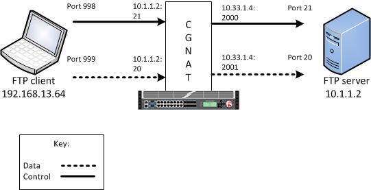
An example FTP passive mode configuration
In this example, an LSN pool is configured with a translation IP address and prefix length of
10.33.1.0/24. The virtual server is configured with an FTP control port
using a wildcard address and a specific port: 0.0.0.0:21. The FTP data
port is configured to use port 20. In this example, the configured
translation mode uses the values of the respective port range.
| Translation mode | Port range |
|---|---|
| NAPT | 2000-3000 |
| DNAT | 2000-2200 |
| PBA | 2000-2150 |
Creating an LSN pool
The carrier-grade NAT (CGNAT) module must be enabled with the appropriate settings before you can create large-scale NAT (LSN) pools.
LSN pools are used by the CGNAT module to allow efficient configuration of translation prefixes and parameters.
-
On the Main tab, click .
The LSN Pool List screen opens.
-
Click Create.
-
In the Name field, type a unique name.
-
In the Configuration area, for the Persistence Mode
setting, select Address or Address
Port. -
For the Member List setting, type an address and a
prefix length in the Address/Prefix Length field, and
click Add.If your pool uses deterministic mode, ensure that any address ranges you enter
as a member do not overlap another member’s prefix address ranges. For example,
the address and prefix 10.10.10.0/24 overlaps
10.10.10.0/23. -
Click Finished.
Creating an FTP profile
You can configure a file transfer protocol (FTP) profile on the BIG-IP® system that transfers files, either in an active or passive mode, and
logs related messages.
-
On the Main tab, click .
The FTP screen opens and displays a list of available FTP ALG
profiles. -
Click Create.
-
Type a name for the profile.
-
From the Parent Profile list, select a parent
profile. -
Select the Custom check box.
-
Select the Translate Extended check box to ensure
compatibility between IPv4 and IPv6 clients and servers when using the FTP
protocol. The default is selected. -
Select the Inherit Parent Profile check box to enable
the FTP data channel to inherit the TCP profile used by the control channel. The
check box is clear by default.Note: If disabled,
the data channel uses FastL4 (BigProto) only. -
In the Data Port field, type a number for an alternate
port. The default value for the FTP data port is 20.
-
Click Finished.
An FTP profile is configured on the BIG-IP® system that transfers files, either in an active or passive mode, and
logs related messages.
Configuring a CGNAT iRule
You create iRules® to automate traffic forwarding for XML
content-based routing. When a match occurs, an iRule event is triggered, and the iRule
directs the individual request to an LSN pool, a node, or virtual server.
-
On the Main tab, click .
The iRule List screen opens.
-
Click Create.
-
In the Name field, type a 1 to 31 character name, such
as cgn_https_redirect_iRule. -
In the Definition field, type the syntax for the iRule
using Tool Command Language (Tcl) syntax.For complete and detailed information about iRules syntax, see the F5 Networks
DevCentral web site (http://devcentral.f5.com). -
Click Finished.
You now have an iRule to use with a CGNAT virtual server.
Creating a virtual server using an FTP ALG profile
Virtual servers are matched based on source (client) addresses. Define a virtual
server in order to reference an FTP profile and LSN pool.
-
On the Main tab, click .
The Virtual Server List screen opens.
-
Click the Create button.
The New Virtual Server screen opens.
-
In the Name field, type a unique name for the virtual
server. -
From the Type list, retain the default setting
Standard. -
In the Destination Address field, type the IP address in
CIDR format.The supported format is address/prefix, where the prefix length is in bits.
For example, an IPv4 address/prefix is 10.0.0.1 or
10.0.0.0/24, and an IPv6 address/prefix is
ffe1::0020/64 or
2001:ed8:77b5:2:10:10:100:42/64. When you use an IPv4
address without specifying a prefix, the BIG-IP® system
automatically uses a /32 prefix.Note: The IP
address you type must be available and not in the loopback
network. -
In the Service Port field, type
21 or select FTP from the
list. -
From the Protocol list, select
TCP. -
From the Protocol Profile (Client) list, select a
predefined or user-defined TCP profile. -
From the Protocol Profile (Server) list, select a
predefined or user-defined TCP profile. -
From the FTP Profile list, select an FTP ALG profile for
the virtual server to use. -
For the LSN Pool setting, select the pool that this
server will draw on for addresses. -
Locate the Resources area of the screen; for the Related
iRules setting, from the Available list,
select the name of the iRule that you want to assign and move the name to the
Enabled list.This setting applies to virtual servers that reference a profile for a data
channel protocol, such as FTP or RTSP. -
Click Finished.
The custom CGNAT virtual server appears in the CGNAT Virtual Servers list.
Creating an FTP ALG logging profile
You can create an application layer gateway (ALG) logging profile, and associate it
with one or more FTP ALG profiles, to allow you to configure logging options for various
events that apply to high-speed logging (HSL) destinations. A logging profile decreases
the need to maintain a number of customized profiles where the events are very
similar.
-
On the Main tab, click .
The ALG logging profiles screen opens.
-
Click Create.
The New ALG Logging Profile screen opens.
-
In the Name field, type a unique name for the logging
profile. -
From the Parent Profile list, select a profile from
which the new profile inherits properties. -
For the Log Settings area, select the Custom check box.
-
For the Log Settings area, select Enabled for the
following settings, as necessary.Setting Description
Start Control Channel
Generates event log entries at the start of a control channel
connection for an ALG client.
End Control Channel
Generates event log entries at the end of a control channel
connection for an ALG client.
Start Data Channel
Generates event log entries at the start of a data channel
connection for an ALG client.
End Data Channel
Generates event log entries at the end of a data channel connection
for an ALG client.
Inbound Transaction
Generates event log entries of ALG messages triggered by an inbound
connection to the BIG-IP® system. -
Click Finished.
Configuring an FTP ALG profile
You can associate an FTP ALG profile with a log publisher and logging profile that
the BIG-IP® system uses to send log messages to a specified
destination.
-
On the Main tab, click .
The FTP screen opens and displays a list of available FTP ALG
profiles. -
Click the name of an FTP profile.
-
From the Logging Profile list, select the logging
profile the BIG-IP system uses to configure logging options for various ALG
events.Note: If you
configure a Logging Profile, you must also configure a Log Publisher. -
Click Finished.
Overview: Using the SIP ALG Profile for Multimedia Sessions
The Session Initiation Protocol (SIP) application layer gateway (ALG) profile enables you to
manage peer-to-peer connections through a CGNAT, permitting a client on an external network to
initiate and establish a multimedia session with a user on an internal network. You can enable
SIP multimedia sessions by configuring an LSN pool, configuring a SIP profile, and then
assigning the LSN pool and SIP profile to a virtual server. The SIP protocol is described in
RFC 3261.
Task summary
About the SIP ALG profile
The Session Initiation Protocol (SIP) profile establishes connections
over TCP, UDP, and SCTP through a CGNAT. It creates the connections by establishing flows for
multimedia traffic, and by translating IP addresses included in SIP messages into external IP
addresses. As a result, these can be reached by means of a public network. Once a call is
established, the SIP ALG creates flows for multimedia traffic (as determined by the advertised
address and port combinations on either side of a call), and tears down the flow when the call
ends.
You can configure the SIP profile settings, as needed, to provide the following
functionality.
- A maximum message size
- Closed connection when a BYE transaction completes
- Use of SIP dialog information
- High-speed logging (HSL) security checking
- Association of a SIP virtual server-profile pairing with a SIP proxy functional group
- Via headers
- Record-Route headers
- Real-Time Transport (RTP) proxy style for media relaying
- Timing for dialog establishment or SIP session tunnel
- Definition of maximum media sessions, sessions per registration, or registrations
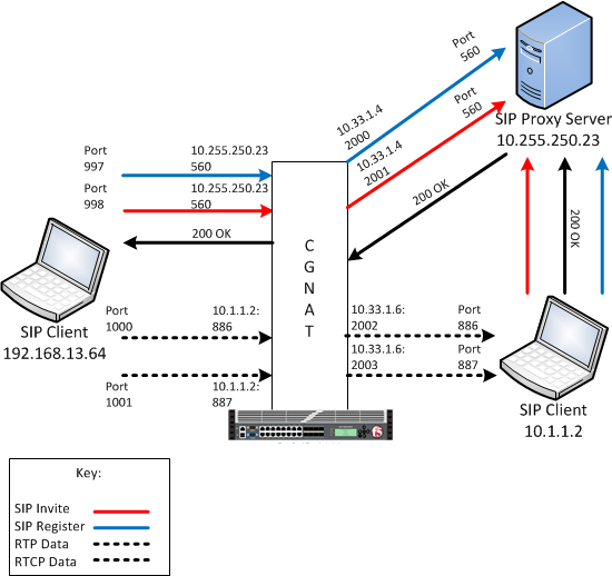
An example SIP ALG configuration
In this example, an LSN pool is configured with a translation IP address and prefix length of
10.33.1.0/24. The virtual server is configured with a register and invite
port that use a wildcard destination address and a specific port:
0.0.0.0:560. The SIP RTP data port is configured to use port
886 and the RTCP data port is configured to use port
887. The configured translation mode uses the values of the respective
port range.
| Translation mode | Port range |
|---|---|
| NAPT | 2000-3000 |
| DNAT | 2000-2200 |
| PBA | 2000-2150 |
Creating an LSN pool
The carrier-grade NAT (CGNAT) module must be enabled with the appropriate settings before you can create large-scale NAT (LSN) pools.
LSN pools are used by the CGNAT module to allow efficient configuration of translation prefixes and parameters.
-
On the Main tab, click .
The LSN Pool List screen opens.
-
Click Create.
-
In the Name field, type a unique name.
-
In the Configuration area, for the Persistence Mode
setting, select Address or Address
Port. -
For the Member List setting, type an address and a
prefix length in the Address/Prefix Length field, and
click Add.If your pool uses deterministic mode, ensure that any address ranges you enter
as a member do not overlap another member’s prefix address ranges. For example,
the address and prefix 10.10.10.0/24 overlaps
10.10.10.0/23. -
Click Finished.
Creating a SIP profile
You can configure a session initiation protocol (SIP) profile on the BIG-IP® system that manages peer-to-peer connections through a CGNAT.
-
On the Main tab, click .
The SIP screen opens and displays a list of available SIP ALG
profiles. -
Click Create.
-
Type a name for the profile.
-
From the Parent Profile list, select a parent
profile. -
Select the Custom check box.
-
In the Maximum Size (Bytes) field, type a number to
specify the maximum size, in bytes, for a SIP message. The default is
65535 bytes. -
Clear the Terminate on BYE check box.
Important: You must
clear the Terminate on BYE check box for a TCP or UDP
connection when the BIG-IP system functions as a SIP proxy, configuring the
inbound SNAT and consolidating multiple calls into one server-side
connection. You should select the Terminate on BYE
check box to improve performance only for a UDP connection if each client
call comes from a unique IP address and no inbound SNATs are
configured. -
Select the Dialog Aware check box to gather SIP dialog
information, and automatically forward SIP messages belonging to the known SIP
dialog. The default is cleared. -
Select the Security check box to enable the use of
enhanced HSL security checking. The default is cleared. -
With the Dialog Aware check box selected, in the
Community field, type a string to indicate whether
the SIP virtual server-profile pair belongs to the same SIP proxy functional
group. -
Configure the Insert Via Header settings.
-
From the Insert Via Header list, select
Enabled to insert a Via header in the
forwarded SIP request. The default is
Disabled. -
With the Insert Via Header setting enabled, in
the User Via field type a value that the system
inserts as the top Via header in a SIP REQUEST
message.
-
-
Select the Secure Via Header check box to insert a
secure Via header in the forwarded SIP request. The default is cleared. -
Select the Insert Record-Route Header check box to
insert a Record-Route SIP header, which indicates the next hop for the following
SIP request messages. The default is cleared. -
Configure the Application Level Gateway settings.
-
From the Application Level Gateway list, select
Enabled to provide options for defining ALG
settings. The default is Disabled. -
From the RTP Proxy Style list, select
Symmetric. -
In the Dialog Establishment Timeout field, type
an interval, in seconds, during which the system attempts to establish a
peer-to-peer SIP relationship between two user agents, which facilitates
sequencing of messages and proper routing of requests between two user
agents. The default is 10. -
In the Registration Timeout field, type a time,
in seconds, that elapses before the SIP registration process expires.
The default is 3600.Note: When configuring a SIP profile for use with Port Block Allocation (PBA), the
Registration Timeout value must be less
than the PBA Block Lifetime value. -
In the SIP Session Timeout field, type an idle
time, in seconds, after which the SIP session times out. The default is
300. -
In the Maximum Media Sessions field, type a
maximum number of allowable sessions. The default is
6. -
In the Maximum Sessions Per Registration field,
type a maximum number of allowable sessions per registration. The
default is 50. -
In the Maximum Registrations field, type a
maximum number of allowable registrations. The default is
100.
-
-
Select the SIP Firewall check box to indicate that SIP
firewall capability is enabled. The default is cleared. -
Click Finished.
A SIP profile is configured on the BIG-IP® system that manages peer-to-peer connections through a CGNAT.
Creating a virtual server using a SIP ALG profile
Virtual servers are matched based on source (client) addresses. Here are the steps
to define a virtual server that references a SIP profile and LSN pool.
-
On the Main tab, click .
The Virtual Server List screen opens.
-
Click the Create button.
The New Virtual Server screen opens.
-
In the Name field, type a unique name for the virtual
server. -
From the Type list, retain the default setting
Standard. -
For a network, in the Destination Address field, type an
IPv4 or IPv6 address in CIDR format to allow all traffic to be translated.The supported format is address/prefix, where the prefix length is in bits.
For example, an IPv4 address/prefix is 0.0.0.0/0, and an
IPv6 address/prefix is ::/0. -
In the Service Port field, type
5060. -
From the Configuration list, select
Advanced. -
From the Protocol list, select one of the
following:-
UDP
-
TCP
-
*All Protocols
-
-
From the Protocol Profile (Client) list, select a
predefined or user-defined profile. -
From the Protocol Profile (Server) list, select a
predefined or user-defined profile. -
From the SIP Profile list, select a SIP ALG profile for
the virtual server to use. -
For the LSN Pool setting, select the LSN pool that this
server uses for addresses. -
From the Source Port list, select
Change. -
Click Finished.
The custom CGNAT virtual server appears in the CGNAT Virtual Servers list.
Creating an empty LSN pool
The CGNAT module must be enabled through the screen before you can create LSN pools.
Large Scale NAT (LSN) pools are used by the CGNAT module to allow efficient
configuration of translation prefixes and parameters.
-
On the Main tab, click .
The LSN Pool List screen opens.
-
Click Create.
-
In the Name field, type a unique name.
-
From Persistence Mode, select to persist on
Address Port.This is the address mode the CGNAT module uses to track and store connection
data. -
From the Log Publisher list, select the log publisher
the BIG-IP system uses to send log messages to a specified destination.Important: If you
configure a log publisher to use multiple logging destinations, then, by
default, all logging destinations must be available in order to log to each
destination. Unless all logging destinations are available, no logging can
occur. If you want to log to the available logging destinations when one or
more destinations become unavailable, you must set the
logpublisher.atomic db variable to false. -
Click Finished.
Your empty LSN pool is now ready.
Creating a virtual server using a SIP ALG profile and empty LSN pool
Virtual servers are matched based on source (client) addresses. Here are the steps
to define a virtual server that references a SIP profile and LSN pool.
-
On the Main tab, click .
The Virtual Server List screen opens.
-
Click the Create button.
The New Virtual Server screen opens.
-
In the Name field, type a unique name for the virtual
server. -
From the Type list, retain the default setting
Standard. -
In the Source field, type
0.0.0.0/0. -
For a host, in the Destination Address field, type an
IPv4 or IPv6 address in CIDR format to allow all traffic to be translated.The supported format is address/prefix, where the prefix length is in bits.
For example, an IPv4 address/prefix is 0.0.0.0/0, and an
IPv6 address/prefix is ::/0. -
In the Service Port field, type the port number
5060 for the service. -
From the Configuration list, select
Advanced. -
From the Protocol list, select one of the
following:-
UDP
-
TCP
-
*All Protocols
-
-
From the Protocol Profile (Client) list, select a
predefined or user-defined profile. -
From the Protocol Profile (Server) list, select a
predefined or user-defined profile. -
From the SIP Profile list, select the same SIP ALG
profile for this virtual server to use as the other virtual server. -
For the LSN Pool setting, select the empty pool that
this server will use for addresses. -
Click Finished.
The custom CGNAT virtual server appears in the CGNAT Virtual Servers list.
Creating an SIP ALG logging profile
You can create an ALG logging profile, and associate it with one or more SIP ALG profiles, to allow you to configure logging
options for various events that apply to high-speed logging (HSL) destinations. A logging profile decreases the need to maintain a number of
customized profiles where the events are very similar.
-
On the Main tab, click .
The ALG logging profiles screen opens.
-
Click Create.
The New ALG Logging Profile screen opens.
-
In the Name field, type a unique name for the logging
profile. -
From the Parent Profile list, select a profile from
which the new profile inherits properties. -
For the Log Settings area, select the Custom check box.
-
For the Log Settings area, select Enabled for the
following settings, as necessary.Setting Description
Start Control Channel
Generates event log entries at the start of a control channel
connection for an ALG client.
End Control Channel
Generates event log entries at the end of a control channel
connection for an ALG client.
Start Data Channel
Generates event log entries at the start of a data channel
connection for an ALG client.
End Data Channel
Generates event log entries at the end of a data channel connection
for an ALG client.
Inbound Transaction
Generates event log entries of ALG messages triggered by an inbound
connection to the BIG-IP® system. -
Click Finished.
Configuring an SIP ALG profile
You can associate an SIP ALG profile with a log publisher and logging profile that
the BIG-IP® system uses to send log messages to a specified
destination.
-
On the Main tab, click .
The SIP screen opens and displays a list of available SIP ALG
profiles. -
Click the name of an SIP profile.
-
From the Logging Profile list, select the logging
profile the BIG-IP system uses to configure logging options for various ALG
events.Note: If you
configure a Logging Profile, you must also configure a Log Publisher. -
Click Finished.
Overview: Using the RTSP ALG Profile to Stream Media
The Real Time Streaming Protocol (RTSP) application layer gateway (ALG) profile enables you to
establish streaming multimedia sessions between a client and a server. You can stream
multimedia sessions by configuring an LSN pool, configuring an RTSP profile, and then
assigning the LSN pool and RTSP profile to a virtual server. The RTSP protocol is described in
RFC 2326.
Task summary
About the RTSP ALG profile
The Real Time Streaming Protocol (RTSP) profile enables you to stream multimedia
content between a client and server, using RTSP connections over TCP. The RTSP application layer
group (ALG) supports the RTSP protocol’s control channel to an RTSP server, through which the
client requests a file for the server to stream (and controls the streaming of that file with
commands like play or pause). The client can request streaming over UDP and provide two listening
ports for the server response. The RTSP server responds with a Real-Time Transport Protocol (RTP)
data channel port, to stream the requested file, and a Real-Time Control Protocol (RTCP) control
channel port, which provides a stream description and status.
Note: You can specify RTP and RTCP port numbers in the RTSP profile, which only apply
when a client connects to a Windows Media server. If you configure RTP and RTCP port numbers,
both values must be nonzero.
You can configure the RTSP profile settings, as needed.
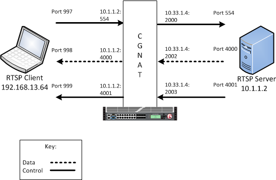
An example RTSP ALG configuration
In this example, an LSN pool is configured with a translation IP address and prefix length of
10.33.1.0/24. The virtual server is configured with an RTSP control port
using a wildcard address and a specific port: 0.0.0.0:554. The configured
translation mode uses the values of the respective port range.
| Translation mode | Port range |
|---|---|
| NAPT | 2000-3000 |
| DNAT | 2000-2200 |
| PBA | 2000-2150 |
Creating an LSN pool
The carrier-grade NAT (CGNAT) module must be enabled with the appropriate settings before you can create large-scale NAT (LSN) pools.
LSN pools are used by the CGNAT module to allow efficient configuration of translation prefixes and parameters.
-
On the Main tab, click .
The LSN Pool List screen opens.
-
Click Create.
-
In the Name field, type a unique name.
-
In the Configuration area, for the Persistence Mode
setting, select Address or Address
Port. -
For the Member List setting, type an address and a
prefix length in the Address/Prefix Length field, and
click Add.If your pool uses deterministic mode, ensure that any address ranges you enter
as a member do not overlap another member’s prefix address ranges. For example,
the address and prefix 10.10.10.0/24 overlaps
10.10.10.0/23. -
Click Finished.
Creating an RTSP profile
You can configure a real time streaming protocol (RTSP) profile on the BIG-IP® system that streams multimedia content between a client and
server.
-
On the Main tab, click .
The RTSP screen opens and displays a list of available RTSP ALG
profiles. -
Click Create.
-
Type a name for the profile.
-
From the Parent Profile list, select a parent
profile. -
Select the Custom check box.
-
In the RTP Port field, type the port number that a
Microsoft Media Services server uses. The default is
0.Note: You can specify
Real-Time Transport Protocol (RTP) and Real-Time Control Protocol (RTCP)
port numbers in the RTSP profile, which only apply when a client connects to
a Windows
Media® server. If you configure RTP and RTCP port numbers, both
values must be nonzero. -
In the RTCP Port field, type the port number that a
Microsoft Media Services server uses. The default is
0.Note: You can specify
Real-Time Transport Protocol (RTP) and Real-Time Control Protocol (RTCP)
port numbers in the RTSP profile, which only apply when a client connects to
a Windows
Media® server. If you configure RTP and RTCP port numbers, both
values must be nonzero. -
Click Finished.
An RTSP profile is configured on the BIG-IP® system that
streams multimedia content between a client and server.
Configuring a CGNAT iRule
You create iRules® to automate traffic forwarding for XML
content-based routing. When a match occurs, an iRule event is triggered, and the iRule
directs the individual request to an LSN pool, a node, or virtual server.
-
On the Main tab, click .
The iRule List screen opens.
-
Click Create.
-
In the Name field, type a 1 to 31 character name, such
as cgn_https_redirect_iRule. -
In the Definition field, type the syntax for the iRule
using Tool Command Language (Tcl) syntax.For complete and detailed information about iRules syntax, see the F5 Networks
DevCentral web site (http://devcentral.f5.com). -
Click Finished.
You now have an iRule to use with a CGNAT virtual server.
Creating a virtual server using an RTSP ALG profile
Virtual servers are matched based on source (client) addresses. Here are the steps
to define a virtual server that references an RTSP profile and LSN pool.
-
On the Main tab, click .
The Virtual Server List screen opens.
-
Click the Create button.
The New Virtual Server screen opens.
-
In the Name field, type a unique name for the virtual
server. -
From the Type list, retain the default setting
Standard. -
In the Destination Address field, type the IP address in
CIDR format.The supported format is address/prefix, where the prefix length is in bits.
For example, an IPv4 address/prefix is 10.0.0.1 or
10.0.0.0/24, and an IPv6 address/prefix is
ffe1::0020/64 or
2001:ed8:77b5:2:10:10:100:42/64. When you use an IPv4
address without specifying a prefix, the BIG-IP® system
automatically uses a /32 prefix.Note: The IP
address you type must be available and not in the loopback
network. -
In the Service Port field, type
554 for the service. -
From the Protocol list, select
TCP. -
From the Protocol Profile (Client) list, select a
predefined or user-defined TCP profile. -
From the Protocol Profile (Server) list, select a
predefined or user-defined TCP profile. -
From the RTSP Profile list, select an RISP ALG profile
for the virtual server to use. -
For the LSN Pool setting, select the pool that this
server will draw on for addresses. -
Locate the Resources area of the screen; for the Related
iRules setting, from the Available list,
select the name of the iRule that you want to assign and move the name to the
Enabled list.This setting applies to virtual servers that reference a profile for a data
channel protocol, such as FTP or RTSP. -
Click Finished.
The custom CGNAT virtual server appears in the CGNAT Virtual Servers list.
Creating an RTSP ALG logging profile
You can create an ALG logging profile, and associate it with one or more RTSP ALG profiles,
to allow you to configure logging options for various events that apply to high-speed logging (HSL) destinations. A logging profile decreases the need to maintain a number of customized profiles where the events are very similar.
-
On the Main tab, click .
The ALG logging profiles screen opens.
-
Click Create.
The New ALG Logging Profile screen opens.
-
In the Name field, type a unique name for the logging
profile. -
From the Parent Profile list, select a profile from
which the new profile inherits properties. -
For the Log Settings area, select the Custom check box.
-
For the Log Settings area, select Enabled for the
following settings, as necessary.Setting Description
Start Control Channel
Generates event log entries at the start of a control channel
connection for an ALG client.
End Control Channel
Generates event log entries at the end of a control channel
connection for an ALG client.
Start Data Channel
Generates event log entries at the start of a data channel
connection for an ALG client.
End Data Channel
Generates event log entries at the end of a data channel connection
for an ALG client.
Inbound Transaction
Generates event log entries of ALG messages triggered by an inbound
connection to the BIG-IP® system. -
Click Finished.
Configuring an RTSP ALG profile
You can associate an RTSP ALG profile with a log publisher and logging profile that
the BIG-IP® system uses to send log messages to a specified
destination.
-
On the Main tab, click .
The RTSP screen opens and displays a list of available RTSP ALG
profiles. -
Click the name of an RTSP profile.
-
From the Logging Profile list, select the logging
profile the BIG-IP system uses to configure logging options for various ALG
events.Note: If you
configure a Logging Profile, you must also configure a Log Publisher. -
Click Finished.
Overview: Using the PPTP ALG profile to create a VPN tunnel
The point-to-point tunneling protocol (PPTP) profile enables you to configure the BIG-IP® system to support a secure virtual private network (VPN) tunnel
that forwards PPTP control and data connections. You can create a secure VPN tunnel by
configuring a PPTP Profile, and then assigning the PPTP profile to a virtual server. The PPTP
protocol is described in RFC 2637.
Important: You cannot combine or use the PPTP
Profile with another profile other than a TCP Profile. The PPTP Profile must be used
separately and independently.
Task summary
About the PPTP ALG profile
The point-to-point tunneling protocol (PPTP) profile enables you to configure the
BIG-IP® system to support a secure virtual private network (VPN)
tunnel. A PPTP application layer gateway (ALG) forwards PPTP client (also known as PPTP Access
Concentrator [PAC]) control and data connections through the BIG-IP system to PPTP servers
(also known as PPTP Network Servers [PNSs]), while providing source address translation that
allows multiple clients to share a single translation address.
The PPTP profile defines a Transmission Control Protocol (TCP) control connection and a data
channel through a PPTP Generic Routing Encapsulation (GRE) tunnel, which manages the PPTP tunnels
through CGNAT for NAT44 and DS-Lite, as well as all translation modes, including Network Address
Port Translation (NAPT), Deterministic, and Port Block Allocation (PBA) modes.
PPTP control channels
The BIG-IP system proxies PPTP control channels as normal TCP connections. The PPTP profile
translates outbound control messages, which contain Call Identification numbers (Call IDs) that
match the port that is selected on the outbound side. Subsequently, for inbound control messages
containing translated Call IDs, the BIG-IP system restores the original client Call ID. You can
use a packet tracer to observe this translation on the subscriber side or on the Internet side.
You can also use iRules® to evaluate and manage any headers in the PPTP
control channel.
PPTP GRE data channels
The BIG-IP system manages the translation for PPTP GRE data channels in a manner similar to
that of control channels. The BIG-IP system replaces the translated Call ID from the Key field
of the GRE header with the inbound client’s Call ID. You can use a packet tracer to observe this
translation, as well.
Important: A PPTP ALG configuration requires a route to the PPTP client in order
to return GRE traffic to the PPTP client. A route to the PPTP client is required because GRE
traffic (in both directions) is forwarded based on standard IP routing, unlike TCP control
connections, which are automatically routed because of the default
auto-lasthop=enabled setting.
An example PPTP ALG configuration
Log messages
The PPTP profile enables you to configure Log Settings, specifically the Publisher Name
setting, which logs the name of the log publisher, and the Include Destination IP setting, which
logs the host IP address of the PPTP server, for each call establishment, call failure, and call
teardown.
Note: If a client, for example, a personal computer (PC) or mobile phone,
attempts to create a second concurrent call, then an error message is logged and sent to the
client.
PPTP profile log example
This topic includes examples of the elements that comprise a typical log
entry.
Description of PPTP log messages
PPTP log messages include several elements of interest. The following examples describe
typical log messages.
"Mar 1 18:46:11:PPTP CALL-REQUEST id;0 from;10.10.10.1 to;20.20.20.1 nat;30.30.30.1 ext-id;32456"
"Mar 1 18:46:11:PPTP CALL-START id;0 from;10.10.10.1 to;20.20.20.1 nat;30.30.30.1 ext-id;32456"
"Mar 1 18:46:11:PPTP CALL-END id;0 reason;0 from;10.10.10.1 to;20.20.20.1 nat;30.30.30.1 ext-id;32456"
| Information Type | Example Value | Description |
|---|---|---|
| Timestamp | Mar 1 18:46:11 | The time and date that the system logged the event message. |
| Transformation mode | PPTP | The logged transformation mode. |
| Command |
CALL-REQUEST, CALL-START, CALL-END |
The type of command that is logged. |
| Client Call ID | id;0 | The client Call ID received from a subscriber. |
| Client IP address | from;10.10.10.1 | The IP address of the client that initiated the connection. |
| Reason | reason;0 | A code number that correlates the reason for terminating the connection. The following reason codes apply:
|
| Server IP address | to;20.20.20.1 | The IP address of the server that established the connection.
Note: If |
| NAT | nat;30.30.30.1 | The translated IP address. |
| Translated client Call ID | ext-id;32456 | The translated client Call ID from the GRE header of the PPTP call. |
Creating an LSN pool
The carrier-grade NAT (CGNAT) module must be enabled with the appropriate settings before you can create large-scale NAT (LSN) pools.
LSN pools are used by the CGNAT module to allow efficient configuration of translation prefixes and parameters.
-
On the Main tab, click .
The LSN Pool List screen opens.
-
Click Create.
-
In the Name field, type a unique name.
-
In the Configuration area, for the Persistence Mode
setting, select Address or Address
Port. -
For the Member List setting, type an address and a
prefix length in the Address/Prefix Length field, and
click Add.If your pool uses deterministic mode, ensure that any address ranges you enter
as a member do not overlap another member’s prefix address ranges. For example,
the address and prefix 10.10.10.0/24 overlaps
10.10.10.0/23. -
Click Finished.
Creating a PPTP profile
You can configure a point-to-point tunneling protocol (PPTP) profile on the BIG-IP® system to support a secure virtual private network (VPN)
tunnel that forwards PPTP control and data connections, and logs related
messages.
-
On the Main tab, click .
The PPTP screen opens and displays a list of available PPTP ALG
profiles. -
Click Create.
-
Type a name for the profile.
-
From the Parent Profile list, select a parent
profile. -
Select the Custom check box.
-
From the Publisher Name list, select a log publisher for
high-speed logging of messages.If None is selected, the BIG-IP system uses the
default syslog.Important: If you configure a log publisher to use multiple logging
destinations, then, by default, all logging destinations must be available
in order to log to each destination. Unless all logging destinations are
available, no logging can occur. If you want to log to the available logging
destinations when one or more destinations become unavailable, you must set
the logpublisher.atomic db variable to false. -
Optional:
From the Include Destination IP list, select whether to
include the PPTP server’s IP address in log messages.Option Description
Enabled
Includes the PPTP server’s IP address in log messages for call
establishment or call disconnect.
Disabled
Default. Includes 0.0.0.0 as the PPTP
server’s IP address in log messages for call establishment or call
disconnect. -
Click Finished.
The PPTP profile displays in the ALG Profiles list on the PPTP screen.
Adding a static route to manage GRE
traffic
Perform this task when you want to explicitly add a route for a destination client
that is not on the directly-connected network. Depending on the settings you choose,
the BIG-IP system can forward packets to a specified network device, or the system
can drop packets altogether.
-
On the Main tab, click .
-
Click Add.
The New Route screen opens.
-
In the Name field, type a unique user name.
This name can be any combination of alphanumeric characters, including an IP
address. -
Optional:
In the Description field, type a
description for this route entry. -
In the Destination field, type the destination IP
address for the route. -
In the Netmask field, type the network mask for the
destination IP address. -
From the Resource list, specify the method through which
the system forwards packets:Option Description
Use Gateway
Select this option when you want the next hop in the route to be a
network IP address. This choice works well when the destination is a
pool member on the same internal network as this gateway
address.
Use Pool
Select this option when you want the next hop in the route to be a
pool of routers instead of a single next-hop router. If you select this
option, verify that you have created a pool on the BIG-IP system, with
the routers as pool members.
Use VLAN/Tunnel
Select this option when you want the next hop in the route to be a
VLAN or tunnel. This option works well when the destination address you
specify in the routing entry is a network address. Selecting a
VLAN/tunnel name as the resource implies that the specified network is
directly connected to the BIG-IP system. In this case, the BIG-IP system
can find the destination host simply by sending an ARP request to the
hosts in the specified VLAN, thereby obtaining the destination host’s
MAC address.
Reject
Select this option when you want the BIG-IP system to reject packets
sent to the specified destination. -
In the MTU field, specify in bytes a maximum
transmission unit (MTU) for this route. -
Click Finished.
A static route is defined to manage GRE traffic to a client.
Creating a virtual server using a PPTP ALG profile
Be sure to disable translate-address and
translate-port before creating a PPTP virtual server.
Virtual servers are matched based on source (client) addresses. You define a
virtual server that references the CGNAT profile and the LSN pool.
-
On the Main tab, click .
The Virtual Server List screen opens.
-
Click the Create button.
The New Virtual Server screen opens.
-
In the Name field, type a unique name for the virtual
server. -
From the Type list, retain the default setting
Standard. -
For a network, in the Destination Address field, type an
IPv4 or IPv6 address in CIDR format to allow all traffic to be translated.The supported format is address/prefix, where the prefix length is in bits.
For example, an IPv4 address/prefix is 0.0.0.0/0, and an
IPv6 address/prefix is ::/0. -
In the Service Port field, type
1723 or select PPTP from the
list. -
From the PPTP Profile list, select a PPTP ALG profile
for the virtual server to use. -
From the VLAN and Tunnel Traffic list, select
Enabled on. Then, for the VLANs and
Tunnels setting, move the VLAN or VLANs on which you want to
allow the virtual servers to share traffic from the
Available list to the Selected
list. -
For the LSN Pool setting, select the pool that this
server will draw on for translation addresses. -
Click Finished.
The custom CGNAT virtual server appears in the CGNAT Virtual Servers
list.
Overview: Using the TFTP ALG profile to transfer files
The Trivial File Transfer Protocol (TFTP) profile enables you to configure the BIG-IP® system to read and write files from or to a remote server. The TFTP application
layer gateway (ALG) profile is associated with a UDP port 69 virtual
server so that a listener is established for incoming TFTP traffic. This allows the protocol to
operate across the BIG-IP system. You can transfer files using the TFTP protocol by configuring a
TFTP profile, configuring an LSN pool, and then assigning the TFTP profile and LSN pool to a
virtual server. The TFTP protocol is described in RFC 1350.
Task summary
About the TFTP ALG profile
The Trivial File Transfer Protocol application layer gateway (TFTP ALG) provides
connection management for TFTP. The TFTP profile is configured on a UDP port
69 virtual server. The profile opens a server-side listener so that
responses from the server can be returned to the client across the BIG-IP®
system. ALG logging can be configured on the profile.
Creating a TFTP ALG profile
You can configure a Trivial File Transfer Protocol (TFTP) on the BIG-IP® system to read and write files from or to a remote server.
-
On the Main tab, click .
The TFTP screen opens and displays a list of available TFTP ALG
profiles. -
On the Main tab, click .
The TFTP screen opens and displays a list of available TFTP ALG
profiles. -
Click Create.
The New TFTP Profile screen opens.
-
In the Name field, type a unique name for the TFTP
profile. -
From the Parent Profile list, select a profile from
which the new profile inherits properties. -
For the Settings area, select the Custom check box.
-
In the Settings area, for the Idle Timeout list, type a
number to specify the number of seconds after a connection is eligible for
deletion; when the connection has no traffic. The default value is 30
seconds. -
For the Log Settings area, select the Custom check box.
-
From the Logging Profile list, select the logging
profile the BIG-IP system uses to configure logging options for various ALG
events.Note: If you
configure a Logging Profile, you must also configure a Log Publisher. -
Click Finished.
Creating an LSN pool
The carrier-grade NAT (CGNAT) module must be enabled with the appropriate settings before you can create large-scale NAT (LSN) pools.
LSN pools are used by the CGNAT module to allow efficient configuration of translation prefixes and parameters.
-
On the Main tab, click .
The LSN Pool List screen opens.
-
Click Create.
-
In the Name field, type a unique name.
-
In the Configuration area, for the Persistence Mode
setting, select Address or Address
Port. -
For the Member List setting, type an address and a
prefix length in the Address/Prefix Length field, and
click Add.If your pool uses deterministic mode, ensure that any address ranges you enter
as a member do not overlap another member’s prefix address ranges. For example,
the address and prefix 10.10.10.0/24 overlaps
10.10.10.0/23. -
Click Finished.
Creating a virtual server using a TFTP ALG profile
Virtual servers are matched based on source (client) addresses. Create and define a
virtual server that references an TFTP profile and LSN pool.
-
On the Main tab, click .
The Virtual Server List screen opens.
-
Click the Create button.
The New Virtual Server screen opens.
-
In the Name field, type a unique name for the virtual
server. -
From the Type list, retain the default setting
Standard. -
In the Destination Address field, type the IP address in
CIDR format.The supported format is address/prefix, where the prefix length is in bits.
For example, an IPv4 address/prefix is 10.0.0.1 or
10.0.0.0/24, and an IPv6 address/prefix is
ffe1::0020/64 or
2001:ed8:77b5:2:10:10:100:42/64. When you use an IPv4
address without specifying a prefix, the BIG-IP® system
automatically uses a /32 prefix. -
In the Service Port field, type
69 or select TFTP from the
list. -
From the Configuration list, select
Advanced. -
From the Protocol list, select
UDP. -
From the TFTP Profile list, select an TFTP ALG profile
for the virtual server to use. -
For the LSN Pool setting, select the pool that this
server will draw on for addresses. -
Click Finished.
Creating a TFTP ALG logging profile
You can create an application layer gateway (ALG) logging profile, and associate it
with one or more Trivial File Transfer Protocol (TFTP) ALG profiles, to allow you to
configure logging options for various events. A logging profile decreases the need to
maintain a number of customized profiles where the events are very similar.
-
On the Main tab, click .
The ALG logging profiles screen opens.
-
Click Create.
The New ALG Logging Profile screen opens.
-
In the Name field, type a unique name for the TFTP
profile. -
From the Parent Profile list, select a profile from
which the new profile inherits properties. -
For the Log Settings area, select the Custom check box.
-
For the Log Settings area, select Enabled for the
following settings, as necessary.Setting Description
Start Control Channel
Generates event log entries at the start of a control channel
connection for an ALG client.
End Control Channel
Generates event log entries at the end of a control channel
connection for an ALG client.
Start Data Channel
Generates event log entries at the start of a data channel
connection for an ALG client.
End Data Channel
Generates event log entries at the end of a data channel connection
for an ALG client.
Inbound Transaction
Generates event log entries of ALG messages triggered by an inbound
connection to the BIG-IP® system. -
Click Finished.