Роутер с ESP — это особый тип маршрутизатора, который оснащен микроконтроллером ESP8266 или его новой версией ESP32. Эти микроконтроллеры имеют встроенный Wi-Fi модуль, что делает роутер с ESP беспроводным и гибким в использовании.
Главная особенность роутера с ESP заключается в его возможностях программирования. Благодаря мощному процессору и наличию многочисленных входов-выходов (GPIO), роутер с ESP становится идеальным инструментом для реализации различных проектов Интернета вещей (IoT). Он может быть использован для создания системы умного дома, мониторинга окружающей среды, автоматизации производства и многих других задач.
Преимущества роутера с ESP не ограничиваются только его возможностями программирования. Благодаря маленькому размеру и низкому энергопотреблению, роутер с ESP может быть интегрирован в различные устройства и сети без проблем. Более того, он поддерживает различные протоколы безопасности Wi-Fi, что обеспечивает защиту данных и снижает риски компрометации информации.
Роутер с ESP — это не просто устройство для подключения к Интернету, это мощный инструмент для реализации проектов Интернета вещей. Его гибкость, маленький размер и низкое энергопотребление делают его идеальным выбором для создания умного дома, промышленной автоматизации или многих других проектов. Роутер с ESP — ваш шанс воплотить свои идеи в реальность!
Содержание
- Определение роутера с ESP
- Преимущества роутера с ESP
- Особенности работы роутера с ESP
- Применение роутера с ESP в современных технологиях
Определение роутера с ESP
Роутеры с ESP имеют ряд характерных особенностей. Во-первых, они обладают высокой производительностью и надежностью благодаря использованию мощного микроконтроллера. Во-вторых, они могут работать как в качестве обычного роутера, так и в качестве IoT-устройства или умного дома, благодаря своим функциональным возможностям. В-третьих, роутеры с ESP поддерживают различные интерфейсы и протоколы, такие как Wi-Fi, Bluetooth, MQTT и другие. В-четвертых, они поддерживают разработку и установку собственного программного обеспечения, что позволяет достичь максимальной индивидуализации и адаптации под конкретные задачи.
Другая важная особенность роутеров с ESP – это их доступность и низкая стоимость по сравнению с аналогичными сетевыми устройствами. Это делает их привлекательным решением для разработчиков, которые хотят создать собственные IoT-проекты или установить умный дом.
В целом, роутеры с ESP представляют собой современные и универсальные сетевые устройства, которые обеспечивают высокую производительность, разнообразные функциональные возможности и широкие возможности интеграции. Они являются отличным выбором для создания собственных IoT-проектов и настройки индивидуальной домашней сети.
Преимущества роутера с ESP
1. Возможность программирования и настройки:
Роутеры с ESP имеют открытый и гибкий API, что позволяет программировать и настраивать их по своему усмотрению. Это позволяет пользователям создавать собственные приложения, добавлять функциональность и оптимизировать работу роутера под свои потребности.
2. Высокая производительность:
ESP-роутеры обладают мощным процессором и большим объемом оперативной памяти, поэтому они способны обрабатывать большой объем данных и поддерживать высокую скорость передачи информации. Это делает их идеальными для использования в сетях с высокими нагрузками.
3. Надежность и стабильность:
Благодаря устойчивости и низкой степени риска возникновения сбоев, связанных с программным обеспечением, роутеры с ESP являются надежными и стабильными устройствами. Они способны работать в тяжелых условиях и обеспечивать непрерывную работу сети.
4. Поддержка широкого спектра протоколов:
ESP-роутеры поддерживают различные протоколы передачи данных, такие как Wi-Fi, Bluetooth, 3G и 4G. Это обеспечивает гибкость в использовании и позволяет пользователям подключаться к сети с помощью разных устройств.
5. Большое количество портов подключения:
Роутеры с ESP обычно имеют большое количество портов подключения, что обеспечивает возможность подключения большого числа устройств к сети. Это позволяет одновременно использовать интернет на всех подключенных устройствах без потери качества сигнала.
Роутеры с ESP предлагают множество преимуществ, которые делают их привлекательными для использования в домашних и офисных сетях. Они обеспечивают гибкость, высокую производительность, надежность и поддержку различных протоколов, что делает их идеальным выбором для всех, кто нуждается в надежной и быстрой сети.
Особенности работы роутера с ESP
Роутер с ESP (Ethernet Serial Port) предлагает ряд уникальных особенностей, которые делают его отличным выбором для создания сетевых приложений:
| 1. Поддержка протоколов | Роутер с ESP поддерживает различные сетевые протоколы, такие как TCP/IP, UDP, HTTP, MQTT и многие другие. Это позволяет ему взаимодействовать с другими сетевыми устройствами и передавать данные по сети. |
| 2. Высокая производительность | ESP-роутеры оснащены мощными процессорами, что обеспечивает высокую производительность и быструю обработку данных. Это особенно важно при работе с большим объемом данных или при выполнении сложных вычислительных задач. |
| 3. Гибкость настройки | Роутеры с ESP обладают широким набором настроек, которые позволяют пользователю настроить их под свои конкретные потребности. Это включает в себя настройку сетевых параметров, уровня безопасности и других параметров сети. |
| 4. Удобство использования | ESP-роутеры имеют простой интерфейс управления, который делает их легкими в использовании. Они также поддерживают возможность удаленного управления, что позволяет пользователям настраивать и контролировать роутер из любого места в сети. |
В целом, роутеры с ESP сочетают в себе высокую производительность, гибкость настройки и удобство использования, что делает их отличным выбором для создания сетевых приложений.
Применение роутера с ESP в современных технологиях
Одной из основных областей применения роутеров с ESP является Интернет вещей (IoT). Благодаря своей мощности и возможностям микроконтроллера ESP, роутеры с ESP часто используются для создания умных домов, где они обеспечивают связь и управление различными устройствами в доме, такими как умные светильники, умные розетки, системы безопасности и многое другое. Эти роутеры позволяют легко управлять умным домом через смартфон или другое устройство.
Еще одной важной областью применения роутеров с ESP является облачные технологии. Роутеры с ESP могут использоваться для создания облачных серверов и систем, где они обеспечивают более быструю и надежную передачу данных, обработку данных на сервере и другие важные функции. Благодаря мощности микроконтроллера ESP, эти роутеры способны обрабатывать большие объемы данных и обеспечивать стабильное и надежное подключение.
Роутеры с ESP также активно применяются в промышленности и автоматизации. Они используются для создания беспроводных сетей, синхронизации и управления различными устройствами и системами. Благодаря своей надежности и мощности, роутеры с ESP позволяют снизить затраты на подключение и управление устройствами, улучшить эффективность работы систем и обеспечить более гибкое и удобное управление.
| Применение роутера с ESP в современных технологиях: |
|---|
| Интернет вещей (IoT) |
| Облачные технологии |
| Промышленность и автоматизация |
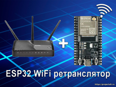
Собрав данный проект, вы сможете превратить ваш ESP32 в WiFi NAT-маршрутизатор. Его можно использовать как:
- Простой расширитель диапазона для существующей сети WiFi
- Настройка дополнительной сети Wi-Fi с другим SSID / паролем для гостевых или IOT-устройств
Функционал и сценарии использования
- Расширение диапазона сети Wi-Fi (ретранслятор)
- Дополнительная гостевая сеть
- Портативное использование с небольшим устройством с низким энергопотреблением (работает от аккумулятора)
- Обход ограничений в общедоступных WiFi, такими как ограничение устройства и скорости
- Сканирование точек доступа
- Удобный пользовательский интерфейс и поддержка мобильных устройств
- Сброс устройства в пользовательском интерфейсе и с помощью Pin-кода / кнопки
- Поддержка соединения в сетях с принудительным отключением
- Защищенный интерфейс с помощью пароля или полного отключения
- Отображение состояния и качества подключения в пользовательском интерфейсе
- Отключение встроенного светодиодного индикатора
Первая загрузка
После первой загрузки NAT-маршрутизатор ESP32 предложит сеть Wi-Fi с открытой точкой доступа и ssid «ESP32_NAT_Router». Настройка может быть выполнена либо через простой веб-интерфейс, либо через консоль.
Веб-интерфейс
Веб-интерфейс позволяет настраивать все параметры. Подключите компьютер или смартфон к SSID Wi-Fi «ESP32_NAT_Router» и перейдите в браузере по адресу «http://192.168.4.1 «. Должна появиться эта страница:
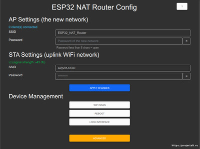
Сначала введите в STA Settings соответствующие значения для восходящей сети WiFi, Оставьте пароль пустым для открытых сетей. Нажмите «Подключиться». ESP32 перезагрузится и подключится к вашему WiFi-маршрутизатору.
Теперь вы можете повторно подключиться и перезагрузить страницу и изменить «Настройки Soft AP». Нажмите «Set», и снова ESP32 перезагрузится. Теперь он готов к пересылке трафика через недавно настроенную программную точку доступа. Имейте в виду, что эти изменения также влияют на интерфейс конфигурации, т. е. для дальнейшей настройки подключитесь к ESP32 через одну из недавно настроенных сетей WiFi.
Скриншоты
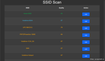
Сканирование точек доступа
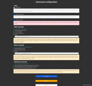
Расширенные настройки
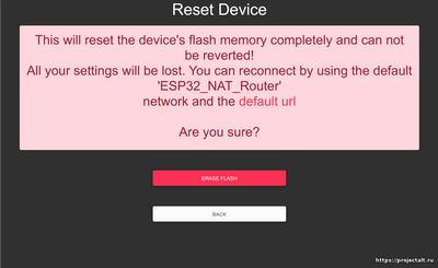
Экран сброса настроек
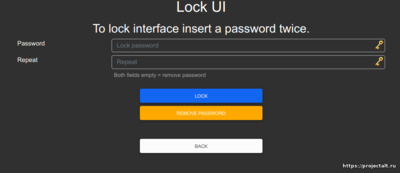
Экран настройки пароля доступа к Веб-интерфейсу
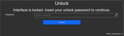
Экран ввода пароля для доступа к Веб-интерфейсу
Обзор подключенных клиентов

Прошивка ESP32
Перед прошивкой ESP32 вам необходимо провести ряд дополнительных действий:
- Распаковать архив с прошивкой
- Скачать и установить esptool
Установка прошивки через ESPTool
Если ваше устройство ранее использовалось для других проектов или вы хотите сбросить все настройки из предыдущей версии c полной потерей данных выполните следующее. Откройте командную строку, перейдите в папку с распакованной прошивкой и введите следующее:
esptool.py write_flash 0x0 esp32nat_extended_full_vX.X.X.bin Альтернативный способ
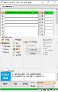
В качестве альтернативы вы можете использовать Espressif’s Flash Download Tools.
Проверьте отмеченные параметры и файлы, как показано ниже (проверьте правильность указания COM-порта).
Выставьте настройки, как показано на скриншоте ниже:
Дополнительная информация
Далее размещена дополнительная информация о тонкой настройке устройства.
Ограничение сканирования Wi-Fi
Из-за технических ограничений клиент не может быть одновременно подключен к устройству и сканировать Wifi. Перед началом сканирования все клиенты будут отключены. После этого начнется сканирование, сохранение в nvram, и устройство перезагрузится. После повторного подключения к устройству вы сможете увидеть проверенные сети. Результат сканирования впоследствии будет удален, но всегда можно повторить попытку сканирования.
Сброс настроек устройства / очистка флэш-памяти
Все настройки можно стереть в пользовательском интерфейсе с помощью кнопки «Erase Flash». Если какая-либо неправильная настройка приводит к неработоспособности устройства, вы также можете подключить GPIO 23 к GND при запуске, чтобы полностью сбросить настройки устройства. GND- и GPIO 23-Pin обычно являются прямыми соседями, поэтому вы можете соединить их любым металлическим предметом, например, скрепкой, ножом, небольшим проводом… Если вы хотите выполнить сброс, вам нужно выключить устройство, соединить GND и GPIO 23 и включить устройство. Через 5 секунд при мостовом соединении устройство сбрасывается, и вы можете удалить мост и перезапустить устройство. Если на вашей плате имеется индикатор, он будет быстро мигать во время этого процесса.
Сигналы встроенного светодиода
Если ESP32 подключен к восходящей точке доступа, то индикатор на плате должен гореть, в противном случае выключен. Если к ESP32 подключены устройства, то индикатор на плате будет мигать столько раз, сколько подключено устройств.
Например:
Одно устройство подключено к ESP32, а ESP32 подключен к восходящему потоку:
*****.*****
К ESP32 подключены два устройства, но ESP32 не подключен к восходящему потоку:
....*.*....
Интерфейс командной строки
Для настройки необходимо использовать последовательную консоль (Putty или GtkTerm со скоростью 115200 бит / с). Используйте команды «set_sta» и «set_ap» для настройки параметров Wi-Fi. Изменения постоянно сохраняются в NVS и применяются после следующего перезапуска. Используйте «show» для отображения текущей конфигурации. Пространство имен NVS для параметров — «esp32_nat»
Введите команду help, чтобы получить полный список всех доступных команд:
help
 Print the list of registered commands

free
 Get the current size of free heap memory

heap
 Get minimum size of free heap memory that was available during program execu
 tion

version
 Get version of chip and SDK

restart
 Software reset of the chip

deep_sleep [-t ] [--io=] [--io_level=<0|1>]
 Enter deep sleep mode. Two wakeup modes are supported: timer and GPIO. If no
 wakeup option is specified, will sleep indefinitely.
 -t, --time= Wake up time, ms
 --io= If specified, wakeup using GPIO with given number
 --io_level=<0|1> GPIO level to trigger wakeup

light_sleep [-t ] [--io=]... [--io_level=<0|1>]...
 Enter light sleep mode. Two wakeup modes are supported: timer and GPIO. Mult
 iple GPIO pins can be specified using pairs of 'io' and 'io_level' arguments
 . Will also wake up on UART input.
 -t, --time= Wake up time, ms
 --io= If specified, wakeup using GPIO with given number
 --io_level=<0|1> GPIO level to trigger wakeup

tasks
 Get information about running tasks

nvs_set   -v
 Set key-value pair in selected namespace.
Examples:
 nvs_set VarName i32 -v
 123
 nvs_set VarName str -v YourString
 nvs_set VarName blob -v 0123456789abcdef
  key of the value to be set
  type can be: i8, u8, i16, u16 i32, u32 i64, u64, str, blob
 -v, --value= value to be stored

nvs_get
 Get key-value pair from selected namespace.
Example: nvs_get VarName i32
  key of the value to be read
  type can be: i8, u8, i16, u16 i32, u32 i64, u64, str, blob

nvs_erase
 Erase key-value pair from current namespace
  key of the value to be erased

nvs_namespace
 Set current namespace
  namespace of the partition to be selected

nvs_list  [-n ] [-t ]
 List stored key-value pairs stored in NVS.Namespace and type can be specified
 to print only those key-value pairs.

Following command list variables stored inside 'nvs' partition, under namespace 'storage' with type uint32_t
 Example: nvs_list nvs -n storage -t u32

  partition name
 -n, --namespace= namespace name
 -t, --type= type can be: i8, u8, i16, u16 i32, u32 i64, u64, str, blob

nvs_erase_namespace
 Erases specified namespace
  namespace to be erased

set_sta
 Set SSID and password of the STA interface
  SSID
  Password

set_sta_static
 Set Static IP for the STA interface
  IP
  Subnet Mask
  Gateway Address

set_ap
 Set SSID and password of the SoftAP
  SSID of AP
  Password of AP

set_ap_ip
 Set IP for the AP interface
  IP

portmap [add|del] [TCP|UDP]
 Add or delete a portmapping to the router
 [add|del] add or delete portmapping
 [TCP|UDP] TCP or UDP port
  external port number
  internal IP
  internal port number

show
 Get status and config of the router
NVS-параметры в пространстве имен esp32
| Параметр | Тип | Значение |
|---|---|---|
| ap_ssid | str | SSID сети точки доступа |
| ap_passwd | str | Пароль сети точки доступа |
| ssid | str | SSID сети STA |
| keep_alive | i32 | Поддержка постоянного соединения |
| led_disabled | i32 | Отключен ли индикатор |
| lock | i32 | Веб-сервер отключен |
| custom_mac | str | Пользовательский Mac-адрес или «случайный» |
| custom_dns | str | Пользовательский DNS-адресом |
| lock_pass | str | Пароль для блокировки пользовательского интерфейса |
| scan_result | str | Временный параметр для последнего результата сканирования |
DNS
Как только ESP32 STA узнал IP-адрес DNS со своего вышестоящего DNS-сервера при первом подключении, он передает его вновь подключенным клиентам. До этого по умолчанию для DNS-сервера, который предлагается клиентам, подключающимся к точке доступа ESP32, установлено значение 192.168.4.1 и настраивается автономный портал. Все разрешения DNS (http) будут разрешены до 192.168.4.1, поэтому любой ввод приведет к начальной странице.
Свежую версию прошивки и актуальную документацию вы всегда сможете найти на github автора проекта
Introduction: WiFi Communication Between Two ESP8266 Based MCU Through the Home Router
Hello Makers!
Some months ago I started to experiment ESP8266 based NodeMCU and Wemos boards. At first I used them (in my previous POI hunter project) as a smarter Arduino, because they have higher clock frequency, more memory and built in «SD card» (SPIFFS).
In my Arduino projects sometimes I had to send messages between two MCUs. I used wired communications (serial, i2C) and wireless (bluetooth, RF transmitter / receiver and nRF24). So there was not question I will face this topic using ESP modules also.
I started to mine the internet for ready samples but I didn’t find an easy solution for MCU-MCU WiFi communication. Finally I started from the basics. According to the description of the Arduino WiFi library and the WiFi library for ESP8266 I made what I wanted.
In the next pages I will share the result with you in two versions. At first two bare MCU will demonstrate the bare minimum solution of the TCP communication. After that I will show an easy application using an additional DHT22 sensor and some OLEDs.
Step 1: Bare Minimum, TCP Communication Between Two ESP8266 MCUs
Yo can see any HW you need in the picture. Only two MCUs (and a PC).
Both MCUs connect to your home WiFi router. (Don’t forget to put your SSID and password into the code before upload the code.) One of the MCUs will be a server and the other will be the client. The client triggers the communication asking the server and the server will send an answer. Modifying the messages you will be able to send anything between the two modules.
Your router will give IP addresses to your MCUs during the connection. Launching the server you will see its IP address in the lower row of the OLED. You have to put this IP into the client’s program, because the client will connect to the server using this address. Running the devices some days later you server will receive different IP address, and you will need to modify the client program again. To avoid this annoying thing give fix IP address to your server.
Things you have to do to launch the server:
- Connect one MCU to a PC with USB cable.
- Open the «wifi_server_01.ino».
- Replace the asterisks «****» with the SSID and the password of your home WiFi router.
- Open the settings of your home WiFi router and choose a free IP address which is out of the DHCP range.
- Set the IP of your server (row15).
- Gateway will be the IP of your WiFi router.
- Upload the program.
- Run the serial monitor of the Arduino IDE.
Things you have to do to launch the client(s):
- Run an additional Arduino IDE.
- Open the «wifi_client_01.ino».
- Replace the asterisks «****» with the SSID and the password of your home WiFi router.
- Put the IP address of your server into the 15th row.
- Upload the program.
- Run the serial monitor for the new Arduino IDE also.
The client connects to the server soon and you have to see the received messages in both terminal windows. During the communication the built in LEDs will flash for a short time.
Step 2: DHT Server With Clients
Here is an application which uses the TCP communication between ESP8266 MCUs.
A Wemos server listens, reads the DHT22 and shows the temperature and its own IP address on a small OLED screen. Two NodeMCU clients trigger the server and receives the temperature value as the answer. During the communication the server’s OLED switches to inverse.
There is only a small modification in the server’s program. After some hour work it sometimes stopped serving the clients. It readed the DHT22 and refreshed the OLED, but clients didn’t received any answer. To solve this problem I started a timer. The program resets it after serving a client. If the timer reaches 30000 (30 seconds), the server disconnects from the WiFi network and reconnects again.
According to the attached schematics you can build the server and client hardware. Uploading the programs you will have a remote thermometer. Modifying the programs you can build your own project in which the ESP8266 based MCUs can communicate with each other.
Of course every device connected to your local network will be able to ask the DHT server. You can see a screenshot about my mobile also.
esp_wifi_repeater
A full functional WiFi repeater (correctly: a WiFi NAT router)
This is an implementation of a WiFi NAT router on the esp8266 and esp8285. It also includes support for a packet filtering firewall with ACLs, port mapping, traffic shaping, hooks for remote monitoring (or packet sniffing), an MQTT management interface, simple GPIO interaction, and power management. For a setup with multiple routers in a mesh to cover a larger area a new mode «Automesh» has been included https://github.com/martin-ger/esp_wifi_repeater#automesh-mode .
If you are looking for a way to integrate the NAT feature into your Arduino project — see https://github.com/martin-ger/lwip_nat_arduino .
A similar basic NAT feature for the ESP32 can be found at: https://github.com/martin-ger/esp32_nat_router.
Typical usage scenarios include:
- Simple range extender for an existing WiFi network
- Battery powered outdoor (mesh) networks
- Setting up an additional WiFi network with different SSID/password for guests
- Setting up a secure and restricted network for IoT devices
- Translating WPA2 Enterprise networks to WPA-PSK
- Monitor probe for WiFi traffic analysis
- Network experiments with routes, ACLs and traffic shaping
- Meshed IoT device with basic I/O capabilities and MQTT control
By default, the ESP acts as STA and as soft-AP and transparently forwards any IP traffic through it. As it uses NAT no routing entries are required neither on the network side nor on the connected stations. Stations are configured via DHCP by default in the 192.168.4.0/24 net and receive their DNS responder address from the existing WiFi network.
Measurements show, that it can achieve about 5 Mbps in both directions, so even streaming is possible.
Some details are explained in this video: https://www.youtube.com/watch?v=OM2FqnMFCLw
First Boot
The esp_wifi_repeater starts with the following default configuration:
- ap_ssid: MyAP, ap_password: none, ap_on: 1, ap_open: 1
- network: 192.168.4.0/24
After first boot (or factory reset) it will offer a WiFi network with an open AP and the ssid «MyAP». It does not yet try to automatically re-connect to an uplink AP (as it does not know a valid ssid or password).
Connect to this WiFi network and do the basic configuration either via a simple web interface or the full config with all options via the console.
Basic Web Config Interface
The web interface allows for the configuration of all parameters required for the basic forwarding functionality. Thanks to rubfi for the major work on that: https://github.com/rubfi/esp_wifi_repeater/ . Point your browser to «http://192.168.4.1». This page should appear:
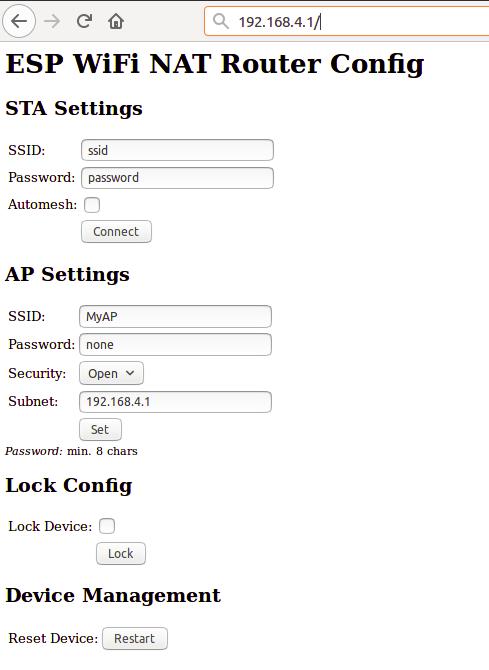
First enter the appropriate values for the uplink WiFi network, the «STA Settings». Use password «none» for open networks. Check the «Automesh» box if and only if you really want to use the automesh mode. Click «Connect». The ESP reboots and will connect to your WiFi router. The status LED should be blinking after some seconds.
If you have selected automesh, you are done with config. Configuring the «Soft AP Settings» is not required as in automesh mode these settings are identical to the «STA Settings». The same ssid will be offered by all connected ESP repeaters.
If you are not using automesh, you can now reload the page and change the «Soft AP Settings». Click «Set» and again the ESP reboots. Now it is ready for forwarding traffic over the newly configured Soft AP. Be aware that these changes also affect the config interface, i.e. to do further configuration, connect to the ESP through one of the newly configured WiFi networks. For access through the Soft AP remember the address of the Soft APs network if you have changed that (the ESP has always the address x.x.x.1 in this network).
If you like, you can mark the «lock» checkbox and click «Lock». Now the config cannot be changed anymore without first unlocking it with the uplink WiFi network’s password (define one even if the network is open).
If you want to enter non-ASCII or special characters in the web interface you have to use HTTP-style hex encoding like «My%20AccessPoint». This will result in a string «My AccessPoint». With this hex encoding you can enter any byte value you like, except for 0 (for C-internal reasons).
If you made a mistake and have lost all contact with the ESP you can still use the serial console to recover it («reset factory», see below).
Command Line Interface
Advanced configuration has to be done via the command line on the console interface. This console is available either via the serial port at 115200 baud or via tcp port 7777 (e.g. «telnet 192.168.4.1 7777» from a connected STA).
Use the following commands for an initial setup:
- set ssid your_home_router’s_SSID
- set password your_home_router’s_password
- set ap_ssid ESP’s_ssid
- set ap_password ESP’s_password
- show (to check the parameters)
- save
- reset
Again, if you want to enter non-ASCII or special characters you can use HTTP-style hex encoding (e.g. «My%20AccessPoint») or, only on the CLI, as shortcut C-style quotes with backslash (e.g. «My\ AccessPoint»). Both methods will result in a string «My AccessPoint».
The command line understands a lot more commands:
Basic Commands
Enough to get it working in nearly all environments.
- help: prints a short help message
- set [ssid|password] value: changes the settings for the uplink AP (WiFi config of your home-router), use password «none» for open networks.
- set [ap_ssid|ap_password] value: changes the settings for the soft-AP of the ESP (for your stations)
- show [config|stats]: prints the current config or some status information and statistics
- save [dhcp]: saves the current config parameters, ACLs, and routing entires [+ the current DHCP leases] to flash
- lock [password]: saves and locks the current config, changes are not allowed. Password can be left open if already set before (Default is the password of the uplink WiFi)
- unlock password: unlocks the config, requires password from the lock command
- reset [factory]: resets the esp, ‘factory’ optionally resets WiFi params to default values (works on a locked device only from serial console)
- quit: terminates a remote session
Advanced Commands
Most of the set-commands are effective only after save and reset.
Any part of a command line input after a single «#» until the end of the line will be treated as a comment and will be ignored.
Automesh Config
- set automesh [0|1]: selects, whether the automesh mode is on or off (default), see details here https://github.com/martin-ger/esp_wifi_repeater#automesh-mode
- set am_threshold dB: sets the threshold for a «bad» connection (in negative dB, default 85, i.e. -85 dB)
- set am_scan_time secs: sets the time interval in seconds the ESP tries in automesh mode to find an uplink AP before going to sleep (0 disabled, default)
- set am_sleep_time secs: sets the time interval in seconds the ESP sleeps in automesh mode if no uplink AP is found (0 disabled, default)
WiFi Config
- set ap_on [0|1]: selects, whether the soft-AP is disabled (ap_on=0) or enabled (ap_on=1, default)
- set ap_open [0|1]: selects, whether the soft-AP uses WPA2-PSK security (ap_open=0, automatic, if an ap_password is set) or open (ap_open=1)
- set auto_connect [0|1]: selects, whether the STA should keep retrying to reconnect to the AP. auto_connect is off (0) after first flashing or after «reset factory». When you enter a new SSID it will be automatically set on (1).
- set ssid_hidden [0|1]: selects, whether the SSID of the soft-AP is hidden (ssid_hidden=1) or visible (ssid_hidden=0, default)
- set phy_mode [1|2|3]: sets the PHY_MODE of the WiFi (1=b, 2=g, 3=n(default))
- set bssid xx:xx:xx:xx:xx:xx: sets the specific BSSID of the uplink AP to connect to (default 00:00:00:00:00:00 which means any)
- set [ap_mac|sta_mac] xx:xx:xx:xx:xx:xx: sets the MAC address of the STA and SOFTAP to a user defined value (bit 0 of the first byte of the MAC address can not be 1)
- set sta_mac random: set a new random STA MAC after each reboot
- set sta_hostname name: sets the name of the STA (visible to the uplink AP)
- set max_clients [1-8]: sets the number of STAs that can connct to the SoftAP (limit of the ESP’s SoftAP implementation is 8, default)
- scan: does a scan for APs
- connect: tries to connect to an AP with the currently configured ssid and password
- disconnect: disconnects from any uplink AP
WPA2 Enterprise Config
- set use_peap[0|1]: selects, whether the STA should connect via simple WPA-PSK (use_peap=0, default) or usinf WPA2 Enterprise (PEAP)
- set peap_identity value: sets the PEAP ‘outer’ identity (the string that is first presented to the RADIUS server, maybe anonymous@yourorg.org)
- peap_username value: sets the PEAP username
- peap_password value: sets the PEAP password
TCP/IP Config
- set network ip-addr: sets the IP address of the internal network, network is always /24, router is always x.x.x.1
- set dns dns-addr: sets a static DNS address that is distributed to clients via DHCP
- set dns dhcp: configures use of the dynamic DNS address from DHCP, default
- set ip ip-addr: sets a static IP address for the STA interface
- set ip dhcp: configures dynamic IP address for the STA interface, default
- set netmask netmask: sets a static netmask for the STA interface
- set gw gw-addr: sets a static gateway address for the STA interface
- set max_nat no_of_entries: sets the size of the NAPT table (default 512)
- set max_portmap no_of_entries: sets the size of the portmap table (default 32)
- set tcp_timeout secs: sets the NAPT timeout for TCP connections (0=default (1800 secs))
- set udp_timeout secs: sets the NAPT timeout for UDP connections (0=default (2 secs))
- show dhcp: prints the current status of the dhcp lease table
Routing
- show route: displays the current routing table
- route clear: clears all static routes
- route add network gw: adds a static route to a network (network given CIDR notation (‘x.x.x.x/n’)) via gateway gw
- route delete network: removes a static route to a network
- interface inX [up|down]: sets the interface state up or down (no IP routing/traffic through down interfaces, default: up)
- set nat [0|1]: selects, whether the soft-AP interface is NATed (nat=1, default) or not (nat=0). Without NAT transparent forwarding of traffic from the internal STAs doesn’t work! Useful mainly in combination with static routing.
- portmap add [TCP|UDP] external_port internal_ip internal_port: adds a port forwarding
- portmap remove [TCP|UDP] external_port: deletes a port forwarding
- nslookup name: starts a DNS lookup for the given name and displays the result
- ping host: checks IP connectivity with ICMP echo request/reply (host as IP address or DNS name)
Firewall/Monitor Config
- acl [from_sta|to_sta|from_ap|to_ap] [TCP|UDP|IP] src-ip [src_port] desr-ip [dest_port] [allow|deny|allow_monitor|deny_monitor]: adds a new rule to the ACL
- acl [from_sta|to_sta|from_ap|to_ap] clear: clears the whole ACL
- show acl: shows the defined ACLs and some stats
- set acl_debug [0|1]: switches ACL debug output on/off — all denied packets will be logged to the terminal
- set [upstream_kbps|downstream_kbps] bitrate: sets a maximum upstream/downstream bitrate (0 = no limit, default)
- set daily_limit limit_in_KB: defined a max. amount of kilobytes that can be transferred by STAs per day (0 = no limit, default)
- set timezone hours_offset: defines the local timezone (required to know, when a day is over at 00:00)
- monitor [on|off|acl] port: starts and stops monitor server on a given port
User Interface Config
- set config_port portno: sets the port number of the console login (default is 7777, 0 disables remote console config)
- set web_port portno: sets the port number of the web config server (default is 80, 0 disables web config)
- set config_access mode: controls the networks that allow config access for console and web (0: no access, 1: only internal, 2: only external, 3: both (default))
GPIO Config
- show gpio: displays the gpio configuration
- gpio [0-16] mode [in|in_pullup|out]: configures a GPIO port of the ESP (saved to flash)
- gpio [0-16] set [high|low]: writes to an output port
- gpio [0-16] set [high|low] for seconds: writes to an output port and reverts after a certain duration
- gpio [0-16] get: reads from an input port
- gpio [0-16] trigger [0-16] [monostable_NO|monostable_NC|bistable_NO|bistable_NC]: links an input port to an output port, either as a monostable normally open (pushbutton triggering when state changes to low), a monostable normally closed (pushbutton triggering when state changes to high), a bistable normally open (switch replicating the input), or a bistable normally closed (switch which state is the opposite of the input)
- gpio [0-16] trigger none: clears the link
Chip Config
- set speed [80|160]: sets the CPU clock frequency (default 160 Mhz)
- sleep seconds: Put ESP into deep sleep for the specified amount of seconds. Valid values between 1 and 4294 (aprox. 71 minutes)
- set status_led GPIOno: selects a GPIO pin for the status LED (default 2, >16 disabled)
- set hw_reset GPIOno: selects a GPIO pin for a hardware factory reset (>16 disabled, default)
- set ap_watchdog secs: sets the AP watchdog timeout — if there are no packets received for secs from the uplink AP the repeater resets («none» = no timeout, default)
- set client_watchdog secs: sets the client watchdog timeout — if there are no packets received for secs from any connected client the repeater resets («none» = no timeout, default)
- set vmin voltage: sets the minimum battery voltage in mV. If Vdd drops below, the ESP goes into deep sleep. If 0, nothing happens
- set vmin_sleep secs: sets the time interval in seconds the ESP sleeps on low voltage
Status LED
In default config GPIO2 is configured to drive a status LED (connected to GND) with the following indications:
- permanently on: started, but not successfully connected to the AP (no valid external IP)
- flashing (1 per second): working, connected to the AP
- unperiodically flashing: working, traffic in the internal network
With «set status_led GPIOno» the GPIO pin can be changed (any value > 16, e.g. «set status_led 255» will disable the status LED completely). When configured to GPIO1, it works with the built-in blue LED on the ESP-01 boards. However, as GPIO1 is also the UART-TX-pin this means, that the serial console is not working. Configuration is then limited to network access.
HW Factory Reset
If you pull low a selected GPIO for more than 3 seconds, the repeater will do a factory reset and restart with default config. With «set hw_reset GPIOno» the GPIO pin can be changed (any value > 16, e.g. «set hw_reset 255» will disable the hw factory reset feature).
For many modules, incl. ESP-01s and NodeMCUs, it is probably a good idea to use GPIO 0 for that, as it is used anyway. However, it is not the default pin, as it might interfere with pulling it down during flashing. Thus, if you want to use an existing push button on GPIO 0 for HW factory reset, configure it with «set hw_reset 0» and «save» after flashing. A factory reset triggered by the HW pin will NOT reset the configured hw_reset GPIO number («reset factory» from console will do).
Port Mapping
In order to allow clients from the external network to connect to server port on the internal network, ports have to be mapped. An external port is mapped to an internal port of a specific internal IP address. Use the «portmap add» command for that. Port mappings can be listed with the «show» command and are saved with the current config.
However, to make sure that the expected device is listening at a certain IP address, it has to be ensured the this devices has the same IP address once it or the ESP is rebooted. To achieve this, either fixed IP addresses can be configured in the devices or the ESP has to remember its DHCP leases. This can be achieved with the «save dhcp» command. It saves the current state and all DHCP leases, so that they will be restored after reboot. DHCP leases can be listed with the «show stats» command.
WPA2 Enterprise (PEAP)
WPA2 Enterprise (PEAP) support has now been included into the project. It allows for a «converter» that translates a WPA2 enterprise network with PEAP authentication into a WPA2-PSK network. This solves a common problem especially in university environments: the local WiFi network is a WPA2 Enterprise network with PEAP-MSCHAPv2 authentication. A very prominent example is the «eduroam»-network that is available at many universities around the world. The problem is, that many IoT devices cannot handle WPA2 Enterprise authentication. So development and demos are difficult. What is very helpful is a «converter» that logs into the WPA2 Enterprise network and offers a simpler WPA-PSK network to its clients.
To use it set the following config parameters: ssid, use_peap, peap_identity, peap_username, and peap_password (you don’t need the usual password parameter). This configuration has to be done (and saved) via the CLI and is not available in the web interface.
The code currently does not check the certificate of the RADIUS-Server. It is vulnerable to MITM-attacks, when somebody sets up a rogue AP and RADIUS server. While the password is not send in plaintext, the used MSCHAPv2 is known to be broken. Also, be aware of the fact that the ESP8266 now contains your enterprise network password. All traffic that is forwarded by it can now be related by the network admin to your account. Do not missuse it and offer it to untrusted others, eg. by configuring an open network. And even when the device is locked, your enterprise network password can be extracted via serial port from the ESP’s flash in plain text.
Automesh Mode
Sometimes you might want to use several esp_wifi_repeaters in a row or a mesh to cover a larger distance or area. Generally, this can be done without any problems with NAT routers, actually you will have several layers of NAT. However, this means connectivity is limited: all nodes can talk to the internet, but generally there’s no direct IP connectivity between the nodes. And, of course, the available bandwidth goes down the more hops you need. But users have reported that even 5 esp_wifi_repeaters in a row work quite well.
In such a setup configuration is quite a time consuming and error-prone activity. To simplify that, the esp_wifi_repeater now has a new mode: «Automesh». Just configure the SSID and the password and switch «automesh» on. (either on the CLI with «set automesh 1» or on the Web interface with just select the checkbox). This will do the following:
Each esp_wifi_repeater configured in that way will automatically offer a WiFi network on the AP with the same SSID/password as it is connected to. Clients can use the same WiFi settings for the original network or the repeated ones. Each esp_wifi_repeater configured with «automesh» will first search for the best other AP to connect to. This is the one which is closest to the original WiFi network and has the best signal strength (RSSI).
The signal strength is easy to measure with a scan, but which is the one closest to the original WiFi network when you see several APs with the same SSID? Therefore the protocol use a somewhat dirty trick: the esp_wifi_repeaters in «automesh» mode manipulate their BSSID (actually, according to the IEEE 802.11 standard this is the «ESSID» as it is an AP, but the SDK calls it «BSSID»), i.e. the MAC address of their AP interface, which is send out with every beacon frame 10 about time times per second. It uses the format: 24:24:mm:rr:rr:rr. «24:24» is just the unique identifier of a repeater (there is a minimal probability that this collides with the real APs MAC, but we can neglect this, as we can change that prefix if really required). «mm» means the «mesh level», this is the distance in hops to the original WiFi network. The last three «rr:rr:rr» are just random numbers to distinguish the various ESPs. The original AP keeps its BSSID, i.e. the one without the prefix «24:24» is recognized as root, called mesh level 0.
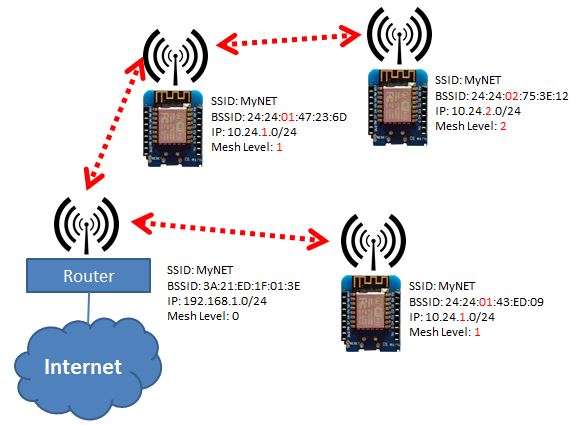
Now each esp_wifi_repeater can learn which other esp_wifi_repeater is the closest to the the original WiFi network, can connect to that, and chose its own BSSID accordingly. Also the IP address of the internal network is adjusted to the mesh level: 10.24.m.0. This creates a tree (a very special mesh) with the original WiFi AP as root and repeating nodes on several mesh levels (actually, it works somewhat similar as the Spanning Tree Protocol (STP) on the link layer or routing on the network layer using a Distance Vector protocol). As soon as an uplink link loss is detected, configuration is restarted. This should avoid loops, as during (re-)configuration also no beacons with an BSSID are sent.
For convenience, the esp_wifi_repeater after «automesh» configuration first tries to check, whether it can connect to an uplink AP. If this fails, even when an AP with the correct SSID has been found, it assumes, the user did a mistake with the password and resets to factory defaults. After it had connected successfully once, it will assume config is correct and keep on trying after connection loss or reset as long as it takes (to avoid a DOS attack with a misconfigured AP).
Tuning Automesh
If there are more than one ESP in range, there might be a trade-off between a shorter «bad» path and a longer «good» path (good and bad in terms of link quality). The parameter am_threshold determines what a bad connection is: if the RSSI in a scan is less than this threshold, a connection is bad and path with one more hop is preferred. I.e. given am_threshold is 85 and there are two automesh nodes detected in the scan: A with level 1 and RSSI -88 dB and B with level 2 and RSSI -60 dB, then a link to A is considered as too bad (-88 dB < —am_threshold) and B is preferred. The new node will become a level 3 node with uplink via B. am_threshold is given as a positive value but means a negative dB. A smaller value is better.
If you want to get more insight into the topology of an automesh network, you might consider to connect all nodes to an MQTT broker and let them publish the «Topology» topic (see below). If you now subscribe on «/WiFi/+/system/Topology» you will get all the node and link infos including the RSSI (of connected ESPs) you need to reconstruct the complete graph and detect weak links in the mesh. The TopologyInfo topic contains the following JSON structure, that can be used to reconstruct a complete graph of an automesh network:
{
"nodeinfo" {
	"id":"ESP_07e37e",
	"ap_mac":"24:24:01:72:c7:f9",
	"sta_mac":"60:01:bc:07:e3:7e",
	"uplink_bssid":"00:1a:54:93:23:0a",
	"ap_ip":"10.24.1.1",
	"sta_ip":"192.168.178.33",
	"rssi":"-66",
	"mesh_level":"1",
	"no_stas":"2"
},
"stas":[
	{"mac":"5c:cf:45:11:7f:13","ip":"10.24.1.2"},
	{"mac":"00:14:22:76:99:c5","ip":"10.24.1.3"}
]
}
Using the two parameters am_scan_time and am_sleep_time power management can be implemented in automesh mode, if you have connected GPIO16 to RST. After booting the esp_wifi_repeater scans for available uplink APs for am_scan_time seconds. If none is found, it goes to deepsleep for am_sleep_time seconds and tries again after reboot (default is 0 = disabled for both parameters).
Monitoring
From the console a monitor service can be started («monitor on [portno]»). This service mirrors the traffic of the internal network in pcap format to a TCP stream. E.g. with a «netcat [external_ip_of_the_repeater] [portno] | sudo wireshark -k -S -i -» from an computer in the external network you can now observe the traffic in the internal network in real time. Use this e.g. to observe with which internet sites your internals clients are communicating. Be aware that this at least doubles the load on the esp and the WiFi network. Under heavy load this might result in some packets being cut short or even dropped in the monitor session. CAUTION: leaving this port open is a potential security issue. Anybody from the local networks can connect and observe your traffic.
Firewall
The ESP router has a integrated basic firewall. ACLs (Access Control Lists) can be applied to the SoftAP interface. This is a cornerstone in IoT security, when the router is used to bring other IoT devices into the internet. It can be used to prevent e.g. third-party IoT devices from «calling home», being misused as malware bots, and to protect your home network with PCs, tablets and phones from being visible to home automation devices.
The four ACL lists are named «from_sta», «to_sta», «from_ap» and «to_ap» for incoming and outgoing packets on both interfaces («sta» means the interfaces to the connectes clients, «ap» the interface to the uplink AP). ACLs are defined in «CISCO IOS style».
The following example is useful for a guest subnet. It allows access to the internet but not to any other local addresses (use your local network range for the xx.xx.xx.xx address). This rule set allows for outgoing local broadcasts (for DHCP) and UDP 53 (DNS), any other packet to the subnet of the upstream router will be blocked, all other packets can pass to the internet:
acl from_sta clear
acl from_sta IP any 255.255.255.255 allow
acl from_sta UDP any any any 53 allow
acl from_sta IP any xx.xx.xx.xx/24 deny
acl from_sta IP any any allow
The next example is more restrictive and is useful when you plan an IoT subnet with very restricted access at the AP of the ESP. It will also allow for outgoing local broadcasts (for DHCP), UDP 53 (DNS), and TCP 1883 (MQTT) to a local broker, but any other packets will be blocked, incl. arbitrary internet access (you may adapt the fourth statement according to your needs to enable other hosts):
acl from_sta clear
acl from_sta IP any 255.255.255.255 allow
acl from_sta UDP any any any 53 allow
acl from_sta TCP any any 192.168.0.0/16 1883 allow
acl from_sta IP any any deny
ACLs for the «to_sta» direction may be defined as well, but this is usually not required, as the reverse direction is quite well protected against unsolicited traffic by the NAT transation.
ACLs consist of filtering rules that are processed for each packet. Each rule consists of a protocol (IP, TCP, or UDP), source address/port, destination address/port, as well as an action «allow» or «deny». In case of plain IP no ports, only addresses are given. IP rules include TCP and UDP packets. Addresses can be given as subnet addresses in the «/» notation, e.g. 192.168.178.0/24. Also «any» can be used as wildcard, it matches on any address or portnumber. A rule is defined by the «acl» command:
- acl [from_sta|to_sta|from_ap|to_ap] [TCP|UDP|IP] src-ip [src_port] desr-ip [dest_port] [allow|deny|allow_monitor|deny_monitor]
The rules are processed top-down in the order of their appearance in the list. The first rule that matches a packet is applied and determies whether a packet is allowed (and forwarded) or denied (and dropped). This means, special cases first, general rules at the end. If there are rules in an ACL all packets that don’t match any rule are denied by default. Thus, the last rule «from_sta IP any any deny» in the example above is not really needed, as it is the default anyway. If an ACL is empty, all packets are allowed.
Definition of ACL rules works also top-down: a new rule is always added at the end of a list. To change an ACL you first have to clear it completely (acl from_sta clear) and then rebuild it. ACLs are saved with the config. «show acl» will print out the ACLs plus statistics on the number of hits for each rule and the overall number of allowed and denied packets.
With the command «set acl_debug 1» a summary of all denied packets is printed to the console. Also, an MQTT topic can publishe this summary. This can be used for firewall configuration to determine which rules are required to get the connected devices working. It also gives a hint if, if unexpected traffic happens (and is denied).
For deeper analysis the monitoring service can be used (even denied packets are reported to the monitor before they are dropped). When the monitor is started with the «monitor acl port» command, ACLs can be used as online filters. All rules that are defined as
«allow_monitor» instead of «allow» and «deny_monitor» instead of «deny» are processed as usual, resulting in allowing of forwarding a packet, but they also send the packet to the monitor. Thus a list of rules that basically «allow» or «allow_monitor» all packets still makes sense, as it can be used to select already during catpure time which packet should be recorded. E.g. a lists:
acl from_sta clear
acl from_sta IP 192.168.0.0/16 any allow_monitor
acl from_sta IP any any allow

acl to_sta clear
acl to_sta IP any 192.168.0.0/16 allow_monitor
cl to_sta IP any any allow
will allow all packets and also select all packets for monitoring that go from a station to the 192.168.0.0/16 (local)subnet and from the 192.168.0.0/16 to a station. Of course such a filter can be applied also after the capture to a full monitoring trace, but if you already know, what you are looking for, these online filters will help to reduce monitoring overhead drastically. It can also be used to debug all deny firewall rules by simply using «deny_monitor» instead of deny.
Static Routes
By default the AP interface is NATed, so that any node connected to the AP will be able to access the outside world transparently via the ESP’s STA interface. So no further action is required, if you are not a real network nerd.
For those of you that are really interested in further network config: the ESP’s lwip IPv4 stack has been enhanced for this project with support for static routes: «show route» displays the routing table with all known routes, including the links to the connected network interfaces (the AP and the STA interface). Routing between these two interfaces works without further configuration. Additional routes to other networks can be set via the «route add network gateway» command, known from Linux boxes or routers. A «save» command writes the current state of the routing table to flash configuration.
Here is a simple example of what can be done with static routes. Given the following network setup with two ESPs connected with the STA interfaces via a central home router:
| 10.0.1.1 AP-ESP1-STA 192.168.1.10 | <-> |Home Router| <-> | 192.168.1.20 STA-ESP2-AP 10.0.2.1|
Each ESP has a second network behind its AP with different network addresses: 10.0.1.0/24 and 10.0.2.0/24. ESP1 can ping to ESP2 to the 192.168.1.20 but not to the 10.0.2.1, as it doesn’t know that it can reach it via the 192.168.1.20. This changes if you add two static routes. On ESP1:
route add 10.0.2.0/24 192.168.1.20
and on ESP2:
route add 10.0.1.0/24 192.168.1.10
Now a «ping 10.0.2.1» on ESP1 will be successful. It is send to 192.168.1.20 and then answered by ESP2.
Now in each network an additional client connects (with addresses 10.0.1.2 and 10.0.2.2):
| STA1 10.0.1.2 | <-> | 10.0.1.1 ESP1 192.168.1.10 | <-> |Home Router| <-> | 192.168.1.20 ESP2 10.0.2.1| <-> | STA2 10.0.2.2 |
Now even client STA1 with the local address 10.0.1.2 can ping to STA2 with 10.0.2.2 as it send its request first to its default router ESP1 and this knows, that all packets to a 10.0.2.0/24 address have to be forwarded to 192.168.1.20. There the ESP2 knows how to send it to STA2. Tthe same applies for the reply in the other direction.
This allows you to configure a multi-star topology of ESPs, where each ESP and its STA clients can direcly reach each other (without any need for portmaps). Configuration of the required routes maybe somewhat painful — but a nice exercise in networking. Next step would be to port a dynamic routing protocol like RIP on the ESP…
Bitrate Limits
By setting upstream_kbps and downstream_kbps to a value other than 0 (0 is the default), you can limit the maximum bitrate of the ESP’s AP. This value is a limit that applies to the traffic of all connected clients. Packets that would exeed the defined bitrate are dropped. The traffic shaper uses the «Token Bucket» algorithm with a bucket size of currently four times the bitrate per seconds, allowing for bursts, when there was no traffic before.
MQTT Support
Since version 1.3 the router has a built-in MQTT client (thanks to Tuan PM for his library https://github.com/tuanpmt/esp_mqtt). This can help to integrate the router/repeater into the IoT. A home automation system can e.g. make decisions based on infos about the currently associated stations, it can switch the repeaters on and off (e.g. based on a time schedule), or it can simply be used to monitor the load. The router can be connected either to a local MQTT broker or to a publicly available broker in the cloud. However it does not currently support TLS encryption.
By default the MQTT client is disabled. It can be enabled by setting the config parameter «mqtt_host» to a hostname different to «none». To configure MQTT you can set the following parameters:
- set mqtt_host IP_or_hostname: IP or hostname of the MQTT broker («none» disables the MQTT client)
- set mqtt_port port: Port of the MQTT broker used for connection (default: 1883)
- set mqtt_qos QoS: MQTT QoS value for publications and subscriptions (0-2, default: 0)
- set mqtt_user username: Username for authentication («none» if no authentication is required at the broker)
- set mqtt_password password: Password for authentication
- set mqtt_id clientId: Id of the client at the broker (default: «ESPRouter_xxxxxx» derived from the MAC address)
- set mqtt_prefix prefix_path: Prefix for all published topics (default: «/WiFi/ESPRouter_xxxxxx/system», again derived from the MAC address)
- set mqtt_command_topic command_topic: Topic subscribed to receive commands, same as from the console. (default: «/WiFi/ESPRouter_xxxxxx/command», «none» disables commands via MQTT)
- set mqtt_interval secs: Set the interval in which the router publishs status topics (default: 15s, 0 disables status publication)
- set mqtt_mask mask_in_hex: Selects which topics are published (default: «ffff» means all)
The MQTT parameters can be displayed with the «show mqtt» command.
The router can publish the following status topics periodically (every mqtt_interval):
- prefix_path/Uptime: System uptime since last reset in s (mask: 0x0020)
- prefix_path/Vdd: Voltage of the power supply in mV (mask: 0x0040)
- prefix_path/Bpsin: KBytes/s from stations into the AP (mask: 0x0800)
- prefix_path/Bpsout: KBytes/s from the AP to stations (mask: 0x0800)
- prefix_path/Bpd: KBytes per day from and to stations (mask: 0x0400)
- prefix_path/Ppsin: Packets/s from stations into the AP (mask: 0x0200)
- prefix_path/Ppsout: Packets/s from the AP to stations (mask: 0x0200)
- prefix_path/Bin: Total bytes from stations into the AP (mask: 0x0100)
- prefix_path/Bout: Total bytes from the AP to stations (mask: 0x0100)
- prefix_path/NoStations: Number of stations currently connected to the AP (mask: 0x2000)
- prefix_path/TopologyInfo: JSON struct with the current topology info of the node (mask: 0x1000)
In addition the repeater can publish on an event basis:
- prefix_path/join: MAC address of a station joining the AP (mask: 0x0008)
- prefix_path/leave: MAC address of a station leaving the AP (mask: 0x0010)
- prefix_path/IP: IP address of the router when received via DHCP (mask: 0x0002)
- prefix_path/ScanResult: Separate topic for the results of a «scan» command (one message per found AP) (mask: 0x0004)
- prefix_path/ACLDeny: A packet has been denied by an ACL rule and has been dropped (mask: 0x0080)
As LWT and status report the repeater publishes:
- prefix_path/status: A retained topic either «online» (as soon as the repeater connects) or «offline» (after connection loss as LWT)
The router can be configured using the following topics:
- command_topic: The router subscribes on this topic and interprets all messages as command lines
- prefix_path/response: The router publishes on this topic the command line output (mask: 0x0001)
If you now want the router to publish e.g. only Vdd, its IP, and the command line output, set the mqtt_mask to 0x0001 | 0x0002 | 0x0040 (= «set mqtt_mask 0043»).
ENC28J60 Ethernet Support
The esp_wifi_repeater now includes support for an ENC28J60 Ethernet NIC connected via SPI (Thanks to Andrew Kroll https://github.com/xxxajk for his great work on getting right), if you switch on the HAVE_ENC28J60 compile option in «user_config.h». The Ethernet interface will support about 1 Mbps when the ESP is running an 160 MHz. Switching the AP interface on and using the Ethernet as uplink will turn the esp_wifi_repeater into a cheap AP for WiFi devices (e.g. other ESPs).
The connection via SPI has to be:
NodeMCU/Wemos  ESP8266      ENC28J60

        D6     GPIO12 <---> MISO
        D7     GPIO13 <---> MOSI
        D5     GPIO14 <---> SCLK
        D8     GPIO15 <---> CS
        D1     GPIO5  <---> INT
	D2     GPIO4  <---> RESET
               Q3/V33 <---> 3.3V
               GND    <---> GND
Short and soldered wires work best. In addition you will need a transistor for decoupling GPIO15, otherwise your ESP will not boot any more, see: https://esp8266hints.wordpress.com/category/ethernet/ . Also, it is important to have a good power supply: the ENC28j60 needs about 160mA when active. For me it fails, if I try to use the 3.3V from the ESP board.
Now you can configure the new Ethernet interface:
- set eth_enable [0|1]: enables/disables an ENC28J60 Ethernet NIC on the SPI bus (default: 0 — disabled)
- set eth_ip ip-addr: sets a static IP address for the ETH interface
- set eth_netmask netmask: sets a static netmask for the ETH interface
- set eth_gw gw-addr: sets a static gateway address for the ETH interface
- set eth_dhcpd [0|1]: starts a DHCP server for dynamic IP addresses on the ETH interface, (default: 0 — disabled)
Power Management
The repeater monitors its current supply voltage (shown in the «show stats» command). This only works, if the 107th byte in esp_init_data_default.bin, named as vdd33_const, is set to 255(0xFF). The easiest way to achieve that, is to write esp_init_data_default_v08_vdd33.bin to flash (see below).
If vmin (in mV, default 0) is set to a value > 0 and the supply voltage drops below this value, it will go into deep sleep mode for vmin_sleep seconds. If you have connected GPIO16 to RST (which is hard to solder on an ESP-01) it will reboot after this interval, try to reconnect, and will continue its measurements. If vmin is saved with the config, it will sleep over and over again, until the supply voltage raises above the threshold. These settings are especially (only?) useful if you have powered the ESP with a (lithium) battery without undercharge protection. Then a value of 2900mV-3000mV is probably helpful, as it reduces power consumption of the ESP to a minimum and you have much more time to recharge or replace the battery before damage. This only makes sense, if you have the ESP connected directly to the battery. If you have additional logic, this will still drain the battery.
You can send the ESP to sleep manually once by using the «sleep» command.
Caution: If you save a vmin value higher than the max supply voltage to flash, the repeater will immediately shutdown every time after reboot. Then you have to wipe out the whole config by flashing blank.bin (or any other file) to 0x0c000.
Building and Flashing
If you have Docker installed, the easiest way to get access to the full build environment is to connect your ESP8266 to /dev/ttyUSB0 and run the image using:
git clone https://github.com/martin-ger/esp_wifi_repeater.git
docker run -it --rm --device=/dev/ttyUSB0 -v $(pwd)/esp_wifi_repeater:/home/esp/esp_wifi_repeater martinfger/iot_devel:1.0
cd esp_wifi_repeater
make
make flash
To set up the build environment from scratch and build this binary download and install the esp-open-sdk (I suggest this version with base NONOS SDK 2.2: https://github.com/xxxajk/esp-open-sdk). Make sure, you can compile and download the included «blinky» example.
Then download this source tree in a separate directory and adjust the BUILD_AREA variable in the Makefile and any desired options in user/user_config.h. Changes of the default configuration can be made in user/config_flash.c. Build the esp_wifi_repeater firmware with «make». «make flash» flashes it onto an esp8266.
The source tree includes a binary version of the liblwip_open plus the required additional includes from my fork of esp-open-lwip and a binary of the rboot tool. No additional install action is required for that. Only if you don’t want to use the precompiled library, checkout the sources from https://github.com/martin-ger/esp-open-lwip . Use it to replace the directory «esp-open-lwip» in the esp-open-sdk tree. «make clean» in the esp_open_lwip dir and once again a «make» in the upper esp_open_sdk directory. This will compile a liblwip_open.a that contains the NAT-features. Replace liblwip_open_napt.a with that binary. Also you might build the «rboot.bin» binary from https://github.com/raburton/rboot and replace it in the root directory of the project.
Update: if you read somewhere in the web install instructions using «0x10000.bin» — due to OTA this has been changed to «0x02000.bin» now.
If you want to use the complete precompiled firmware binaries you can flash them with «esptool.py —port /dev/ttyUSB0 write_flash -fs 4MB -ff 80m -fm dio 0x00000 firmware/0x00000.bin 0x02000 firmware/0x02000.bin» (use -fs 1MB for an ESP-01). For the esp8285 you must use -fs 1MB and -fm dout.
On Windows you can flash it using the «ESP8266 Download Tool» available at https://espressif.com/en/support/download/other-tools. Download the two files 0x00000.bin and 0x02000.bin from the firmware directory. For a generic ESP12, a NodeMCU or a Wemos D1 use the following settings (for an ESP-01 change FLASH SIZE to «8Mbit»):
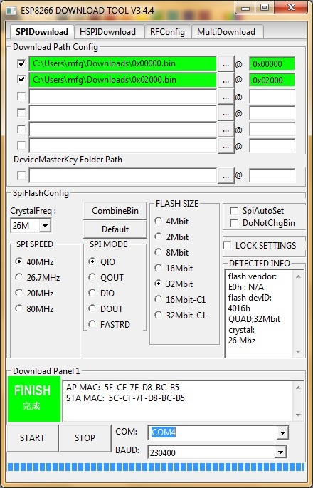
If «QIO» mode fails on your device, try «DIO» instead. Also have a look at the «Detected Info» to check size and mode of the flash chip. If your downloaded firmware still doesn’t start properly, please check with the enclosed checksums whether the binary files are possibly corrupted. If you are in doubt concerning the firmware binaries being corrupted, download the complete repo as zip and extract the binaries from that zip — this avoids HTTP-download problems (e.g. CR-LF conversions).
OTA (Over the air) update support
Based on using the rboot lib: https://github.com/raburton/rboot and thanks to the contribution of christianchristensen.
The build process creates two copies of the esp_wifi_repeater binary in the firmware directory: 0x02000.bin and 0x82000.bin. For an initial installation it is fine just to flash 0x00000.bin (the rboot boot loader) and 0x02000.bin (one copy of the program). The esp_wifi_repeater will work.
If you have at least 1MB of flash you can do an OTA (Over the air) update with another version. I.e. you can interactively load a new binary from the CLI and switch over to it. The other binary is loaded to the currently non active memory location (either 0x02000 (rom0) or 0x82000 (rom1)) and started on success. You can also interactively switch between two installed binaries. The current config will be used for both binaries (as long as its format hasn’t changed).
You can control the OTA features with the following commands:
- show ota: shows the currently active binary and the URL of the next update
- set ota_host hostname: sets hostname or IP address of the OTA server (default: «none»)
- set ota_port portno: sets port number of the OTA server (default: 80)
- ota update: tries to download a new binary (0x02000.bin or 0x82000.bin) via HTTP from ota_host:ota_port and starts it
- ota switch: switches to the other binary (if installed)
To test the OTA feature, configure your ESP (as STA or AP) to be connected to the network with the update server. There start a simple Web server in the firmware directory, e.g.;
cd firmware
python -m SimpleHTTPServer 8080
Set the parameter hostname to the hostname or IP of your computer, set portno to 8080, and «save». Then type on the CLI:
If configured correctly, the update will start and the ESP will reboot with the new binary.
Known Issues
- Due to the limitations of the ESP’s SoftAP implementation, there is a maximum of 8 simultaniously connected stations.
- The ESP8266 requires a good power supply as it produces current spikes of up to 170 mA during transmit (typical average consumption is around 70 mA when WiFi is on). Check the power supply first, if your ESP runs unstable and reboots from time to time. A large capacitor between Vdd and Gnd can help if you experience problems here.
- All firmware published after 17/Oct/2017 have been built with the patched version of the SDK 2.1.0 from Espressif that mitigates the KRACK (https://www.krackattacks.com/ ) attack.
Licenses
The software is open source. Third party source files have their own license header. For all other files the MIT license applies.
Disclosure
Some of the links in this post are affiliate links and if you go through them to make a purchase I will earn a commission. Keep in mind that I link these companies and their products because of their quality and not because of the commission I receive from your purchases. The decision is yours, and whether or not you decide to buy something is completely up to you. Read more
ESP32 development board can be used as WiFi router/repeater with NAT(Network Address Translation), thanks to martin-ger, who developed this great firmware for that purpose.
Can be used as WiFi range extender.
Can be used to setup additional WiFi network with different SSID and password(e.g. for guest or IOT devices).
Setup and installation
- Install esptool.
- Download the project form its GitHub page.
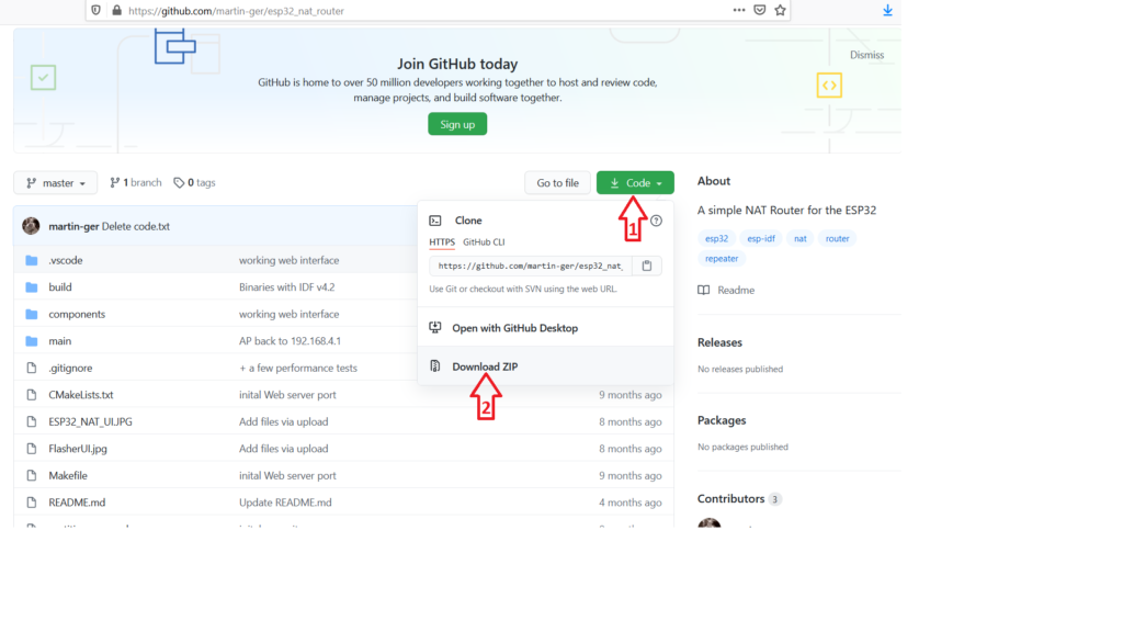
Or using GitHub CLI:
CMD/Terminal
gh repo clone martin-ger/esp32_nat_router- Unzip the project and go inside its main directory.
- Connect your ESP32 to your computer(Get your ESP32 form AliExpress, Gearbest or Banggood).
- Enter the following command:
CMD/Terminal
esptool.py --chip esp32 --port /dev/ttyUSB0 --baud 115200 --before default_reset --after hard_reset write_flash -z --flash_mode dio --flash_freq 40m --flash_size detect 0x1000 build/bootloader/bootloader.bin 0x10000 build/esp32_nat_router.bin 0x8000 build/partitions_example.binFor Linux /dev/ttyUSB0 is the name of the serial port, make sure that you specify the name of the serial port to which ESP32 is connected. While for Windows, serial ports are named something like COM1, COM2 and so on.
First boot
After first power up, your new ESP32 router will create an open WiFi network with SSID “ESP32_NAT_Router”.
Now, you can configure your ESP32 router, either using simple web interface or via the serial console.
Configuration via web interface
- Connect your PC or smartphone to the open WiFi network “ESP32_NAT_Router”.
- Open your browser and go to “http://192.168.4.1“. Subsequently, you should have the following page on your screen:
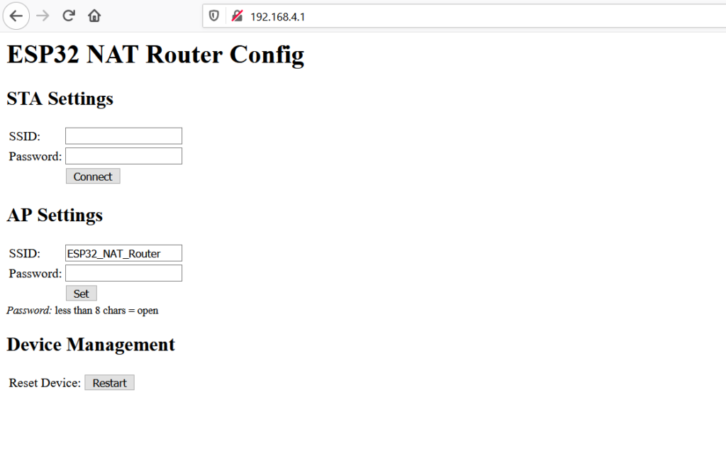
- At first, enter the correct values for the uplink WiFi network, in the STA Settings section. For open networks, leave the password field blank. Then, press Connect. After that, the ESP32 will reboot and connect to your WiFi AP.
- Now, you reconnect and reload the page again, then you modify the AP Settings. So, you enter a new SSID and password for your ESP32 router. Then, click Set, the ESP32 will reboot again and its ready to forward traffic over the newly configured AP. If you want to make further changes, you need to connect to the newly configured AP.
Because the web interface is not secure and not protected with a password, anyone can open it and modify the settings. To get around that, the web interface can be disabled via the command line interface by the following commands:
Serial console
esp32>nvs_namespace esp32_nat
esp32>nvs_set lock str -v 1
After reboot, the web interface is no longer available. To re-enable it, enter the following commands:
Serial console
esp32>nvs_namespace esp32_nat
esp32>nvs_set lock str -v 0
Configuration via command-line interface
- Connect your ESP32 to the USB port of your computer.
- Open the serial port to which your ESP32 is connected, using Putty or any other serial terminal with baud rate set to 115200 bps.
- After successful connection, type the following command, replacing <ssid> and <password> with your uplink WiFi network SSID and password respectively.
Serial console
esp32>set_sta <ssid> <password>- Now, using the “set_ap” command, you set your ESP32 access point SSID and password.
Serial console
esp32>set_ap <ssid> <password>- Finally, type “restart” to reboot the ESP32 with your new configurations.
Notes
- During configuration, If you want to enter non-ASCII or special characters (such as ‘ ‘) within your SSID or password, you have to use HTTP-style hex encoding (e.g. “Access%20Point” results in a string “Access Point”).
- If you made a mistake and you can’t communicate with the ESP32 anymore, you can use the serial console to reconfigure it. The parameter settings are stored in NVS(Non Volatile Storage), which will not be erased by re-flashing the binaries. However, you can wipe it out, by this command
esptool.py -p /dev/ttyUSB0 erase_flash - In the serial console, if you want to show the current configurations use
showcommand. And you can typehelpto get the full list of available commands.
Share
Other articles you may find interesting
Description: Cool glowing animated frame, can be used to indicate activation or as click ripple effect Dependencies: None Mobile support:…
Description: Animated dot spinning around a word that can be used as animated logo or as a loader. Dependencies: None…

Description: Calendar month view that just resembles Window 10’s calendar appearance and animations. Dependencies: JQuery Mobile support: No License: MIT…

Sometimes you need to test your Ethernet cable either to make sure it is working correctly before setup or to…
![]()
In this guide your are going to learn how to embed google’s material design icons to your website in simple,…

In general, network switches are the main building block of wired computer networks. It’s the networking hardware that connects other…
Advertisment
We use cookies on our website to give you the most relevant experience by remembering your preferences and repeat visits. By clicking “Accept”, you consent to the use of ALL the cookies.