Время на прочтение
4 мин
Количество просмотров 54K
Если вы испытываете нехватку физических портов на оборудовании сети передачи данных, в то время как перед вами встала острая необходимость завести второго интернет-провайдера или вывести часть серверов в ДМЗ используя оборудование Cisco Systems, тогда эта статья должна помочь с решением многим начинающим системным администраторам, а также тем, кто недавно приступил к работе с сетями передачи данных и с оборудованием Cisco в частности. Речь пойдет об архитекторе под названием Router-on-a-Stick.
Подобному тому, как коммутатор может разделить локальную сеть на множество VLAN, так и маршрутизатор может использовать один физический интерфейс для создания подмножества логических виртуальных интерфейсов и обеспечить маршрутизацию данных, видео или голоса между ними.
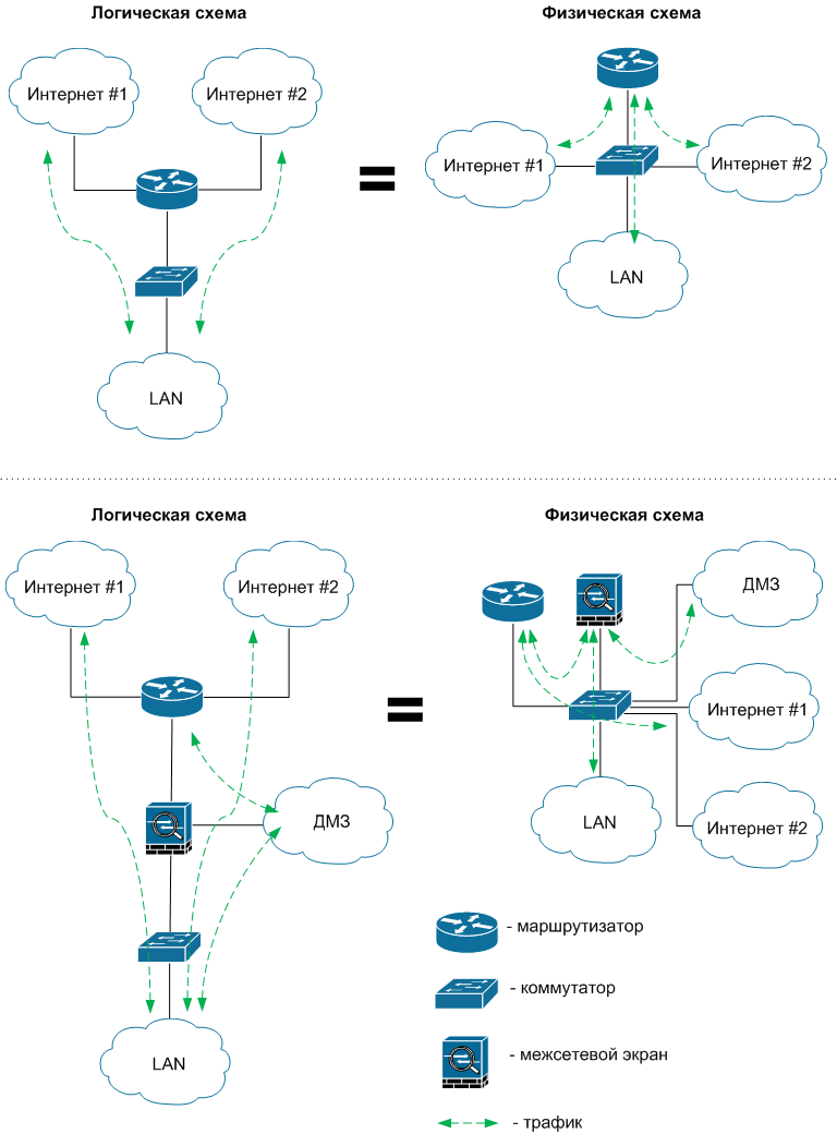
В качестве наглядного примера, на схемах я хочу продемонстрировать некоторые возможные сценарии, которые можно реализовать с помощью одного физического порта и подмножества виртуальных интерфейсов на маршрутизаторе или межсетевом экране Cisco.
Как мы видим, для решения поставленной задачи требуется коммутатор, желательно 3-го уровня. Коммутатор должен обладать достаточной пропускной способностью, чтобы снизить потенциальные задержки передачи пакетов в случае возникновения больших объемов трафика. Если это модульный коммутатор, тогда желательно обзавестись резервным блоком питания и резервным управляющим процессором для него.
Кроме очевидных преимуществ подобной архитектуры, есть также некоторые недостатки, одним из которых является увеличенная в несколько раз нагрузка на отдельно взятый физический порт устройства. Но бывают ситуации, когда обойтись без виртуальных интерфейсов нельзя. Так, например, если немного отвлечься от темы, то невозможно выстроить отказоустойчивую связку двух межсетевых экранов в режиме Active/Passive, если не подключить каждый из них одним физическим линком к коммутатору, а вторым объединив их между собой для обмена служебными данными. В случае выхода из строя одного межсетевого экрана, его место займет второй с идентичной конфигурацией.
Чтобы не оставаться голословным, я приведу пример реализации простейшей модели архитектуры Router-on-a-Stick.
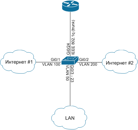
Возьмем упрощенную схему, на которой представлен маршрутизатор, подключенный к коммутатору 2-го уровня. В свою очередь к коммутатору подключены линки от двух интернет-провайдеров и одна внутренняя сеть компании с рабочими станциями и серверами.
Для реализации задуманного, подключим линк от Провайдера #1 к порту Gi0/1 и определим его в VLAN 100, а линк от Провайдера #2 к порту Gi0/2 в VLAN 200. Рабочие станции и сервера будут находиться на портах Gi0/3 — 23 в VLAN 50. Аплинк между коммутатором и маршрутизатором будет на порту Gi0/24, он будет помещен в транк. Схема подключения приведена на рисунке далее:
Конфигурация коммутатора сводится к следующим командам:
telecombook_ru#conf t
telecombook_ru(config)#vlan 50
telecombook_ru(config-vlan)#name DATA
telecombook_ru(config-vlan)#exit
telecombook_ru(config)#vlan 100
telecombook_ru(config-vlan)#name ISP1
telecombook_ru(config-vlan)#exit
telecombook_ru(config)#vlan 200
telecombook_ru(config-vlan)#name ISP2
telecombook_ru(config-vlan)#exit
telecombook_ru(config)#interface Gi0/1
telecombook_ru(config-if)#switchport mode access
telecombook_ru(config-if)#switchport access vlan 100
telecombook_ru(config)#interface Gi0/2
telecombook_ru(config-if)#switchport mode access
telecombook_ru(config-if)#switchport access vlan 200
telecombook_ru(config)#interface range Gi0/3 – 23
telecombook_ru(config-if)#switchport mode access
telecombook_ru(config-if)#switchport access vlan 50
telecombook_ru(config)#interface Gi0/24
telecombook_ru(config-if)#switchport mode trunk
telecombook_ru(config-if)#switchport trunk encapsulation dot1q
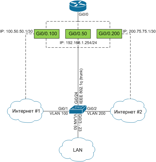
Теперь, когда коммутатор настроен, необходимо указать IP адреса, предоставленные интернет-провайдерами и адрес шлюза для хостов в VLAN 50. Указывать их будем на маршрутизаторе для каждого VLAN с помощью виртуальных интерфейсов. Так, мы разделим один физический интерфейс Gi0/0 на три виртуальных Gi0/0.50, Gi0/0.100, Gi0/0.200 под каждый VLAN и настроим так, как приведено на схеме не забыв про NAT:
Для настройки маршрутизатора применим следующие команды:
telecombook_ru#conf t

telecombook_ru(config)#interface Gi0/0.50

telecombook_ru(config-if)#encapsulation dot1Q 50

telecombook_ru(config-if)#ip address 192.168.1.254 255.255.255.0

telecombook_ru(config-if)#ip nat inside
telecombook_ru(config)#interface Gi0/0.100
telecombook_ru(config-if)#encapsulation dot1Q 100
telecombook_ru(config-if)#ip address 100.50.50.1 255.255.255.252
telecombook_ru(config-if)#ip nat outside
telecombook_ru(config)#interface Gi0/0.200
telecombook_ru(config-if)#encapsulation dot1Q 200
telecombook_ru(config-if)#ip address 200.75.75.1 255.255.255.252
telecombook_ru(config-if)#ip nat outside
telecombook_ru(config)#ip access-list extended nat-traffic
telecombook_ru(config-acl)#10 permit ip 192.168.1.0 0.0.0.255 any
telecombook_ru(config-acl)#exit
telecombook_ru(config)#route-map isp1 permit 10
telecombook_ru(config-route-map)#match ip address nat-traffic
telecombook_ru(config-route-map)#match interface GigabitEthernet0/0.100
telecombook_ru(config-route-map)#exit
telecombook_ru(config)#route-map isp2 permit 10
telecombook_ru(config-route-map)#match ip address nat-traffic
telecombook_ru(config-route-map)#match interface GigabitEthernet0/0.200
telecombook_ru(config-route-map)#exit
telecombook_ru(config)#ip nat inside source route-map isp1 interface GigabitEthernet0/0.100 overload
telecombook_ru(config)#ip nat inside source route-map isp2 interface GigabitEthernet0/0.200 overload
Завершим конфигурацию добавлением двух маршрутов по умолчанию:
telecombook_ru(config)#ip route 0.0.0.0 0.0.0.0 interface Gi0/0.100

telecombook_ru(config)#ip route 0.0.0.0 0.0.0.0 interface Gi0/0.200
Так как маршруты имеют одинаковую метрику, маршрутизатор будет балансировать нагрузку между ними.
Надеюсь, что данный материал когда-нибудь окажется для вас полезным. Спасибо!
From Wikipedia, the free encyclopedia

A router on a stick, also known as a one-armed router,[1][2] is a router that has a single physical or logical connection to a network. It is a method of inter-VLAN routing where one router is connected to a switch via a single cable. The router has physical connections to the broadcast domains where one or more VLANs require the need for routing between them.
Devices on separate VLANs or in a typical local area network are unable to communicate with each other. Therefore, it is often used to forward traffic between locally attached hosts on separate logical routing domains or to facilitate routing table administration, distribution and relay.
Details[edit]

One-armed routers that perform traffic forwarding are often implemented on VLANs. They use a single Ethernet network interface port that is part of two or more Virtual LANs, enabling them to be joined. A VLAN allows multiple virtual LANs to coexist on the same physical LAN. This means that two machines attached to the same switch cannot send Ethernet frames to each other even though they pass over the same wires. If they need to communicate, then a router must be placed between the two VLANs to forward packets, just as if the two LANs were physically isolated. The only difference is that the router in question may contain only a single Ethernet network interface controller (NIC) that is part of both VLANs. Hence, «one-armed». While uncommon, hosts on the same physical medium may be assigned with addresses and to different networks. A one-armed router could be assigned addresses for each network and be used to forward traffic between locally distinct networks and to remote networks through another gateway.
One-armed routers are also used for administration purposes such as route collection, multi hop relay and looking glass servers.
All traffic goes over the trunk twice, so the theoretical maximum sum of up and download speed is the line rate. For a two-armed configuration, uploading does not need to impact download performance significantly. Furthermore, performance may be worse than these limits, such as in the case of half-duplexing and other system limitations.
Applications[edit]
Cases where this setup is used can be found in servers dedicated for prints, files or for segmenting different departments. An example of router on a stick usage is found in Call Manager Express installation, when the Voice over IP network and Cisco IP phone devices have a need to split.[3] Enterprise networks implement this method of separating servers to prevent all users from ‘having equal access privilege to resources’.[4]
Naming[edit]
As the network is separated virtually, the router does not need to be placed adjacent to the devices, rather is it placed to the side in the network topology. The router is connected to the switch by a single cable. Therefore, giving the eponymous ‘stick’ formation. In some institutions, the abbreviation RoaS or ROAS is used instead of router on a stick.[5]
Protocol and design[edit]
Router on a stick relies on one ethernet link that is configured as IEEE 802.1Q trunk link.[6] The trunk is where data flows for the VLANs.
Advantages[edit]
Networks that utilise router on a stick benefit from only requiring one LAN connection to be used for multiple VLANs, i.e. the number of VLANs are not limited by the number of LAN ports available. Separation of network connections do not respond to the physical location of the ports on the router. Thus, this removes the need for multiple cable and wiring management.
As VLANs are segmented, it reduces the amount of traffic flow through a connection.
By separating VLANs, it provides enhanced network security. Network administrators have direct control over multiple broadcast domains. In the event of a malicious user attempting to access any switch port, they will have limited access to the network. The segmentation assists in restricting sensitive traffic that flows within an enterprise.[citation needed]
Certain cases where workgroups are to be created. Users requiring high level of security can be isolated from other networks. Those outside of the VLANs cannot communicate, therefore departments are made independent from each other. Also third party users cannot access the network easily.[citation needed] Networks via router on a stick are independent from their physical locations, therefore sensitive data can be handled without compromise and with ease.
Changes to networks like adding or removing a broadcast domain is achievable by assigning hosts to the appropriate VLANs.
Broadcasts of networks can be managed by multiple hosts, controlled by implementing as many VLANs as required. Therefore, this increases the number of networks while simultaneously decreasing their size.
Implementation of this setup only requires one router.
Disadvantages[edit]
Compared to the alternative of using L3 (Layer 3 switching), the trunk may become a source of congestion as traffic from all VLANs must flow through the trunk link. Modern networks utilise L3 switch which provides greater bandwidth output and functionality. As all network traffic travel over the trunk twice, the trunk can become a major source of congestion, as there is only one trunk connection.[1] Bottleneck can be mitigated if the single interface is combined with other interfaces via link aggregation.[1]
If the router fails, there is no backup and that may become the bottleneck in the network. Since all VLANs must traverse one router, there is a great potential in insufficient bandwidth provided for all network connections.
Before implementing inter-VLAN routing into the network, it requires additional configuration and virtual implementation.[citation needed] Additional latency may be induced when connecting the switch to the router.
Layer 3 switches can route traffic to other switches without the need for a router.[7] It processes data packets faster than routers since the data traverses wire speed. Modern switches have bandwidth ports with greater limits that can improve the overall performance of the network.[8]
See also[edit]
- Route server
- Network switch
References[edit]
- ^ a b c Jensen, Bjorn (11 July 2019). «For Networking Geeks Only: Why Router-on-a-Stick is Good». CEPRO. Cepro. Retrieved 20 November 2020.
- ^ «How To Achieve Router-On-A-Stick Routing Between VLANs On Allied Telesis Routers» (PDF). Retrieved 20 November 2020.
- ^ Wallace, Kevin. «Learning Path: CCNA Routing and Switching 200-125, 1/e». O’Reilly | Safari. Pearson IT Certification. Retrieved 20 November 2020.
- ^ «Router-on-a-Stick Inter-VLAN Routing (4.2) > Inter-VLAN Routing | Cisco Press». www.ciscopress.com. Cisco Networking Academy. Retrieved 2 November 2020.
- ^ Odom, Wendell. «IP Routing in the LAN». Cisco Press. Cisco Press. Retrieved 2 November 2020.
- ^ «Configuring InterVLAN Routing and ISL/802.1Q Trunking on a Catalyst 2900XL/3500XL/2950 Switch Using an External Router». Cisco. Cisco. Retrieved 2 November 2020.
- ^ «Inter VLAN Routing by Layer 3 Switch». GeeksforGeeks. 28 March 2018. Retrieved 20 November 2020.
- ^ Sans, Francisco; Gamess, Eric (12 December 2013). «Analytical Performance Evaluation of Different Switch Solutions». Journal of Computer Networks and Communications. 2013: 1–11. doi:10.1155/2013/953797.
External links[edit]
- one-armed router
Almost all networks in the world use Virtual Local Area Networks nowadays. In our lesson about VLANs we have learned a general rule of thumb that is:
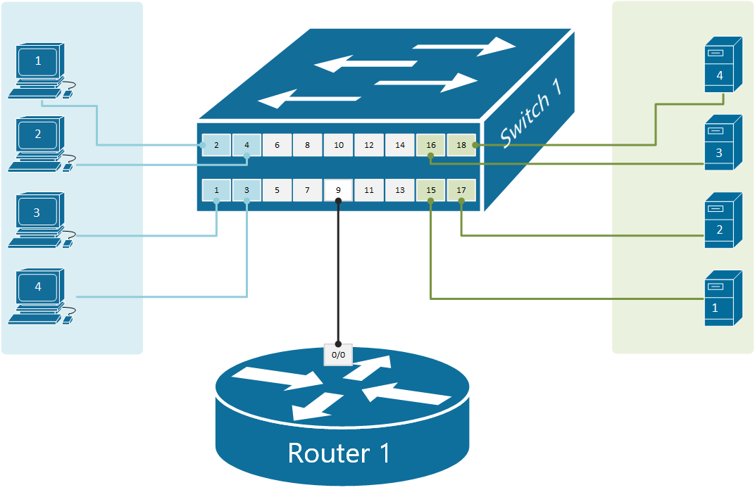
VLAN = Broadcast Domain = SubnetThis means that if we have nodes connected in different VLANs, they most probably are part of different subnets. If we take the topology shown in Figure 1 for example, we have four clients in VLAN10 with addresses in subnet 192.168.1.0/24 and four servers in VLAN20 with addresses in 10.1.0.0/24. Therefore, the communication between the two VLANs must be handled by a device that can perform IP routing between subnets. This device must have an IP address in each network and clients need to then use these addresses as their default gateways respectively.
There are two typical devices that are used to perform routing between VLANs:
- Multilayer Switch (Layer 3 switch) — MLS switches work at both Layer 2 and Layer 3 of the OSI model. They can switch frames and perform IP routing between VLANs. We are examining this InterVLAN routing technique in our next lesson.
- Router — There are two ways to use a router as a device that performs IP routing between VLANs.
- Connecting separate router interface to each VLAN and give each interface an IP address from the respective VLAN subnet. Then it is just a regular routing between networks. We have already discussed this technique in detail in one of our previous lessons.
- Connecting a router with a single link to a switch trunk port and defining sub-interfaces for each vlan. An IP address is then configured on each sub-interface from the respective VLAN. This technique is called router-on-a-stick (ROAS) because there is only one physical link between the router and the switch as you can see in figure 1.
What is router-on-a-stick?
Router-on-a-stick (ROAS) is a technique to connect a router with a single physical link to a switch and perform IP routing between VLANs. From the switch’s perspective, this physical link is configured as a trunk port allowing all VLANs that are going to be routed. From the router’s perspective, this physical interface is represented as multiple virtual sub-interfaces, one for each VLAN. An IP address from each VLAN is then configured on each sub-interface and the router performs IP routing between connected networks.
Comparing this approach to the other scenario where we can use a physical interface for each VLAN. It is obviously a better more scalable technique to use a single trunk link between the switch and the router as shown in figure 1.
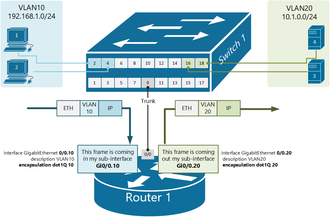
Let’s look more closely at the above physical diagram. There is a single cable connecting Router1 to Switch1. From the switch’s perspective, port 9 is an 802.1q trunk that sends all frames toward the router with a VLAN tag.
From the router’s perspective, all frames are coming in tagged. Therefore, based on this tag the router can differentiate which incoming frames are part of which VLAN. Knowing the VLAN number of each frame, the router knows also which subnet it is part of, because VLAN = Broadcast Domain = Subnet. Having this logic in mind, we can create a virtual interface on the router that treats all frames tagged with VLAN 10 as connected to a virtual interface Gi0/0.10 and all frames tagged with VLAN20 as connected to sub-interface Gi0/0.20.
Router1(config)#interface GigabitEthernet 0/0.10
Router1(config-subif)#encapsulation dot1Q ?
  <1-4094>  IEEE 802.1Q VLAN ID
Router1(config-subif)#encapsulation dot1Q 10
We create a sub-interface using the command interface [interface-name].[sub-interface number]. This creates a virtual interface with the specified number and leads us into the sub-interface configuration mode. There we specify the VLAN ID with the command encapsulation dot1Q [vlan-id], which tells the router that when frames come in the physical interface and are tagged with this particular VLAN number, they should be handled by this sub-interface. Have in mind that the sub-interface number does not have to match the VLAN-ID and could be any random number between 1-429496729. However, the VLAN-ID under the encapsulation command must match the VLAN number on the switch.
Physical diagram
Shown in figure 1 is our physical topology for this example. Note that there is only one physical link between the switch and the router which will be used for all VLANs. Compare this topology to the one from the previous lesson, where there was a physical link for every VLAN.
Configuring the switch
Let’s first start with defining the VLANs on the switch:
Switch1(config)#vlan 10
Switch1(config-vlan)#name CLIENTS
Switch1(config-vlan)#vlan 20
Switch1(config-vlan)#name SERVERS
Switch1(config-vlan)#exit
And then configure the clients’ ports:
Switch1(config)#interface range fastEthernet 0/1-4
Switch1(config-if-range)#description CLIENTS
Switch1(config-if-range)#switchport mode access
Switch1(config-if-range)#switchport access vlan 10
Switch1(config-if-range)#exit

Switch1(config)#interface range fastEthernet 0/15-18
Switch1(config-if-range)#description SERVERS
Switch1(config-if-range)#switchport mode access
Switch1(config-if-range)#switchport access vlan 20
Switch1(config-if-range)#end
The last part is to configure the port where the router is connected to act as an 802.1Q trunk port.
Switch1(config)#interface fastEthernet 0/9
Switch1(config-if)#description LINK-TO-ROUTER1
Switch1(config-if)#switchport mode trunk
Switch1(config-if)#exit
Configuring the router
Let’s see that the router is with default settings. It has three physical interfaces with no configuration at all currently administratively down.
Router>show ip int brief
Interface              IP-Address      OK? Method Status                Protocol
GigabitEthernet0/0     unassigned      YES unset  administratively down down
GigabitEthernet0/1     unassigned      YES unset  administratively down down
GigabitEthernet0/2     unassigned      YES unset  administratively down down
According to our physical diagram, we will have one router interface Gi0/0 connected to the switch on port 9. The first configuration step we must perform is to enable the interface. Just to remind you that — by default, all router interfaces are shut down (administratively down) and all switch interfaces are enabled. This also applies in case we have a device that has switchports (layer 2 interfaces) and router ports (layer 3 interfaces) at the same time. Layer 2 interfaces are enabled by default, layer 3 interfaces are shut down.
Router1#configure terminal
Enter configuration commands, one per line.  End with CNTL/Z.

Router1(config)#interface gigabitEthernet 0/0
Router1(config-if)#no shutdown
%LINK-5-CHANGED:Interface GigabitEthernet0/0, changed state to up
%LINEPROTO-5-UPDOWN:Line protocol on Interface GigabitEthernet0/0, changed state to up
The goal of the router-on-a-stick is to route data between the VLANs using only one physical link. However, the router needs to have an IP address/mask associated with each VLAN because VLAN = Broadcast Domain = Subnet. So to have an address in each VLAN, the router can create virtual routing interfaces associated with each VLAN. These virtual interfaces are called subinterfaces. Let’s configure a sub-interface for VLAN10.
Router1(config)#interface gigabitEthernet 0/0.10
%LINK-5-CHANGED: Interface GigabitEthernet0/0.10, changed state to up
%LINEPROTO-5-UPDOWN: Line protocol on Interface GigabitEthernet0/0.10,
changed state to up

Router1(config-subif)#encapsulation dot1Q 10
Router1(config-subif)#ip address 192.168.1.1 255.255.255.0
Router1(config-subif)#exit
And one more sub-interface for VLAN20.
Router1(config-if)#interface gigabitEthernet 0/0.20
%LINK-5-CHANGED: Interface GigabitEthernet0/0.20, changed state to up
%LINEPROTO-5-UPDOWN: Line protocol on Interface GigabitEthernet0/0.20,
 changed state to up

Router1(config-subif)#encapsulation dot1Q 20
Router1(config-subif)#ip address 10.1.0.1 255.255.255.0
Router1(config-subif)#exit
Now that we have a sub-interface created for each VLAN. The router can forward data between the subnets, as shown in figure 2.
Let’s look at the router’s interface configuration now.
Router1#show ip int brief
Interface              IP-Address      OK? Method Status                Protocol
GigabitEthernet0/0     unassigned      YES unset  up                    up
GigabitEthernet0/0.10  192.168.1.1     YES manual up                    up
GigabitEthernet0/0.20  10.1.0.1        YES manual up                    up
GigabitEthernet0/1     unassigned      YES unset  administratively down down
GigabitEthernet0/2     unassigned      YES unset  administratively down down
Note that no IP address is configured on the physical interface Gi0/0, highlighted in yellow. All layer 3 configuration is applied under the respective sub-interface. If we now check the routing table of router1, we are going to see that it is connected to both networks (VLAN10 192.168.1.0/24 and VLAN20 10.1.0.0/24)
Router1#show ip route
Codes: L - local, C - connected, S - static, R - RIP, M - mobile, B - BGP
       D - EIGRP, EX - EIGRP external, O - OSPF, IA - OSPF inter area
       N1 - OSPF NSSA external type 1, N2 - OSPF NSSA external type 2
       E1 - OSPF external type 1, E2 - OSPF external type 2, E - EGP
       i - IS-IS, L1 - IS-IS level-1, L2 - IS-IS level-2, ia - IS-IS inter area
       * - candidate default, U - per-user static route, o - ODR
       P - periodic downloaded static route

Gateway of last resort is not set

     10.0.0.0/8 is variably subnetted, 2 subnets, 2 masks
C       10.0.1.0/24 is directly connected, GigabitEthernet0/0/0.20
L       10.0.1.1/32 is directly connected, GigabitEthernet0/0/0.20
     192.168.1.0/24 is variably subnetted, 2 subnets, 2 masks
C       192.168.1.0/24 is directly connected, GigabitEthernet0/0/0.10
L       192.168.1.1/32 is directly connected, GigabitEthernet0/0/0.10
The last verification step would be to try a ping between a client in VLAN10 and a server in VLAN20. And sure there is connectivity.
C:\>ping 10.1.0.10

Pinging 10.1.0.10 with 32 bytes of data:

Reply from 10.1.0.10: bytes=32 time<1ms TTL=127
Reply from 10.1.0.10: bytes=32 time<1ms TTL=127
Reply from 10.1.0.10: bytes=32 time<1ms TTL=127
Reply from 10.1.0.10: bytes=32 time<1ms TTL=127

Ping statistics for 10.1.0.10:
    Packets: Sent = 4, Received = 4, Lost = 0 (0% loss),
Approximate round trip times in milli-seconds:
Minimum = 0ms, Maximum = 0ms, Average = 0msРоутер на палочке Cisco – это небольшое устройство, которое предназначено для установки в карман или рюкзак и позволяет подключаться к сети Интернет в любом месте. Такое устройство называется «на палочке» из-за своего компактного и мобильного форм-фактора.
Роутер на палочке Cisco имеет все необходимые функции для обеспечения стабильного и безопасного подключения к Интернету. Он поддерживает различные протоколы и стандарты связи, включая Wi-Fi, Ethernet и Bluetooth, что позволяет легко подключаться к сети и совместно использовать Интернет с другими устройствами.
Использование роутера на палочке Cisco очень просто. Достаточно вставить SIM-карту с доступом к Интернету в устройство, включить его, подключиться к Wi-Fi сети и наслаждаться быстрым и безопасным интернет-соединением в любом месте, где есть сигнал мобильной связи.
Роутер на палочке Cisco идеально подходит для путешественников, удаленных работников и всех, кто ценит свободу и мобильность. Благодаря своим компактным размерам и высокой производительности, он позволяет оставаться на связи в любых обстоятельствах и всегда быть в сети на полную мощность.
Содержание
- Мобильный роутер на палочке Cisco
- Что это такое?
- Главные возможности
- Преимущества
- Использование мобильного роутера на палочке Cisco
Мобильный роутер на палочке Cisco
Этот роутер обладает широким спектром функций и возможностей, которые делают его идеальным выбором для использования в поездках, командировках или просто в повседневной жизни. С помощью мобильного роутера Cisco вы всегда будете на связи и сможете подключить к нему несколько устройств одновременно.
Мобильный роутер на палочке Cisco поддерживает различные стандарты беспроводной связи, такие как 3G, 4G LTE и 5G, что позволяет получать высокоскоростной интернет в любой точке мира. Благодаря этому устройству вы сможете смотреть онлайн-видео, играть в онлайн-игры, обмениваться файлами и использовать другие интернет-ресурсы без проблем и с задержкой.
Мобильный роутер на палочке Cisco легко настраивается и управляется через веб-интерфейс или специальное приложение на смартфоне. Вы можете настроить пароль для доступа к сети, задать ограничение по скорости или выделить отдельную частоту для определенных устройств.
Кроме того, многие модели мобильных роутеров Cisco поддерживают функцию роуминга, что позволяет вам оставаться на связи даже за границей. Это особенно полезно для людей, часто путешествующих по разным странам или отправляющихся в командировки.
Таким образом, мобильный роутер на палочке Cisco — это надежное и удобное устройство, которое обеспечивает стабильное подключение к интернету в любых условиях. Он идеально подходит для тех, кто ценит свободу передвижения и всегда хочет оставаться на связи.
Что это такое?
Это устройство обладает высокой производительностью и поддерживает различные протоколы, такие как IP, TCP, UDP, ARP и другие. Роутер на палочке Cisco также может иметь встроенные функции безопасности, такие как брандмауэр и виртуальная частная сеть (VPN), которые обеспечивают защиту передаваемых данных.
Использование роутера на палочке Cisco позволяет настраивать сетевые параметры, маршрутизацию и фильтрацию данных. Он может быть использован как в домашних условиях, так и в офисных сетях для организации стабильного и надежного интернет-соединения.
|
|
Роутер на палочке Cisco обеспечивает стабильное и надежное подключение к интернету. |

Главные возможности
Роутер на палочке Cisco предоставляет ряд важных возможностей для обеспечения эффективной работы сети:
| 1. Маршрутизация | Роутер на палочке Cisco выполняет функцию маршрутизации пакетов данных. Он способен принимать пакеты с одной сети и пересылать их в другую сеть с учетом оптимального маршрута. |
| 2. Безопасность | Cisco предоставляет надежную защиту данных и сети. Роутеры на палочке обеспечивают аутентификацию, шифрование и контроль доступа к сети, что позволяет защитить информацию от несанкционированного доступа. |
| 3. Управление трафиком | С помощью Cisco можно управлять трафиком в сети. Роутер на палочке предоставляет возможность оптимизировать скорость передачи данных, приоритизировать приложения и контролировать использование полосы пропускания. |
| 4. Виртуальные частные сети (VPN) | С использованием роутера Cisco можно создать безопасное подключение к удаленной локации через интернет с помощью VPN. Это позволяет связывать отдельные сети или компьютеры вместе, создавая защищенную сеть. |
Роутер на палочке Cisco предоставляет еще множество других возможностей, включая поддержку IPv6, балансировку нагрузки, фильтрацию трафика и многое другое. Он является надежным и гибким решением для построения и управления сетью, обеспечивая высокую производительность и безопасность.
Преимущества
Роутер на палочке Cisco имеет ряд преимуществ, которые делают его привлекательным выбором для пользователей:
| 1. Мобильность | Роутер на палочке Cisco представляет собой компактное устройство, которое можно легко взять с собой в путешествие или в офис. Это позволяет подключиться к сети интернет в любом месте, где есть доступ к сотовой связи. |
| 2. Гибкий выбор провайдера | Поскольку роутер на палочке Cisco оснащен слотом для SIM-карты, пользователь может самостоятельно выбрать нужного провайдера мобильного интернета. Это дает возможность сравнивать тарифные планы и выбирать наиболее выгодное предложение. |
| 3. Высокая скорость передачи данных | Роутер на палочке Cisco поддерживает передачу данных по протоколам 3G, 4G LTE и 5G. Это позволяет обеспечить высокую скорость интернета и стабильное соединение для выполнения различных задач, таких как потоковое видео, онлайн-игры и скачивание больших файлов. |
| 4. Легкость настройки | Роутер на палочке Cisco имеет простой процесс настройки, который обычно сводится к вставке SIM-карты и выполнению нескольких шагов в веб-интерфейсе роутера. Это позволяет начать использовать устройство максимально быстро и без особых технических навыков. |
Роутер на палочке Cisco представляет собой удобное и мощное решение для обеспечения интернет-соединения в любом месте. Благодаря его преимуществам, пользователи могут наслаждаться высокой скоростью передачи данных и мобильностью, выбрав наиболее подходящего провайдера. Простота настройки делает его доступным для широкого круга пользователей, независимо от технических навыков.
Использование мобильного роутера на палочке Cisco
Мобильные роутеры на палочке Cisco представляют собой компактные устройства, которые позволяют подключиться к сети интернет в любом месте, где есть сотовая связь. Они оснащены встроенной SIM-картой и поддерживают различные стандарты мобильной связи, такие как 4G и 5G.
Использование мобильного роутера на палочке Cisco очень просто. Вам нужно всего лишь вставить SIM-карту с подходящим тарифом в устройство и включить его. После этого роутер автоматически установит соединение с сотовой сетью и предоставит доступ к интернету.
При помощи мобильного роутера на палочке Cisco вы можете создать собственную беспроводную сеть Wi-Fi, к которой сможет подключиться любое устройство, поддерживающее Wi-Fi. Это может быть ваш ноутбук, смартфон, планшет или другое устройство.
Кроме того, мобильные роутеры на палочке Cisco обладают множеством полезных функций. Например, они поддерживают технологию VPN, которая позволяет создавать безопасное соединение и шифровать передаваемые данные. Также у них есть функция балансировка нагрузки, которая позволяет равномерно распределять трафик между несколькими сетевыми интерфейсами.
Использование мобильного роутера на палочке Cisco особенно удобно, когда вы находитесь в поездке или на отдыхе и не хотите зависеть от общедоступных Wi-Fi сетей или слабого сигнала мобильной связи. С помощью этого устройства вы сможете всегда оставаться на связи и иметь доступ к интернету в любое время и в любом месте.
KnowledgeBase:
Product: UserGate NGFW
Version: 6.1.8, 6.1.9, 5.x
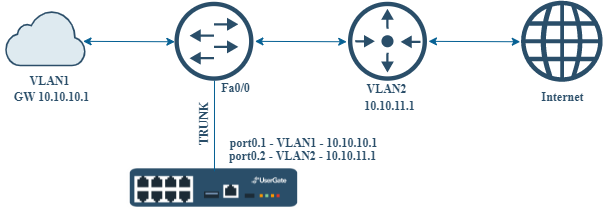
Router-on-a-stick — это термин, часто используемый для описания настройки, которая состоит из маршрутизатора (в нашем случае — устройства UserGate) и коммутатора, подключенных с помощью одного канала Ethernet, настроенного как TRUNK-канал. В этой настройке порты коммутатора принадлежат различным VLAN, и UserGate выполняет всю маршрутизацию между различными сетями/VLAN. Иными словами, на единственном порту UserGate настраиваются подинтерфейсы, которые принадлежат разным VLAN и имеют разные IP адреса. По сути, это соответствует способу внедрения UserGate с двумя интерфейсами, описанному выше, только в качестве интерфейсов используются саб-интерфейсы.
Для конфигурации данной архитектуры произведите следующие настройки.
-
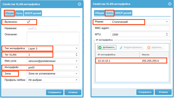
В разделе Сеть ➜ Интерфейсы веб-консоли администратора нажмите на кнопку Добавить и из выпадающего меню выберите Добавить VLAN.
-
В свойствах VLAN-интерфейса в пункте Тип интерфейса установите значение Layer 3.
-
Укажите корректный номер VLAN в пункте Тег VLAN.
-
Выберите интерфейс, который вы скоммутировали для работы.
-
В пункте Зона укажите зону, к которой будет принадлежать создаваемый виртуальный интерфейса.
-
Во вкладке Сеть укажите режим назначения IP-адреса на интерфейс — DHCP или Статический. Если выбран статический режим, то укажите сетевые параметры вручную.
-
Активируйте интерфейс, включив чекбокс Включено.
Повторите описанные действия для других виртуальных интерфейсов.