Summary
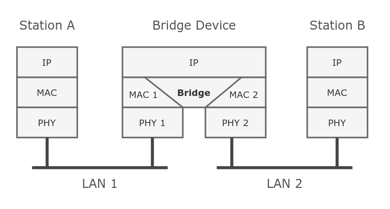
Ethernet-like networks (Ethernet, Ethernet over IP, IEEE 802.11 in ap-bridge or bridge mode, WDS, VLAN) can be connected together using MAC bridges. The bridge feature allows the interconnection of hosts connected to separate LANs (using EoIP, geographically distributed networks can be bridged as well if any kind of IP network interconnection exists between them) as if they were attached to a single LAN. As bridges are transparent, they do not appear in the traceroute list, and no utility can make a distinction between a host working in one LAN and a host working in another LAN if these LANs are bridged (depending on the way the LANs are interconnected, latency and data rate between hosts may vary).
Network loops may emerge (intentionally or not) in complex topologies. Without any special treatment, loops would prevent the network from functioning normally, as they would lead to avalanche-like packet multiplication. Each bridge runs an algorithm that calculates how the loop can be prevented. (R/M)STP allows bridges to communicate with each other, so they can negotiate a loop-free topology. All other alternative connections that would otherwise form loops are put on standby, so that should the main connection fail, another connection could take its place. This algorithm exchanges configuration messages (BPDU — Bridge Protocol Data Unit) periodically, so that all bridges are updated with the newest information about changes in a network topology. (R/M)STP selects a root bridge which is responsible for network reconfiguration, such as blocking and opening ports on other bridges. The root bridge is the bridge with the lowest bridge ID.
Bridge Interface Setup
To combine a number of networks into one bridge, a bridge interface should be created (later, all the desired interfaces should be set up as its ports). One MAC address from slave (secondary) ports will be assigned to the bridge interface, the MAC address will be chosen automatically, depending on «port-number», and it can change after a reboot. To avoid unwanted MAC address changes, it is recommended to disable «auto-mac», and to manually specify MAC by using «admin-mac».
Sub-menu: /interface bridge
| Property | Description |
|---|---|
| add-dhcp-option82 (yes | no; Default: no) | Whether to add DHCP Option-82 information (Agent Remote ID and Agent Circuit ID) to DHCP packets. Can be used together with Option-82 capable DHCP server to assign IP addresses and implement policies. This property only has an effect when dhcp-snooping is set to yes. |
| admin-mac (MAC address; Default: none) | Static MAC address of the bridge. This property only has an effect when auto-mac is set to no. |
| ageing-time (time; Default: 00:05:00) | How long a host’s information will be kept in the bridge database. |
| arp (disabled | enabled | local-proxy-arp | proxy-arp | reply-only; Default: enabled) | Address Resolution Protocol setting
|
| arp-timeout (auto | integer; Default: auto) | How long the ARP record is kept in the ARP table after no packets are received from IP. Value auto equals to the value of arp-timeout in IP/Settings, default is 30s. |
| auto-mac (yes | no; Default: yes) | Automatically select one MAC address of bridge ports as a bridge MAC address, bridge MAC will be chosen from the first added bridge port. After a device reboots, the bridge MAC can change depending on the port-number. |
| comment (string; Default: ) | Short description of the interface. |
| dhcp-snooping (yes | no; Default: no) | Enables or disables DHCP Snooping on the bridge. |
| disabled (yes | no; Default: no) | Changes whether the bridge is disabled. |
| ether-type (0x9100 | 0x8100 | 0x88a8; Default: 0x8100) | Changes the EtherType, which will be used to determine if a packet has a VLAN tag. Packets that have a matching EtherType are considered as tagged packets. This property only has an effect when vlan-filtering is set to yes. |
| fast-forward (yes | no; Default: yes) | Special and faster case of Fast Path which works only on bridges with 2 interfaces (enabled by default only for new bridges). More details can be found in the Fast Forward section. |
| forward-delay (time; Default: 00:00:15) | The time which is spent during the initialization phase of the bridge interface (i.e., after router startup or enabling the interface) in the listening/learning state before the bridge will start functioning normally. |
| frame-types (admit-all | admit-only-untagged-and-priority-tagged | admit-only-vlan-tagged; Default: admit-all) | Specifies allowed frame types on a bridge port. This property only has an effect when vlan-filtering is set to yes. |
| igmp-snooping (yes | no; Default: no) | Enables multicast group and port learning to prevent multicast traffic from flooding all interfaces in a bridge. |
| igmp-version (2 | 3; Default: 2) | Selects the IGMP version in which IGMP membership queries will be generated when the bridge interface is acting as an IGMP querier. This property only has an effect when igmp-snooping and multicast-querier is set to yes. |
| ingress-filtering (yes | no; Default: yes) | Enables or disables VLAN ingress filtering, which checks if the ingress port is a member of the received VLAN ID in the bridge VLAN table. By default, VLANs that don’t exist in the bridge VLAN table are dropped before they are sent out (egress), but this property allows you to drop the packets when they are received (ingress). Should be used with frame-types to specify if the ingress traffic should be tagged or untagged. This property only has an effect when vlan-filtering is set to yes. The setting is enabled by default since RouterOS v7. |
| l2mtu (read-only; Default: ) | L2MTU indicates the maximum size of the frame without a MAC header that can be sent by this interface. The L2MTU value will be automatically set by the bridge and it will use the lowest L2MTU value of any associated bridge port. This value cannot be manually changed. |
| last-member-interval (time; Default: 1s) |
When the last client on the bridge port unsubscribes to a multicast group and the bridge is acting as an active querier, the bridge will send group-specific IGMP/MLD query, to make sure that no other client is still subscribed. The setting changes the response time for these queries. In case no membership reports are received in a certain time period ( If the bridge port is configured with fast-leave, the multicast group is removed right away without sending any queries. This property only has an effect when |
| last-member-query-count (integer: 0..4294967295; Default: 2) | How many times should last-member-interval pass until the IGMP/MLD snooping bridge stops forwarding a certain multicast stream. This property only has an effect when igmp-snooping and multicast-querier is set to yes. |
| max-hops (integer: 6..40; Default: 20) | Bridge count which BPDU can pass in an MSTP enabled network in the same region before BPDU is being ignored. This property only has an effect when protocol-mode is set to mstp. |
| max-message-age (time: 6s..40s; Default: 00:00:20) | Changes the Max Age value in BPDU packets, which is transmitted by the root bridge. A root bridge sends a BPDUs with Max Age set to max-message-age value and a Message Age of 0. Every sequential bridge will increment the Message Age before sending their BPDUs. Once a bridge receives a BPDU where Message Age is equal or greater than Max Age, the BPDU is ignored. This property only has an effect when protocol-mode is set to stp or rstp. |
| membership-interval (time; Default: 4m20s) | The amount of time after an entry in the Multicast Database (MDB) is removed if no IGMP/MLD membership reports are received on a bridge port. This property only has an effect when igmp-snooping is set to yes. |
| mld-version (1 | 2; Default: 1) | Selects the MLD version in which MLD membership queries will be generated, when the bridge interface is acting as an MLD querier. This property only has an effect when the bridge has an active IPv6 address, igmp-snooping and multicast-querier is set to yes. |
| mtu (integer; Default: auto) |
Maximum transmission unit, by default, the bridge will set MTU automatically and it will use the lowest MTU value of any associated bridge port. The default bridge MTU value without any bridge ports added is 1500. The MTU value can be set manually, but it cannot exceed the bridge L2MTU or the lowest bridge port L2MTU. If a new bridge port is added with L2MTU which is smaller than the When adding VLAN interfaces on the bridge, and when VLAN is using higher MTU than default 1500, it is recommended to set manually the MTU of the bridge. |
| multicast-querier (yes | no; Default: no) |
Multicast querier generates periodic IGMP/MLD general membership queries to which all IGMP/MLD capable devices respond with an IGMP/MLD membership report, usually a PIM (multicast) router or IGMP proxy generates these queries. By using this property you can make an IGMP/MLD snooping enabled bridge to generate IGMP/MLD general membership queries. This property should be used whenever there is no active querier (PIM router or IGMP proxy) in a Layer2 network. Without a multicast querier in a Layer2 network, the Multicast Database (MDB) is not being updated, the learned entries will timeout and IGMP/MLD snooping will not function properly. Only untagged IGMP/MLD general membership queries are generated, IGMP queries are sent with IPv4 0.0.0.0 source address, MLD queries are sent with IPv6 link-local address of the bridge interface. The bridge will not send queries if an external IGMP/MLD querier is detected (see the monitoring values This property only has an effect when |
| multicast-router (disabled | permanent | temporary-query; Default: temporary-query) | A multicast router port is a port where a multicast router or querier is connected. On this port, unregistered multicast streams and IGMP/MLD membership reports will be sent. This setting changes the state of the multicast router for a bridge interface itself. This property can be used to send IGMP/MLD membership reports to the bridge interface for further multicast routing or proxying. This property only has an effect when igmp-snooping is set to yes.
|
| name (text; Default: bridgeN) | Name of the bridge interface. |
| priority (integer: 0..65535 decimal format or 0x0000-0xffff hex format; Default: 32768 / 0x8000) | Bridge priority, used by R/STP to determine root bridge, used by MSTP to determine CIST and IST regional root bridge. This property has no effect when protocol-mode is set to none. |
| protocol-mode (none | rstp | stp | mstp; Default: rstp) | Select Spanning tree protocol (STP) or Rapid spanning tree protocol (RSTP) to ensure a loop-free topology for any bridged LAN. RSTP provides a faster spanning tree convergence after a topology change. Select MSTP to ensure loop-free topology across multiple VLANs. Since RouterOS v6.43 it is possible to forward Reserved MAC addresses that are in the 01:80:C2:00:00:0X range, this can be done by setting the protocol-mode to none. |
| pvid (integer: 1..4094; Default: 1) | Port VLAN ID (pvid) specifies which VLAN the untagged ingress traffic is assigned to. It applies e.g. to frames sent from bridge IP and destined to a bridge port. This property only has an effect when vlan-filtering is set to yes. |
| querier-interval (time; Default: 4m15s) | Changes the timeout period for detected querier and multicast-router ports. This property only has an effect when igmp-snooping is set to yes. |
| query-interval (time; Default: 2m5s) | Changes the interval on how often IGMP/MLD general membership queries are sent out when the bridge interface is acting as an IGMP/MLD querier. The interval takes place when the last startup query is sent. This property only has an effect when igmp-snooping and multicast-querier is set to yes. |
| query-response-interval (time; Default: 10s) | The setting changes the response time for general IGMP/MLD queries when the bridge is active as an IGMP/MLD querier. This property only has an effect when igmp-snooping and multicast-querier is set to yes. |
| region-name (text; Default: ) | MSTP region name. This property only has an effect when protocol-mode is set to mstp. |
| region-revision (integer: 0..65535; Default: 0) | MSTP configuration revision number. This property only has an effect when protocol-mode is set to mstp. |
| startup-query-count (integer: 0..4294967295; Default: 2) | Specifies how many times general IGMP/MLD queries must be sent when bridge interface is enabled or active querier timeouts. This property only has an effect when igmp-snooping and multicast-querier is set to yes. |
| startup-query-interval (time; Default: 31s250ms) | Specifies the interval between startup general IGMP/MLD queries. This property only has an effect when igmp-snooping and multicast-querier is set to yes. |
| transmit-hold-count (integer: 1..10; Default: 6) | The Transmit Hold Count used by the Port Transmit state machine to limit the transmission rate. |
| vlan-filtering (yes | no; Default: no) | Globally enables or disables VLAN functionality for the bridge. |
Changing certain properties can cause the bridge to temporarily disable all ports. This must be taken into account whenever changing such properties on production environments since it can cause all packets to be temporarily dropped. Such properties include vlan-filtering, protocol-mode, igmp-snooping, fast-forward and others.
Example
To add and enable a bridge interface that will forward L2 packets:
[admin@MikroTik] > interface bridge add
[admin@MikroTik] > interface bridge print
Flags: X - disabled, R - running
0 R name="bridge1" mtu=auto actual-mtu=1500 l2mtu=65535 arp=enabled arp-timeout=auto mac-address=5E:D2:42:95:56:7F protocol-mode=rstp fast-forward=yes
igmp-snooping=no auto-mac=yes ageing-time=5m priority=0x8000 max-message-age=20s forward-delay=15s transmit-hold-count=6 vlan-filtering=no
dhcp-snooping=no
Bridge Monitoring
To monitor the current status of a bridge interface, use the monitor command.
Sub-menu: /interface bridge monitor
| Property | Description |
|---|---|
| current-mac-address (MAC address) | Current MAC address of the bridge |
| designated-port-count (integer) | Number of designated bridge ports |
| igmp-querier (none | interface & IPv4 address) | Shows a bridge port and source IP address from the detected IGMP querier. Only shows detected external IGMP querier, local bridge IGMP querier (including IGMP proxy and PIM) will not be displayed. Monitoring value appears only when igmp-snooping is enabled. |
| mld-querier (none | interface & IPv6 address) | Shows a bridge port and source IPv6 address from the detected MLD querier. Only shows detected external MLD querier, local bridge MLD querier will not be displayed. Monitoring value appears only when igmp-snooping is enabled and the bridge has an active IPv6 address. |
| multicast-router (yes | no) | Shows if a multicast router is detected on the port. Monitoring value appears only when igmp-snooping is enabled. |
| port-count (integer) | Number of the bridge ports |
| root-bridge (yes | no) | Shows whether the bridge is the root bridge of the spanning tree |
| root-bridge-id (text) | The root bridge ID, which is in form of bridge-priority.bridge-MAC-address |
| root-path-cost (integer) | The total cost of the path to the root-bridge |
| root-port (name) | Port to which the root bridge is connected to |
| state (enabled | disabled) | State of the bridge |
[admin@MikroTik] /interface bridge monitor bridge1
                  state: enabled
    current-mac-address: CC:2D:E0:E4:B3:38
            root-bridge: yes
         root-bridge-id: 0x8000.CC:2D:E0:E4:B3:38
         root-path-cost: 0
              root-port: none
             port-count: 2
  designated-port-count: 2
           fast-forward: no
Spanning Tree Protocol
RouterOS bridge interfaces are capable of running Spanning Tree Protocol to ensure a loop-free and redundant topology. For small networks with just 2 bridges STP does not bring many benefits, but for larger networks properly configured STP is very crucial, leaving STP-related values to default may result in a completely unreachable network in case of an even single bridge failure. To achieve a proper loop-free and redundant topology, it is necessary to properly set bridge priorities, port path costs, and port priorities.
In RouterOS it is possible to set any value for bridge priority between 0 and 65535, the IEEE 802.1W standard states that the bridge priority must be in steps of 4096. This can cause incompatibility issues between devices that do not support such values. To avoid compatibility issues, it is recommended to use only these priorities: 0, 4096, 8192, 12288, 16384, 20480, 24576, 28672, 32768, 36864, 40960, 45056, 49152, 53248, 57344, 61440
STP has multiple variants, currently, RouterOS supports STP, RSTP, and MSTP. Depending on needs, either one of them can be used, some devices are able to run some of these protocols using hardware offloading, detailed information about which device support it can be found in the Hardware Offloading section. STP is considered to be outdated and slow, it has been almost entirely replaced in all network topologies by RSTP, which is backward compatible with STP. For network topologies that depend on VLANs, it is recommended to use MSTP since it is a VLAN aware protocol and gives the ability to do load balancing per VLAN groups. There are a lot of considerations that should be made when designing an STP enabled network, more detailed case studies can be found in the Spanning Tree Protocol article. In RouterOS, the protocol-mode property controls the used STP variant.
By the IEEE 802.1ad standard, the BPDUs from bridges that comply with IEEE 802.1Q are not compatible with IEEE 802.1ad bridges, this means that the same bridge VLAN protocol should be used across all bridges in a single Layer2 domain, otherwise (R/M)STP will not function properly.
Per-port STP
There might be certain situations where you want to limit STP functionality on single or multiple ports. Below you can find some examples for different use cases.
Be careful when changing the default (R/M)STP functionality, make sure you understand the working principles of STP and BPDUs. Misconfigured (R/M)STP can cause unexpected behavior.
Create edge ports
Setting a bridge port as an edge port will restrict it from sending BPDUs and will ignore any received BPDUs:
/interface bridge
add name=bridge1
/interface bridge port
add bridge=bridge1 interface=ether1 edge=yes
add bridge=bridge1 interface=ether2
Drop received BPDUs
The bridge filter or NAT rules cannot drop BPDUs when the bridge has STP/RSTP/MSTP enabled due to the special processing of BPDUs. However, dropping received BPDUs on a certain port can be done on some switch chips using ACL rules:
On CRS3xx:
/interface ethernet switch rule
add dst-mac-address=01:80:C2:00:00:00/FF:FF:FF:FF:FF:FF new-dst-ports="" ports=ether1 switch=switch1
On CRS1xx/CRS2xx with Access Control List (ACL) support:
/interface ethernet switch acl
add action=drop mac-dst-address=01:80:C2:00:00:00 src-ports=ether1
In this example all received BPDUs on ether1 are dropped.
If you intend to drop received BPDUs on a port, then make sure to prevent BPDUs from being sent out from the interface that this port is connected to. A root bridge always sends out BPDUs and under normal conditions is waiting for a more superior BPDU (from a bridge with a lower bridge ID), but the bridge must temporarily disable the new root-port when transitioning from a root bridge to a designated bridge. If you have blocked BPDUs only on one side, then a port will flap continuously.
Enable BPDU guard
In this example, if ether1 receives a BPDU, it will block the port and will require you to manually re-enable it.
/interface bridge
add name=bridge1
/interface bridge port
add bridge=bridge1 interface=ether1 bpdu-guard=yes
add bridge=bridge1 interface=ether2
Bridge Settings
Under the bridge settings menu, it is possible to control certain features for all bridge interfaces and monitor global bridge counters.
Sub-menu: /interface bridge settings
| Property | Description |
|---|---|
| use-ip-firewall (yes | no; Default: no) | Force bridged traffic to also be processed by prerouting, forward, and postrouting sections of IP routing (see more details on Packet Flow article). This does not apply to routed traffic. This property is required in case you want to assign Simple Queues or global Queue Tree to traffic in a bridge. Property use-ip-firewall-for-vlan is required in case bridge vlan-filtering is used. |
| use-ip-firewall-for-pppoe (yes | no; Default: no) | Send bridged un-encrypted PPPoE traffic to also be processed by IP/Firewall. This property only has an effect when use-ip-firewall is set to yes. This property is required in case you want to assign Simple Queues or global Queue Tree to PPPoE traffic in a bridge. |
| use-ip-firewall-for-vlan (yes | no; Default: no) | Send bridged VLAN traffic to also be processed by IP/Firewall. This property only has an effect when use-ip-firewall is set to yes. This property is required in case you want to assign Simple Queues or global Queue Tree to VLAN traffic in a bridge. |
| allow-fast-path (yes | no; Default: yes) | Whether to enable a bridge Fast Path globally. |
| bridge-fast-path-active (yes | no; Default: ) | Shows whether a bridge FastPath is active globally, Fast Path status per bridge interface is not displayed. |
| bridge-fast-path-packets (integer; Default: ) | Shows packet count forwarded by bridge Fast Path. |
| bridge-fast-path-bytes (integer; Default: ) | Shows byte count forwarded by bridge Fast Path. |
| bridge-fast-forward-packets (integer; Default: ) | Shows packet count forwarded by bridge Fast Forward. |
| bridge-fast-forward-bytes (integer; Default: ) | Shows byte count forwarded by bridge Fast Forward. |
In case you want to assign Simple Queues or global Queue Trees to traffic that is being forwarded by a bridge, then you need to enable the use-ip-firewall property. Without using this property the bridge traffic will never reach the postrouting chain, Simple Queues and global Queue Trees are working in the postrouting chain. To assign Simple Queues or global Queue Trees for VLAN or PPPoE traffic in a bridge you should enable appropriate properties as well.
Port Settings
Port submenu is used to add interfaces in a particular bridge.
Sub-menu: /interface bridge port
| Property | Description |
|---|---|
| auto-isolate (yes | no; Default: no) | When enabled, prevents a port moving from discarding into forwarding state if no BPDUs are received from the neighboring bridge. The port will change into a forwarding state only when a BPDU is received. This property only has an effect when protocol-mode is set to rstp or mstp and edge is set to no. |
| bpdu-guard (yes | no; Default: no) | Enables or disables BPDU Guard feature on a port. This feature puts the port in a disabled role if it receives a BPDU and requires the port to be manually disabled and enabled if a BPDU was received. Should be used to prevent a bridge from BPDU related attacks. This property has no effect when protocol-mode is set to none. |
| bridge (name; Default: none) | The bridge interface where the respective interface is grouped in. |
| broadcast-flood (yes | no; Default: yes) | When enabled, bridge floods broadcast traffic to all bridge egress ports. When disabled, drops broadcast traffic on egress ports. Can be used to filter all broadcast traffic on an egress port. Broadcast traffic is considered as traffic that uses FF:FF:FF:FF:FF:FF as destination MAC address, such traffic is crucial for many protocols such as DHCP, ARP, NDP, BOOTP (Netinstall), and others. This option does not limit traffic flood to the CPU. |
| edge (auto | no | no-discover | yes | yes-discover; Default: auto) | Set port as edge port or non-edge port, or enable edge discovery. Edge ports are connected to a LAN that has no other bridges attached. An edge port will skip the learning and the listening states in STP and will transition directly to the forwarding state, this reduces the STP initialization time. If the port is configured to discover edge port then as soon as the bridge detects a BPDU coming to an edge port, the port becomes a non-edge port. This property has no effect when protocol-mode is set to none.
|
| fast-leave (yes | no; Default: no) | Enables IGMP/MLD fast leave feature on the bridge port. The bridge will stop forwarding multicast traffic to a bridge port when an IGMP/MLD leave message is received. This property only has an effect when igmp-snooping is set to yes. |
| frame-types (admit-all | admit-only-untagged-and-priority-tagged | admit-only-vlan-tagged; Default: admit-all) | Specifies allowed ingress frame types on a bridge port. This property only has an effect when vlan-filtering is set to yes. |
| ingress-filtering (yes | no; Default: yes) | Enables or disables VLAN ingress filtering, which checks if the ingress port is a member of the received VLAN ID in the bridge VLAN table. Should be used with frame-types to specify if the ingress traffic should be tagged or untagged. This property only has effect when vlan-filtering is set to yes. The setting is enabled by default since RouterOS v7. |
| learn (auto | no | yes; Default: auto) | Changes MAC learning behavior on a bridge port
|
| multicast-router (disabled | permanent | temporary-query; Default: temporary-query) | A multicast router port is a port where a multicast router or querier is connected. On this port, unregistered multicast streams and IGMP/MLD membership reports will be sent. This setting changes the state of the multicast router for bridge ports. This property can be used to send IGMP/MLD membership reports to certain bridge ports for further multicast routing or proxying. This property only has an effect when igmp-snooping is set to yes.
|
| horizon (integer 0..429496729; Default: none) | Use split horizon bridging to prevent bridging loops. Set the same value for a group of ports, to prevent them from sending data to ports with the same horizon value. Split horizon is a software feature that disables hardware offloading. Read more about Bridge split horizon. |
| hw (yes | no; Default: yes) | Allows to enable or disable hardware offloading on interfaces capable of HW offloading. For software interfaces like EoIP or VLAN this setting is ignored and has no effect. Certain bridge or port functions can automatically disable HW offloading, use the print command to see whether the «H» flag is active. |
| internal-path-cost (integer: 0..4294967295; Default: 10) | Path cost to the interface for MSTI0 inside a region. This property only has effect when protocol-mode is set to mstp. |
| interface (name; Default: none) | Name of the interface. |
| path-cost (integer: 0..4294967295; Default: 10) | Path cost to the interface, used by STP to determine the best path, used by MSTP to determine the best path between regions. This property has no effect when protocol-mode is set to none. |
| point-to-point (auto | yes | no; Default: auto) | Specifies if a bridge port is connected to a bridge using a point-to-point link for faster convergence in case of failure. By setting this property to yes, you are forcing the link to be a point-to-point link, which will skip the checking mechanism, which detects and waits for BPDUs from other devices from this single link. By setting this property to no, you are expecting that a link can receive BPDUs from multiple devices. By setting the property to yes, you are significantly improving (R/M)STP convergence time. In general, you should only set this property to no if it is possible that another device can be connected between a link, this is mostly relevant to Wireless mediums and Ethernet hubs. If the Ethernet link is full-duplex, auto enables point-to-point functionality. This property has no effect when protocol-mode is set to none. |
| priority (integer: 0..240; Default: 128) | The priority of the interface, used by STP to determine the root port, used by MSTP to determine root port between regions. |
| pvid (integer 1..4094; Default: 1) | Port VLAN ID (pvid) specifies which VLAN the untagged ingress traffic is assigned to. This property only has an effect when vlan-filtering is set to yes. |
| restricted-role (yes | no; Default: no) | Enable the restricted role on a port, used by STP to forbid a port from becoming a root port. This property only has an effect when protocol-mode is set to mstp. |
| restricted-tcn (yes | no; Default: no) | Disable topology change notification (TCN) sending on a port, used by STP to forbid network topology changes to propagate. This property only has an effect when protocol-mode is set to mstp. |
| tag-stacking (yes | no; Default: no) | Forces all packets to be treated as untagged packets. Packets on ingress port will be tagged with another VLAN tag regardless if a VLAN tag already exists, packets will be tagged with a VLAN ID that matches the pvid value and will use EtherType that is specified in ether-type. This property only has effect when vlan-filtering is set to yes. |
| trusted (yes | no; Default: no) | When enabled, it allows forwarding DHCP packets towards the DHCP server through this port. Mainly used to limit unauthorized servers to provide malicious information for users. This property only has an effect when dhcp-snooping is set to yes. |
| unknown-multicast-flood (yes | no; Default: yes) |
Changes the multicast flood option on bridge port, only controls the egress traffic. When enabled, the bridge allows flooding multicast packets to the specified bridge port, but when disabled, the bridge restricts multicast traffic from being flooded to the specified bridge port. The setting affects all multicast traffic, this includes non-IP, IPv4, IPv6 and the link-local multicast ranges (e.g. 224.0.0.0/24 and ff02::1). Note that when When using this setting together with |
| unknown-unicast-flood (yes | no; Default: yes) |
Changes the unknown unicast flood option on bridge port, only controls the egress traffic. When enabled, the bridge allows flooding unknown unicast packets to the specified bridge port, but when disabled, the bridge restricts unknown unicast traffic from being flooded to the specified bridge port. If a MAC address is not learned in the host table, then the traffic is considered as unknown unicast traffic and will be flooded to all ports. MAC address is learned as soon as a packet on a bridge port is received and the source MAC address is added to the bridge host table. Since it is required for the bridge to receive at least one packet on the bridge port to learn the MAC address, it is recommended to use static bridge host entries to avoid packets being dropped until the MAC address has been learned. |
Example
To group ether1 and ether2 in the already created bridge1 interface.
[admin@MikroTik] /interface bridge port add bridge=bridge1 interface=ether1
[admin@MikroTik] /interface bridge port add bridge=bridge1 interface=ether2
[admin@MikroTik] /interface bridge port print
Flags: X - disabled, I - inactive, D - dynamic, H - hw-offload
 #     INTERFACE       BRIDGE       HW  PVID PRIORITY  PATH-COST INTERNAL-PATH-COST    HORIZON
 0     ether1          bridge1      yes  100     0x80         10                 10       none
 1     ether2          bridge1      yes  200     0x80         10                 10       none
Interface lists
Starting with RouterOS v6.41 it possible to add interface lists as a bridge port and sort them. Interface lists are useful for creating simpler firewall rules. Below is an example how to add an interface list to a bridge:
/interface list
add name=LAN1
add name=LAN2
/interface list member
add interface=ether1 list=LAN1
add interface=ether2 list=LAN1
add interface=ether3 list=LAN2
add interface=ether4 list=LAN2
/interface bridge port
add bridge=bridge1 interface=LAN1
add bridge=bridge1 interface=LAN2
Ports from an interface list added to a bridge will show up as dynamic ports:
[admin@MikroTik] /interface bridge port> pr
Flags: X - disabled, I - inactive, D - dynamic, H - hw-offload
 #     INTERFACE       BRIDGE       HW  PVID PRIORITY  PATH-COST INTERNAL-PATH-COST    HORIZON
 0     LAN1            bridge1      yes    1     0x80         10                 10       none
 1  D  ether1          bridge1      yes    1     0x80         10                 10       none
 2  D  ether2          bridge1      yes    1     0x80         10                 10       none
 3     LAN2            bridge1      yes    1     0x80         10                 10       none
 4  D  ether3          bridge1      yes    1     0x80         10                 10       none
 5  D  ether4          bridge1      yes    1     0x80         10                 10       none
It is also possible to sort the order of lists in which they appear. This can be done using the move command. Below is an example of how to sort interface lists:
[admin@MikroTik] > /interface bridge port move 3 0
[admin@MikroTik] > /interface bridge port print
Flags: X - disabled, I - inactive, D - dynamic, H - hw-offload
 #     INTERFACE       BRIDGE       HW  PVID PRIORITY  PATH-COST INTERNAL-PATH-COST    HORIZON
 0     LAN2            bridge1      yes    1     0x80         10                 10       none
 1  D  ether3          bridge1      yes    1     0x80         10                 10       none
 2  D  ether4          bridge1      yes    1     0x80         10                 10       none
 3     LAN1            bridge1      yes    1     0x80         10                 10       none
 4  D  ether1          bridge1      yes    1     0x80         10                 10       none
 5  D  ether2          bridge1      yes    1     0x80         10                 10       none
The second parameter when moving interface lists is considered as «before id», the second parameter specifies before which interface list should be the selected interface list moved. When moving the first interface list in place of the second interface list, then the command will have no effect since the first list will be moved before the second list, which is the current state either way.
Bridge Port Monitoring
To monitor the current status of bridge ports, use the monitor command.
Sub-menu: /interface bridge port monitor
| Property | Description |
|---|---|
| edge-port (yes | no) | Whether the port is an edge port or not. |
| edge-port-discovery (yes | no) | Whether the port is set to automatically detect edge ports. |
| external-fdb (yes | no) | Whether the registration table is used instead of a forwarding database. |
| forwarding (yes | no) | Shows if the port is not blocked by (R/M)STP. |
| hw-offload-group (switchX) | Switch chip used by the port. |
| learning (yes | no) | Shows whether the port is capable of learning MAC addresses. |
| multicast-router (yes | no) | Shows if a multicast router is detected on the port. Monitoring value appears only when igmp-snooping is enabled. |
| port-number (integer 1..4095) | A port-number will be assigned in the order that ports got added to the bridge, but this is only true until reboot. After reboot, the internal port numbering will be used. |
| point-to-point-port (yes | no) | Whether the port is connected to a bridge port using full-duplex (yes) or half-duplex (no). |
| role (designated | root port | alternate | backup | disabled) |
(R/M)STP algorithm assigned the role of the port:
|
| sending-rstp (yes | no) | Whether the port is using RSTP or MSTP BPDU types. A port will transit to STP type when RSTP/MSTP enabled port receives an STP BPDU. This settings does not indicate whether the BDPUs are actually sent. |
| status (in-bridge | inactive) | Port status:
|
[admin@MikroTik] /interface bridge port monitor [find interface=ether1]
            interface: ether1
               status: in-bridge
          port-number: 1
                 role: designated-port
            edge-port: yes
  edge-port-discovery: yes
  point-to-point-port: yes
         external-fdb: no
         sending-rstp: yes
             learning: yes
           forwarding: yes
Hosts Table
MAC addresses that have been learned on a bridge interface can be viewed in the host menu. Below is a table of parameters and flags that can be viewed.
Sub-menu: /interface bridge host
| Property | Description |
|---|---|
| bridge (read-only: name) | The bridge the entry belongs to |
| disabled (read-only: flag) | Whether the static host entry is disabled |
| dynamic (read-only: flag) | Whether the host has been dynamically created |
| external (read-only: flag) | Whether the host has been learned using an external table, for example, from a switch chip or Wireless registration table. Adding a static host entry on a hardware-offloaded bridge port will also display an active external flag |
| invalid (read-only: flag) | Whether the host entry is invalid, can appear for statically configured hosts on already removed interface |
| local (read-only: flag) | Whether the host entry is created from the bridge itself (that way all local interfaces are shown) |
| mac-address (read-only: MAC address) | Host’s MAC address |
| on-interface (read-only: name) | Which of the bridged interfaces the host is connected to |
Monitoring
To get the active hosts table:
[admin@MikroTik] /interface bridge host print
Flags: X - disabled, I - invalid, D - dynamic, L - local, E - external
 #       MAC-ADDRESS        VID ON-INTERFACE            BRIDGE
 0   D   B8:69:F4:C9:EE:D7      ether1                  bridge1
 1   D   B8:69:F4:C9:EE:D8      ether2                  bridge1
 2   DL  CC:2D:E0:E4:B3:38      bridge1                 bridge1
 3   DL  CC:2D:E0:E4:B3:39      ether2                  bridge1
Static entries
Since RouterOS v6.42 it is possible to add a static MAC address entry into the host table. This can be used to forward a certain type of traffic through a specific port. Another use case for static host entries is for protecting the device resources by disabling the dynamic learning and rely only on configured static host entries. Below is a table of possible parameters that can be set when adding a static MAC address entry into the host table.
Sub-menu: /interface bridge host
| Property | Description |
|---|---|
| bridge (name; Default: none) | The bridge interface to which the MAC address is going to be assigned. |
| disabled (yes | no; Default: no) | Disables/enables static MAC address entry. |
| interface (name; Default: none) | Name of the interface. |
| mac-address (MAC address; Default: ) | MAC address that will be added to the host table statically. |
| vid (integer: 1..4094; Default: ) | VLAN ID for the statically added MAC address entry. |
For example, if it was required that all traffic destined to 4C:5E:0C:4D:12:43 is forwarded only through ether2, then the following commands can be used:
/interface bridge host
add bridge=bridge interface=ether2 mac-address=4C:5E:0C:4D:12:43
Multicast Table
When IGMP/MLD snooping is enabled, the bridge will start to listen to IGMP/MLD communication, create multicast database (MDB) entries and make forwarding decisions based on the received information. Packets with link-local multicast destination addresses 224.0.0.0/24 and ff02::1 are not restricted and are always flooded on all ports and VLANs. To see learned multicast database entries, use the print command.
Sub-menu: /interface bridge mdb
|
Property |
Description |
|---|---|
| bridge (read-only: name) | Shows the bridge interface the entry belongs to. |
| group (read-only: ipv4 | ipv6 address) | Shows a multicast group address. |
| on-ports (read-only: name) | Shows the bridge ports which are subscribed to the certain multicast group. |
| vid (read-only: integer) | Shows the VLAN ID for the multicast group, only applies when vlan-filtering is enabled. |
[admin@MikroTik] /interface bridge mdb print
Flags: D - DYNAMIC
Columns: GROUP, VID, ON-PORTS, BRIDGE
 #   GROUP              VID  ON-PORTS  BRIDGE
 0 D ff02::2              1  bridge1   bridge1
 1 D ff02::6a             1  bridge1   bridge1
 2 D ff02::1:ff00:0       1  bridge1   bridge1
 3 D ff02::1:ff01:6a43    1  bridge1   bridge1
 4 D 229.1.1.1           10  ether2    bridge1
 5 D 229.2.2.2           10  ether3    bridge1
                             ether2
 6 D ff02::2             10  ether5    bridge1
                             ether3
                             ether2
                             ether4
Static entries
Since RouterOS version 7.7, it is possible to create static MDB entries for IPv4 and IPv6 multicast groups.
Sub-menu: /interface bridge mdb
|
Property |
Description |
|---|---|
| bridge (name; Default: ) | The bridge interface to which the MDB entry is going to be assigned. |
| disabled (yes | no; Default: no) | Disables or enables static MDB entry. |
| group (ipv4 | ipv6 address; Default: ) | The IPv4 or IPv6 multicast address. Static entries for link-local multicast groups 224.0.0.0/24 and ff02::1 cannot be created, as these packets are always flooded on all ports and VLANs. |
| ports (name; Default: ) | The list of bridge ports to which the multicast group will be forwarded. |
| vid (integer: 1..4094; Default: ) | The VLAN ID on which the MDB entry will be created, only applies when vlan-filtering is enabled. When VLAN ID is not specified, the entry will work in shared-VLAN mode and dynamically apply on all defined VLAN IDs for particular ports. |
For example, to create a static MDB entry for multicast group 229.10.10.10 on ports ether2 and ether3 on VLAN 10, use the command below:
/interface bridge mdb
add bridge=bridge1 group=229.10.10.10 ports=ether2,ether3 vid=10
Verify the results with the print command:
[admin@MikroTik] > /interface bridge mdb print where group=229.10.10.10
Columns: GROUP, VID, ON-PORTS, BRIDGE
 # GROUP         VID  ON-PORTS  BRIDGE
12 229.10.10.10   10  ether2    bridge1
                      ether3
In case a certain IPv6 multicast group does not need to be snooped and it is desired to be flooded on all ports and VLANs, it is possible to create a static MDB entry on all VLANs and ports, including the bridge interface itself. Use the command below to create a static MDB entry for multicast group ff02::2 on all VLANs and ports (modify the ports setting for your particular setup):
/interface bridge mdb
add bridge=bridge1 group=ff02::2 ports=bridge1,ether2,ether3,ether4,ether5

[admin@MikroTik] > /interface bridge mdb print where group=ff02::2
Flags: D - DYNAMIC
Columns: GROUP, VID, ON-PORTS, BRIDGE
 #   GROUP    VID  ON-PORTS  BRIDGE
 0   ff02::2                 bridge1
15 D ff02::2    1  bridge1   bridge1
16 D ff02::2   10  bridge1   bridge1
                   ether2
                   ether3
                   ether4
                   ether5
17 D ff02::2   20  bridge1   bridge1
                   ether2
                   ether3
18 D ff02::2   30  bridge1   bridge1
                   ether2
                   ether3
Bridge Hardware Offloading
Since RouterOS v6.41 it is possible to switch multiple ports together if a device has a built-in switch chip. While a bridge is a software feature that will consume CPU’s resources, the bridge hardware offloading feature will allow you to use the built-in switch chip to forward packets, this allows you to achieve higher throughput if configured correctly.
In previous versions (prior to RouterOS v6.41) you had to use the master-port property to switch multiple ports together, but in RouterOS v6.41 this property is replaced with the bridge hardware offloading feature, which allows your to switch ports and use some of the bridge features, for example, Spanning Tree Protocol.
When upgrading from previous versions (before RouterOS v6.41), the old master-port configuration is automatically converted to the new Bridge Hardware Offloading configuration. When downgrading from newer versions (RouterOS v6.41 and newer) to older versions (before RouterOS v6.41) the configuration is not converted back, a bridge without hardware offloading will exist instead, in such a case you need to reconfigure your device to use the old master-port configuration.
Below is a list of devices and feature that supports hardware offloading (+) or disables hardware offloading (-):
| RouterBoard/[Switch Chip] Model | Features in Switch menu | Bridge STP/RSTP | Bridge MSTP | Bridge IGMP Snooping | Bridge DHCP Snooping | Bridge VLAN Filtering | Bonding 4, 5 | Horizon 4 |
| CRS3xx, CRS5xx series | + | + | + | + | + | + | + | — |
| CCR2116, CCR2216 | + | + | + | + | + | + | + | — |
| CRS1xx/CRS2xx series | + | + | — | + 2 | + 1 | — | — | — |
| [QCA8337] | + | + | — | — | + 2 | — | — | — |
| [Atheros8327] | + | + | — | — | + 2 | — | — | — |
| [Atheros8316] | + | + | — | — | + 2 | — | — | — |
| [Atheros8227] | + | + | — | — | — | — | — | — |
| [Atheros7240] | + | + | — | — | — | — | — | — |
| [IPQ-PPE] | +6 | — | — | — | — | — | — | — |
| [ICPlus175D] | + | — | — | — | — | — | — | — |
| [MT7621, MT7531] | + | + 3 | + 3 | — | — | + 3 | — | — |
| [RTL8367] | + | + 3 | + 3 | — | — | + 3 | — | — |
|
[88E6393X, 88E6191X, 88E6190] |
+ | + | + | + | + | + 3 | + 7 | — |
Footnotes:
- The feature will not work properly in VLAN switching setups. It is possible to correctly snoop DHCP packets only for a single VLAN, but this requires that these DHCP messages get tagged with the correct VLAN tag using an ACL rule, for example,
/interface ethernet switch acl add dst-l3-port=67-68 ip-protocol=udp mac-protocol=ip new-customer-vid=10 src-ports=switch1-cpu. DHCP Option 82 will not contain any information regarding VLAN-ID. - The feature will not work properly in VLAN switching setups.
- The HW vlan-filtering and R/M/STP was added in the RouterOS 7.1rc1 (for RTL8367) and 7.1rc5 (for MT7621) versions. The switch does not support other
ether-type0x88a8 or 0x9100 (only 0x8100 is supported) and notag-stacking. Using these features will disable HW offload. - The HW offloading will be disabled only for the specific bridge port, not the entire bridge.
- Only 802.3ad and balance-xor modes can be HW offloaded. Other bonding modes do not support HW offloading.
- Currently, HW offloaded bridge support for the IPQ-PPE switch chip is still a work in progress. We recommend using, the default, non-HW offloaded bridge (enabled RSTP).
- The 802.3ad mode compatible only with R/M/STP enabled on the bridge.
When upgrading from older versions (before RouterOS v6.41), only the master-port configuration is converted. For each master-port a bridge will be created. VLAN configuration is not converted and should not be changed, check the Basic VLAN switching guide to be sure how VLAN switching should be configured for your device.
Bridge Hardware Offloading should be considered as port switching, but with more possible features. By enabling hardware offloading you are allowing a built-in switch chip to process packets using its switching logic. The diagram below illustrates that switching occurs before any software related action.
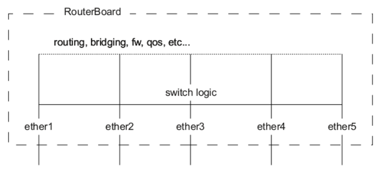
A packet that is received by one of the ports always passes through the switch logic first. Switch logic decides which ports the packet should be going to (most commonly this decision is made based on the destination MAC address of a packet, but there might be other criteria that might be involved based on the packet and the configuration). In most cases the packet will not be visible to RouterOS (only statistics will show that a packet has passed through), this is because the packet was already processed by the switch chip and never reached the CPU.
Though it is possible in certain situations to allow a packet to be processed by the CPU, this is usually called a packet forwarding to the switch CPU port (or the bridge interface in bridge VLAN filtering scenario). This allows the CPU to process the packet and lets the CPU to forward the packet. Passing the packet to the CPU port will give you the opportunity to route packets to different networks, perform traffic control and other software related packet processing actions. To allow a packet to be processed by the CPU, you need to make certain configuration changes depending on your needs and on the device you are using (most commonly passing packets to the CPU are required for VLAN filtering setups). Check the manual page for your specific device:
- CRS1xx/2xx series switches
- CRS3xx, CRS5xx series switches and CCR2116, CCR2216 routers
- non-CRS series switches
Certain bridge and Ethernet port properties are directly related to switch chip settings, changing such properties can trigger a switch chip reset, that will temporarily disable all Ethernet ports that are on the switch chip for the settings to have an effect, this must be taken into account whenever changing properties on production environments. Such properties are DHCP Snooping, IGMP Snooping, VLAN filtering, L2MTU, Flow Control, and others (exact settings that can trigger a switch chip reset depends on the device’s model).
The CRS1xx/2xx series switches support multiple hardware offloaded bridges per switch chip. All other devices support only one hardware offloaded bridge per switch chip. Use the hw=yes/no parameter to select which bridge will use hardware offloading.
Example
Port switching with bridge configuration and enabled hardware offloading since RouterOS v6.41:
/interface bridge
add name=bridge1
/interface bridge port
add bridge=bridge1 interface=ether2 hw=yes
add bridge=bridge1 interface=ether3 hw=yes
add bridge=bridge1 interface=ether4 hw=yes
add bridge=bridge1 interface=ether5 hw=yes
Make sure that hardware offloading is enabled and active by checking the «H» flag:
[admin@MikroTik] /interface bridge port print
Flags: X - disabled, I - inactive, D - dynamic, H - hw-offload
 #     INTERFACE       BRIDGE       HW  PVID PRIORITY  PATH-COST INTERNAL-PATH-COST    HORIZON
 0   H ether2          bridge1      yes    1     0x80         10                 10       none
 1   H ether3          bridge1      yes    1     0x80         10                 10       none
 2   H ether4          bridge1      yes    1     0x80         10                 10       none
 3   H ether5          bridge1      yes    1     0x80         10                 10       none
Port switching in RouterOS v6.41 and newer is done using the bridge configuration. Prior to RouterOS v6.41 port switching was done using the master-port property.
Bridge VLAN Filtering
Bridge VLAN Filtering since RouterOS v6.41 provides VLAN aware Layer2 forwarding and VLAN tag modifications within the bridge. This set of features makes bridge operation more like a traditional Ethernet switch and allows to overcome Spanning Tree compatibility issues compared to the configuration when VLAN interfaces are bridged. Bridge VLAN Filtering configuration is highly recommended to comply with STP (IEEE 802.1D), RSTP (IEEE 802.1W) standards, and is mandatory to enable MSTP (IEEE 802.1s) support in RouterOS.
The main VLAN setting is vlan-filtering which globally controls VLAN-awareness and VLAN tag processing in the bridge. If vlan-filtering=no is configured, the bridge ignores VLAN tags, works in a shared-VLAN-learning (SVL) mode, and cannot modify VLAN tags of packets. Turning on vlan-filtering enables all bridge VLAN related functionality and independent-VLAN-learning (IVL) mode. Besides joining the ports for Layer2 forwarding, the bridge itself is also an interface therefore it has Port VLAN ID (pvid).
Currently, CRS3xx, CRS5xx series switches, CCR2116, CCR2216 routers and RTL8367, 88E6393X, 88E6191X, 88E6190, MT7621 and MT7531 switch chips (since RouterOS v7) are capable of using bridge VLAN filtering and hardware offloading at the same time, other devices will not be able to use the benefits of a built-in switch chip when bridge VLAN filtering is enabled. Other devices should be configured according to the method described in the Basic VLAN switching guide. If an improper configuration method is used, your device can cause throughput issues in your network.
Bridge VLAN table
Bridge VLAN table represents per-VLAN port mapping with an egress VLAN tag action. The tagged ports send out frames with a corresponding VLAN ID tag. The untagged ports remove a VLAN tag before sending out frames. Bridge ports with frame-types set to admit-all or admit-only-untagged-and-priority-tagged will be automatically added as untagged ports for the pvid VLAN.
Sub-menu: /interface bridge vlan
| Property | Description |
|---|---|
| bridge (name; Default: none) | The bridge interface which the respective VLAN entry is intended for. |
| disabled (yes | no; Default: no) | Enables or disables Bridge VLAN entry. |
| tagged (interfaces; Default: none) | Interface list with a VLAN tag adding action in egress. This setting accepts comma-separated values. e.g. tagged=ether1,ether2. |
| untagged (interfaces; Default: none) | Interface list with a VLAN tag removing action in egress. This setting accepts comma-separated values. e.g. untagged=ether3,ether4 |
| vlan-ids (integer 1..4094; Default: 1) | The list of VLAN IDs for certain port configuration. This setting accepts the VLAN ID range as well as comma-separated values. e.g. vlan-ids=100-115,120,122,128-130. |
The vlan-ids parameter can be used to specify a set or range of VLANs, but specifying multiple VLANs in a single bridge VLAN table entry should only be used for ports that are tagged ports. In case multiple VLANs are specified for access ports, then tagged packets might get sent out as untagged packets through the wrong access port, regardless of the PVID value.
Make sure you have added all needed interfaces to the bridge VLAN table when using bridge VLAN filtering. For routing functions to work properly on the same device through ports that use bridge VLAN filtering, you will need to allow access to the bridge interface (this automatically include a switch-cpu port when HW offloaded vlan-filtering is used, e.g. on CRS3xx series switches), this can be done by adding the bridge interface itself to the VLAN table, for tagged traffic you will need to add the bridge interface as a tagged port and create a VLAN interface on the bridge interface. Examples can be found in the inter-VLAN routing and Management port sections.
When allowing access to the CPU, you are allowing access from a certain port to the actual router/switch, this is not always desirable. Make sure you implement proper firewall filter rules to secure your device when access to the CPU is allowed from a certain VLAN ID and port, use firewall filter rules to allow access to only certain services.
Improperly configured bridge VLAN filtering can cause security issues, make sure you fully understand how Bridge VLAN table works before deploying your device into production environments.
Bridge port settings
Each bridge port have multiple VLAN related settings, that can change untagged VLAN membership, VLAN tagging/untagging behavior and packet filtering based on VLAN tag presence.
Sub-menu: /interface bridge port
| Property | Description |
|---|---|
| frame-types (admit-all | admit-only-untagged-and-priority-tagged | admit-only-vlan-tagged; Default: admit-all) | Specifies allowed ingress frame types on a bridge port. This property only has an effect when vlan-filtering is set to yes. |
| ingress-filtering (yes | no; Default: yes) | Enables or disables VLAN ingress filtering, which checks if the ingress port is a member of the received VLAN ID in the bridge VLAN table. Should be used with frame-types to specify if the ingress traffic should be tagged or untagged. This property only has effect when vlan-filtering is set to yes. The setting is enabled by default since RouterOS v7. |
| pvid (integer 1..4094; Default: 1) | Port VLAN ID (pvid) specifies which VLAN the untagged ingress traffic is assigned to. This property only has an effect when vlan-filtering is set to yes. |
| tag-stacking (yes | no; Default: no) | Forces all packets to be treated as untagged packets. Packets on ingress port will be tagged with another VLAN tag regardless if a VLAN tag already exists, packets will be tagged with a VLAN ID that matches the pvid value and will use EtherType that is specified in ether-type. This property only has effect when vlan-filtering is set to yes. |
Bridge host table
Bridge host table allows monitoring learned MAC addresses. When vlan-filtering is enabled, it shows learned VLAN ID as well (enabled independent-VLAN-learning or IVL).
[admin@MikroTik] > /interface bridge host print where !local
Flags: X - disabled, I - invalid, D - dynamic, L - local, E - external
 #       MAC-ADDRESS        VID ON-INTERFACE       BRIDGE
 0   D   CC:2D:E0:E4:B3:AA  300 ether3             bridge1
 1   D   CC:2D:E0:E4:B3:AB  400 ether4             bridge1
VLAN Example — Trunk and Access Ports
Create a bridge with disabled vlan-filtering to avoid losing access to the device before VLANs are completely configured. If you need a management access to the bridge, see the Management access configuration section.
/interface bridge
add name=bridge1 vlan-filtering=no
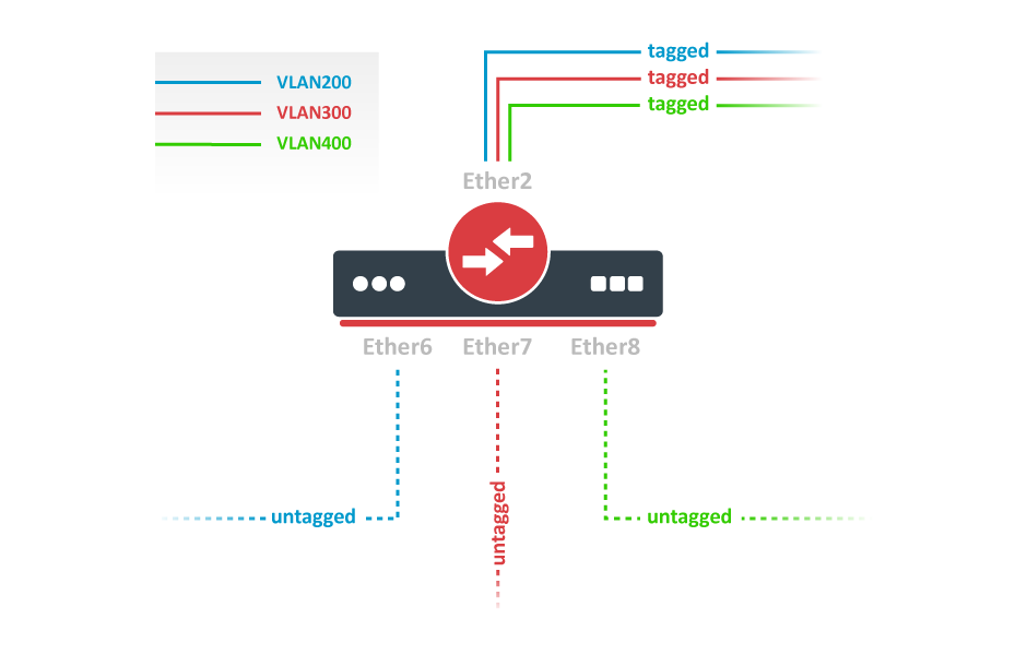
Add bridge ports and specify pvid for access ports to assign their untagged traffic to the intended VLAN. Use frame-types setting to accept only tagged or untagged packets.
/interface bridge port
add bridge=bridge1 interface=ether2 frame-types=admit-only-vlan-tagged
add bridge=bridge1 interface=ether6 pvid=200 frame-types=admit-only-untagged-and-priority-tagged
add bridge=bridge1 interface=ether7 pvid=300 frame-types=admit-only-untagged-and-priority-tagged
add bridge=bridge1 interface=ether8 pvid=400 frame-types=admit-only-untagged-and-priority-tagged
Add Bridge VLAN entries and specify tagged ports in them. Bridge ports with frame-types set to admit-only-untagged-and-priority-tagged will be automatically added as untagged ports for the pvid VLAN.
/interface bridge vlan
add bridge=bridge1 tagged=ether2 vlan-ids=200
add bridge=bridge1 tagged=ether2 vlan-ids=300
add bridge=bridge1 tagged=ether2 vlan-ids=400
In the end, when VLAN configuration is complete, enable Bridge VLAN Filtering.
/interface bridge set bridge1 vlan-filtering=yes
Optional step is to set frame-types=admit-only-vlan-tagged on the bridge interface in order to disable the default untagged VLAN 1 (pvid=1).
/interface bridge set bridge1 frame-types=admit-only-vlan-tagged
VLAN Example — Trunk and Hybrid Ports
Create a bridge with disabled vlan-filtering to avoid losing access to the router before VLANs are completely configured. If you need a management access to the bridge, see the Management access configuration section.
/interface bridge
add name=bridge1 vlan-filtering=no
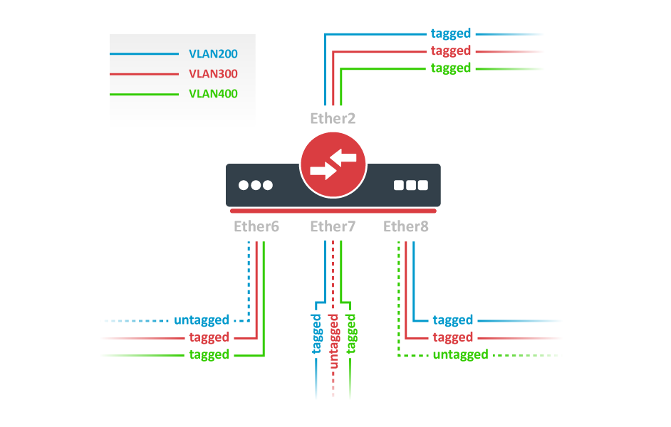
Add bridge ports and specify pvid on hybrid VLAN ports to assign untagged traffic to the intended VLAN. Use frame-types setting to accept only tagged packets on ether2.
/interface bridge port
add bridge=bridge1 interface=ether2 frame-types=admit-only-vlan-tagged
add bridge=bridge1 interface=ether6 pvid=200
add bridge=bridge1 interface=ether7 pvid=300
add bridge=bridge1 interface=ether8 pvid=400
Add Bridge VLAN entries and specify tagged ports in them. In this example egress VLAN tagging is done on ether6,ether7,ether8 ports too, making them into hybrid ports. Bridge ports with frame-types set to admit-all will be automatically added as untagged ports for the pvid VLAN.
/interface bridge vlan
add bridge=bridge1 tagged=ether2,ether7,ether8 vlan-ids=200
add bridge=bridge1 tagged=ether2,ether6,ether8 vlan-ids=300
add bridge=bridge1 tagged=ether2,ether6,ether7 vlan-ids=400
In the end, when VLAN configuration is complete, enable Bridge VLAN Filtering.
/interface bridge set bridge1 vlan-filtering=yes
Optional step is to set frame-types=admit-only-vlan-tagged on the bridge interface in order to disable the default untagged VLAN 1 (pvid=1).
/interface bridge set bridge1 frame-types=admit-only-vlan-tagged
You don’t have to add access ports as untagged ports, because they will be added dynamically as an untagged port with the VLAN ID that is specified in pvid, you can specify just the trunk port as a tagged port. All ports that have the same pvid set will be added as untagged ports in a single entry. You must take into account that the bridge itself is a port and it also has a pvid value, this means that the bridge port also will be added as an untagged port for the ports that have the same pvid. You can circumvent this behavior by either setting different pvid on all ports (even the trunk port and bridge itself), or to use frame-type set to accept-only-vlan-tagged.
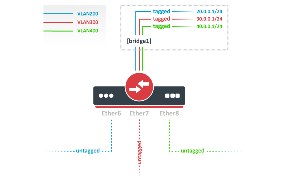
VLAN Example — InterVLAN Routing by Bridge
Create a bridge with disabled vlan-filtering to avoid losing access to the router before VLANs are completely configured. If you need a management access to the bridge, see the Management access configuration section.
/interface bridge
add name=bridge1 vlan-filtering=no
Add bridge ports and specify pvid for VLAN access ports to assign their untagged traffic to the intended VLAN. Use frame-types setting to accept only untagged packets.
/interface bridge port
add bridge=bridge1 interface=ether6 pvid=200 frame-types=admit-only-untagged-and-priority-tagged
add bridge=bridge1 interface=ether7 pvid=300 frame-types=admit-only-untagged-and-priority-tagged
add bridge=bridge1 interface=ether8 pvid=400 frame-types=admit-only-untagged-and-priority-tagged
Add Bridge VLAN entries and specify tagged ports in them. In this example bridge1 interface is the VLAN trunk that will send traffic further to do InterVLAN routing. Bridge ports with frame-types set to admit-only-untagged-and-priority-tagged will be automatically added as untagged ports for the pvid VLAN.
/interface bridge vlan
add bridge=bridge1 tagged=bridge1 vlan-ids=200
add bridge=bridge1 tagged=bridge1 vlan-ids=300
add bridge=bridge1 tagged=bridge1 vlan-ids=400
Configure VLAN interfaces on the bridge1 to allow handling of tagged VLAN traffic at routing level and set IP addresses to ensure routing between VLANs as planned.
/interface vlan
add interface=bridge1 name=VLAN200 vlan-id=200
add interface=bridge1 name=VLAN300 vlan-id=300
add interface=bridge1 name=VLAN400 vlan-id=400

/ip address
add address=20.0.0.1/24 interface=VLAN200
add address=30.0.0.1/24 interface=VLAN300
add address=40.0.0.1/24 interface=VLAN400
In the end, when VLAN configuration is complete, enable Bridge VLAN Filtering:
/interface bridge set bridge1 vlan-filtering=yes
Optional step is to set frame-types=admit-only-vlan-tagged on the bridge interface in order to disable the default untagged VLAN 1 (pvid=1).
/interface bridge set bridge1 frame-types=admit-only-vlan-tagged
Since RouterOS v7, it is possible to route traffic using the L3 HW offloading on certain devices. See more details on L3 Hardware Offloading.
Management access configuration
There are multiple ways to set up management access on a device that uses bridge VLAN filtering. Below are some of the most popular approaches to properly enable access to a router/switch. Start by creating a bridge without VLAN filtering enabled:
/interface bridge
add name=bridge1 vlan-filtering=no
Untagged access without VLAN filtering
In case VLAN filtering will not be used and access with untagged traffic is desired, the only requirement is to create an IP address on the bridge interface.
/ip address
add address=192.168.99.1/24 interface=bridge1
Tagged access without VLAN filtering
In case VLAN filtering will not be used and access with tagged traffic is desired, create a routable VLAN interface on the bridge and add an IP address on the VLAN interface.
/interface vlan
add interface=bridge1 name=MGMT vlan-id=99
/ip address
add address=192.168.99.1/24 interface=MGMT
Tagged access with VLAN filtering
In case VLAN filtering is used and access with tagged traffic is desired, additional steps are required. In this example, VLAN 99 will be used to access the device. A VLAN interface on the bridge must be created and an IP address must be assigned to it.
/interface vlan
add interface=bridge1 name=MGMT vlan-id=99
/ip address
add address=192.168.99.1/24 interface=MGMT
For example, if you want to allow access to the device from ports ether3, ether4, sfp-sfpplus1 using tagged VLAN 99 traffic, then you must add this entry to the VLAN table. Note that the bridge1 interface is also included in the tagged port list:
/interface bridge vlan
add bridge=bridge1 tagged=bridge1,ether3,ether4,sfp-sfpplus1 vlan-ids=99
After that you can enable VLAN filtering:
/interface bridge set bridge1 vlan-filtering=yes
Untagged access with VLAN filtering
In case VLAN filtering is used and access with untagged traffic is desired, the VLAN interface must use the same VLAN ID as the untagged port VLAN ID (pvid). Just like in the previous example, start by creating a VLAN interface on the bridge and add an IP address for the VLAN.
/interface vlan
add interface=bridge1 name=MGMT vlan-id=99
/ip address
add address=192.168.99.1/24 interface=MGMT
For example, untagged ports ether2 and ether3 should be able to communicate with the VLAN 99 interface using untagged traffic. In order to achieve this, these ports should be configured with the pvid that matches the VLAN ID on management VLAN. Note that the bridge1 interface is a tagged port member, you can configure additional tagged ports if necessary (see the previous example).
/interface bridge port
set [find interface=ether2] pvid=99
set [find interface=ether3] pvid=99
/interface bridge vlan
add bridge=bridge1 tagged=bridge1 untagged=ether2,ether3 vlan-ids=99
After that you can enable VLAN filtering:
/interface bridge set bridge1 vlan-filtering=yes
Changing untagged VLAN for the bridge interface
In case VLAN filtering is used, it is possible to change the untagged VLAN ID for the bridge interface using the pvid setting. Note that creating routable VLAN interfaces and allowing tagged traffic on the bridge is a more flexible and generally recommended option.
First, create an IP address on the bridge interface.
/ip address
add address=192.168.99.1/24 interface=bridge1
For example, untagged bridge1 traffic should be able to communicate with untagged ether2 and ether3 ports and tagged sfp-sfpplus1 port in VLAN 99. In order to achieve this, bridge1, ether2, ether3 should be configured with the same pvid and sfp-sfpplus1 added as a tagged member.
/interface bridge
set [find name=bridge1] pvid=99
/interface bridge port
set [find interface=ether2] pvid=99
set [find interface=ether3] pvid=99
/interface bridge vlan
add bridge=bridge1 tagged=sfp-sfpplus1 untagged=bridge1,ether2,ether3 vlan-ids=99
After that you can enable VLAN filtering:
/interface bridge set bridge1 vlan-filtering=yes
If the connection to the router/switch through an IP address is not required, then steps adding an IP address can be skipped since a connection to the router/switch through Layer2 protocols (e.g. MAC-telnet) will be working either way.
VLAN Tunneling (QinQ)
Since RouterOS v6.43 the RouterOS bridge is IEEE 802.1ad compliant and it is possible to filter VLAN IDs based on Service VLAN ID (0x88a8) rather than Customer VLAN ID (0x8100). The same principles can be applied as with IEEE 802.1Q VLAN filtering (the same setup examples can be used). Below is a topology for a common Provider bridge:
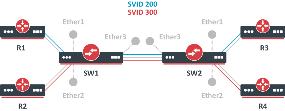
In this example, R1, R2, R3, and R4 might be sending any VLAN tagged traffic by 802.1Q (CVID), but SW1 and SW2 needs isolate traffic between routers in a way that R1 is able to communicate only with R3, and R2 is only able to communicate with R4. To do so, you can tag all ingress traffic with an SVID and only allow these VLANs on certain ports. Start by enabling the service tag 0x88a8, introduced by 802.1ad, on the bridge. Use these commands on SW1 and SW2:
/interface bridge
add name=bridge1 vlan-filtering=no ether-type=0x88a8
In this setup, ether1 and ether2 are going to be access ports (untagged), use the pvid parameter to tag all ingress traffic on each port, use these commands on SW1 and SW2:
/interface bridge port
add interface=ether1 bridge=bridge1 pvid=200
add interface=ether2 bridge=bridge1 pvid=300
add interface=ether3 bridge=bridge1
Specify tagged and untagged ports in the bridge VLAN table, use these commands on SW1 and SW2:
/interface bridge vlan
add bridge=bridge1 tagged=ether3 untagged=ether1 vlan-ids=200
add bridge=bridge1 tagged=ether3 untagged=ether2 vlan-ids=300
When the bridge VLAN table is configured, you can enable bridge VLAN filtering, use these commands on SW1 and SW2:
/interface bridge set bridge1 vlan-filtering=yes
By enabling vlan-filtering you will be filtering out traffic destined to the CPU, before enabling VLAN filtering you should make sure that you set up a Management port.
Note, that if you are using the new EtherType/TPID 0x88a8 (service tag) and you also need a VLAN interface for your Service VLAN, you will also have to apply the use-service-tag parameter on the VLAN interface.
When ether-type=0x8100 is configured, the bridge checks the outer VLAN tag and sees if it is using EtherType 0x8100. If the bridge receives a packet with an outer tag that has a different EtherType, it will mark the packet as untagged. Since RouterOS only checks the outer tag of a packet, it is not possible to filter 802.1Q packets when the 802.1ad protocol is used.
Currently, only CRS3xx, CRS5xx series switches and CCR2116, CCR2216 routers are capable of hardware offloaded VLAN filtering using the Service tag, EtherType/TPID 0x88a8.
Devices with switch chip Marvell-98DX3257 (e.g. CRS354 series) do not support VLAN filtering on 1Gbps Ethernet interfaces for other VLAN types (0x88a8 and 0x9100).
Since RouterOS v6.43 it is possible to forcefully add a new VLAN tag over any existing VLAN tags, this feature can be used to achieve a CVID stacking setup, where a CVID (0x8100) tag is added before an existing CVID tag. This type of setup is very similar to the Provider bridge setup, to achieve the same setup but with multiple CVID tags (CVID stacking) we can use the same topology:
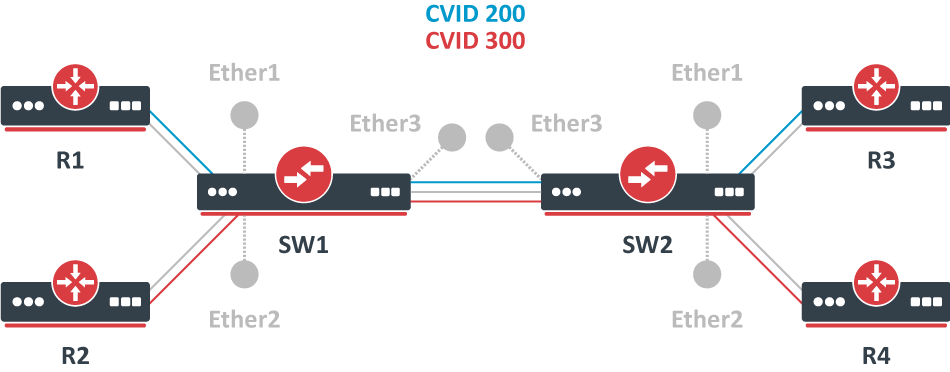
In this example R1, R2, R3, and R4 might be sending any VLAN tagged traffic, it can be 802.1ad, 802.1Q or any other type of traffic, but SW1 and SW2 needs isolate traffic between routers in a way that R1 is able to communicate only with R3, and R2 is only able to communicate with R4. To do so, you can tag all ingress traffic with a new CVID tag and only allow these VLANs on certain ports. Start by selecting the proper EtherType, use these commands on SW1 and SW2:
/interface bridge
add name=bridge1 vlan-filtering=no ether-type=0x8100
In this setup, ether1 and ether2 will ignore any VLAN tags that are present and add a new VLAN tag, use the pvid parameter to tag all ingress traffic on each port and allow tag-stacking on these ports, use these commands on SW1 and SW2:
/interface bridge port
add interface=ether1 bridge=bridge1 pvid=200 tag-stacking=yes
add interface=ether2 bridge=bridge1 pvid=300 tag-stacking=yes
add interface=ether3 bridge=bridge1
Specify tagged and untagged ports in the bridge VLAN table, you only need to specify the VLAN ID of the outer tag, use these commands on SW1 and SW2:
/interface bridge vlan
add bridge=bridge1 tagged=ether3 untagged=ether1 vlan-ids=200
add bridge=bridge1 tagged=ether3 untagged=ether2 vlan-ids=300
When the bridge VLAN table is configured, you can enable bridge VLAN filtering, which is required in order for the pvid parameter to have any effect, use these commands on SW1 and SW2:
/interface bridge set bridge1 vlan-filtering=yes
By enabling vlan-filtering you will be filtering out traffic destined to the CPU, before enabling VLAN filtering you should make sure that you set up a Management port.
Fast Forward
Fast Forward allows forwarding packets faster under special conditions. When Fast Forward is enabled, then the bridge can process packets even faster since it can skip multiple bridge-related checks, including MAC learning. Below you can find a list of conditions that MUST be met in order for Fast Forward to be active:
- Bridge has
fast-forwardset toyes - Bridge has only 2 running ports
- Both bridge ports support Fast Path, Fast Path is active on ports and globally on the bridge
- Bridge Hardware Offloading is disabled
- Bridge VLAN Filtering is disabled
- Bridge DHCP snooping is disabled
unknown-multicast-floodis set toyesunknown-unicast-floodis set toyesbroadcast-floodis set toyes- MAC address for the bridge matches with a MAC address from one of the bridge slave ports
horizonfor both ports is set tonone
Fast Forward disables MAC learning, this is by design to achieve faster packet forwarding. MAC learning prevents traffic from flooding multiple interfaces, but MAC learning is not needed when a packet can only be sent out through just one interface.
Fast Forward is disabled when hardware offloading is enabled. Hardware offloading can achieve full write-speed performance when it is active since it will use the built-in switch chip (if such exists on your device), fast forward uses the CPU to forward packets. When comparing throughput results, you would get such results: Hardware offloading > Fast Forward > Fast Path > Slow Path.
It is possible to check how many packets where processed by Fast Forward:
[admin@MikroTik] /interface bridge settings> pr
              use-ip-firewall: no
     use-ip-firewall-for-vlan: no
    use-ip-firewall-for-pppoe: no
              allow-fast-path: yes
      bridge-fast-path-active: yes
     bridge-fast-path-packets: 0
       bridge-fast-path-bytes: 0
  bridge-fast-forward-packets: 16423
    bridge-fast-forward-bytes: 24864422
If packets are processed by Fast Path, then Fast Forward is not active. Packet count can be used as an indicator of whether Fast Forward is active or not.
Since RouterOS 6.44 it is possible to monitor Fast Forward status, for example:
[admin@MikroTik] /interface bridge monitor bridge1
                  state: enabled
    current-mac-address: B8:69:F4:C9:EE:D7
            root-bridge: yes
         root-bridge-id: 0x8000.B8:69:F4:C9:EE:D7
         root-path-cost: 0
              root-port: none
             port-count: 2
  designated-port-count: 2
           fast-forward: yes
Disabling or enabling fast-forward will temporarily disable all bridge ports for settings to take effect. This must be taken into account whenever changing this property on production environments since it can cause all packets to be temporarily dropped.
IGMP/MLD Snooping
Starting from RouterOS version 6.41, the bridge supports IGMP/MLD snooping. It controls multicast streams and prevents multicast flooding on unnecessary ports. Its settings are placed in the bridge menu and it works independently in every bridge interface. Software-driven implementation works on all devices with RouterOS, but CRS3xx, CRS5xx series switches, CCR2116, CR2216 routers, and 88E6393X, 88E6191X, 88E6190 switch chips also support IGMP/MLD snooping with hardware offloading. See more details on IGMP/MLD snooping manual.
DHCP Snooping and DHCP Option 82
Starting from RouterOS version 6.43, the bridge supports DHCP Snooping and DHCP Option 82. The DHCP Snooping is a Layer2 security feature, that limits unauthorized DHCP servers from providing malicious information to users. In RouterOS, you can specify which bridge ports are trusted (where known DHCP server resides and DHCP messages should be forwarded) and which are untrusted (usually used for access ports, received DHCP server messages will be dropped). The DHCP Option 82 is additional information (Agent Circuit ID and Agent Remote ID) provided by DHCP Snooping enabled devices that allow identifying the device itself and DHCP clients.
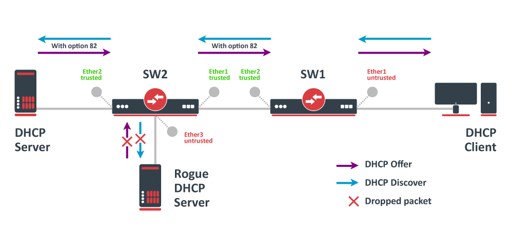
In this example, SW1 and SW2 are DHCP Snooping, and Option 82 enabled devices. First, we need to create a bridge, assign interfaces and mark trusted ports. Use these commands on SW1:
/interface bridge
add name=bridge
/interface bridge port
add bridge=bridge interface=ether1
add bridge=bridge interface=ether2 trusted=yes
For SW2, the configuration will be similar, but we also need to mark ether1 as trusted, because this interface is going to receive DHCP messages with Option 82 already added. You need to mark all ports as trusted if they are going to receive DHCP messages with added Option 82, otherwise these messages will be dropped. Also, we add ether3 to the same bridge and leave this port untrusted, imagine there is an unauthorized (rogue) DHCP server. Use these commands on SW2:
/interface bridge
add name=bridge
/interface bridge port
add bridge=bridge interface=ether1 trusted=yes
add bridge=bridge interface=ether2 trusted=yes
add bridge=bridge interface=ether3
Then we need to enable DHCP Snooping and Option 82. In case your DHCP server does not support DHCP Option 82 or you do not implement any Option 82 related policies, this option can be disabled. Use these commands on SW1 and SW2:
/interface bridge
set [find where name="bridge"] dhcp-snooping=yes add-dhcp-option82=yes
Now both devices will analyze what DHCP messages are received on bridge ports. The SW1 is responsible for adding and removing the DHCP Option 82. The SW2 will limit rogue DHCP server from receiving any discovery messages and drop malicious DHCP server messages from ether3.
Currently, CRS3xx, CRS5xx series switches, CCR2116, CR2216 routers, and 88E6393X, 88E6191X, 88E6190 switch chips fully support hardware offloaded DHCP Snooping and Option 82. For CRS1xx and CRS2xx series switches it is possible to use DHCP Snooping along with VLAN switching, but then you need to make sure that DHCP packets are sent out with the correct VLAN tag using egress ACL rules. Other devices are capable of using DHCP Snooping and Option 82 features along with hardware offloading, but you must make sure that there is no VLAN-related configuration applied on the device, otherwise, DHCP Snooping and Option 82 might not work properly. See the Bridge Hardware Offloading section with supported features.
For CRS3xx, CRS5xx series switches and CCR2116, CR2216 routers DHCP snooping will not work when hardware offloading bonding interfaces are created.
Controller Bridge and Port Extender
Controller Bridge (CB) and Port Extender (PE) is an IEEE 802.1BR standard implementation in RouterOS for CRS3xx, CRS5xx series switches and CCR2116, CCR2216 routers. It allows virtually extending the CB ports with a PE device and managing these extended interfaces from a single controlling device. Such configuration provides a simplified network topology, flexibility, increased port density, and ease of manageability. See more details on Controller Bridge and Port Extender manual.
Bridge Firewall
The bridge firewall implements packet filtering and thereby provides security functions that are used to manage data flow to, from, and through the bridge.
Packet flow diagram shows how packets are processed through the router. It is possible to force bridge traffic to go through /ip firewall filter rules (see the bridge settings).
There are two bridge firewall tables:
- filter — bridge firewall with three predefined chains:
- input — filters packets, where the destination is the bridge (including those packets that will be routed, as they are destined to the bridge MAC address anyway)
- output — filters packets, which come from the bridge (including those packets that has been routed normally)
- forward — filters packets, which are to be bridged (note: this chain is not applied to the packets that should be routed through the router, just to those that are traversing between the ports of the same bridge)
- nat — bridge network address translation provides ways for changing source/destination MAC addresses of the packets traversing a bridge. Has two built-in chains:
- srcnat — used for «hiding» a host or a network behind a different MAC address. This chain is applied to the packets leaving the router through a bridged interface
- dstnat — used for redirecting some packets to other destinations
You can put packet marks in bridge firewall (filter and NAT), which are the same as the packet marks in IP firewall configured by '/ip firewall mangle'. In this way, packet marks put by bridge firewall can be used in ‘IP firewall’, and vice versa.
General bridge firewall properties are described in this section. Some parameters that differ between nat and filter rules are described in further sections.
Sub-menu: /interface bridge filter, /interface bridge nat
| Property | Description |
|---|---|
| 802.3-sap (integer; Default: ) | DSAP (Destination Service Access Point) and SSAP (Source Service Access Point) are 2 one-byte fields, which identify the network protocol entities which use the link-layer service. These bytes are always equal. Two hexadecimal digits may be specified here to match an SAP byte. |
| 802.3-type (integer; Default: ) | Ethernet protocol type, placed after the IEEE 802.2 frame header. Works only if 802.3-sap is 0xAA (SNAP — Sub-Network Attachment Point header). For example, AppleTalk can be indicated by the SAP code of 0xAA followed by a SNAP type code of 0x809B. |
| action (accept | drop | jump | log | mark-packet | passthrough | return | set-priority; Default: ) | Action to take if the packet is matched by the rule:
|
| arp-dst-address (IP address; Default: ) | ARP destination IP address. |
| arp-dst-mac-address (MAC address; Default: ) | ARP destination MAC address. |
| arp-gratuitous (yes | no; Default: ) | Matches ARP gratuitous packets. |
| arp-hardware-type (integer; Default: 1) | ARP hardware type. This is normally Ethernet (Type 1). |
| arp-opcode (arp-nak | drarp-error | drarp-reply | drarp-request | inarp-reply | inarp-request | reply | reply-reverse | request | request-reverse; Default: ) | ARP opcode (packet type)
|
| arp-packet-type (integer 0..65535 | hex 0x0000-0xffff; Default: ) | ARP Packet Type. |
| arp-src-address (IP address; Default: ) | ARP source IP address. |
| arp-src-mac-address (MAC addres; Default: ) | ARP source MAC address. |
| chain (text; Default: ) | Bridge firewall chain, which the filter is functioning in (either a built-in one, or a user-defined one). |
| dst-address (IP address; Default: ) | Destination IP address (only if MAC protocol is set to IP). |
| dst-address6 (IPv6 address; Default: ) | Destination IPv6 address (only if MAC protocol is set to IPv6). |
| dst-mac-address (MAC address; Default: ) | Destination MAC address. |
| dst-port (integer 0..65535; Default: ) | Destination port number or range (only for TCP or UDP protocols). |
| in-bridge (name; Default: ) | Bridge interface through which the packet is coming in. |
| in-bridge-list (name; Default: ) | Set of bridge interfaces defined in interface list. Works the same as in-bridge. |
| in-interface (name; Default: ) | Physical interface (i.e., bridge port) through which the packet is coming in. |
| in-interface-list (name; Default: ) | Set of interfaces defined in interface list. Works the same as in-interface. |
| ingress-priority (integer 0..63; Default: ) | Matches the priority of an ingress packet. Priority may be derived from VLAN, WMM, DSCP or MPLS EXP bit. read more |
| ip-protocol (dccp | ddp | egp | encap | etherip | ggp | gre | hmp | icmp | icmpv6 | idpr-cmtp | igmp | ipencap | ipip | ipsec-ah | ipsec-esp | ipv6 | ipv6-frag | ipv6-nonxt | ipv6-opts | ipv6-route | iso-tp4 | l2tp | ospf | pim | pup | rdp | rspf | rsvp | sctp | st | tcp | udp | udp-lite | vmtp | vrrp | xns-idp | xtp; Default: ) | IP protocol (only if MAC protocol is set to IPv4)
|
| jump-target (name; Default: ) | If action=jump specified, then specifies the user-defined firewall chain to process the packet. |
| limit (integer/time,integer; Default: ) | Restricts packet match rate to a given limit.
|
| log (yes | no; Default: no) | Add a message to the system log containing the following data: in-interface, out-interface, src-mac, dst-mac, eth-protocol, ip-protocol, src-ip:port->dst-ip:port, and length of the packet. |
| log-prefix (text; Default: ) | Defines the prefix to be printed before the logging information. |
| mac-protocol (802.2 | arp | homeplug-av | ip | ipv6 | ipx | length | lldp | loop-protect | mpls-multicast | mpls-unicast | packing-compr | packing-simple | pppoe | pppoe-discovery | rarp | service-vlan | vlan | integer 0..65535 | hex 0x0000-0xffff; Default: ) | Ethernet payload type (MAC-level protocol). To match protocol type for VLAN encapsulated frames (0x8100 or 0x88a8), a vlan-encap property should be used.
|
| new-packet-mark (string; Default: ) | Sets a new packet-mark value. |
| new-priority (integer | from-ingress; Default: ) | Sets a new priority for a packet. This can be the VLAN, WMM or MPLS EXP priority Read more. This property can also be used to set an internal priori |
| out-bridge (name; Default: ) | Outgoing bridge interface. |
| out-bridge-list (name; Default: ) | Set of bridge interfaces defined in interface list. Works the same as out-bridge. |
| out-interface (name; Default: ) | Interface that the packet is leaving the bridge through. |
| out-interface-list (name; Default: ) | Set of interfaces defined in interface list. Works the same as out-interface. |
| packet-mark (name; Default: ) | Match packets with a certain packet mark. |
| packet-type (broadcast | host | multicast | other-host; Default: ) | MAC frame type:
|
| src-address (IP address; Default: ) | Source IP address (only if MAC protocol is set to IPv4). |
| src-address6 (IPv6 address; Default: ) | Source IPv6 address (only if MAC protocol is set to IPv6). |
| src-mac-address (MAC address; Default: ) | Source MAC address. |
| src-port (integer 0..65535; Default: ) | Source port number or range (only for TCP or UDP protocols). |
| stp-flags (topology-change | topology-change-ack; Default: ) | The BPDU (Bridge Protocol Data Unit) flags. Bridge exchange configuration messages named BPDU periodically for preventing loops
|
| stp-forward-delay (integer 0..65535; Default: ) | Forward delay timer. |
| stp-hello-time (integer 0..65535; Default: ) | STP hello packets time. |
| stp-max-age (integer 0..65535; Default: ) | Maximal STP message age. |
| stp-msg-age (integer 0..65535; Default: ) | STP message age. |
| stp-port (integer 0..65535; Default: ) | STP port identifier. |
| stp-root-address (MAC address; Default: ) | Root bridge MAC address. |
| stp-root-cost (integer 0..65535; Default: ) | Root bridge cost. |
| stp-root-priority (integer 0..65535; Default: ) | Root bridge priority. |
| stp-sender-address (MAC address; Default: ) | STP message sender MAC address. |
| stp-sender-priority (integer 0..65535; Default: ) | STP sender priority. |
| stp-type (config | tcn; Default: ) | The BPDU type:
|
| tls-host (string; Default: ) | Allows matching https traffic based on TLS SNI hostname. Accepts GLOB syntax for wildcard matching. Note that matcher will not be able to match hostname if the TLS handshake frame is fragmented into multiple TCP segments (packets). |
| vlan-encap (802.2 | arp | ip | ipv6 | ipx | length | mpls-multicast | mpls-unicast | pppoe | pppoe-discovery | rarp | vlan | integer 0..65535 | hex 0x0000-0xffff; Default: ) | Matches the MAC protocol type encapsulated in the VLAN frame. |
| vlan-id (integer 0..4095; Default: ) | Matches the VLAN identifier field. |
| vlan-priority (integer 0..7; Default: ) | Matches the VLAN priority (priority code point) |
Footnotes:
- STP matchers are only valid if the destination MAC address is
01:80:C2:00:00:00/FF:FF:FF:FF:FF:FF(Bridge Group address), also STP should be enabled.
- ARP matchers are only valid if mac-protocol is
arporrarp
- VLAN matchers are only valid for
0x8100or0x88a8ethernet protocols
- IP or IPv6 related matchers are only valid if mac-protocol is either set to
iporipv6
- 802.3 matchers are only consulted if the actual frame is compliant with IEEE 802.2 and IEEE 802.3 standards. These matchers are ignored for other packets.
Bridge Packet Filter
This section describes specific bridge filter options.
Sub-menu: /interface bridge filter
| Property | Description |
|---|---|
| action (accept | drop | jump | log | mark-packet | passthrough | return | set-priority; Default: accept) | Action to take if the packet is matched by the rule:
|
Bridge NAT
This section describes specific bridge NAT options.
Sub-menu: /interface bridge nat
| Property | Description |
|---|---|
| action (accept | drop | jump | mark-packet | redirect | set-priority | arp-reply | dst-nat | log | passthrough | return | src-nat; Default: accept) | Action to take if the packet is matched by the rule:
|
| to-arp-reply-mac-address (MAC address; Default: ) | Source MAC address to put in Ethernet frame and ARP payload, when action=arp-reply is selected |
| to-dst-mac-address (MAC address; Default: ) | Destination MAC address to put in Ethernet frames, when action=dst-nat is selected |
| to-src-mac-address (MAC address; Default: ) | Source MAC address to put in Ethernet frames, when action=src-nat is selected |
See also
- CRS1xx/2xx series switches
- CRS3xx, CRS5xx series switches, and CCR2116, CCR2216 routers
- Switch chip features
- MTU on RouterBOARD
- Layer2 misconfiguration
- Bridge VLAN Table
- Wireless VLAN Trunk
- VLANs on Wireless
![]()
Applies to RouterOS: v3, v4+
Summary
Sub-menu: /interface bridge
Standards: IEEE 802.1D , IEEE 802.1Q
Ethernet-like networks (Ethernet, Ethernet over IP, IEEE 802.11 in ap-bridge or bridge mode, WDS, VLAN) can be connected together using MAC bridges. The bridge feature allows the interconnection of hosts connected to separate LANs (using EoIP, geographically distributed networks can be bridged as well if any kind of IP network interconnection exists between them) as if they were attached to a single LAN. As bridges are transparent, they do not appear in traceroute list, and no utility can make a distinction between a host working in one LAN and a host working in another LAN if these LANs are bridged (depending on the way the LANs are interconnected, latency and data rate between hosts may vary).
Network loops may emerge (intentionally or not) in complex topologies. Without any special treatment, loops would prevent network from functioning normally, as they would lead to avalanche-like packet multiplication. Each bridge runs an algorithm which calculates how the loop can be prevented. STP and RSTP allows bridges to communicate with each other, so they can negotiate a loop free topology. All other alternative connections that would otherwise form loops, are put to standby, so that should the main connection fail, another connection could take its place. This algorithm exchanges configuration messages (BPDU — Bridge Protocol Data Unit) periodically, so that all bridges are updated with the newest information about changes in network topology. (R)STP selects a root bridge which is responsible for network reconfiguration, such as blocking and opening ports on other bridges. The root bridge is the bridge with the lowest bridge ID.
Bridge Interface Setup
Sub-menu: /interface bridge
To combine a number of networks into one bridge, a bridge interface should be created (later, all the desired interfaces should be set up as its ports). One MAC address from slave (secondary) ports will be assigned to the bridge interface, the MAC address will be chosen automatically, depending on «port-number», and it can change after a reboot. To avoid unwanted MAC address changes, it is recommended to disable «auto-mac», and to manually specify MAC by using «admin-mac».
Properties
| Property | Description |
|---|---|
| add-dhcp-option82 (yes | no; Default: no) | Whether to add DHCP Option-82 information (Agent Remote ID and Agent Circuit ID) to DHCP packets. Can be used together with Option-82 capable DHCP server to assign IP addresses and implement policies. This property only has effect when dhcp-snooping is set to yes. |
| admin-mac (MAC address; Default: none) | Static MAC address of the bridge. This property only has effect when auto-mac is set to no. |
| ageing-time (time; Default: 00:05:00) | How long a host’s information will be kept in the bridge database. |
| arp (disabled | enabled | proxy-arp | reply-only; Default: enabled) | Address Resolution Protocol setting
|
| arp-timeout (auto | integer; Default: auto) | ARP timeout is time how long ARP record is kept in ARP table after no packets are received from IP. Value auto equals to the value of arp-timeout in IP/Settings, default is 30s. |
| auto-mac (yes | no; Default: yes) | Automatically select one MAC address of bridge ports as a bridge MAC address, bridge MAC will be chosen from the first added bridge port. After a device reboot, the bridge MAC can change depending on the port-number. |
| comment (string; Default: ) | Short description of the interface. |
| dhcp-snooping (yes | no; Default: no) | Enables or disables DHCP Snooping on the bridge. |
| disabled (yes | no; Default: no) | Changes whether the bridge is disabled. |
| ether-type (0x9100 | 0x8100 | 0x88a8; Default: 0x8100) | Changes the EtherType, which will be used to determine if a packet has a VLAN tag. Packets that have a matching EtherType are considered as tagged packets. This property only has effect when vlan-filtering is set to yes. |
| fast-forward (yes | no; Default: yes) | Special and faster case of FastPath which works only on bridges with 2 interfaces (enabled by default only for new bridges). More details can be found in the Fast Forward section. |
| forward-delay (time; Default: 00:00:15) | Time which is spent during the initialization phase of the bridge interface (i.e., after router startup or enabling the interface) in listening/learning state before the bridge will start functioning normally. |
| frame-types (admit-all | admit-only-untagged-and-priority-tagged | admit-only-vlan-tagged; Default: admit-all) | Specifies allowed frame types on a bridge port. This property only has effect when vlan-filtering is set to yes. |
| igmp-snooping (yes | no; Default: no) | Enables multicast group and port learning to prevent multicast traffic from flooding all interfaces in a bridge. |
| igmp-version (2 | 3; Default: 2) | Selects the IGMP version in which IGMP general membership queries will be generated. This property only has effect when igmp-snooping is set to yes. |
| ingress-filtering (yes | no; Default: no) | Enables or disables VLAN ingress filtering, which checks if the ingress port is a member of the received VLAN ID in the bridge VLAN table. By default, VLANs that don’t exist in the bridge VLAN table are dropped before they are sent out (egress), but this property allows you to drop the packets when they are received (ingress). Should be used with frame-types to specify if the ingress traffic should be tagged or untagged. This property only has effect when vlan-filtering is set to yes. |
| l2mtu (read-only; Default: ) | L2MTU indicates the maximum size of the frame without MAC header that can be sent by this interface. The L2MTU value will be automatically set by the bridge and it will use the lowest L2MTU value of any associated bridge port. This value cannot be manually changed. |
| last-member-interval (time; Default: 1s) | If a port has fast-leave set to no and a bridge port receives a IGMP Leave message, then a IGMP Snooping enabled bridge will send a IGMP query to make sure that no devices has subscribed to a certain multicast stream on a bridge port. If a IGMP Snooping enabled bridge does not receive a IGMP membership report after amount of last-member-interval, then the bridge considers that no one has subscribed to a certain multicast stream and can stop forwarding it. This property only has effect when igmp-snooping is set to yes. |
| last-member-query-count (integer: 0..4294967295; Default: 2) | How many times should last-member-interval pass until a IGMP Snooping bridge will stop forwarding a certain multicast stream. This property only has effect when igmp-snooping is set to yes. |
| max-hops (integer: 6..40; Default: 20) | Bridge count which BPDU can pass in a MSTP enabled network in the same region before BPDU is being ignored. This property only has effect when protocol-mode is set to mstp. |
| max-message-age (time: 6s..40s; Default: 00:00:20) | Changes the Max Age value in BPDU packets, which is transmitted by the root bridge. A root bridge sends a BPDUs with Max Age set to max-message-age value and a Message Age of 0. Every sequential bridge will increment the Message Age before sending their BPDUs. Once a bridge receives a BPDU where Message Age is equal or greater than Max Age, the BPDU is ignored. This property only has effect when protocol-mode is set to stp or rstp. |
| membership-interval (time; Default: 4m20s) | Amount of time after an entry in the Multicast Database (MDB) is removed if a IGMP membership report is not received on a certain port. This property only has effect when igmp-snooping is set to yes. |
| mld-version (1 | 2; Default: 1) | Selects the MLD version. Version 2 adds support for source-specific multicast. This property only has effect when RouterOS IPv6 package is enabled and igmp-snooping is set to yes. |
| mtu (integer; Default: auto) | Maximum transmission unit, by default, the bridge will set MTU automatically and it will use the lowest MTU value of any associated bridge port. The default bridge MTU value without any bridge ports added is 1500. The MTU value can be set manually, but it cannot exceed the bridge L2MTU or the lowest bridge port L2MTU. If a new bridge port is added with L2MTU which is smaller than the actual-mtu of the bridge (set by the mtu property), then manually set value will be ignored and the bridge will act as if mtu=auto is set. |
| multicast-querier (yes | no; Default: no) | Multicast querier generates IGMP general membership queries to which all IGMP capable devices respond with an IGMP membership report, usually a PIM (multicast) router or IGMP proxy generates these queries. When RouterOS IPv6 package is enabled, the bridge will also generate MLD general membership queries. By using this property you can make an IGMP Snooping enabled bridge to generate IGMP/MLD general membership queries. This property should be used whenever there is no active querier (PIM router or IGMP proxy) in a Layer2 network. Without a multicast querier in a Layer2 network, the Multicast Database (MDB) is not being updated and IGMP Snooping will not function properly. Only untagged IGMP/MLD general membership queries are generated. This property only has an effect when igmp-snooping is set to yes. Additionally, the igmp-snooping should be disabled/enabled after changing multicast-querier property. |
| multicast-router (disabled | permanent | temporary-query; Default: temporary-query) | Changes the state of a bridge itself if IGMP membership reports are going to be forwarded to it. This property can be used to forward IGMP membership reports to the bridge for statistics or to analyse them.
|
| name (text; Default: bridgeN) | Name of the bridge interface |
| priority (integer: 0..65535 decimal format or 0x0000-0xffff hex format; Default: 32768 / 0x8000) | Bridge priority, used by STP to determine root bridge, used by MSTP to determine CIST and IST regional root bridge. This property has no effect when protocol-mode is set to none. |
| protocol-mode (none | rstp | stp | mstp; Default: rstp) | Select Spanning tree protocol (STP) or Rapid spanning tree protocol (RSTP) to ensure a loop-free topology for any bridged LAN. RSTP provides for faster spanning tree convergence after a topology change. Select MSTP to ensure loop-free topology across multiple VLANs. Since RouterOS v6.43 it is possible to forward Reserved MAC addresses that are in 01:80:C2:00:00:0X range, this can be done by setting the protocol-mode to none. |
| pvid (integer: 1..4094; Default: 1) | Port VLAN ID (pvid) specifies which VLAN the untagged ingress traffic is assigned to. It applies e.g. to frames sent from bridge IP and destined to a bridge port. This property only has effect when vlan-filtering is set to yes. |
| querier-interval (time; Default: 4m15s) | Used to change the interval how often a bridge checks if it is the active multicast querier. This property only has effect when igmp-snooping and multicast-querier is set to yes. |
| query-interval (time; Default: 2m5s) | Used to change the interval how often IGMP general membership queries are sent out. This property only has effect when igmp-snooping and multicast-querier is set to yes. |
| query-response-interval (time; Default: 10s) | Interval in which a IGMP capable device must reply to a IGMP query with a IGMP membership report. This property only has effect when igmp-snooping and multicast-querier is set to yes. |
| region-name (text; Default: ) | MSTP region name. This property only has effect when protocol-mode is set to mstp. |
| region-revision (integer: 0..65535; Default: 0) | MSTP configuration revision number. This property only has effect when protocol-mode is set to mstp. |
| startup-query-count (integer: 0..4294967295; Default: 2) | Specifies how many times must startup-query-interval pass until the bridge starts sending out IGMP general membership queries periodically. This property only has effect when igmp-snooping and multicast-querier is set to yes. |
| startup-query-interval (time; Default: 31s250ms) | Used to change the amount of time after a bridge starts sending out IGMP general membership queries after the bridge is enabled. This property only has effect when igmp-snooping and multicast-querier is set to yes. |
| transmit-hold-count (integer: 1..10; Default: 6) | The Transmit Hold Count used by the Port Transmit state machine to limit transmission rate. |
| vlan-filtering (yes | no; Default: no) | Globally enables or disables VLAN functionality for bridge. |
![]()
Warning: Changing certain properties can cause the bridge to temporarily disable all ports. This must be taken into account whenever changing such properties on production environments since it can cause all packets to be temporarily dropped. Such properties include vlan-filtering, protocol-mode, igmp-snooping, fast-forward and others.
Example
To add and enable a bridge interface that will forward all the protocols:
[admin@MikroTik] /interface bridge> add
[admin@MikroTik] /interface bridge> print
Flags: X - disabled, R - running
 0  R name="bridge1" mtu=1500 l2mtu=65535 arp=enabled
      mac-address=00:00:00:00:00:00 protocol-mode=none priority=0x8000
      auto-mac=yes admin-mac=00:00:00:00:00:00 max-message-age=20s
      forward-delay=15s transmit-hold-count=6 ageing-time=5m
[admin@MikroTik] /interface bridge>
Spanning Tree Protocol
RouterOS bridge interfaces are capable of running Spanning Tree Protocol to ensure a loop-free and redundant topology. For small networks with just 2 bridges STP does not bring much benefits, but for larger networks properly configured STP is very crucial, leaving STP related values to default may result in completely unreachable network in case of a even single bridge failure. To achieve a proper loop-free and redundant topology, it is necessary to properly set bridge priorities, port path costs and port priorities.
![]()
Warning: In RouterOS it is possible to set any value for bridge priority between 0 and 65535, the IEEE 802.1W standard states that the bridge priority must be in steps of 4096. This can cause incompatibility issues between devices that does not support such values. To avoid compatibility issues, it is recommended to use only these priorities: 0, 4096, 8192, 12288, 16384, 20480, 24576, 28672, 32768, 36864, 40960, 45056, 49152, 53248, 57344, 61440
STP has multiple variants, currently RouterOS supports STP, RSTP and MSTP. Depending on needs, either one of them can be used, some devices are able to run some of these protocols using hardware offloading, detailed information about which device support it can be found in the Hardware Offloading section. STP is considered to be outdated and slow, it has been almost entirely replaced in all network topologies by RSTP, which is backwards compatible with STP. For network topologies that depend on VLANs, it is recommended to use MSTP since it is a VLAN aware protocol and gives the ability to do load balancing per VLAN groups. There are a lot of considerations that should be made when designing a STP enabled network, more detailed case studies can be found in the Spanning Tree Protocol section. In RouterOS the protocol-mode property controls the used STP variant.
![]()
Note: By the IEEE 802.1ad standard the BPDUs from bridges that comply with IEEE 802.1Q are not compatible with IEEE 802.1ad bridges, this means that the same bridge VLAN protocol should be used across all bridges in a single Layer2 domain, otherwise (R/M)STP will not function properly.
Per port STP
There might be certain situations where you want to limit STP functionality on a single or multiple ports. Below you can find some examples for different use cases.
![]()
Warning: Be careful when changing the default (R/M)STP functionality, make sure you understand the working principles of STP and BPDUs. Misconfigured (R/M)STP can cause unexpected behaviour.
- Don’t send out BPDUs from a certain port
/interface bridge
add name=bridge1
/interface bridge port
add bridge=bridge1 interface=ether1
add bridge=bridge1 interface=ether2
add bridge=bridge1 interface=ether3
/interface bridge filter
add action=drop chain=output dst-mac-address=01:80:C2:00:00:00/FF:FF:FF:FF:FF:FF out-interface=ether1
In this example BPDUs will not be sent out through ether1. In case the bridge is the root bridge, then loop detection will not work on this port. If another bridge is connected to ether1, then the other bridge will not receive any BPDUs and therefore might become as a second root bridge. You might want to consider blocking received BPDUs as well.
- Dropping received BPDUs on a certain port can be done on some switch chips using ACL rules, but the Bridge Filter Input rules cannot do it if bridge has STP/RSTP/MSTP enabled because then received BPDUs have special processing in the bridge.
On CRS3xx:
/interface ethernet switch rule
add dst-mac-address=01:80:C2:00:00:00/FF:FF:FF:FF:FF:FF new-dst-ports="" ports=ether1 switch=switch1
Or on CRS1xx/CRS2xx with Access Control List (ACL) support:
/interface ethernet switch acl
add action=drop mac-dst-address=01:80:C2:00:00:00 src-ports=ether1
In this example all received BPDUs on ether1 are dropped. This will prevent other bridges on that port becoming a root bridge.
![]()
Warning: If you intend to drop received BPDUs on a port, then make sure to prevent BPDUs from being sent out from the interface that this port is connected to. A root bridge always sends out BPDUs and under normal conditions is waiting for a more superior BPDU (from a bridge with a lower bridge ID), but the bridge must temporarily disable the new root-port when transitioning from a root bridge to designated bridge. If you have blocked BPDUs only on one side, then a port will flap continuously.
- Don’t allow BPDUs on a port
/interface bridge
add name=bridge1
/interface bridge port
add bridge=bridge1 interface=ether1 bpdu-guard=yes
add bridge=bridge1 interface=ether2
add bridge=bridge1 interface=ether3
In this example if ether1 receives a BPDU, it will block the port and will require you to manually re-enable it.
Bridge Settings
Sub-menu: /interface bridge settings
| Property | Description |
|---|---|
| use-ip-firewall (yes | no; Default: no) | Force bridged traffic to also be processed by prerouting, forward and postrouting sections of IP routing ( Packet Flow). This does not apply to routed traffic. This property is required in case you want to assign Simple Queues or global Queue Tree to traffic in a bridge. Property use-ip-firewall-for-vlan is required in case bridge vlan-filtering is used. |
| use-ip-firewall-for-pppoe (yes | no; Default: no) | Send bridged un-encrypted PPPoE traffic to also be processed by IP/Firewall. This property only has effect when use-ip-firewall is set to yes. This property is required in case you want to assign Simple Queues or global Queue Tree to PPPoE traffic in a bridge. |
| use-ip-firewall-for-vlan (yes | no; Default: no) | Send bridged VLAN traffic to also be processed by IP/Firewall. This property only has effect when use-ip-firewall is set to yes. This property is required in case you want to assign Simple Queues or global Queue Tree to VLAN traffic in a bridge. |
| allow-fast-path (yes | no; Default: yes) | Whether to enable a bridge FastPath globally. |
| bridge-fast-path-active (yes | no; Default: ) | Shows whether a bridge FastPath is active globally, FastPatch status per bridge interface is not displayed. |
| bridge-fast-path-packets (integer; Default: ) | Shows packet count forwarded by Bridge FastPath. |
| bridge-fast-path-bytes (integer; Default: ) | Shows byte count forwarded by Bridge Fast Path. |
| bridge-fast-forward-packets (integer; Default: ) | Shows packet count forwarded by Bridge Fast Forward. |
| bridge-fast-forward-bytes (integer; Default: ) | Shows byte count forwarded by Bridge Fast Forward. |
![]()
Note: In case you want to assign Simple Queues (Simple QoS) or global Queue Trees to traffic that is being forwarded by a bridge, then you need to enable the use-ip-firewall property. Without using this property the bridge traffic will never reach the postrouting chain, Simple Queues and global Queue Trees are working in the postrouting chain. To assign Simple Queues or global Queue Trees for VLAN or PPPoE traffic in a bridge you should enable appropriate properties as well.
Port Settings
Sub-menu: /interface bridge port
Port submenu is used to enslave interfaces in a particular bridge interface.
| Property | Description |
|---|---|
| auto-isolate (yes | no; Default: no) | When enabled, prevents a port moving from discarding into forwarding state if no BPDUs are received from the neighboring bridge. The port will change into a forwarding state only when a BPDU is received. This property only has an effect when protocol-mode is set to rstp or mstp and edge is set to no. |
| bpdu-guard (yes | no; Default: no) | Enables or disables BPDU Guard feature on a port. This feature puts the port in a disabled role if it receives a BPDU and requires the port to be manually disabled and enabled if a BPDU was received. Should be used to prevent a bridge from BPDU related attacks. This property has no effect when protocol-mode is set to none. |
| bridge (name; Default: none) | The bridge interface the respective interface is grouped in. |
| broadcast-flood (yes | no; Default: yes) | When enabled, bridge floods broadcast traffic to all bridge egress ports. When disabled, drops broadcast traffic on egress ports. Can be used to filter all broadcast traffic on an egress port. Broadcast traffic is considered as traffic that uses FF:FF:FF:FF:FF:FF as destination MAC address, such traffic is crucial for many protocols such as DHCP, ARP, NDP, BOOTP (Netinstall) and others. This option does not limit traffic flood to the CPU. |
| edge (auto | no | no-discover | yes | yes-discover; Default: auto) | Set port as edge port or non-edge port, or enable edge discovery. Edge ports are connected to a LAN that has no other bridges attached. An edge port will skip the learning and the listening states in STP and will transition directly to the forwarding state, this reduces the STP initialization time. If the port is configured to discover edge port then as soon as the bridge detects a BPDU coming to an edge port, the port becomes a non-edge port. This property has no effect when protocol-mode is set to none.
|
| external-fdb (auto | no | yes; Default: auto) | Whether to use wireless registration table to speed up bridge host learning. If there are no Wireless interfaces in a bridge, then setting external-fdb to yes will disable MAC learning and the bridge will act as a hub (disables hardware offloading). Replaced with learn parameter in RouterOS v6.42 |
| fast-leave (yes | no; Default: no) | Enables IGMP Fast leave feature on the port. Bridge will stop forwarding traffic to a bridge port whenever a IGMP Leave message is received for appropriate multicast stream. This property only has effect when igmp-snooping is set to yes. |
| frame-types (admit-all | admit-only-untagged-and-priority-tagged | admit-only-vlan-tagged; Default: admit-all) | Specifies allowed ingress frame types on a bridge port. This property only has effect when vlan-filtering is set to yes. |
| ingress-filtering (yes | no; Default: no) | Enables or disables VLAN ingress filtering, which checks if the ingress port is a member of the received VLAN ID in the bridge VLAN table. Should be used with frame-types to specify if the ingress traffic should be tagged or untagged. This property only has effect when vlan-filtering is set to yes. |
| learn (auto | no | yes; Default: auto) | Changes MAC learning behaviour on a bridge port
|
| multicast-router (disabled | permanent | temporary-query; Default: temporary-query) | Changes the state of a bridge port whether IGMP membership reports are going to be forwarded to this port. By default IGMP membership reports (most importantly IGMP Join messages) are only forwarded to ports that have a multicast router or a IGMP Snooping enabled bridge connected to. Without at least one port marked as a multicast-router IPTV might not work properly, it can be either detected automatically or forced manually.
You can improve security by forcing ports that have IPTV boxes connected to never become ports marked as |
| horizon (integer 0..429496729; Default: none) | Use split horizon bridging to prevent bridging loops. Set the same value for group of ports, to prevent them from sending data to ports with the same horizon value. Split horizon is a software feature that disables hardware offloading. Read more about Bridge split horizon. |
| internal-path-cost (integer: 0..4294967295; Default: 10) | Path cost to the interface for MSTI0 inside a region. This property only has effect when protocol-mode is set to mstp. |
| interface (name; Default: none) | Name of the interface. |
| path-cost (integer: 0..4294967295; Default: 10) | Path cost to the interface, used by STP to determine the «best» path, used by MSTP to determine «best» path between regions. This property has no effect when protocol-mode is set to none. |
| point-to-point (auto | yes | no; Default: auto) | Specifies if a bridge port is connected to a bridge using a point-to-point link for faster convergence in case of failure. By setting this property to yes, you are forcing the link to be a point-to-point link, which will skip the checking mechanism, which detects and waits BPDUs from other devices from this single link, by setting this property to no, you are expecting that a link can receive BPDUs from multiple devices. By setting the property to yes, you are significantly improving (R/M)STP convergence time. In general, you should only set this property to no if it is possible that another device can be connected between a link, this is mostly relevant to Wireless mediums and Ethernet hubs. If the Ethernet link is full-duplex, auto enables point-to-point functionality. And this property has no effect when protocol-mode is set to none. |
| priority (integer: 0..240; Default: 128) | The priority of the interface, used by STP to determine the root port, used by MSTP to determine root port between regions. |
| pvid (integer 1..4094; Default: 1) | Port VLAN ID (pvid) specifies which VLAN the untagged ingress traffic is assigned to. This property only has effect when vlan-filtering is set to yes. |
| restricted-role (yes | no; Default: no) | Enable the restricted role on a port, used by STP to forbid a port becoming a root port. This property only has effect when protocol-mode is set to mstp. |
| restricted-tcn (yes | no; Default: no) | Disable topology change notification (TCN) sending on a port, used by STP to forbid network topology changes to propagate. This property only has effect when protocol-mode is set to mstp. |
| tag-stacking (yes | no; Default: no) | Forces all packets to be treated as untagged packets. Packets on ingress port will be tagged with another VLAN tag regardless if a VLAN tag already exists, packets will be tagged with a VLAN ID that matches the pvid value and will use EtherType that is specified in ether-type. This property only has effect when vlan-filtering is set to yes. |
| trusted (yes | no; Default: no) | When enabled, it allows to forward DHCP packets towards DHCP server through this port. Mainly used to limit unauthorized servers to provide malicious information for users. This property only has effect when dhcp-snooping is set to yes. |
| unknown-multicast-flood (yes | no; Default: yes) | When enabled, bridge floods unknown multicast traffic to all bridge egress ports. When disabled, drops unknown multicast traffic on egress ports. Multicast addresses that are in /interface bridge mdb are considered as learned multicasts and therefore will not be flooded to all ports. Without IGMP Snooping all multicast traffic will be dropped on egress ports. Has effect only on an egress port. This option does not limit traffic flood to the CPU. Note that local multicast addresses (224.0.0.0/24) are not flooded when unknown-multicast-flood is disabled, as a result some protocols that rely on local multicast addresses might not work properly, such protocols are RIPv2m OSPF, mDNS, VRRP and others. Some protocols do send a IGMP join request and therefore are compatible with IGMP Snooping, some OSPF implementations are compatible with RFC1584, RouterOS OSPF implementation is not compatible with IGMP Snooping. This property should only be used when igmp-snooping is set to yes. |
| unknown-unicast-flood (yes | no; Default: yes) | When enabled, bridge floods unknown unicast traffic to all bridge egress ports. When disabled, drops unknown unicast traffic on egress ports. If a MAC address is not learned in /interface bridge host, then the traffic is considered as unknown unicast traffic and will be flooded to all ports. MAC address is learnt as soon as a packet on a bridge port is received, then the source MAC address is added to the bridge host table. Since it is required for the bridge to receive at least one packet on the bridge port to learn the MAC address, it is recommended to use static bridge host entries to avoid packets being dropped until the MAC address has been learnt. Has effect only on an egress port. This option does not limit traffic flood to the CPU. |
Example
To group ether1 and ether2 in the already created bridge1 bridge
[admin@MikroTik] /interface bridge port> add bridge=bridge1 interface=ether1
[admin@MikroTik] /interface bridge port> add bridge=bridge1 interface=ether2
[admin@MikroTik] /interface bridge port> print
Flags: X - disabled, I - inactive, D - dynamic
 #    INTERFACE              BRIDGE              PRIORITY PATH-COST  HORIZON
 0    ether1                 bridge1             0x80     10         none
 1    ether2                 bridge1             0x80     10         none
[admin@MikroTik] /interface bridge port>
Interface lists
Starting with RouterOS v6.41 it possible to add interface lists as a bridge port and sort them. Interface lists are useful for creating simpler firewall rules, you can read more about interface lists at the Interface List section. Below is an example how to add interface list to a bridge:
/interface list member
add interface=ether1 list=LAN1
add interface=ether2 list=LAN1
add interface=ether3 list=LAN2
add interface=ether4 list=LAN2
/interface bridge port
add bridge=bridge1 interface=LAN1
add bridge=bridge1 interface=LAN2
Ports from a interface list added to a bridge will show up as dynamic ports:
[admin@MikroTik] > /interface bridge port print
Flags: X - disabled, I - inactive, D - dynamic, H - hw-offload
 #     INTERFACE                                      BRIDGE
 0     LAN1                                           bridge1
 1  D  ether1                                         bridge1
 2  D  ether2                                         bridge1
 3     LAN2                                           bridge1
 4  D  ether3                                         bridge1
 5  D  ether4                                         bridge1
It is also possible to sort the order of lists in which they appear in the /interface bridge port menu. This can be done using the move command. Below is an example how to sort interface lists:
[admin@MikroTik] > /interface bridge port move 3 0
[admin@MikroTik] > /interface bridge port print
Flags: X - disabled, I - inactive, D - dynamic, H - hw-offload
 #     INTERFACE                                      BRIDGE
 0     LAN2                                           bridge1
 1  D  ether3                                         bridge1
 2  D  ether4                                         bridge1
 3     LAN1                                           bridge1
 4  D  ether1                                         bridge1
 5  D  ether2                                         bridge1
![]()
Note: The second parameter when moving interface lists is considered as «before id», the second parameter specifies before which interface list should be the selected interface list moved. When moving first interface list in place of the second interface list, then the command will have no effect since the first list will be moved before the second list, which is the current state either way.
Hosts Table
MAC addresses that have been learned on a bridge interface can be viewed in the /interface bridge host menu. Below is a table of parameters and flags that can be viewed.
Sub-menu: /interface bridge host
| Property | Description |
|---|---|
| age (read-only: time) | The time since the last packet was received from the host. Appears only for dynamic, non-external and non-local host entries |
| bridge (read-only: name) | The bridge the entry belongs to |
| disabled (read-only: flag) | Whether the static host entry is disabled |
| dynamic (read-only: flag) | Whether the host has been dynamically created |
| external (read-only: flag) | Whether the host has been learned using an external table, for example, from a switch chip or Wireless registration table. Adding a static host entry on a hardware-offloaded bridge port will also display an active external flag |
| invalid (read-only: flag) | Whether the host entry is invalid, can appear for statically configured hosts on already removed interface |
| local (read-only: flag) | Whether the host entry is created from the bridge itself (that way all local interfaces are shown) |
| mac-address (read-only: MAC address) | Host’s MAC address |
| on-interface (read-only: name) | Which of the bridged interfaces the host is connected to |
Monitoring
To get the active hosts table:
[admin@MikroTik] > interface bridge host print
Flags: X - disabled, I - invalid, D - dynamic, L - local, E - external
 #       MAC-ADDRESS        VID ON-INTERFACE   BRIDGE     AGE
 0   D E D4:CA:6D:E1:B5:7E      ether2         bridge1
 1   DL  E4:8D:8C:73:70:37      bridge1        bridge1
 2   D   D4:CA:6D:E1:B5:7F      ether3         bridge2    27s
 3   DL  E4:8D:8C:73:70:38      bridge2        bridge2
Static entries
Since RouterOS v6.42 it is possible to add a static MAC address entry into the hosts table. This can be used to forward a certain type of traffic through a specific port. Another use case for static host entries is for protecting the device resources by disabling the dynamic learning and rely only on configured static host entries. Below is a table of possible parameters that can be set when adding a static MAC address entry into the hosts table.
Sub-menu: /interface bridge host
| Property | Description |
|---|---|
| bridge (name; Default: none) | The bridge interface to which the MAC address is going to be assigned to. |
| disabled (yes | no; Default: no) | Disables/enables static MAC address entry. |
| interface (name; Default: none) | Name of the interface. |
| mac-address (MAC address; Default: ) | MAC address that will be added to the hosts table statically. |
| vid (integer: 1..4094; Default: ) | VLAN ID for the statically added MAC address entry. |
For example, if it was required that all traffic destined to 4C:5E:0C:4D:12:43 is forwarded only through ether2, then the following commands can be used:
/interface bridge host
add bridge=bridge interface=ether2 mac-address=4C:5E:0C:4D:12:43
Bridge Monitoring
Sub-menu: /interface bridge monitor
Used to monitor the current status of a bridge.
| Property | Description |
|---|---|
| current-mac-address (MAC address) | Current MAC address of the bridge |
| designated-port-count (integer) | Number of designated bridge ports |
| port-count (integer) | Number of the bridge ports |
| root-bridge (yes | no) | Shows whether bridge is the root bridge of the spanning tree |
| root-bridge-id (text) | The root bridge ID, which is in form of bridge-priority.bridge-MAC-address |
| root-path-cost (integer) | The total cost of the path to the root-bridge |
| root-port (name) | Port to which the root bridge is connected to |
| state (enabled | disabled) | State of the bridge |
Example
To monitor a bridge:
[admin@MikroTik] /interface bridge> monitor bridge1
                  state: enabled
    current-mac-address: 00:0C:42:52:2E:CE
            root-bridge: yes
         root-bridge-id: 0x8000.00:00:00:00:00:00
         root-path-cost: 0
              root-port: none
             port-count: 2
  designated-port-count: 0

[admin@MikroTik] /interface bridge>
Bridge Port Monitoring
Sub-menu: /interface bridge port monitor
Statistics of an interface that belongs to a bridge.
| Property | Description |
|---|---|
| edge-port (yes | no) | Whether port is an edge port or not. |
| edge-port-discovery (yes | no) | Whether port is set to automatically detect edge ports. |
| external-fdb (yes | no) | Whether registration table is used instead of forwarding data base. |
| forwarding (yes | no) | Shows if the port is not blocked by (R/M)STP. |
| hw-offload-group (switchX) | Switch chip used by the port. |
| learning (yes | no) | Shows whether the port is capable of learning MAC addresses. |
| multicast-router (yes | no) | Shows if a multicast router is detected on the port. |
| port-number (integer 1..4095) | port-number will be assigned in the order that ports got added to the bridge, but this is only true until reboot. After reboot internal numbering will be used. |
| point-to-point-port (yes | no) | Whether the port is connected to a bridge port using full-duplex (yes) or half-duplex (no). |
| role (designated | root port | alternate | backup | disabled) |
(R/M)STP algorithm assigned role of the port:
|
| sending-rstp (yes | no) | Whether the port is sending RSTP or MSTP BPDU types. A port will transit to STP type when RSTP/MSTP enabled port receives a STP BPDU |
| status (in-bridge | inactive) | Port status:
|
Example
To monitor a bridge port:
[admin@MikroTik] > /interface bridge port monitor 0
               status: in-bridge
          port-number: 1
                 role: designated-port
            edge-port: no
  edge-port-discovery: yes
  point-to-point-port: no
         external-fdb: no
         sending-rstp: no
             learning: yes
           forwarding: yes

[admin@MikroTik] /interface bridge port>
Bridge Hardware Offloading
Since RouterOS v6.41 it is possible to switch multiple ports together if a device has a built-in switch chip. While a bridge is a software feature that will consume CPU’s resources, the bridge hardware offloading feature will allow you to use the built-in switch chip to forward packets, this allows you to achieve higher throughput, if configured correctly. In previous versions (prior to RouterOS v6.41) you had to use the master-port property to switch multiple ports together, but in RouterOS v6.41 this property is replaced with the bridge hardware offloading feature, which allows your to switch ports and use some of the bridge features, for example, Spanning Tree Protocol. More details about the outdated master-port property can be found in the Master-port page.
![]()
Note: When upgrading from previous versions (before RouterOS v6.41), the old master-port configuration is automatically converted to the new Bridge Hardware Offloading configuration. When downgrading from newer versions (RouterOS v6.41 and newer) to older versions (before RouterOS v6.41) the configuration is not converted back, a bridge without hardware offloading will exist instead, in such a case you need to reconfigure your device to use the old master-port configuration.
Below is a list of devices and feature that supports hardware offloading (+) or disables hardware offloading (-):
| RouterBoard/[Switch Chip] Model | Features in Switch menu | Bridge STP/RSTP | Bridge MSTP | Bridge IGMP Snooping | Bridge DHCP Snooping | Bridge VLAN Filtering | Bonding |
| CRS3xx series | + | + | + | + | + | + | + |
| CRS1xx/CRS2xx series | + | + | — | + 2 | + 1 | — | — |
| [QCA8337] | + | + | — | — | + 2 | — | — |
| [Atheros8327] | + | + | — | — | + 2 | — | — |
| [Atheros8227] | + | + | — | — | — | — | — |
| [Atheros8316] | + | + | — | — | + 2 | — | — |
| [Atheros7240] | + | + | — | — | — | — | — |
| [MT7621] | + | — | — | — | — | — | — |
| [RTL8367] | + | — | — | — | — | — | — |
| [ICPlus175D] | + | — | — | — | — | — | — |
NOTES:
- Feature will not work properly in VLAN switching setups. It is possible to correctly snoop DHCP packets only for a single VLAN, but this requires that these DHCP messages get tagged with the correct VLAN tag using an ACL rule, for example,
/interface ethernet switch acl add dst-l3-port=67-68 ip-protocol=udp mac-protocol=ip new-customer-vid=10 src-ports=switch1-cpu. DHCP Option 82 will not contain any information regarding VLAN-ID. - Feature will not work properly in VLAN switching setups.
![]()
Note: When upgrading from older versions (before RouterOS v6.41), only the master-port configuration is converted. For each master-port a bridge will be created. VLAN configuration is not converted and should not be changed, check the Basic VLAN switching guide to be sure how VLAN switching should be configured for your device.
Bridge Hardware Offloading should be considered as port switching, but with more possible features. By enabling hardware offloading you are allowing a built-in switch chip to processes packets using it’s switching logic. The diagram below illustrates that switching occurs before any software related action:

A packet that is received by one of the ports always passes through the switch logic first. Switch logic decides to which ports the packet should be going to (most commonly this decision is made based on the destination MAC address of a packet, but there might be other criteria that might be involved based on the packet and the configuration). In most cases the packet will not be visible to RouterOS (only statistics will show that a packet has passed through), this is because the packet was already processed by the switch chip and never reached the CPU, though it is possible in certain situations to allow a packet to be processed by the CPU. To allow the CPU process a packet you need to forward the packet to the CPU and not allow the switch chip to forward the packet through a switch port directly, this is usually called passing a packet to the switch CPU port (or the bridge CPU port in bridge VLAN filtering scenario).
By passing a packet to the switch CPU port you are prohibiting the switch chip to forward the packet directly, this allows the CPU to process the packet and lets the CPU to forward the packet. Passing the packet to the CPU port will give you the opportunity to route packets to different networks, perform traffic control and other software related packet processing actions. To allow a packet to be processed by the CPU, you need to make certain configuration changes depending on your needs and on the device you are using (most commonly passing packets to the CPU are required for VLAN filtering setups). Check the manual page for your specific device:
- CRS1xx/2xx series switches
- CRS3xx series switches
- non-CRS series switches
![]()
Warning: Certain bridge and Ethernet port properties are directly related to switch chip settings, changing such properties can trigger a switch chip reset, that will temporarily disable all Ethernet ports that are on the switch chip for the settings to have an effect, this must be taken into account whenever changing properties on production environments. Such properties are DHCP Snooping, IGMP Snooping, VLAN filtering, L2MTU, Flow Control and others (exact settings that can trigger a switch chip reset depends on the device’s model).
Example
Port switching with bridge configuration and enabled hardware offloading since RouterOS v6.41:
/interface bridge
add name=bridge1
/interface bridge port
add bridge=bridge1 interface=ether2 hw=yes
add bridge=bridge1 interface=ether3 hw=yes
add bridge=bridge1 interface=ether4 hw=yes
add bridge=bridge1 interface=ether5 hw=yes
Make sure that hardware offloading is enabled by checking the «H» flag:
[admin@MikroTik] > interface bridge port print
Flags: X - disabled, I - inactive, D - dynamic, H - hw-offload
 #     INTERFACE              BRIDGE              HW  PVID PRIORITY  PATH-COST INTERNAL-PATH-COST    HORIZON
 0   H ether2                 bridge1             yes    1     0x80         10                 10       none
 1   H ether3                 bridge1             yes    1     0x80         10                 10       none
 2   H ether4                 bridge1             yes    1     0x80         10                 10       none
 3   H ether5                 bridge1             yes    1     0x80         10                 10       none
![]()
Note: Port switching in RouterOS v6.41 and newer is done using the bridge configuration. Prior to RouterOS v6.41 port switching was done using the master-port property, for more details check the Master-port page.
Bridge VLAN Filtering
![]()
Note: Currently only CRS3xx series devices are capable of using bridge VLAN filtering and hardware offloading at the same time, other devices will not be able to use the benefits of a built-in switch chip when bridge VLAN filtering is enabled. Other devices should be configured according to the method described in the Basic VLAN switching guide. If an improper configuration method is used, your device can cause throughput issues in your network.
Bridge VLAN Filtering since RouterOS v6.41 provides VLAN aware Layer2 forwarding and VLAN tag modifications within the bridge.
This set of features makes bridge operation more like a traditional Ethernet switch and allows to overcome Spanning Tree compatibilty issues compared to configuration when tunnel-like VLAN interfaces are bridged.
Bridge VLAN Filtering configuration is highly recommended to comply with STP (IEEE 802.1D), RSTP (IEEE 802.1W) standards and is mandatory to enable MSTP (IEEE 802.1s) support in RouterOS.
The main VLAN setting is vlan-filtering which globally controls vlan-awareness and VLAN tag processing in the bridge.
If vlan-filtering=no, bridge ignores VLAN tags, works in a shared-VLAN-learning (SVL) mode and cannot modify VLAN tags of packets.
Turning on vlan-filtering enables all bridge VLAN related functionality and independent-VLAN-learning (IVL) mode.
Besides joining the ports for Layer2 forwarding, bridge itself is also an interface therefore it has Port VLAN ID (pvid).
Sub-menu: /interface bridge vlan
Bridge VLAN table represents per-VLAN port mapping with an egress VLAN tag action.
tagged ports send out frames with a learned VLAN ID tag.
untagged ports remove VLAN tag before sending out frames if the learned VLAN ID matches the port pvid.
| Property | Description |
|---|---|
| bridge (name; Default: none) | The bridge interface which the respective VLAN entry is intended for. |
| disabled (yes | no; Default: no) | Enables or disables Bridge VLAN entry. |
| tagged (interfaces; Default: none) | Interface list with a VLAN tag adding action in egress. This setting accepts comma separated values. E.g. tagged=ether1,ether2. |
| untagged (interfaces; Default: none) | Interface list with a VLAN tag removing action in egress. This setting accepts comma separated values. E.g. untagged=ether3,ether4 |
| vlan-ids (integer 1..4094; Default: 1) | The list of VLAN IDs for certain port configuration. This setting accepts VLAN ID range as well as comma separated values. E.g. vlan-ids=100-115,120,122,128-130. |
![]()
Warning: The vlan-ids parameter can be used to specify a set or range of VLANs, but specifying multiple VLANs in a single bridge VLAN table entry should only be used for ports that are tagged ports. In case multiple VLANs are specified for access ports, then tagged packets might get sent out as untagged packets through the wrong access port, regardless of the PVID value.
Sub-menu: /interface bridge host
Bridge Host table allows monitoring learned MAC addresses and when vlan-filtering is enabled shows learned VLAN ID as well.
[admin@MikroTik] > interface bridge host print where !local
Flags: L - local, E - external-fdb
  BRIDGE                          VID MAC-ADDRESS       ON-INTERFACE                   AGE
  bridge1                         200 D4:CA:6D:77:2E:F0 ether3                         7s
  bridge1                         200 E4:8D:8C:1B:05:F0 ether2                         2s
  bridge1                         300 D4:CA:6D:74:65:9D ether4                         3s
  bridge1                         300 E4:8D:8C:1B:05:F0 ether2                         2s
  bridge1                         400 4C:5E:0C:4B:89:5C ether5                         0s
  bridge1                         400 E4:8D:8C:1B:05:F0 ether2                         0s
[admin@MikroTik] >
![]()
Note: Make sure you have added all needed interfaces to the bridge VLAN table when using bridge VLAN filtering. For routing functions to work properly on the same device through ports that use bridge VLAN filtering, you will need to allow access to the CPU from those ports, this can be done by adding the bridge interface itself to the VLAN table, for tagged traffic you will need to add the bridge interface as a tagged port and create a VLAN interface on the bridge interface. Examples can be found at the Management port section.
![]()
Warning: When allowing access to the CPU, you are allowing access from a certain port to the actual router/switch, this is not always desirable. Make sure you implement proper firewall filter rules to secure your device when access to the CPU is allowed from a certain VLAN ID and port, use firewall filter rules to allow access to only certain services.
VLAN Example #1 (Trunk and Access Ports)
![]()
Note: Improperly configured bridge VLAN filtering can cause security issues, make sure you fully understand how Bridge VLAN table works before deploying your device into production environments.
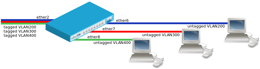
Trunk and Access Ports
- Create a bridge with disabled
vlan-filteringto avoid losing access to the device before VLANs are completely configured.
/interface bridge
add name=bridge1 vlan-filtering=no
- Add bridge ports and specify
pvidfor VLAN access ports to assign their untagged traffic to the intended VLAN.
/interface bridge port
add bridge=bridge1 interface=ether2
add bridge=bridge1 interface=ether6 pvid=200
add bridge=bridge1 interface=ether7 pvid=300
add bridge=bridge1 interface=ether8 pvid=400
- Add Bridge VLAN entries and specify tagged and untagged ports in them.
/interface bridge vlan
add bridge=bridge1 tagged=ether2 untagged=ether6 vlan-ids=200
add bridge=bridge1 tagged=ether2 untagged=ether7 vlan-ids=300
add bridge=bridge1 tagged=ether2 untagged=ether8 vlan-ids=400
- In the end, when VLAN configuration is complete, enable Bridge VLAN Filtering.
/interface bridge set bridge1 vlan-filtering=yes
VLAN Example #2 (Trunk and Hybrid Ports)
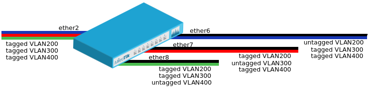
Trunk and Hybrid Ports
- Create a bridge with disabled
vlan-filteringto avoid losing access to the router before VLANs are completely configured.
/interface bridge
add name=bridge1 vlan-filtering=no
- Add bridge ports and specify
pvidon hybrid VLAN ports to assign untagged traffic to the intended VLAN.
/interface bridge port
add bridge=bridge1 interface=ether2
add bridge=bridge1 interface=ether6 pvid=200
add bridge=bridge1 interface=ether7 pvid=300
add bridge=bridge1 interface=ether8 pvid=400
- Add Bridge VLAN entries and specify tagged and untagged ports in them. In this example egress VLAN tagging is done on ether6,ether7,ether8 ports too, making them into hybrid ports.
/interface bridge vlan
add bridge=bridge1 tagged=ether2,ether7,ether8 untagged=ether6 vlan-ids=200
add bridge=bridge1 tagged=ether2,ether6,ether8 untagged=ether7 vlan-ids=300
add bridge=bridge1 tagged=ether2,ether6,ether7 untagged=ether8 vlan-ids=400
- In the end, when VLAN configuration is complete, enable Bridge VLAN Filtering.
/interface bridge set bridge1 vlan-filtering=yes
![]()
Warning: You don’t have to add access ports as untagged ports, they will be added dynamically as untagged port with the VLAN ID that is specified in PVID, you can specify just the trunk port as tagged port. All ports that have the same PVID set will be added as untagged ports in a single entry. You must take into account that the bridge itself is a port and it also has a PVID value, this means that the bridge port also will be added as untagged port for the ports that have the same PVID. You can circumvent this behaviour by either setting different PVID on all ports (even the trunk port and bridge itself), or to use frame-type set to accept-only-vlan-tagged.
VLAN Example #3 (InterVLAN Routing by Bridge)
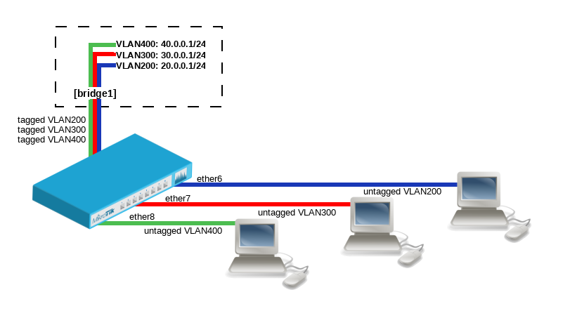
InterVLAN Routing by Bridge
Create a bridge with disabled vlan-filtering to avoid losing access to the router before VLANs are completely configured:
/interface bridge
add name=bridge1 vlan-filtering=no
Add bridge ports and specify pvid for VLAN access ports to assign their untagged traffic to the intended VLAN:
/interface bridge port
add bridge=bridge1 interface=ether6 pvid=200
add bridge=bridge1 interface=ether7 pvid=300
add bridge=bridge1 interface=ether8 pvid=400
Add Bridge VLAN entries and specify tagged and untagged ports in them. In this example bridge1 interface is the VLAN trunk that will send traffic further to do InterVLAN routing:
/interface bridge vlan
add bridge=bridge1 tagged=bridge1 untagged=ether6 vlan-ids=200
add bridge=bridge1 tagged=bridge1 untagged=ether7 vlan-ids=300
add bridge=bridge1 tagged=bridge1 untagged=ether8 vlan-ids=400
Configure VLAN interfaces on the bridge1 to allow handling of tagged VLAN traffic at routing level and set IP addresses to ensure routing between VLANs as planned:
/interface vlan
add interface=bridge1 name=VLAN200 vlan-id=200
add interface=bridge1 name=VLAN300 vlan-id=300
add interface=bridge1 name=VLAN400 vlan-id=400

/ip address
add address=20.0.0.1/24 interface=VLAN200
add address=30.0.0.1/24 interface=VLAN300
add address=40.0.0.1/24 interface=VLAN400
In the end, when VLAN configuration is complete, enable Bridge VLAN Filtering:
/interface bridge set bridge1 vlan-filtering=yes
Management access configuration
There are multiple ways to setup management access on a device that uses bridge VLAN filtering. Below are some of the most popular approaches to properly enable access to a router/switch. Start by creating a bridge without VLAN filtering enabled:
/interface bridge
add name=bridge1 vlan-filtering=no
- In case VLAN filtering will not be used and access with untagged traffic is desired
The only requirement is to create an IP address on the bridge interface.
/ip address
add address=192.168.99.1/24 interface=bridge1
- In case VLAN filtering is used and access from trunk and/or access ports with tagged traffic is desired
In this example VLAN99 will be used to access the device, a VLAN interface on the bridge must be created and an IP address must be assigned to it.
/interface vlan
add interface=bridge1 name=MGMT vlan-id=99
/ip address
add address=192.168.99.1/24 interface=MGMT
For example, if you want to allow access to the router/switch from access ports ether3, ether4 and from trunk port sfp-sfpplus1, then you must add this entry to the VLAN table:
/interface bridge vlan
add bridge=bridge1 tagged=bridge1,ether3,ether4,sfp-sfpplus1 vlan-ids=99
After that you can enable VLAN filtering:
/interface bridge set bridge1 vlan-filtering=yes
- In case VLAN filtering is used and access from trunk and/or access ports with untagged traffic is desired
To allow untagged traffic to access the router/switch, start by creating an IP address on the bridge interface.
/ip address
add address=192.168.88.1/24 interface=bridge1
It is required to add VLAN 1 to ports from which you want to allow the access to the router/switch, for example, to allow access from access ports ether3, ether4 add this entry to the VLAN table:
/interface bridge vlan
add bridge=bridge1 untagged=ether3,ether4 vlan-ids=1
Make sure that PVID on the bridge interface matches the PVID value on these ports:
/interface bridge set bridge1 pvid=1
/interface bridge port set ether3,ether4 pvid=1
After that you can enable VLAN filtering:
/interface bridge set bridge1 vlan-filtering=yes
![]()
Note: If connection to the router/switch through an IP address is not required, then steps adding this IP address can be skipped since connection to the router/switch through Layer2 protocols (e.g. MAC-telnet) will be working either way.
VLAN Tunneling (Q-in-Q)
Since RouterOS v6.43 the RouterOS bridge is IEEE 802.1ad compliant and it is possible to filter VLAN IDs based on Service VLAN ID (0x88A8) rather than Customer VLAN ID (0x8100). The same principals can be applied as with IEEE 802.1Q VLAN filtering (the same setup examples can be used). Below is a topology for a common Provider bridge:
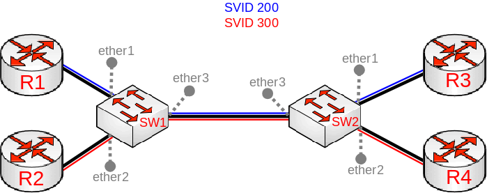
In this example R1, R2, R3 and R4 might be sending any VLAN tagged traffic by 802.1Q (CVID), but SW1 and SW2 needs isolate traffic between routers in a way that R1 is able to communicate only with R3 and R2 is only able to communicate with R4. To do so, you can tag all ingress traffic with a SVID and only allow these VLANs on certain ports. Start by enabling 802.1ad VLAN protocol on the bridge, use these commands on SW1 and SW2:
/interface bridge
add name=bridge1 vlan-filtering=no ether-type=0x88a8
In this setup ether1 and ether2 are going to be access ports (untagged), use the pvid parameter to tag all ingress traffic on each port, use these commands on SW1 and SW2:
/interface bridge port
add interface=ether1 bridge=bridge1 pvid=200
add interface=ether2 bridge=bridge1 pvid=300
add interface=ether3 bridge=bridge1
Specify tagged and untagged ports in the bridge VLAN table, use these commands on SW1 and SW2:
/interface bridge vlan
add bridge=bridge1 tagged=ether3 untagged=ether1 vlan-ids=200
add bridge=bridge1 tagged=ether3 untagged=ether2 vlan-ids=300
When bridge VLAN table is configured, you can enable bridge VLAN filtering, use these commands on SW1 and SW2
/interface bridge set bridge1 vlan-filtering=yes
![]()
Warning: By enabling vlan-filtering you will be filtering out traffic destined to the CPU, before enabling VLAN filtering you should make sure that you set up a Management port. The difference between using different EtherTypes is that you must use a Service VLAN interface. Service VLAN interfaces can be created as regular VLAN interface, but the use-service-tag parameter toggles if the interface will use Service VLAN tag.
![]()
Note: Currently only CRS3xx series switches are capable of hardware offloading VLAN filtering based on SVID (Service VLAN ID) tag when ether-type is set to 0x88a8.
![]()
Warning: When ether-type=0x8100, then the bridge checks the outer VLAN tag if it is using EtherType 0x8100. If the bridge receives a packet with an outer tag that has a different EtherType, it will mark the packet as untagged. Since RouterOS only checks the outer tag of a packet, it is not possible to filter 802.1Q packets when 802.1ad protocol is used.
Tag stacking
Since RouterOS v6.43 it is possible to forcefully add a new VLAN tag over any existing VLAN tags, this feature can be used to achieve a CVID stacking setup, where a CVID (0x8100) tag is added before an existing CVID tag. This type of setup is very similar to Provider bridge setup, to achieve the same setup but with multiple CVID tags (CVID stacking) we can use the same topology:
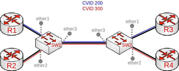
In this example R1, R2, R3 and R4 might be sending any VLAN tagged traffic, it can be 802.1ad, 802.1Q or any other type of traffic, but SW1 and SW2 needs isolate traffic between routers in a way that R1 is able to communicate only with R3 and R2 is only able to communicate with R4. To do so, you can tag all ingress traffic with a new CVID tag and only allow these VLANs on certain ports. Start by selecting the proper EtherType, use these commands on SW1 and SW2:
/interface bridge
add name=bridge1 vlan-filtering=no ether-type=0x8100
In this setup ether1 and ether2 will ignore any VLAN tags that are present and add a new VLAN tag, use the pvid parameter to tag all ingress traffic on each port and allow tag-stacking on these ports, use these commands on SW1 and SW2:
/interface bridge port
add interface=ether1 bridge=bridge1 pvid=200 tag-stacking=yes
add interface=ether2 bridge=bridge1 pvid=300 tag-stacking=yes
add interface=ether3 bridge=bridge1
Specify tagged and untagged ports in the bridge VLAN table, you only need to specify the VLAN ID of the outer tag, use these commands on SW1 and SW2:
/interface bridge vlan
add bridge=bridge1 tagged=ether3 untagged=ether1 vlan-ids=200
add bridge=bridge1 tagged=ether3 untagged=ether2 vlan-ids=300
When bridge VLAN table is configured, you can enable bridge VLAN filtering, which is required in order for the PVID parameter have any effect, use these commands on SW1 and SW2
/interface bridge set bridge1 vlan-filtering=yes
![]()
Warning: By enabling vlan-filtering you will be filtering out traffic destined to the CPU, before enabling VLAN filtering you should make sure that you set up a Management port.
Fast Forward
Fast Forward allows to forward packets faster under special conditions. When Fast Forward is enabled, then the bridge can process packets even faster since it can skip multiple bridge related checks, including MAC learning. Below you can find a list of conditions that MUST be met in order for Fast Forward to be active:
- Bridge has fast-forward set to
yes - Bridge has only 2 running ports
- Both bridge ports support Fast Path, Fast Path is active on ports and globally on the bridge
- Bridge Hardware Offloading is disabled
- Bridge VLAN Filtering is disabled
- bridge DHCP snooping is disabled
- unknown-multicast-flood is set to
yes - unknown-unicast-flood is set to
yes - broadcast-flood is set to
yes - MAC address for the bridge matches with a MAC address from one of the bridge slaves
- horizon for both ports is set to
none
![]()
Note: Fast Forward disables MAC learning, this is by design to achieve faster packet forwarding. MAC learning prevents traffic from flooding multiple interfaces, but MAC learning is not needed when a packet can only be sent out trough just one interface.
![]()
Warning: Fast Forward is disabled when hardware offloading is enabled. Hardware offloading can achieve full write-speed performance when it is active since it will use the built-in switch chip (if such exists on your device), fast forward uses the CPU to forward packets. When comparing throughput results, you would get such results: Hardware offloading > Fast Forward > Fast Path > Slow Path.
It is possible to check how many packets where processed by Fast Forward:
[admin@MikroTik] > /interface bridge settings print
              use-ip-firewall: no
     use-ip-firewall-for-vlan: no
    use-ip-firewall-for-pppoe: no
              allow-fast-path: yes
      bridge-fast-path-active: yes
     bridge-fast-path-packets: 0
       bridge-fast-path-bytes: 0
  bridge-fast-forward-packets: 1279812
    bridge-fast-forward-bytes: 655263744
![]()
Note: If packets are processed by Fast Path, then Fast Forward is not active. Packet count can be used as an indicator whether Fast Forward is active or not.
Since RouterOS 6.44beta28 it is possible to monitor Fast Forward status, for example:
[admin@MikroTik] > /interface bridge monitor bridge1
                  state: enabled
    current-mac-address: D4:CA:6D:E1:B5:82
            root-bridge: yes
         root-bridge-id: 0x8000.00:00:00:00:00:00
         root-path-cost: 0
              root-port: none
             port-count: 2
  designated-port-count: 0
           fast-forward: yes
![]()
Warning: Disabling or enabling fast-forward will temporarily disable all bridge ports for settings to take effect. This must be taken into account whenever changing this property on production environments since it can cause all packets to be temporarily dropped.
IGMP Snooping
IGMP Snooping which controls multicast streams and prevents multicast flooding is implemented in RouterOS starting from version 6.41.
It’s settings are placed in bridge menu and it works independently in every bridge interface.
Software driven implementation works on all devices with RouterOS but CRS1xx/2xx/3xx series switches also support IGMP Snooping with hardware offloading.
Sub-menu: /interface bridge /interface bridge mdb
- Enabling IGMP Snooping on Bridge.
/interface bridge set bridge1 igmp-snooping=yes
- Monitoring multicast groups in the Bridge Multicast Database
[admin@MikroTik] > interface bridge mdb print
BRIDGE                   VID GROUP                                              PORTS
bridge1                  200 229.1.1.2                                          ether3
                                                                                ether2
                                                                                ether1
bridge1                  300 231.1.3.3                                          ether4
                                                                                ether3
                                                                                ether2
bridge1                  400 229.10.10.4                                        ether4
                                                                                ether3
bridge1                  500 234.5.1.5                                          ether5
                                                                                ether1
- Monitoring ports that are connected to a multicast router
[admin@MikroTik] > /interface bridge port monitor [f]
              interface: ether1          ether2
                 status: in-bridge       in-bridge
            port-number: 1               2
                   role: designated-port designated-port
              edge-port: yes             yes
    edge-port-discovery: yes             yes
    point-to-point-port: yes             yes
           external-fdb: no              no
           sending-rstp: yes             yes
               learning: yes             yes
             forwarding: yes             yes
       multicast-router: yes              no
![]()
Note: IGMP membership reports are only forwarded to ports that are connected to a multicast router or to another IGMP Snooping enabled bridge. If no port is marked as a multicast-router then IGMP membership reports will not be forwarded to any port.
DHCP Snooping and DHCP Option 82
Sub-menu: /interface bridge /interface bridge port
Starting from RouterOS version 6.43, bridge supports DHCP Snooping and DHCP Option 82. The DHCP Snooping is a Layer2 security feature, that limits unauthorized DHCP servers from providing a malicious information to users. In RouterOS you can specify which bridge ports are trusted (where known DHCP server resides and DHCP messages should be forwarded) and which are untrusted (usually used for access ports, received DHCP server messages will be dropped). The DHCP Option 82 is an additional information (Agent Circuit ID and Agent Remote ID) provided by DHCP Snooping enabled devices that allows identifying the device itself and DHCP clients.
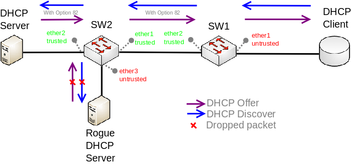
DHCP Snooping and Option 82 setup
In this example, SW1 and SW2 are DHCP Snooping and Option 82 enabled devices. First, we need to create a bridge, assign interfaces and mark trusted ports. Use these commands on SW1:
/interface bridge
add name=bridge
/interface bridge port
add bridge=bridge interface=ether1
add bridge=bridge interface=ether2 trusted=yes
For SW2 configuration will be similar, but we also need to mark ether1 as trusted, because this interface is going to receive DHCP messages with Option 82 already added. You need to mark all ports as trusted if they are going to receive DHCP messages with added Option 82, otherwise these messages will be dropped. Also, we add ether3 to the same bridge and leave this port untrusted, imagine there is an unauthorized (rogue) DHCP server. Use these commands on SW2:
/interface bridge
add name=bridge
/interface bridge port
add bridge=bridge interface=ether1 trusted=yes
add bridge=bridge interface=ether2 trusted=yes
add bridge=bridge interface=ether3
Then we need to enable DHCP Snooping and Option 82. In case your DHCP server does not support DHCP Option 82 or you do not implement any Option 82 related policies, this option can be disabled. Use these commands on SW1 and SW2:
/interface bridge
set [find where name="bridge"] dhcp-snooping=yes add-dhcp-option82=yes
Now both devices will analyze what DHCP messages are received on bridge ports. The SW1 is responsible for adding and removing the DHCP Option 82. The SW2 will limit rogue DHCP server form receiving any discovery messages and drop malicious DHCP server messages from ether3.
![]()
Note: Currently only CRS3xx devices fully support hardware DHCP Snooping and Option 82. For CRS1xx and CRS2xx series switches it is possible to use DHCP Snooping along with VLAN switching, but then you must make sure that DHCP packets are sent out with the correct VLAN tag using egress ACL rules. Other devices are capable of using DHCP Snooping and Option 82 features along with hardware offloading, but you must make sure that there is no VLAN related configuration applied on the device, otherwise DHCP Snooping and Option 82 might not work properly. See Bridge Hardware Offloading section with supported features.
Bridge Firewall
Sub-menu: /interface bridge filter, /interface bridge nat
The bridge firewall implements packet filtering and thereby provides security functions that are used to manage data flow to, from and through bridge.
Packet flow diagram shows how packets are processed through router. It is possible to force bridge traffic to go through /ip firewall filter rules (see: Bridge Settings)
There are two bridge firewall tables:
- filter — bridge firewall with three predefined chains:
- input — filters packets, where the destination is the bridge (including those packets that will be routed, as they are destined to the bridge MAC address anyway)
- output — filters packets, which come from the bridge (including those packets that has been routed normally)
- forward — filters packets, which are to be bridged (note: this chain is not applied to the packets that should be routed through the router, just to those that are traversing between the ports of the same bridge)
- nat — bridge network address translation provides ways for changing source/destination MAC addresses of the packets traversing a bridge. Has two built-in chains:
- srcnat — used for «hiding» a host or a network behind a different MAC address. This chain is applied to the packets leaving the router through a bridged interface
- dstnat — used for redirecting some packets to other destinations
You can put packet marks in bridge firewall (filter and NAT), which are the same as the packet marks in IP firewall put by '/ip firewall mangle'. In this way, packet marks put by bridge firewall can be used in ‘IP firewall’, and vice versa.
General bridge firewall properties are described in this section. Some parameters that differ between nat and filter rules are described in further sections.
Properties
| Property | Description |
|---|---|
| 802.3-sap (integer; Default: ) | DSAP (Destination Service Access Point) and SSAP (Source Service Access Point) are 2 one byte fields, which identify the network protocol entities which use the link layer service. These bytes are always equal. Two hexadecimal digits may be specified here to match a SAP byte. |
| 802.3-type (integer; Default: ) | Ethernet protocol type, placed after the IEEE 802.2 frame header. Works only if 802.3-sap is 0xAA (SNAP — Sub-Network Attachment Point header). For example, AppleTalk can be indicated by SAP code of 0xAA followed by a SNAP type code of 0x809B. |
| action (accept | drop | jump | log | mark-packet | passthrough | return | set-priority; Default: ) | Action to take if packet is matched by the rule:
|
| arp-dst-address (IP address; Default: ) | ARP destination IP address. |
| arp-dst-mac-address (MAC address; Default: ) | ARP destination MAC address |
| arp-gratuitous (yes | no; Default: ) | Matches ARP gratuitous packets. |
| arp-hardware-type (integer; Default: 1) | ARP hardware type. This is normally Ethernet (Type 1). |
| arp-opcode (arp-nak | drarp-error | drarp-reply | drarp-request | inarp-reply | inarp-request | reply | reply-reverse | request | request-reverse; Default: ) | ARP opcode (packet type)
|
| arp-packet-type (integer 0..65535 | hex 0x0000-0xffff; Default: ) | ARP Packet Type. |
| arp-src-address (IP address; Default: ) | ARP source IP address. |
| arp-src-mac-address (MAC addres; Default: ) | ARP source MAC address. |
| chain (text; Default: ) | Bridge firewall chain, which the filter is functioning in (either a built-in one, or a user-defined one). |
| dst-address (IP address; Default: ) | Destination IP address (only if MAC protocol is set to IP). |
| dst-mac-address (MAC address; Default: ) | Destination MAC address. |
| dst-port (integer 0..65535; Default: ) | Destination port number or range (only for TCP or UDP protocols). |
| in-bridge (name; Default: ) | Bridge interface through which the packet is coming in. |
| in-interface (name; Default: ) | Physical interface (i.e., bridge port) through which the packet is coming in. |
| in-interface-list (name; Default: ) | Set of interfaces defined in interface list. Works the same as in-interface. |
| ingress-priority (integer 0..63; Default: ) | Matches the priority of an ingress packet. Priority may be derived from VLAN, WMM, DSCP or MPLS EXP bit. read more» |
| ip-protocol (dccp | ddp | egp | encap | etherip | ggp | gre | hmp | icmp | icmpv6 | idpr-cmtp | igmp | ipencap | ipip | ipsec-ah | ipsec-esp | ipv6 | ipv6-frag | ipv6-nonxt | ipv6-opts | ipv6-route | iso-tp4 | l2tp | ospf | pim | pup | rdp | rspf | rsvp | sctp | st | tcp | udp | udp-lite | vmtp | vrrp | xns-idp | xtp; Default: ) | IP protocol (only if MAC protocol is set to IPv4)
|
| jump-target (name; Default: ) | If action=jump specified, then specifies the user-defined firewall chain to process the packet. |
| limit (integer/time,integer; Default: ) | Restricts packet match rate to a given limit.
|
| log-prefix (text; Default: ) | Defines the prefix to be printed before the logging information. |
| mac-protocol (802.2 | arp | homeplug-av | ip | ipv6 | ipx | length | lldp | loop-protect | mpls-multicast | mpls-unicast | packing-compr | packing-simple | pppoe | pppoe-discovery | rarp | service-vlan | vlan | integer 0..65535 | hex 0x0000-0xffff; Default: ) | Ethernet payload type (MAC-level protocol). To match protocol type for VLAN encapsulated frames (0x8100 or 0x88a8), a vlan-encap property should be used.
|
| out-bridge (name; Default: ) | Outgoing bridge interface. |
| out-interface (name; Default: ) | Interface that the packet is leaving the bridge through. |
| out-interface-list (name; Default: ) | Set of interfaces defined in interface list. Works the same as out-interface. |
| packet-mark (name; Default: ) | Match packets with certain packet mark. |
| packet-type (broadcast | host | multicast | other-host; Default: ) | MAC frame type:
|
| src-address (IP address; Default: ) | Source IP address (only if MAC protocol is set to IPv4). |
| src-mac-address (MAC address; Default: ) | Source MAC address. |
| src-port (integer 0..65535; Default: ) | Source port number or range (only for TCP or UDP protocols). |
| stp-flags (topology-change | topology-change-ack; Default: ) | The BPDU (Bridge Protocol Data Unit) flags. Bridge exchange configuration messages named BPDU periodically for preventing loops
|
| stp-forward-delay (integer 0..65535; Default: ) | Forward delay timer. |
| stp-hello-time (integer 0..65535; Default: ) | STP hello packets time. |
| stp-max-age (integer 0..65535; Default: ) | Maximal STP message age. |
| stp-msg-age (integer 0..65535; Default: ) | STP message age. |
| stp-port (integer 0..65535; Default: ) | STP port identifier. |
| stp-root-address (MAC address; Default: ) | Root bridge MAC address. |
| stp-root-cost (integer 0..65535; Default: ) | Root bridge cost. |
| stp-root-priority (integer 0..65535; Default: ) | Root bridge priority. |
| stp-sender-address (MAC address; Default: ) | STP message sender MAC address. |
| stp-sender-priority (integer 0..65535; Default: ) | STP sender priority. |
| stp-type (config | tcn; Default: ) | The BPDU type:
|
| tls-host (string; Default: ) | Allows to match https traffic based on TLS SNI hostname. Accepts GLOB syntax for wildcard matching. Note that matcher will not be able to match hostname if TLS handshake frame is fragmented into multiple TCP segments (packets). |
| vlan-encap (802.2 | arp | ip | ipv6 | ipx | length | mpls-multicast | mpls-unicast | pppoe | pppoe-discovery | rarp | vlan | integer 0..65535 | hex 0x0000-0xffff; Default: ) | Matches the MAC protocol type encapsulated in the VLAN frame. |
| vlan-id (integer 0..4095; Default: ) | Matches the VLAN identifier field. |
| vlan-priority (integer 0..7; Default: ) | Matches the VLAN priority (priority code point) |
Notes
- STP matchers are only valid if destination MAC address is 01:80:C2:00:00:00/FF:FF:FF:FF:FF:FF (Bridge Group address), also
stpshould be enabled.
- ARP matchers are only valid if mac-protocol is
arporrarp
- VLAN matchers are only valid for
0x8100or0x88a8ethernet protocols
- IP or IPv6 related matchers are only valid if mac-protocol is either set to
iporipv6
- 802.3 matchers are only consulted if the actual frame is compliant with IEEE 802.2 and IEEE 802.3 standards (note: it is not the industry-standard Ethernet frame format used in most networks worldwide!). These matchers are ignored for other packets.
Bridge Packet Filter
Sub-menu: /interface bridge filter
This section describes bridge packet filter specific filtering options, that are specific to '/interface bridge filter'.
Properties
| Property | Description |
|---|---|
| action (accept | drop | jump | log | mark-packet | passthrough | return | set-priority; Default: accept) | Action to take if packet is matched by the rule:
|
Bridge NAT
Sub-menu: /interface bridge nat
This section describes bridge NAT options, that are specific to '/interface bridge nat'.
Properties
| Property | Description |
|---|---|
| action (accept | drop | jump | mark-packet | redirect | set-priority | arp-reply | dst-nat | log | passthrough | return | src-nat; Default: accept) | Action to take if packet is matched by the rule:
|
| to-arp-reply-mac-address (MAC address; Default: ) | Source MAC address to put in Ethernet frame and ARP payload, when action=arp-reply is selected |
| to-dst-mac-address (MAC address; Default: ) | Destination MAC address to put in Ethernet frames, when action=dst-nat is selected |
| to-src-mac-address (MAC address; Default: ) | Source MAC address to put in Ethernet frames, when action=src-nat is selected |
See also
- CRS1xx/2xx series switches
- CRS3xx series switches
- Swith chip features
- MTU on RouterBOARD
- Layer2 misconfiguration
- Bridge VLAN Table
- Wireless VLAN Trunk
- VLANs on Wireless
[ Top | Back to Content ]

Благодарим за помощь Сергея Бределева @seregasafe

5196
Bridge – это устройства, которые работают на L2 и, по сути, соединяют между собой некоторые интерфейсы.
Традиционно когда-то давным-давно использовали для соединения сегментов сети и традиционно решали вопросы с разделениями домена коллизий на несколько доменов коллизий, то есть по большому счету в моменте, когда были hub, везде присутствовал домен коллизии и были с этим определенные проблемы.
В hub мы не могли «втыкать» бесконечное кол-во устройств, потому что чем больше устройств находилось в hub тем больше вероятность получить коллизию в локальной сети.
Bridge
- Bridges это устройства OSI layer 2
- Bridge это прозрачный девайс
- Традиционно используется для соединения двух сегментов сети
- Bridge разделяет область коллизий на две части
- Сетевой switch это multi-port bridge – каждый порт является доменом коллизий одного устройства
- Все хосты могут взаимодействовать друг с другом
- Все используют один и тот же домен коллизий
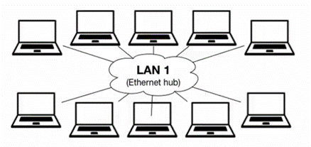
С Bridge область коллизии делилась на несколько частей и по большому счету мы могли увеличивать кол-во устройств которые работают в локальной сети.
- Все хосты по-прежнему могут взаимодействовать друг с другом
- Теперь есть две области коллизий
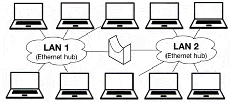
Все MikroTik работающие под Router OS поддерживают software bridge.
Какие устройства могут быть включены в bridge и что мы можем добавить в bridge? Это прежде всего Ethernet, wi-fi, SFP, Eoip, Open VPN (работающие в режиме ethernet или tap driver), vpls, vlan интерфейсы и т. д.
Основное отличие этих интерфейсов то, что через себя эти интерфейсы должны уметь передавать L2 кадры.
Если мы говорим про default configuration, когда мы берем софт устройства то в bridge, находится wi-fi интерфейсы и все интерфейсы ethernet (имеют опцию Hardware offload и используют аппаратный switch chip в случае его наличия)
- Router OS поддерживает software bridge
- Ethernet, wireless, SFP и туннельные интерфейсы могут быть добавлены в bridge
- В Default configuration в SOHO routers в bridge находятся wireless интерфейс и ether2 port
- Ether2-5 объединены в switch
- Ether2 является master, 3-5 slave — используется аппаратный switch chip
Bridge => Bridge
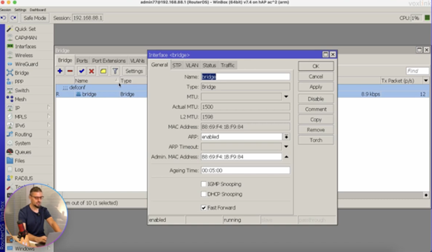
В default configuration присутствует один bridge c комментарием defconf и наименованием bridge
Bridge => Ports
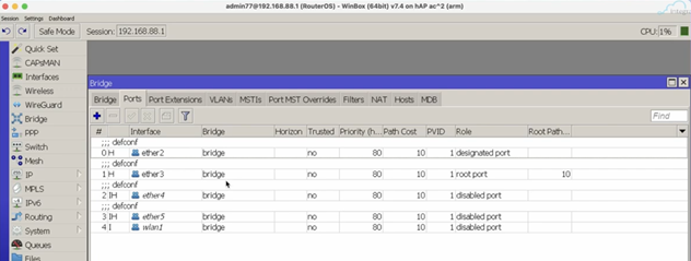
На вкладке Ports присутствуют все интерфейсы, которые добавлены в bridge. В данном случае у нас добавлены все ethernet интерфейсы (ether2, ether3, ether4, ether5). Ether1 – будет использован для выхода в интернет. Добавлен wi-fi интерфейс – wlan1. В default configuration так же добавлен wlan2.
Если у нас есть switch chip — это мы можем понять по наличию раздела switch в основном меню.
Switch => Switch
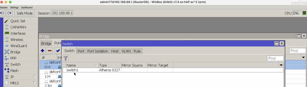
Type = Atheros8327 – модель switch chip
Switch => Port
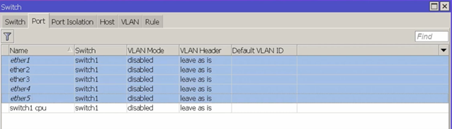
Порты, которые включены в данный switch
Bridge => Ports => ether2 => General
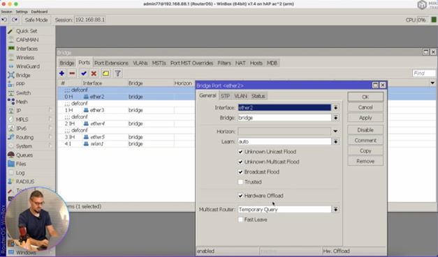
Hardware offload – это опция, позволяющая аппаратно передавать кадры между портами на максимальной скорости
Если у нас общаются несколько устройств через интерфейсы, например с интерфейса ether2 на ether3 отправляются кадры, которые предназначаются от одного сервера к другому, то будет использоваться максимальная скорость (т. е. скорость порта, например 1 Gb/s). Данная опция может быть отключена. Зачем это необходимо? Зачем нарочно снижать производительность устройства если можно этого не делать? Дело в том, что Hardware offload (Hw. Offload) он как Форрест Гамп – быстрый и глупый т.е. его задача быстро перекладывать данные с одного интерфейса на другой, а если нам нужна какая-то дополнительная обработка, если в задачу входит профильтровать кадры, поменять mac адрес, что-то посчитать то в данном случае Hw. Offload нам будет мешать и в такой ситуации его придется отключить. Так же стоит отметить, что включение некоторых опций на некоторых switch chip. Например, включение bridge VLAN Filtering полностью выключает Hw. Offload
Bridge => Bridge => Interface bridge => VLAN
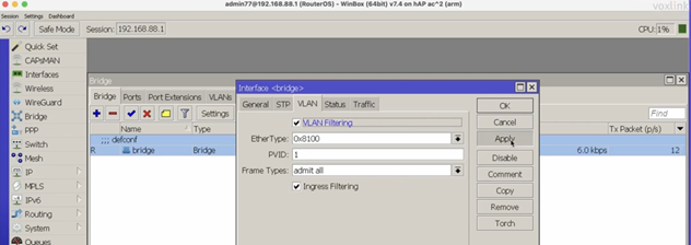
Тем самым весь трафик идет через центральный процессор, т. е. в данном случае снизили производительность устройства.
Bridge => Hosts
Hosts – это таблица mac адресов, которые работают через bridge. Здесь у нас указан какой mac адрес через какой интерфейс мы его видим и в случае наличия bridge VLAN Filtering мы видим VLAN. Так же есть опция что это динамически (D) добавленные mac адреса в таблицу bridge. Через какое-то время эти mac адреса могут быть удалены. DL – показывает, что это mac адреса конкретных интерфейсов.
На чтение 7 мин. Просмотров 12.7k.
В RouterOS есть два способа коммутации портов.
Содержание
- Коммутация портов MikroTik через Switch (Master Port)
- Коммутация в MikroTik через Bridge-interface
- Пропала опция Master-port и поле Switch
Коммутация портов MikroTik через Switch (Master Port)

В этом случае коммутация производится через чип свитча, в обход центрального процессора маршрутизатора. Обычно в SOHO маршрутизаторах Mikrotik используется одна свитч-группа на 5 портов, если портов больше — две свитч-группы. В устройствах Cloud Router Switch чипы коммутации на больше портов и имеют больше возможностей, подробней на них мы останавливаться в этой статье не будем.
Настроить коммутацию можно в разделе General каждого порта, просто выбрав в пункте Master Port. Это главный порт, через который будет происходить коммутация. Коммутация позволяет достичь проводной скорости обмена данными между портами одной группы, как между портами в обычном Ethernet-коммутаторе. Основной (master) порт будет являться портом, через который RouterOS будет сообщаться со всеми остальными портами данной группы. Интерфейсы, для которых задан master-порт, становятся неактивны – не учитывается поступивший и отправленный трафик. Фактически, как будто мы объединили порты физическим, «тупым» коммутатором (свитчем). В роутерах Mikrotik применяются следующие чипы коммутации:
- Atheros 8316 представлен в платах RB493G (ether1+ether6-ether9, ether2-ether5), RB1200 (ether1-ether5), RB450G (все порты (ether1 опционально)),RB435G (все порты (ether1 опционально)), RB750G, и в RB1100 (ether1-ether5, ether6-ether10).
- Atheros 8327 представлен в платах серии RB2011 (ether1-ether5+sfp1), RB750GL, RB751G-2HnD, а также в RB1100AH и RB1100AHx2 (ether1-ether5, ether6-ether10).
- Atheros8227 представлен в платах серии RB2011 (ether6-ether10).
- Atheros 7240 представлен в RB750 (ether2-ether5), RB750UP (ether2-ether5), RB751U-2HnD (ether2-ether5) и RB951-2n.
- ICPlus 175D представлен в более новых ревизиях RB450 (ether2-ether5) и в платах серии RB433 (ether2-ether3).
- ICPlus 175C представлен в некоторых RB450 (ether2-ether5) и в некоторых платах серии RB433 (ether2-ether3).
- ICPlus 178C представлен в платах серии RB493 (ether2-ether9) и в RB816.
Возможности чипов коммутации:
| Возможности | Atheros 8316 | Atheros 8327 | Atheros 7240 | ICPlus 175D | Другие |
|---|---|---|---|---|---|
| Коммутация портов | да | да | да | да | да |
| Зеркалирование портов | да | да | да | да | нет |
| Таблица MAC-адресов | 2000 записей | 2000 записей | 2000 записей | нет | нет |
| Vlan-таблица | 4096 записей | 4096 записей | 16 записей | нет | нет |
| Таблица правил | 32 правила | 92 правила | нет | нет | нет |
* Порт ether1 на RB450G имеет особенность, которая позволяет ему быть исключённым/добавленным из/в коммутируемой(ую) группы(у) по умолчанию. По умолчанию порт ether1 будет включён в группу коммутации. Данная конфигурация может быть изменена с помощью команды
"/interface ethernet switch set switch1 switch-all-ports=no".
switch-all-ports=yes/no:
"yes" означает, что порт ether1 является портом коммутатора и поддерживает создание групп коммутации и все остальные расширенные возможности чипа Atheros8316, включая расширенную статистику (/interface ethernet print stats)."no" означает, что порт ether1 не является частью коммутатора, что, фактически, делает его самостоятельным Ethernet-портом – это способ увеличения пропускной способности между ним и другими портами в режимах сетевого моста и маршрутизации, но в то же время исключает возможность коммутации на этом порту. Коммутация через Switch является самой быстрой и производительной в маршрутизаторе, в тоже время имеет наименьшее количество возможностей. При этом:
- master Port можно назначить ТОЛЬКО внутри каждой группы;
- master Port может быть только ОДИН внутри switch-чипа;
- «Master» и «Slave» для чипа коммутации считаются равными;
- одно различие между «master» и «slave» — ТОЛЬКО главный порт обращается к CPU напрямую, ему назначается IP, он объединяется в Bridge и т.д.
- Две switch-group объединяются уже через bridge. В таком bridge будет только два master-port, ну может еще wifi, если такой есть (В этом случае трафик между двумя switch-group будет проходить через процессор.)
Итого, можно выделить несколько особенностей такого метода:
- каждый новый RouterBOARD с несколько Ethernet интерфейсам оснащен чипом Switch;
- при коммутации не используются ресурсы процессора;
- с ROS v.6 поддерживается VLAN Trunking (разруливать VLAN-ны можно без потери производительности основного ЦП).
Коммутация в MikroTik через Bridge-interface

Порты объединяются не напрямую, а программно, используя ресурсы центрального процессора маршрутизатора. К портам могут быть применены фильтры брандмауэра. Такое объединение так-же влияет на прохождение пакетов по упрощенной схеме (Fastpath). Если взять в пример 2011-серию маршрутизаторов, то ether1-ether5 объеденены в switch1 (Atheros 8327) а ether6-ether10 в switch2 (Atheros 8227), вы можете использовать только Bridge для объединения их в одно целое. Особенность данного метода:
- можно маршрутизировать и фильтровать пакеты между портами;
- возрастает нагрузка на процессор;
- можно объединять любые порты маршрутизатора;
- Wi-Fi интерфейс коммутируется ТОЛЬКО через Bridge;
- после объединения портов в Bridge IP-адрес назначается на «интерфейс Bridge», в классическом firewall правила применяем ко всем виртуальному интерфейсу. Правила применимые к портам прописываем в Bridge — NAT, Bridge — Filters;
- VLAN проходит через ЦП устройства Mikrotik.
Коммутация позволяет достичь проводной скорости (wire speed) обмена данными между портами одной группы, как между портами в обычном Ethernet-коммутаторе.
Пока пакет не достиг cpu-порта, его обработка полностью осуществляется логикой коммутатора, не требуя какого-либо участия центрального процессора, и эта обработка происходит с проводной скоростью при любом размере кадра.
Пропала опция Master-port и поле Switch
Не пугайтесь, это нормально, если прошивка вашего роутера 6.41 и выше. Теперь вся информация, которая передается на втором уровне модели OSI, будет передаваться через Bridge. Использование swich-чипа (hw-offload) будет автоматически активировано автоматически в случае такой возможности. По умолчанию при добавлении любого интерфейса в Bridge у него будет активирована опция «Hardware Offload», которая будет передавать всю информацию 2-го уровня через switch-чип. Если эту опцию убрать, то обработка будет осуществляться силами операционной системы.
При обновлении на RouterOS 6.41 и выше с RouterOS версий 6.40.5 и ниже все настройки master-port будут автоматически перенесены в Bridge-интерфейс. Если произвести downgrade до версии, которая поддерживает master-port, то настройки не будут возвращены на место. Настоятельно рекомендуется сделать резервную копию до обновления.
До обновления до RouterOS 6.41:
/interface ethernet set [ find default-name=ether1 ] name=ether1-WAN1 set [ find default-name=ether5 ] name=ether5-LAN1-master set [ find default-name=ether2 ] master-port=ether5-LAN1-master name=ether2-LAN1 set [ find default-name=ether3 ] master-port=ether5-LAN1-master name=ether3-LAN1 set [ find default-name=ether4 ] master-port=ether5-LAN1-master name=ether4-LAN1 /ip address add address=10.10.10.1/24 interface=ether1-WAN1 network=10.10.10.0 add address=192.168.0.1/24 interface=ether5-LAN1-master network=192.168.0.0 /ip firewall nat add action=masquerade chain=srcnat out-interface=ether1-WAN1
После обновления на RouterOS 6.41 и старше:
/interface bridge add admin-mac=6C:3B:6B:4A:80:3D auto-mac=no comment="created from master port" name=bridge1 protocol-mode=none /interface ethernet set [ find default-name=ether1 ] name=ether1-WAN1 set [ find default-name=ether2 ] name=ether2-LAN1 set [ find default-name=ether3 ] name=ether3-LAN1 set [ find default-name=ether4 ] name=ether4-LAN1 set [ find default-name=ether5 ] name=ether5-LAN1-master /interface bridge port add bridge=bridge1 interface=ether2-LAN1 add bridge=bridge1 interface=ether3-LAN1 add bridge=bridge1 interface=ether4-LAN1 add bridge=bridge1 interface=ether5-LAN1-master /ip neighbor discovery-settings set discover-interface-list=!dynamic /ip address add address=10.10.10.1/24 interface=ether1-WAN1 network=10.10.10.0 add address=192.168.0.1/24 interface=bridge1 network=192.168.0.0 /ip firewall nat add action=masquerade chain=srcnat out-interface=ether1-WAN1
Обсуждение на форуме Mikrotik https://forum.mikrotik.com/viewtopic.php?t=128915
Данная инструкция предназначена для самостоятельной настройки роутера MikroTik. В качестве примера будет использоваться роутер MikroTik hAP ac lite(RB952Ui-5ac2nD), который будет настроен для работы интернета и использования локальных сетей Ethernet и WiFi(включая Apple Iphone).
Инструкция состоит из двух больших примеров: “Быстрая настройка” и ‘Ручная настройка“, задача которых состоит в демонстрации двух методов настроек: с помощью внутреннего мастера настроек Quick Set и распределённая настройка посредством Winbox или Webfig.
№1. Быстрая настройка
- Сброс роутера
- Подключение по кабелю
- Подключение по WiFi
- Вход в настройки
- Quick Set настройка
- Обновление прошивки
- Настройка WiFi
- Настройка интернета, автоматические настройки
- Настройка интернета, статический IP
- Настройка интернета, PPPoE
- Настройка LAN
№2. Ручная настройка
- Подключение к ПК
- Вход в настройки
- Ошибки Winbox
- Сброс роутера
- Установить пароль
- Обновить прошивку
- Настройка LAN
- DHCP сервера
- DNS
- Настройка интернета
- DHCP клиент
- Статический IP
- PPPOE
- Настройка WiFi
- WiFi 2G
- WiFi 5G
- Проброс портов
- Настройка FireWall
- Сброс на заводские настройки
- Задать вопрос по настройке MikroTik
Нужна настройка MikroTik в базовой конфигурации?
Настройка служб на роутерах MikroTik: подключение интернета, DHCP, brige, VLAN, WiFi, Capsman, VPN, IpSec, PPTP, L2TP, Mangle, NAT, проброс портов, маршрутизация(routing), удаленное подключение и объединение офисов.
Пример №1. Быстрая настройка MikroTik
Данный пример настройки роутера MikroTik самый простой и не требует детального изучения принципов работы MikroTik. Его можно применять с использованием ПК или ноутбука, а также мобильного телефона.
Исходные настройки роутера MikroTik должны соответствовать заводским, если по какой причине это не так, следует их сбросить через кнопку Reset.
ВАЖНО: при использовании кнопки RESET оборудование MikroTik может принимать 3 разных состояния. Переход между состоянии зависит от времени нажатия кнопки RESET. Внимательно изучите последовательность сброса для перехода к заводским настройкам.
Сброс через кнопку RESET
На задней панели расположена кнопка RESET

Необходимо последовательно совершить действия:
- Отключить питание роутера;
- Нажать и держать кнопку Reset;
- Включить питание роутера(Reset нажат);
- Подождать 5-6сек., в этот момент должен замигать какой-то индикатор(ACT|SYS| или другой);
- Как только замигал индикатор. отпустить Reset.
Подключение роутера MikroTik по кабелю
- Включить роутер MikroTik в электросеть;
- На порт ether1 – подключить интернет провайдера(WAN);
- На любой порт из ether2-ether5 подключить компьютер. Эти порты считаются локальными (LAN).

Подключение роутера MikroTik по WiFi
Подключение к роутеру MikroTik через WiFi может стать актуальным, если у ноутбука нет Ethernet порта или настройка роутера производится через смартфон. В списке доступных WiFi подключений должен отображаться роутер MikroTik, по аналогии как на примере ниже.

Вход в настройки роутера MikroTik
Для входа в настройки MikroTik можно воспользоваться любым web браузером.

- Отрыть web браузер;
- В адресной строке ввести IP адрес 192.168.88.1 и нажать переход(Enter);
- Авторизоваться на роутере MikroTik с помощью учётных данных по умолчанию(Login: admin, Password: пустой).

Настройка MikroTik с помощью Quick Set
Quick Set это мастер быстрых настроек, который содержит оптимизированные шаблоны уже готовых конфигураций, достаточно только их заполнить пользовательскими данными. В рамках данной настройки будет выбран шаблон Home AP Dual.

Обновление прошивки
- Нажать кнопку Check For Updates;
- Установить Channel = long term;
- Нажать кнопку Download&Install.


Роутер MikroTik будет перезагружен и после будет доступен по прежнему адресу “192.168.88.1“.
Настройка MikroTik WiFi
- Заполнить Network Name для 2GHz и 5GHz;
- Frequency = auto;
- Band 2GHz = 2GHz-B-G-N, Band 5GHz = 5GHz-A-N-AC
- Country = no_country_set
- Заполнить WiFi Password.

Настройка интернета, автоматические настройки
- Выбрать Address Acquusition = Automatic.

Настройка интернета, статический IP адрес
- Выбрать Address Acquusition = Static;
- Заполнить параметрами выданные провайдером: IP Address, Netmask, Gateway, DNS Servers.

Настройка интернета, PPPoE
- Выбрать Address Acquusition = PPPoE;
- Заполнить параметрами выданные провайдером: PPPoE User, PPPoE Password.

Настройка локальной сети
- Заполнить IP Address;
- Netmask 255.255.255.0 (/24);
- Включить DHCP Server;
- Заполнить DHCP Server Range;
- Включить NAT.

Пример №2. Ручная настройка MikroTik
Подключение роутера MikroTik к компьютеру
Предварительно стоит отметить, что у роутера MikroTik в качестве порта WAN может выступать любой порт. Однако в заводской прошивке, в качестве WAN порта выступает ether1, на котором активен dhcp client. Эту особенность заводской прошивки стоит учитывать при подключении к роутеру MikroTik, т.к. конфигурация определена так, что все входящие подключения на ether1 будут недоступны.
- Включить роутер MikroTik в электро сеть;
- На порт ether1 – подключить интернет провайдера(WAN);
- На любой порт из ether2-ether5 подключить компьютер. Эти порты считаются локальными (LAN).
Вход в настройки MikroTik RouterOS
Для настройки роутера MikroTik лучше всего воспользоваться утилитой Winbox, которая специально разработана для управления оборудованием MikroTik.
Winbox обнаружит устройство независимо от назначенного ему адреса. Чаще всего это 192.168.88.1, но и встречаются варианты когда ip адрес = «0.0.0.0». В этом случае подключение происходит по MAC адресу устройства. Кроме этого Winbox отображается все найденные устройства MikroTik в сети, а также дополнительную информацию(версия прошивки, UpTime):

- Запустить утилиту Winbox для настройки MikroTik;
- Среди списка устройств выбрать нужный роутер MikroTik и нажать кнопку Connect;
Учётная запись(пароль) по умолчанию:
- пользователь = «admin»
- пароль = «»(пустой)
Сброс роутера MikroTik
Т.к. ручная настройка предполагает полную настройку роутера MikroTik с нуля, при первом подключении необходимо полностью удалить заводскую настройку.

Если по какой-то причине роутер MikroTik не вывел форму сброса, это можно сделать в ручном режиме.
Reset через Winbox
Настройка находится в System→Reset Configuration
- Установить переключатели No Default Configuration и Do Not Backup;
- Нажать кнопку Reset Configuration.

/system reset-configuration no-defaults=yes skip-backup=yes
Сброс роутера MikroTik будет сопровождаться перезагрузкой устройства, после которой можно повторно подключиться к роутеру через MAC адрес.
Ошибки при подключении к Winbox
ERROR: router does not support secure connection, please enable legacy mode if you want to connect anyway
Решение: необходимо активировать режим Legacy Mode.

ERROR: wrong username or passwords
Решение-1: Недопустимые учётные данные(неверное имя пользователя или пароль). За доступом нужно обратиться к администратору устройства или сделать сброс к заводским настройкам →.
Решение-2: Обновить версию Winbox.
ERROR: could not connect to MikroTik-Ip-Address
Решение: Проблема связана с доступом, частые причины:
- Подключение закрыто через Firewall;
- Изменён порт управления через Winbox с 8291 на другой;
- Подключение происходит через WAN порт, интернет провайдер которого блокирует подобные соединения;
Установить пароль на роутер MikroTik
Первым важным делом настройки нового роутера MikroTik это обновление пароля администратора. Случаи бывали разные, это пункт просто нужно выполнить.
Настройка находится в System→Users
- Нажать + и добавить новую учётную запись администратора;
- Заполнить параметры: Name, Group, Password;
- Открыть учётную запись admin и деактивировать кнопкой Disable.

добавление нового пользователя с полными правами:
/user add name="admin-2" password="PASSWORD" group=full
деактивация старого пользователя:
/user set [find name="admin"] disable="yes"
Рекомендация: Для повышения уровня безопасности роутера MikroTik следует:
- создать и использовать новую учётную запись с полными правами(full);
- на учётной записи по умолчанию (admin) изменить пароль и деактировать.
Обновление прошивки в MikroTik RouterOS
Одной из важной задачей при вводе в эксплуатацию нового устройства MikroTik: маршрутизатора(роутера), коммутатора(свитча) или точки доступа WiFi это обновление прошивки. Чаще всего это имело рекомендованный характер, но недавний инцидент с “back door” в категории long-term указал на то, что актуальность прошивки в устройствах MikroTik имеет критический характер.
Настройка находится в System→Packages
- Нажать кнопку Check For Updates;
- Выбрать Channel = long term;
- Загрузить и установить прошивку на MikroTik кнопкой Download&Install.

Действия в кнопке Download&Install произведут закачку выбранной редакции прошивки и автоматическую перезагрузку роутера MikroTik. Установка будет произведена в момент загрузки. Не выключайте роутер MikroTik до полной перезагрузки и обеспечьте стабильное питание электросети при обновлении прошивки.

Редакции прошивок MikroTik
- long term(bug fix only) – самая стабильная версия. Рекомендовано для производственных сред!
- stable(current) – long term плюс поддержка новых функций. Новые технологии это всегда хорошо.
Другие редакции не рекомендуется устанавливать в рабочие устройства MikroTik, т.к. это может привести к нежелательным последствиям.
Важным дополнением в обновлении прошивки является обновление Current Firmware – это аппаратная прошивка, аналог BIOS в компьютере.
Настройка находится тут System→Routerboard

Изменения вступят в силу после перезагрузки устройства MikroTik(System→Reboot).
Настройка локальной сети MikroTik LAN
В основе работы локальной сети (LAN) на роутере MikroTik находится Bridge – программное объединение портов в свитч. В состав Bridge может входить любая последовательность портов роутера MikroTik, а если туда добавить все порты – роутер станет точкой доступа WiFi или коммутатором.
Стоит учитывать, что такое объединение управляется CPU. Этот факт важен при значительных нагрузках на CPU.
Настройка LAN на роутере MikroTik состоит из следующих ключевых этапов:
- Объединение все локальных портов в Bridge;
- Настройка локального IP адреса для роутера MikroTik;
- Настройка DHCP сервера.
Настройка MikroTik Bridge
Настройка находится в основном меню Bridge→Bridge
- Нажать + и добавить новый Bridge;
- Присвоить Name для выбранного Bridge;
- Нажать кнопку Apply и скопировать значение MAC Address в Admin MAC Address;

Копирование значения MAC Address в Admin MAC Address исключить ошибку:
ether3:bridge port received packet with own address as source address (MAC ether3), probably loop”
/interface bridge add name=bridge-1
Добавление портов MikroTik в Bridge
Настройка находится в основном меню Bridge→Ports
- Нажать + и добавить новый Port;
- Выбрать соответствующие значение в параметрах: Interface, Bridge;
- Повторить аналогичные действия для всех интерфейсов, которые определены как LAN.

добавление портов(LAN, VLAN, WLAN и тд)
/interface bridge port add bridge=bridge-1 hw=yes interface=ether2
/interface bridge port add bridge=bridge-1 hw=yes interface=ether3
/interface bridge port add bridge=bridge-1 hw=yes interface=ether4
/interface bridge port add bridge=bridge-1 hw=yes interface=ether5

/interface bridge port add bridge=bridge-1 interface=wlan1
/interface bridge port add bridge=bridge-1 interface=wlan2
Hardware Offload — аппаратная поддержка bridge отдельным чипом. Список поддерживаемых устройств.
По итогам, закладка Bridge→Ports должна иметь вид:

Назначение локального IP адреса
После добавления портов в Bridge нужно назначить статический IP адрес и правильней всего это указать в качестве интерфейса созданный bridge-1. С этого момента любая настройка адресации или маршрутизации в роутере MikroTik будет осуществляться через bridge-1.
Настройка находится в IP→Addresses
- Нажать + и добавить новый IP адрес;
- Заполнить параметры: Address, Interface.
При заполнение IP адреса важно указать маску подсети. Это частая опечатка может произвести к отсутствию отклика от роутера MikroTik. При этом значение Network заполнится автоматически.
 установка ip адреса на выбранный интерфейс
/ip address add address=192.168.0.1/24 interface=bridge-1 network=192.168.0.0
Настройка DCHP сервера в MikroTik
DHCP сервер занимается выдачей IP адресов всем устройствам, которые отправляют соответствующий запрос. Это незаменимая опция при настройке WiFi на роутере MikroTik, но и также облегчает обслуживание локальной сети в этом вопросе.
Будет состоять из 3-ёх пунктов:
Определение диапазона назначаемых IP адресов
Настройка находится в IP→Pool
- Нажать + и добавить новый IP Pool;
- Заполнить параметры: Name, Addresses.
Диапазон Addresses содержит IP адреса для всех клиентов роутера MikroTik и часто принимает значение или как показано на изображении или 192.168.0.100-192.168.0.254. Это даст возможность указывать статические IP адреса для: сервера, принтера, видеорегистратора, IP камеры и тд.

/ip pool add name=pool-1 ranges=192.168.0.2-192.168.0.254
Задание сетевых настроек для клиента
Настройка находится в IP→DHCP Server→Networks
- Нажать + и добавить новую DHCP сеть;
- Заполнить параметры: Address, Gateway, Netmask, DNS Server.
- Netmask = 24 – это эквивалент привычному значению 255.255.255.0;
- Gateway -шлюз по умолчанию(роутер MikroTik);
- DNS Servers – DNS сервер, который будет выдан клиенту. В данном случае это также роутер MikroTik.

/ip dhcp-server network add address=192.168.0.0/24 dns-server=192.168.0.1 gateway=192.168.0.1 netmask=24
Общие настройки MikroTik DCHP сервера
Настройка находится в IP→DHCP Server→DHCP
- Нажать + и добавить новый DHCP сервер;
- Заполнить параметры: Interface, Address Pool.

/ip dhcp-server add address-pool=pool-1 disabled=no interface=ether-1 lease-time=1w name=server-1
Дополнение: если DHCP нужно применить к одному из портов bridge, то в качестве интерфейса нужно указать именно этот bridge.
Add ARP For Leases — добавляет MAC адрес устройства в таблицу ARP, которому был выдан IP адрес. Можно использовать в качестве блокировки статических IP. Без присутствия соответствующего MAC в таблице ARP пакеты с данного устройства не будут обрабатываться.
Настройка MikroTik DNS
В рамках данной инструкции по настройке роутера MikroTik будет рассмотрена конфигурация, когда сам роутер выступает в качестве DNS сервера. Это имеет несколько преимуществ:
- DNS записи кэшируются на локальный роутер MikroTik, доступ к которому в разы быстрее чем к DNS серверу провайдера;
- Если к роутеру подключено 2 провайдера, не будет возникать конфликтов по доступу к DNS серверам 1-ого или 2-ого провайдера. DNS сервер один – роутер MikroTik.
Настройка находится в IP→DNS
Для такой конфигурации DNS сервера нужно:
- Задать внешние DNS сервера в параметре Servers. Это может быть DNS сервера Google: 8.8.8.8 и 8.8.4.4 или Cloudflare: 1.1.1.1 и 1.0.0.1;
- Активировать параметр Allow Remote Requests. Это разрешит внешним запросам обращаться к роутеру MikroTik как к DNS серверу;
- Обратить внимание на Cache Size. В больших сетях(от 100 узлов) его стоит увеличить в 2 или 3 раза. По умолчанию его значение = 2048Кб.

DNS сервера Google
/ip dns
set allow-remote-requests=yes servers=8.8.8.8,8.8.4.4
ИЛИ
DNS сервера Cloudflare
/ip dns set allow-remote-requests=yes servers=1.1.1.1,1.0.0.1
Настройка Интернета на роутере MikroTik
Для настройки интернета на роутере MikroTik нужно совершить два действия:
- определить тип подключения на определенном порту(куда вставлен провайдер);
- активировать функцию NAT (masquerade).
Настройка DHCP client в MikroTik
Это самый распространённый тип подключения интернета на роутерах MikroTik. На указанный порт(ether1) будут приходить настройки от интернет провайдера. DHCP клиент не только облегчает настройку интернета, но и служит индикатором, когда услуга отсутствует на линии(не работает интернет), но и также позволяется добавить скрипт, который будет выполняться при изменении значения Status.
Настройка находится в IP→DHCP Client
- Нажать + и добавить новый DHCP клиент;
- Выбрать интерфейс, на котором подключен интернет в роутер MikroTik;
- Остальные параметры оставить без изменений.

/ip dhcp-client
add add-default-route=no dhcp-options=hostname,clientid disabled=no \
interface=ether1
Опцией Add Default Route можно манипулировать, но выключенное состояние потребует ручного добавления маршрута. Это может стать полезным при использовании балансировки между несколькими линиями интернета.
Настройка статического IP в MikroTik
Настройка статического IP адреса в роутере MikroTik ни чем не отличается от аналогичной настройки любого сетевого устройства и состоит из трех разделов:
- Настройка IP адреса на интерфейсе;
- Создание статического маршрута.
Установка IP адреса на выбранный интерфейс
Настройка находится в IP→Addresses
- Нажать + и добавить новый IP адрес;
- Заполнить параметры: Address, Interface.
Популярные маски подсети:
- IP-Address/31 – 255.255.255.254
- IP-Address/30 – 255.255.255.252
- IP-Address/29 – 255.255.255.248
- IP-Address/28 – 255.255.255.240
- IP-Address/27 – 255.255.255.224
- IP-Address/26 – 255.255.255.192
- IP-Address/25 – 255.255.255.128
- IP-Address/24 – 255.255.255.0

/ip address add address=81.21.12.15/27 interface=ether1 network=81.21.12.0
Добавление статического маршрута(шлюз по умолчанию)
Настройка находится в IP→Routes
- Нажать + и добавить новый статический маршрут в MikoTik;
- Заполнить параметры: Gateway.
- Dst. Address = 0.0.0.0/0 – типичное обозначение для любого трафика. Таким значением в MikroTik необходимо определять интернет трафик;
- Gateway – это шлюз по умолчанию со стороны интернет провайдера, который подключен к роутеру MikroTik.

/ip route
distance=1 gateway=81.21.12.1
Настройка PPPoE в MikroTik
PPPoE сохраняет свою популярность при настройке интернета на роутере MikroTik.
Настройка находится в PPP→Interface
- Нажать + и добавить новое PPPoE подключение;
- Заполнить параметры: Interfaces, User, Password.
- Interfaces – интерфейс роутера MikroTik, на котором подключен интернет;
- User, Password – параметры для подключения интернета, выдаются провайдером.
В случае успешного соединения, на PPPoE интерфейсе будет определен статус RUN.


/interface pppoe-client
add add-default-route=yes disabled=no interface=ether-1 name=\
pppoe-out password=PASSWORD use-peer-dns=yes user=USER
Настройка MikroTik NAT
NAT это механизм, который позволяет преобразовывать IP адреса для транзитных пакетов. Именно NAT является основной настройкой, которая обычное устройство MikroTik преобразовывает в роутер.
Настройка находится в IP→Firewall→NAT
- Нажать + и добавить новое правило NAT;
- Установить Chain = srcnat;
- Out Interface = интерфейс с интернетом;
- Action = Masquerade.
Masquerade это основное правило NAT для работы интернета на роутере MikroTik.


правило для работы интернета
/ip firewall nat add action=masquerade chain=srcnat out-interface=ether1
Дополнение: srcnat можно использовать ещё в ситуации, когда на исходящем порту несколько ip адресов: провайдер выделил диапазон адресов на одном проводном подключении.
Настройка WiFi на роутере MikroTik
Рассмотрим ситуацию, когда у роутера MikroTik имеется два WiFi модуля 2.4ГГц и 5ГГц. Такая конфигурация позволит одновременно работать в двух разных диапазонах. Для их включения нужно последовательно настроить каждый из них.
Первым делом нужно настроить конфигурацию безопасности. Если локальная сеть не содержит гостевой сети, можно отредактировать конфигурацию по умолчанию.
Настройка пароля для WiFi в MikroTik
Настройка находится в Wireless→Security Profiles
- Открыть профиль default для установки пароля WiFi ;
- Установить Mode = dynamic keys;
- Authentication Types = WPA2 PSK;
- Chiphers = aes com;
- WPA2 Pre-Shared Key – пароль для WiFi.

/interface wireless security-profiles
set [ find default=yes ] authentication-types=wpa2-psk eap-methods="" \
group-key-update=1h mode=dynamic-keys supplicant-identity=MikroTik \
wpa2-pre-shared-key=12345678
Настройка WiFi на частоте 2,4ГГц
Роутер MikroTik не будет блокировать настройку конфигурации WiFi если задать одно SSID имя. WiFi сигналы будут распространяться на абсолютно разных антеннах и в разных частотных диапазонах.
Настройки находятся Wireless→WiFi Interfaces
- Открыть WiFi интерфейс wlan1;
- Установить режим работы точки доступа Mode = ap bridge;
- Поддерживаемые стандарты WiFi Band = 2Ghz-B/G/N;
- Ширину канала Channel Width =20/40Mhz Ce;
- Частоту WiFi Frequency = auto;
- Имя WiFi сети SSID = MikroTik;
- Пароль для WiFi Security Profile = default.

/interface wireless
set [ find default-name=wlan1 ] band=2ghz-b/g/n channel-width=20/40mhz-Ce \
disabled=no distance=indoors frequency=auto mode=ap-bridge ssid=Mikrotik \
wireless-protocol=802.11
Настройка WiFi на частоте 5ГГц
Настройки находятся Wireless→WiFi Interfaces
- Открыть WiFi интерфейс wlan2;
- Установить режим работы точки доступа Mode = ap bridge;
- Поддерживаемые стандарты WiFi Band = 5Ghz-A/N/AC;
- Ширину канала Channel Width =20/40/80Mhz Ceee;
- Частоту WiFi Frequency = auto;
- Имя WiFi сети SSID = MikroTik;
- Пароль для WiFi Security Profile = default.

/interface wireless
set [ find default-name=wlan2 ] band=5ghz-a/n/ac channel-width=\
    20/40/80mhz-Ceee disabled=no frequency=auto mode=ap-bridge \
    security-profile=profile1 ssid=TopNet
Важно принимать факт нахождения WiFi интерфейса в составе bridge, без этой настройки WiFi клиенты не смогут получит IP адрес(dhcp сервер настроен на bridge), взаимодействовать с локальной сетью и будут ограничены доступом в интернет.
Проброс портов(port forwarding) в роутере MikroTik
Проброс портов это популярная функция любого роутера MikroTik, которая обеспечивает удаленный доступ к локальному ресурсу: VPN серверу, видеорегистратору, web сайту и тд. Для настройки проброса порта в роутере MikroTik следует добавить правило:
Настройка находится в IP→Firewall→NAT
- Нажать + и добавить новое правило NAT;
- Выбрать Chain=dstnat;
- Dst. Address = внешний адрес роутера MikroTik;
- Protocol = tcp;
- Dst. Port = 80,443;
- In. Interface = интерфейс с интернет провайдером;
- Action = dst-nat;
- To Addresses = IP адрес во внутренней сети.
- Цепочка dstnat – весь входящий трафик;
- To Ports – можно не заполнять, если их значения совпадают с Dst. Port.
В данном примере рассмотрен проброс портов http и https для web сервера, который находится в локальной сети.


/ip firewall nat add action=dst-nat chain=dstnat dst-address=10.10.10.52 dst-port=80,443 \
in-interface=ether1 protocol=tcp to-addresses=192.168.0.2
Настройка Mikrotik FireWall
Firewall в роутере MikroTik является одним из самых важных компонентов на текущий момент. Неправильно настроенный Firewall может привести к ограниченному доступу к роутеру MikroTik, а его отсутствие поставит под угрозу всю сетевую инфраструктуру.
Специалисты Настройка-Микротик.Укр настоятельно рекомендуют не пренебрегать FIREWALL-ом роутера MikroTik, при настройке ИТ инфраструктуры
Настройка находится в IP→Firewall
Разрешение для уже установленных соединений
- Нажать + и добавить новое правило Firewall;
- Выбрать Chain=forward;
- Connection state = established,related;
- Action=accept.

/ip firewall filter add action=accept chain=forward connection-state=established,related
- Нажать + и добавить новое правило Firewall;
- Выбрать Chain=input;
- Connection state = established,related;
- Action=accept.

/ip firewall filter add action=accept chain=in connection-state=established,related
Доверительные правила для локальной сети
- Нажать + и добавить новое правило Firewall;
- Выбрать Chain=input;
- Установить значение LAN интерфейса In. Interface = bridge1;
- Action=accept.

- Нажать + и добавить новое правило Firewall;
- Выбрать Chain=forward;
- Установить значение LAN интерфейса In. Interface = bridge1;
- Action=accept.

/ip firewall filter
add action=accept chain=input in-interface=bridge1
add action=accept chain=forward in-interface=bridge1
Разрешить ICMP запросы с WAN интерфейсов
- Нажать + и добавить новое правило Firewall;
- Выбрать Chain=input;
- Protocol = icmp;
- In. Interface = Интернет интерфейс;
- Action=accept.

/ip firewall filter add action=accept chain=in protocol=icmp in-interface=pppoe-out1
Удалить все входящие пакеты с WAN интерфейсов
- Нажать + и добавить новое правило Firewall;
- Выбрать Chain = input;
- In. Interface = Интернет интерфейс;
- Action = drop.


/ip firewall filter add action=drop chain=input in-interface=pppoe-out1
Удалить все пакеты в состоянии invalid
- Нажать + и добавить новое правило Firewall;
- Выбрать Chain = forward;
- Connection state = invalid;
- Action = drop.

/ip firewall filter add action=drop chain=forward connection-state=invalid
- Нажать + и добавить новое правило Firewall;
- Выбрать Chain = input;
- Connection state = invalid;
- Action = drop.

/ip firewall filter add action=drop chain=input connection-state=invalid
С расширенной версией по настройке Firewall в роутере MikroTik можно ознакомиться в статье Настройка Firewall в MikroTik, защита от DDOS атаки.
Сброс MikroTik до заводских настроек, hard reset
Если по каким-то причинам необходимо сбросить роутер MikroTik до заводских настроек, это можно выполнить двумя методами:
Reset через Winbox
Настройка находится в System→Reset Configuration
- Установить переключатели No Default Configuration и Do Not Backup;
- Нажать кнопку Reset Configuration.

/system reset-configuration no-defaults=yes skip-backup=yes
Reset через кнопку RESET
На задней панели расположена кнопка RESET
Необходимо последовательно совершить действия:
- Отключить питание роутера;
- Нажать и держать кнопку Reset;
- Включить питание роутера(Reset нажат);
- Подождать 5-6сек., в этот момент должен замигать какой-то индикатор(ACT|SYS| или другой);
- Как только замигал индикатор. отпустить Reset.
После сброса роутера MikroTik, доступ к его настройкам будет осуществляться со стандартным именем пользователя admin и без пароля.
Есть вопросы или предложения по базовой настройке MikroTik? Активно предлагай свой вариант настройки! Оставить комментарий →