BSS Color на WiFi Роутере — Что Это Такое Простыми Словами?
На чтение 3 мин Просмотров 7к. Опубликовано
Обновлено
Читая технические характеристики при выборе нового роутера для дома с поддержкой WiFi 6, мы часто в современных моделях сталкиваемся с таким понятием, как «BSS Color» или «BSS Coloring». Что это такое в маршрутизаторе и как влияет на качество беспроводного интернета?
BSS Color — простыми словами, это система опознавания «свой-чужой» при обмене данными между роутером и другими устройствами внутри сети wifi по стандарту 802.11 AX. В переводе с английского, BSS Coloring означает «раскраска» каналов, по которым передается информация
Если говорить о теории, то для понимания сути необходимо оглянуться немного назад, в предыдущие популярные стандарты WiFi — 802.11 N и 802.11 AC. Несмотря на повышенную пропускную способность последнего благодаря использованию более широкого числа каналов в диапазоне 5 ГГц, принцип их работы был одинаковым. Вы включаете ноутбук или смартфон, активируете на нем WiFi модуль и подключаете к роутеру. После чего он начинает сканировать эфир на том беспроводном канале, на котором раздает сеть маршрутизатор. Если у соседа wifi работает на том же канале и ведется обмен данными в его сети, значит эфир занят. Необходимо сделать паузу и попытаться связаться заново. Это увеличивает время ожидания, в результате чего падает скорость.

Решений вопроса было два:
- На 2.4 ГГц мы старались выбрать наиболее свободный канал WiFi. ЧТобы помех было как можно меньше. Но постепенно это стало крайне сложно, поскольку с распространением роутеров и систем умного дома все каналы очень сильно забились
- С появлением диапазона 5 ГГц проблема частично была решена, так как каналов в нем намного больше. Но сути не поменяло — при занятом эфире приходилось ждать
BSS Coloring в WiFi 6 (802.11ax) позволяет назначать каждому пакету данных свою цифровую подпись, то есть «подсвечивать» их разными «цветами». Получается, что на одном канале может передаваться сразу много данных в разных сетях, предназначенных для разных клиентов. И каждый из них принимает только те, которые адресованы ему благодаря этой «раскраске».

BSS Color на практике
На практике применение BSS Color в сетях 802.11 AX (WiFi 6) означает, что роутер игнорирует чужие пакеты, не тратя время на их расшифровку. В результате чего экономится время, а значит вырастает скорость обмена информацией. Проще говоря, интернет грузится быстрее.

Роутеры с поддержкой BSS Color
В обзорах на нашем сайте уже встречались модели с поддержкой WiFi 6, в которых также присутствовала технология BSS Color. Все их можно рекомендовать для приобретения в качестве устройства с заделом на будущее:
- Mercusys MR70X
- TP-Link Archer AX10
- TP-Link Archer AX50
- TP-Link Archer AX73
- Zyxel Armor G5
Актуальные предложения:
Задать вопрос
- 10 лет занимается подключением и настройкой беспроводных систем
- Выпускник образовательного центра при МГТУ им. Баумана по специальностям «Сетевые операционные системы Wi-Fi», «Техническое обслуживание компьютеров», «IP-видеонаблюдение»
- Автор видеокурса «Все секреты Wi-Fi»
( 338 оценок, среднее 0.02 из 5 )
From Wikipedia, the free encyclopedia
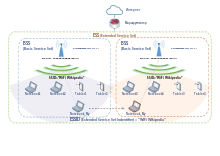
In IEEE 802.11 wireless local area networking standards (including Wi-Fi), a service set is a group of wireless network devices which share a service set identifier (SSID)—typically the natural language label that users see as a network name. (For example, all of the devices that together form and use a Wi‑Fi network called Foo are a service set.) A service set forms a logical network of nodes operating with shared link-layer networking parameters; they form one logical network segment.
A service set is either a basic service set (BSS) or an extended service set (ESS).
A basic service set is a subgroup, within a service set, of devices that share physical-layer medium access characteristics (e.g. radio frequency, modulation scheme, security settings) such that they are wirelessly networked. The basic service set is defined by a basic service set identifier (BSSID) shared by all devices within it. The BSSID is a 48-bit label that conform to MAC-48 conventions. While a device may have multiple BSSIDs, usually each BSSID is associated with at most one basic service set at a time.[1]
A basic service set should not be confused with the coverage area of an access point, known as the basic service area (BSA).[2]
Basic service set types[edit]
Infrastructure[edit]
An infrastructure BSS is created by an infrastructure device called an access point (AP) for other devices to join. (Note that the term IBSS is not used for this type of BSS but refers to the independent type discussed below.) The operating parameters of the infrastructure BSS are defined by the AP.[3] The Wi‑Fi segments of common home and business networks are examples of this type.
Each basic service set has a unique identifier, a BSSID, which is a 48-bit number that follows MAC address conventions.[4] An infrastructure BSSID is usually non-configurable, in which case it is either preset during manufacture or mathematically derived from a preset value such as a serial number or a MAC address of another network interface. As with the MAC addresses used for Ethernet devices, an infrastructure BSSID is a combination of a 24-bit organizationally unique identifier (OUI, the manufacturer’s identity) and a 24-bit serial number. A BSSID with a value of all 1s is used to indicate the wildcard BSSID, usable only during probe requests or for communications that take place outside the context of a BSS.[5]
Independent[edit]
An independent BSS (IBSS), or ad hoc network, is created by peer devices among themselves without network infrastructure.[6] A temporary network created by a cellular telephone to share its Internet access with other devices is a common example. In contrast to the stations in an infrastructure-mode network, the stations in a wireless ad hoc network communicate directly with one another, i.e. without a dependence on a distribution point to relay traffic between them.[7] In this form of peer-to-peer wireless networking, the peers form an independent basic service set (IBSS).[8] Some of the responsibilities of a distribution point—such as defining network parameters and other «beaconing» functions—are established by the first station in an ad-hoc network. But that station does not relay traffic between the other stations; instead, the peers communicate directly with one another. Like an infrastructure BSS, an independent-BSS also has a 48-bit MAC-address-like identifier. But unlike infrastructure BSS identifiers, independent-BSSs identifiers are not necessarily unique: the individual/group bit of the address is always set to 0 (individual), the universal/local bit of the address is always set to 1 (local), and the remaining 46 bits are randomly generated.[5]
Mesh[edit]
A mesh basic service set (MBSS) forms a self-contained network of mesh stations that share a mesh profile.[9] Each node may also be an access point hosting its own basic service set, for example using the mesh BSS to provide Internet access for local users. From the point of view of a wireless client, an IEEE 802.11s wireless mesh network appears as a conventional infrastructure mode topology, and is centrally configured as such. The formation of the mesh’s BSS, as well as wireless traffic management (including path selection and forwarding) is negotiated between the nodes of the mesh infrastructure. The mesh’s BSS is distinct from the networks (which may also be wireless) used by a mesh’s redistribution points to communicate with one another.
Service set identifier[edit]
The service set identifier (SSID) defines a service set or extends service set. Normally it is broadcast in the clear by stations in beacon packets to announce the presence of a network and seen by users as a wireless network name.
Unlike basic service set identifiers, SSIDs are usually customizable.[10] These SSIDs can be zero to 32 octets (32 bytes) long,[11] and are, for convenience, usually in a natural language, such as English. The 802.11 standards prior to the 2012 edition did not define any particular encoding or representation for SSIDs, which were expected to be treated and handled as an arbitrary sequence of 0–32 octets that are not limited to printable characters. IEEE Std 802.11-2012 defines a flag to express that the SSID is UTF-8-encoded and could contain any Unicode text.[12] Wireless network stacks must still be prepared to handle arbitrary values in the SSID field.
Since the contents of an SSID field are arbitrary, the 802.11 standard permits devices to advertise the presence of a wireless network with beacon packets in which the SSID field is set to null.[13][n 1] A null SSID (the SSID element’s ‘length’ field is set to zero[11]) is called a «wildcard SSID» in IEEE 802.11 standards documents,[14] and as a «no broadcast SSID» or «hidden SSID» in the context of beacon announcements,[13][15] and can be used, for example, in enterprise and mesh networks to steer a client to a particular (e.g. less utilized) access point.[13] A station may also likewise transmit packets in which the SSID field is set to null; this prompts an associated access point to send the station a list of supported SSIDs.[16] Once a device has associated with a basic service set, for efficiency, the SSID is not sent within packet headers; only BSSIDs are used for addressing.
Extended service set[edit]
An extended service set (ESS) is a wireless network, created by multiple access points, which appears to users as a single, seamless network, such as a network covering a home or office that is too large for reliable coverage by a single access point. It is a set of one or more infrastructure basic service sets on a common logical network segment (i.e. same IP subnet and VLAN).[17] Key to the concept is that the participating basic service sets appear as a single network[how?] to the logical link control layer.[17][18] Thus, from the perspective of the logical link control layer, stations within an ESS may communicate with one another, and mobile stations may move transparently from one participating basic service set to another (within the same ESS).[18] Extended service sets make possible distribution services such as centralized authentication. From the perspective of the link layer, all stations within an ESS are all on the same link, and transfer from one BSS to another is transparent to logical link control.[19]
The basic service sets formed in wireless ad hoc networks are, by definition, independent from other BSSs, and an independent BSS cannot therefore be part of an extended infrastructure.[20] In that formal sense an independent BSS has no extended service set. However, the network packets of both independent BSSs and infrastructure BSSs have a logical network service set identifier, and the logical link control does not distinguish between the use of that field to name an ESS network, and the use of that field to name a peer-to-peer ad hoc network. The two are effectively indistinguishable at the logical link control layer level.[19]
Notes[edit]
- ^ To associate with a wireless network, a station must know the network’s SSID. This information is either obtained from beacons broadcast by a base station (in which case a client can passively infer whether it is in range of that network), or—if no base station is advertising the SSID—a station must know the SSID beforehand by other means (e.g. from a previous configuration). When a client wishes to associate with a network, it sends the SSID in a probe request. An access point replies with a probe response if the SSID in a probe request is the wildcard SSID (SSID is zero-length) or matches an SSID that the access point supports;[14] otherwise the access point does not respond to the probe request.
References[edit]
- ^ «Understanding the Network Terms SSID, BSSID, and ESSID – Technical Documentation – Support – Juniper Networks». www.juniper.net.
- ^ IEEE Std 802.11-2007, § 3.15, p. 5.
- ^ IEEE Std 802.11-2012, § 4.10.3, pp. 84–88.
- ^ IEEE Std 802.11-2007, § 7.1.3.3, p. 6.
- ^ a b IEEE Std 802.11-2007, § 7.1.3.3.3, p. 65.
- ^ IEEE Std 802.11-2012, § 4.10.4, pp. 88–90.
- ^ IEEE Std 802.11-2007, § 5.6, p. 41.
- ^ IEEE Std 802.11-2007, § 5.21, p. 25.
- ^ IEEE Std 802.11-2012, § 3.1, p. 14.
- ^ Vasseur & Dunkels 2010, p. 432.
- ^ a b IEEE Std 802.11-2007, § 7.3.2.1, p. 101.
- ^ IEEE (2012). «Part 11: Wireless LAN Medium Access Control (MAC) and Physical Layer (PHY) Specifications Sponsored by the LAN/MAN Standards Committee». IEEE 802.11-2012: 562.
- ^ a b c Murty, et al 2008, p. 75.
- ^ a b IEEE Std 802.11-2007, § 11.1.3.2.1, p. 422.
- ^ Dornseif, et al 2002, p. 2.
- ^ Lindqvist, et al 2009, pp. 123f.
- ^ a b IEEE Std 802.11-2007, § 3.54, p. 8.
- ^ a b IEEE Std 802.11-2007, § 5.2.3.1, p. 26.
- ^ a b Edney 2004, p. 8.
- ^ IEEE Std 802.11-2007, § 5.6, p. 40.
Works cited[edit]
- Dornseif, Maximillian; Schumann, Kay H.; Klein, Christian (2002), «Tatsächliche und rechtliche Risiken drahtloser Computernetzwerke» (PDF), Datenschutz und Datensicherheit, 22 (4): 1–5.
- Edney, Jon (2004), «What is an ESS?», IEEE 802 LAN/MAN Standards Committee Meeting, July 2004, Piscataway, NJ: Institute of Electrical and Electronics Engineers.
- Lindqvist, Janne; Aura, Tuomas; Danezis, George; Koponen, Teemu; Myllyniemi, Annu; Mäki, Jussi; Roe, Michael (2009), «Privacy-preserving 802.11 Access-point Discovery», Proceedings of the Second ACM Conference on Wireless Network Security, WiSec ’09, New York: ACM, pp. 123–130, CiteSeerX 10.1.1.206.4148, doi:10.1145/1514274.1514293, ISBN 978-1-60558-460-7, S2CID 8509913.
- Murty, Rohan; Padhye, Jitendra; Chandra, Ranveer; Wolman, Alec; Zill, Brian (2008), «Designing High Performance Enterprise Wi-Fi Networks» (PDF), in Crowcroft, Jon; Dahlin, Mike; et al. (eds.), Proceedings of the 5th USENIX Symposium on Networked Systems Design and Implementation, NSDI ’08, Berkeley, CA: USENIX Association, pp. 73–88.
- Stacey, Robert; Ecclesine, Peter; et al., eds. (2010), «Wireless LAN Medium Access Control (MAC) and Physical Layer (PHY) Specifications, Amendment 6 (IEEE Std 802.11p-2010)» (PDF), Local and Metropolitan Area Networks, Specific Requirements, IEEE Standard for Information technology — Telecommunications and information exchange between systems, Piscataway, NJ: Institute of Electrical and Electronics Engineers, ISBN 978-0-7381-6324-6.
- Stephens, Adrian P.; Ecclesine, Peter, eds. (2012), «Wireless LAN Medium Access Control (MAC) and Physical Layer (PHY) Specifications (IEEE Std 802.11-2012)», Local and Metropolitan Area Networks, Specific Requirements, IEEE Standard for Information technology—Telecommunications and information exchange between systems, New York, NY: The Institute of Electrical and Electronics Engineers, Inc, ISBN 978-0-7381-7245-3.
- Cole, Terry L.; Barber, Simon, eds. (2007), «Wireless LAN Medium Access Control (MAC) and Physical Layer (PHY) Specifications (IEEE Std 802.11-2007)» (PDF), Local and Metropolitan Area Networks, Specific Requirements, IEEE Standard for Information technology— Telecommunications and information exchange between systems, Piscataway, NJ: Institute of Electrical and Electronics Engineers, ISBN 978-0-7381-5656-9.
- Vasseur, Jean-Philippe; Dunkels, Adam (2010), Interconnecting Smart Objects with IP: The Next Internet, Burlington, MA: Morgan Kaufmann, ISBN 978-0-12-375166-9.
Introduction
This documents describes the support of protocol 802.11v on a WLC (Wireless LAN controller).
Background Information
802.11v refers to the IEEE (Institute of Electrical and Electronics Engineers) 802.11 Wireless Network Management (Amendment 8).
Stations that supports WNM (Wireless network management) can exchange information with each other (Access Points and wireless clients) in order to improve their performance.
AireOS WLC version 8.1 or higher support these WNM services:
- Directed multicast service (DMS)
- BSS (Basic Service Set) Max idle period management
- BSS transition management
Directed multicast service (DMS):
Clients that supports DMS can request to the AP (Access Point) to send a multicast stream as unicast, like a dynamic media stream function.
For more information for media stream: VideoStream Deployment Guide
Without the use of DMS a client has to wake up every DTIM interval in order to receive multicast traffic. With DMS, the AP (Access Point) buffers the multicast traffic for certain client, when client wakes up it sends a unicast frame in order to request this traffic. It allows the client to sleep for a longer time and save battery power. Multicast frames are transmitted as unicast over the air, sent at a higher data rate than which It would have been used without DMS.
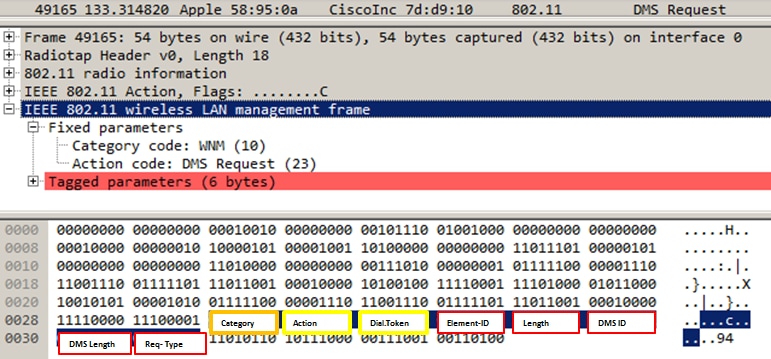
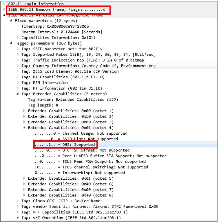
Wireless clients can send a DMS request-type Add frame in order to ask the AP to send as unicast the traffic of one or more specific multicast streams.
Management Frame — DMS Request type
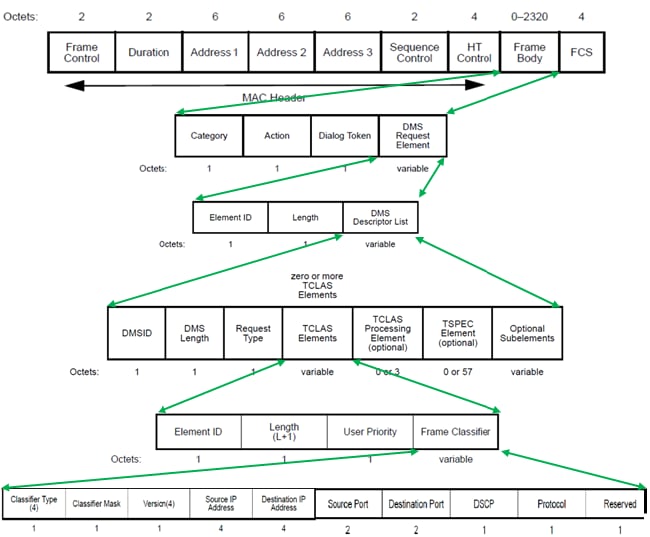
There are three types of DMS request:
| Description | Request type value |
| Add | 0 |
| Remove | 1 |
| Change | 2 |
| Reserved | 3-255 |
The DMS request-Add includes a DMS Descriptor.
Inside the DMS Descriptor List there is the TCLAS element, which specifies the multicast traffic stream that the wireless client requests to get as unicast. TCLAS specifies source/destination IP address, source/destination port besides other fields.
The AP sends these traffic streams as unicast to the wireless client and also it continues to send those streams as multicast to any other client in the network that does not support DMS.
Inside a DMS request frame there can be also a TSPEC element (optional), where the wireless client can define the QoS requirements and characteristics of a traffic flow.
Note: TSPEC is not supported
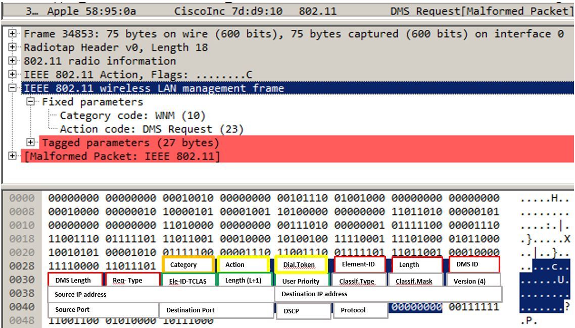
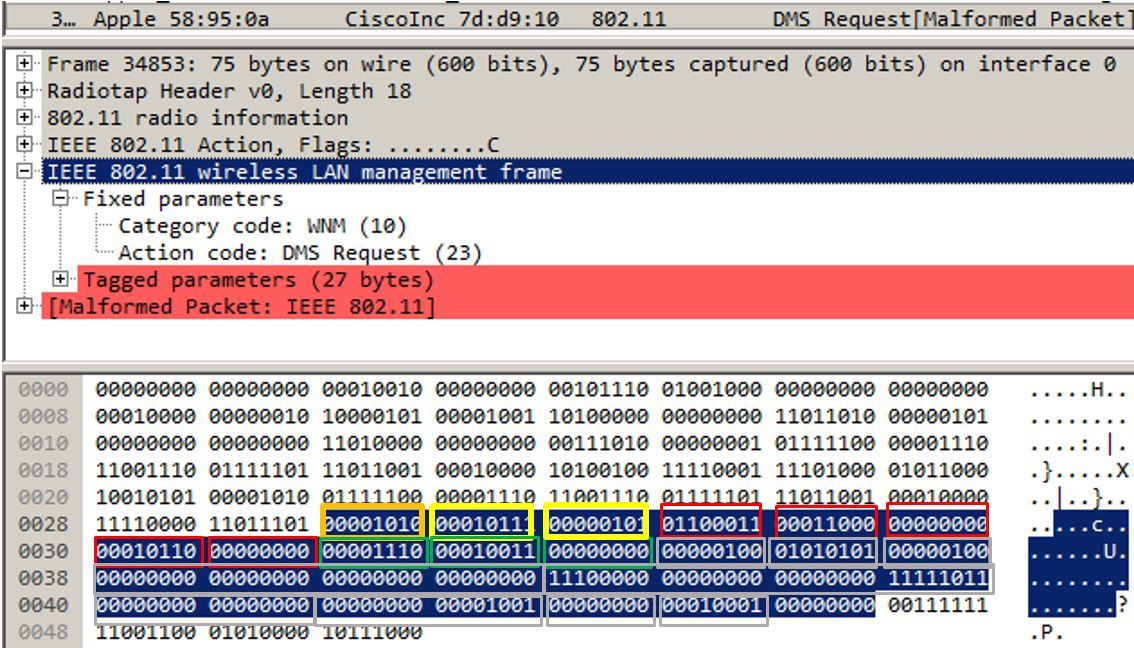
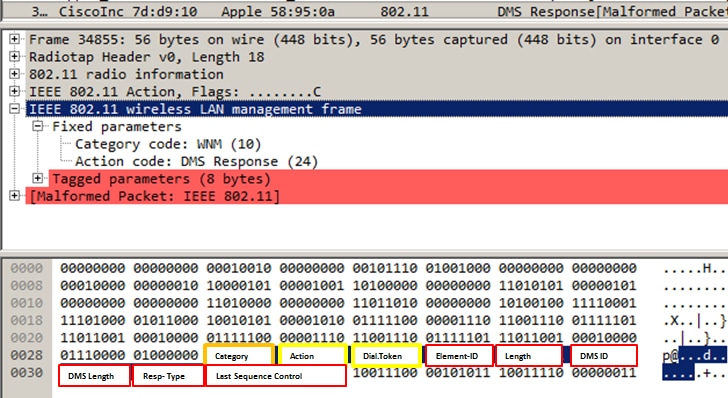
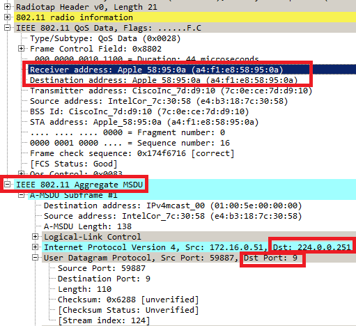
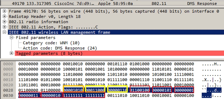
In this example the client sent a DMS request (Management frame, Category Code 10: WNM, Action code 23: DMS Request, for the multicast stream IPv4 on group 224.0.0.251, UDP (Protocol 17), destination port 9 (At this document wireshark is not able to completely decode a DMS request).
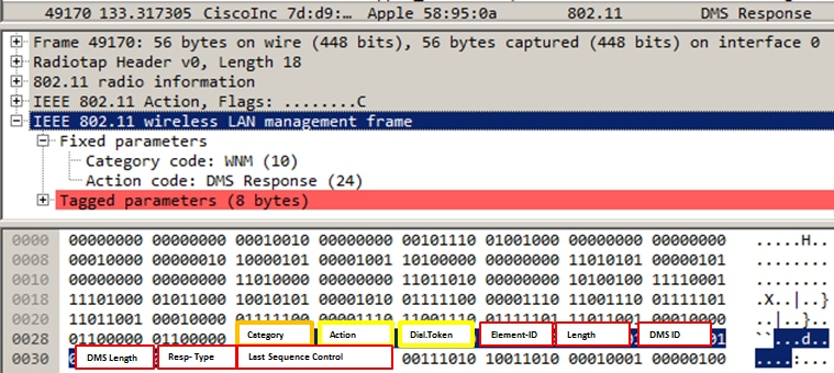
The AP answers the DMS request with a DMS response, which can be a DMS response-Accept or DMS Response-Deny.
If the AP sends a DMS response-Accept, it also assigns a DMSID to that communication flow.
DMS Request type Change can be used by the wireless client to modify an existent DMSID, for example to request a different TSPEC for a traffic flow.
Note: DMS change is not supported
Management Frame — DMS Response type
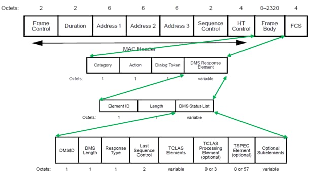
There are three DMS Response Types:
| Field Value | Description |
| 0 | Accept |
| 1 | Denied |
| 2 | Terminate |
| 3-255 | Reserved |
In this example the AP sent a DMS Response-Accept and it assigns a DMS ID 1 to the DMS request sent by the client.
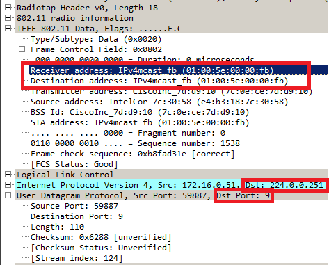
After that if there is a packet with destination group 224.0.0.251 on port 9 it is sent to the air as multicast and it is also buffered on the AP until the client that sent the DMS request is awake is available to receive it as unicast.
This is an example of a packet destination to group 224.0.0.251 on port 9 sent as regular multicast. Notice that the receiver and destination mac address refers to the multicast group.
This is an example of a frame sent as unicast to the client that sent the DMS request. Here the destination and receive address is the mac address of the client and not the multicast mac address. Also the multicast packet is sent as AMSDU.
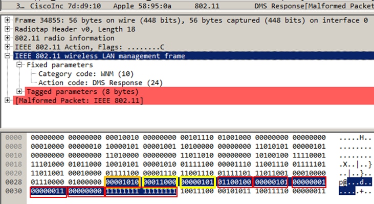
Once a wireless client no longer wants to receive a multicast stream as unicast it can send a new DMS request to close that flow, it uses the DMS ID that was assigned before by the AP. It is a DMS Request — Remove Type (1)
And the AP confirms this termination with a DMS Response Type Terminate (2)
BSS Max idle period:
When an AP no longer receives frames from a wireless client for a certain period of time it assumes the client left the network and it disassociates it. The BSS Max idle period is the amount of time an AP can keep a client associated without have to receive any frame (client can remain sleep). This value is informed to the wireless client through the association and re-association response frame. This allows the clients to remain asleep for a longer time and save battery power.
BSS Max idle period only appears in association-response or re-association response frames
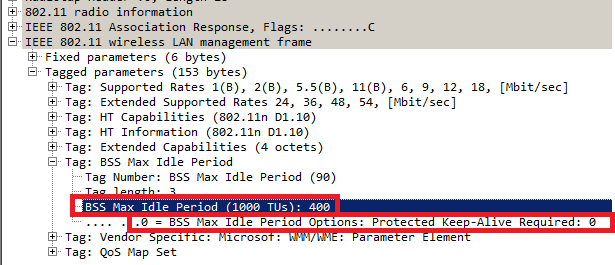
The BSS Max Idle Period is specified in units of 1000 TUs (Time units). Every time unit is equal to 1.024 milliseconds
Idle timeout = 1.024 x BSS Max Idle Period = X seconds
In the example frame:
Idle timeout = 1.024 x 405 = 414.72 seconds
If the Protected Keep-alive Required bit is set to 1, it means that the wireless client must send a RSN protected frame to the AP in order to reset the Idle Timer. If it is set to 0, as this example, the wireless client can send any type of frame (protected or unprotected) to reset the Idle timer at the AP.
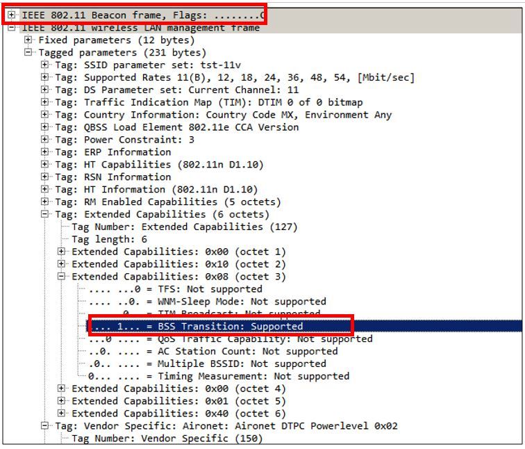
BSS transition management
802.11v BSS Transition Management Request is a suggestion given to client. Client can make its own decision whether to follow the suggestion or not. The disassociation of a client can be forced if disassociation-imminent function is enabled. It disassociates the client after a period of time if the client does not re-associate to one of the suggested APs.
802.11v BSS Transition is applied to these four scenarios:
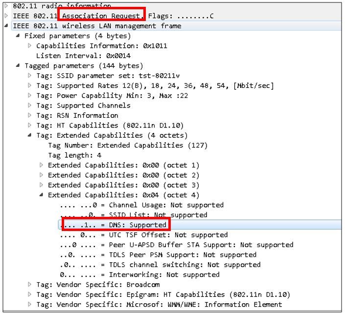
Solicited Request
Wireless client sends an 802.11v BSS Transition Management Query before they roam for a better option of APs to re-associate with.
Example of a 802.11v BSS Transition Management Query
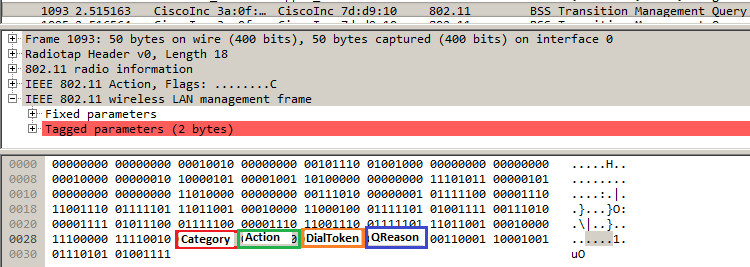
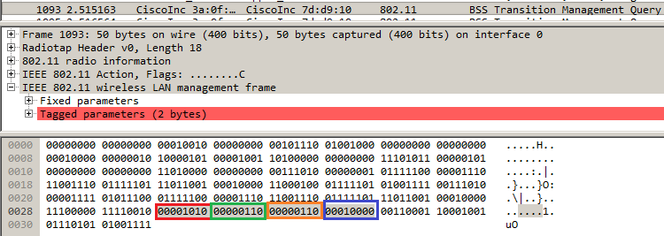
QReason means BSS Transition Query Reason, which is the reason why the client requests the candidate AP list. In this example the client sent a reason 16, which correspond to Low RSSI. For full list of transition query reasons consult Table 8-138 of IEEE 802.11-2012.
After the radio receives this frame, it responds with a BSS Transition Management Request in order to provide the AP candidate list.
Unsolicited Load Balance request
When WLC has load balance feature + BSS transition enabled, the AP no longer sends a deauthentication frame to a wireless client when it is heavily loaded, it sends a BSS transition management request in order to suggest the wireless client another less loaded AP.
For more information about load balance feature: Configuring Aggressive Load Balancing
Unsolicited Optimized Roaming request
When WLC has optimized roaming + BSS transition enabled, the AP no longer sends a deauthentication frame to a wireless client when the client does not meet the minimum RSSI (or any other parameter related to optimized roaming), it sends a BSS transition management in order to suggest the wireless client a better AP.
For more information about optimized roaming feature: Cisco Optimized Roaming
Client steer on FRA AP (Flexible Radio Assignment)
If a client connects to a less optimum cell within a FRA AP, AP sends out an 802.11v BSS transition Management Request to this client.
When an APs that supports FRA (like 2800 or 3800) uses only 5GHz, there are two cells (micro and macro cell). If a client connects to the macro-cell but micro-cell is more optimal (based on RSSI) then the AP sends a 802.11v BSS transition management request to the client in order to suggest to move the micro-cell and vice versa.
This feature is available since version 8.2.110.0.
For more information about FRA: Flexible Radio Assignment (FRA) and Redundant Radios
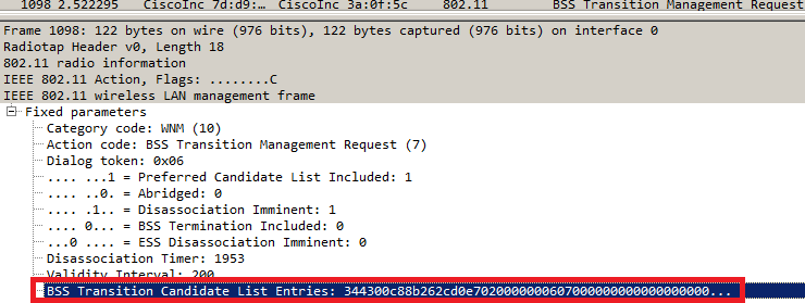
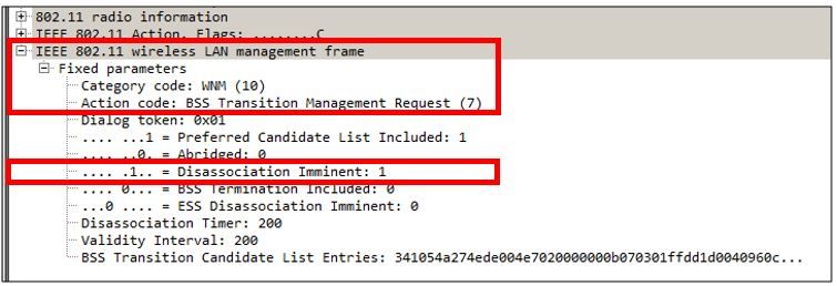
Disassociation Imminent
Within a BSS transition Management Request, Disassociation Imminent field can be added. This function is to disassociate the client after a period of time if the client does not re-associate to another AP.
When unsolicited optimized roaming request is triggered, the AP sends a BSS Transition Management Request to the client and wait for a certain period (time configured under Optimized Roaming Disassociation Timer), if the client does not roam to a better AP within that period of time, then the AP completes the disassociation of the client.
When Unsolicited Load Balance request is triggered, the AP sends a BSS Transition Management Request to the client and wait for a certain period (time configured under Disassociation Timer), if the client does not roam to a less congested AP within that period of time, then the AP completes the disassociation of the client.
Example of a BSS transition management frame with Disassociation imminent enabled:
BSS Transition Management Response
After a wireless cleint has received a BSS Transition Management Request, it can or cannot send a BSS Transition Management Response. If the client transitions to another AP it sends it with status code Accept, but if it plans to stay on the same AP due to several reasons it sends it with status code Reject plus the reason of rejection.
Example of a BSS Transition Management Response frame
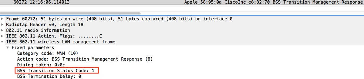
In this example the wireless client rejects the AP candidate list and does not roam to a different AP. The status code 1 shows the reason why the client leaves the ESS. For full list of status code definitions consult Table 8-253 of IEEE 802.11-2012.
Prerequisites
Requirements
In order to take advantage of 802.11v capabilities of a wlan it is needed to have wireless clients that supports 802.11v.
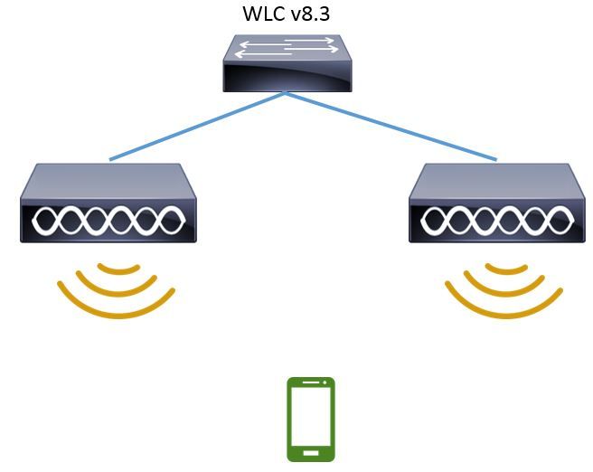
Components Used
WLC v8.3
Ipod Touch 6th Generation v10.1.1
Configure
Network Diagram
Configurations
Directed multicast service (DMS)
Configuration over WLAN to enable DMS:
CLI config:
> config wlan disable <wlan-id>
> config wlan dms enable <wlan-id>
> config wlan enable <wlan-id>
GUI config (available from version 8.3)
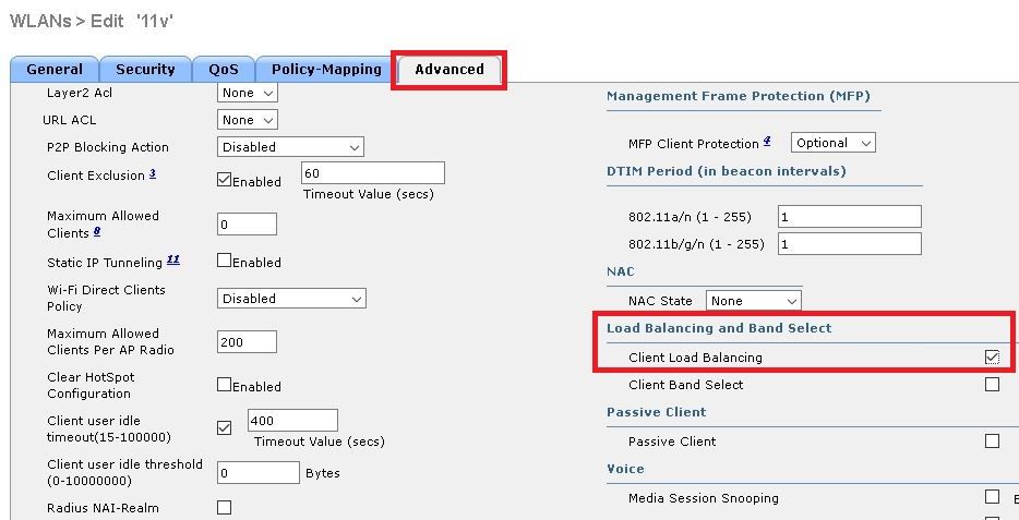
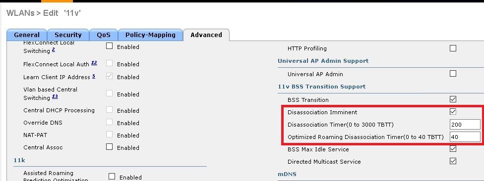
Step 1. Navigate to WLANs > Wlan-ID and click the WLAN to enable DMS.
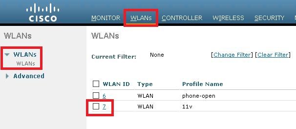
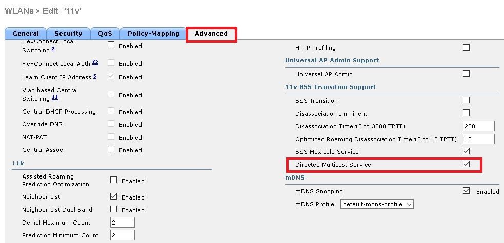
Step 2. Navigate to Advanced > 11v BSS Transition Support and enable Directed Multicast Service
BSS Max idle period management
Configuration over WLAN to enable BSS Max Idle period management:
CLI config:
> config wlan disable <wlan-id>
> config wlan bssmaxidle enable <wlan-id>
> config wlan usertimeout <seconds> <wlan-id>
> config wlan enable <wlan-id><seconds> Client Idle timeout(in seconds) on this WLAN. Range 0,15-100000 secs. 0 in order to disable
GUI config:
Step 1. Navigate to WLANs > WLAN-ID and click the WLAN to set the BSS Max idle period.

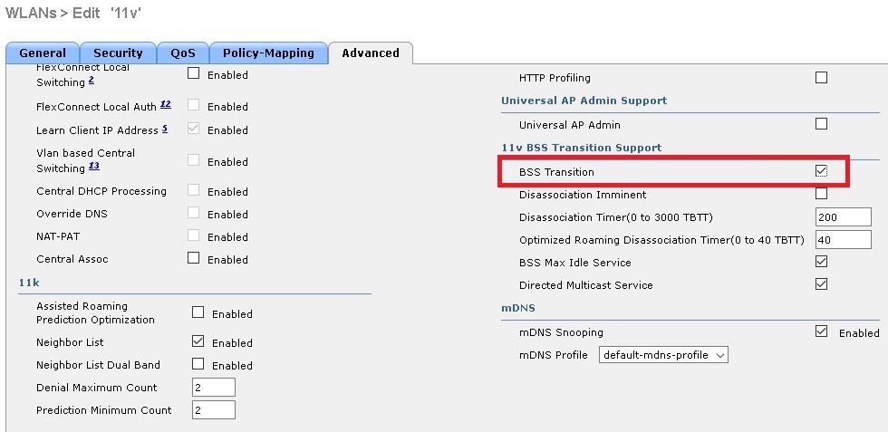
Step 2. Navigate to Advanced > 11v BSS Transition Support and enable BSS Max Idle Service.
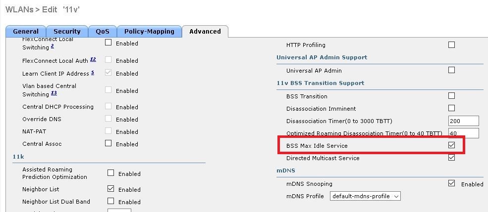
Note: This GUI options is introduced on version 8.3. For previous versions use command config wlan bssmaxidle enable <wlan-id>
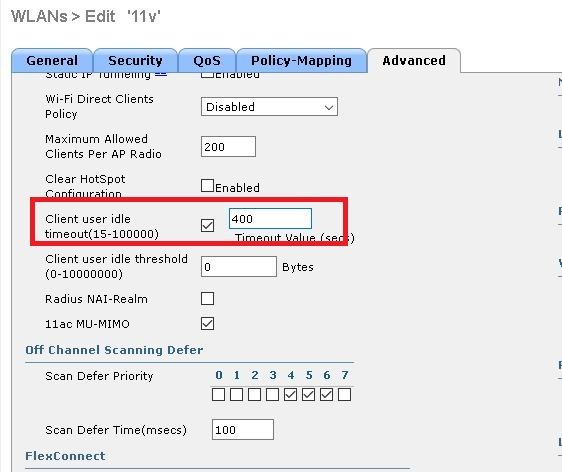
Step 3. Navigate to Advanced > Client User Idle timeout and set the timeout value in seconds.
BSS transition management
Configuration over WLAN to enable BSS transition management:
Note: If only BSS transition is enabled, the only way the Access Points sends BSS transition Management Request frames is if a wireless client sends a BSS Transition Management Query Frame.
Note: In order to make the APs to send BSS transition Management Request when they are heavily loaded It is needed to enable BSS transition + load balance.
Note: In order to make the APs to send BSS transition Management Request when a wireless client does not have the best RSSI, it is needed to enable BSS transition + optimized roaming.
Solicited request
CLI config:
> config wlan disable <wlan-id>
> config wlan bss-transition enable <wlan-id>
> config wlan enable <wlan-id>
GUI config:
Step 1. Navigate to WLANs > WLAN ID > Advanced and enable BSS Transition.

Unsolicited Load Balance request
CLI config:
> config wlan disable <wlan-id>
> config wlan bss-transition enable <wlan-id>
> config wlan load-balance allow enable <wlan-id>
> config wlan enable <wlan-id>
GUI config:
Step 1. Navigate to WLANs > WLAN ID > Advanced and enable BSS Transition and Client Load Balancing.

Unsolicited Optimized Roaming request
CLI config:
> config wlan disable <wlan-id>
> config wlan bss-transition enable <wlan-id>
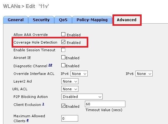
> config wlan chd <wlan-id> enable
> config wlan enable <wlan-id>
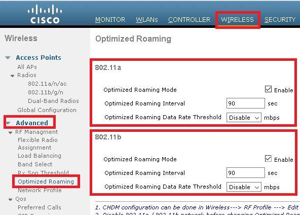
> config advanced { 802.11a | 802.11b } optimized-roaming enable
GUI config:
Step 1. Navigate to WLANs > WLAN ID > Advanced and enable BSS Transition and Coverage Hole Detection.
Step 2. Naviaget to WIRELESS > Advanced > Optimized Roaming and enable for both band Optimized Roaming Mode. For more information about Optimized Roaming parameters consult this document: High Density Experience (HDX) Deployment Guide, Release 8.0
Disassociation Imminent
CLI config:
> config wlan disable <wlan-id>
> config wlan bss-transition enable <wlan-id>
> config wlan disassociation-imminent enable <wlan-id>
> config wlan bss-transition disassociation-imminent oproam-timer <timer-in-TBTT> <WLAN id>
> config wlan bss-transition disassociation-imminent timer <timer-in-TBTT> <WLAN id>
> config wlan enable <wlan-id>
Step 1. Navigate to WLANs > WLAN ID > Advanced, enable BSS Transition, Disassociation Imminent and set Disassociation Timer and Optimized Roaming Disassociation Timer.
GUI config:

Note: Timers are specified in TBTT (Target Beacon Transmission Time) units, which is the interval time between every beacon. By default every beacon is sent every 100ms, so by default 1 TBTT = 100ms. Timers = X TBTT/10 = x seconds.
Verify
These images show the support of the WLAN (Wireless Local Area Network) and the wireless clients for the different 802.11v services.
SSID support
- DMS
- BSS transition management
Client support
- DMS
- BSS transition management
Debug client activity
In order to monitor 11v client activity these commands are available.
> debug client <mac-add-of-client>
> debug mac addr <mac-add-of-client>
> debug 11v all enable
Client with DMS capabilities
Client is 11v capable
*apfMsConnTask_0: Nov 01 22:55:27.577: a4:f1:e8:58:95:0a Association received from mobile on BSSID 7c:0e:ce:7d:d9:10 AP AP-3700-1
*apfMsConnTask_0: Nov 01 22:55:27.577: a4:f1:e8:58:95:0a Client is 11v BSS Transition capable
Client sends a DMS request for group 224.0.0.251 udp port 9 and the AP sends the DMS accept
*apfMsConnTask_0: Nov 01 22:56:43.928: a4:f1:e8:58:95:0a Got action frame from this client.
*apfMsConnTask_0: Nov 01 22:56:43.928: a4:f1:e8:58:95:0a Received a 11v Action Frame with code [23] from mobile station
*apfMsConnTask_0: Nov 01 22:56:43.928: Received 80211v_DMS_REQ Action Frame
*apfMsConnTask_0: Nov 01 22:56:43.928:  WLAN-id : 1 | vap_ip : 1
*apfMsConnTask_0: Nov 01 22:56:43.928: a4:f1:e8:58:95:0a Posting msg of type: APF_80211v_MSG_DMS_REQ for STA and LRAD:7c:0e:ce:7d:d9:10,slot:0, len:26
*apfMsConnTask_0: Nov 01 22:56:43.928: 11v g_msgQueue = 0x2b415828,            osapiMessageSend rc = 0
*apf80211vTask: Nov 01 22:56:43.929: Tclas found:
*apf80211vTask: Nov 01 22:56:43.929: [
*apf80211vTask: Nov 01 22:56:43.929: Version = 4,
*apf80211vTask: Nov 01 22:56:43.929: Destination IP = 224.0.0.251,
*apf80211vTask: Nov 01 22:56:43.929: Destination Port = 9,
*apf80211vTask: Nov 01 22:56:43.929: Protocol = 17,
*apf80211vTask: Nov 01 22:56:43.929: ]
*apf80211vTask: Nov 01 22:56:43.929: a4:f1:e8:58:95:0a New client  requesting DMS for this Tclas
*apf80211vTask: Nov 01 22:56:43.929: DMS Request IE processed: State: DMS_REQ_ADD_ACCEPTED
*apf80211vTask: Nov 01 22:56:43.929: DMS Response IE created.
*apf80211vTask: Nov 01 22:56:43.929: Element ID: 100, Length: 5
*apf80211vTask: Nov 01 22:56:43.929: DMS ID: 1, DMS Length: 3, Response Type: DMS_RESP_ACCEPT, Last Sequence Control: 65535
*apf80211vTask: Nov 01 22:56:43.929: dmsRequestState = DMS_REQ_ADD_ACCEPTED
*apf80211vTask: Nov 01 22:56:43.929: a4:f1:e8:58:95:0a apf80211vSendPacketToMs: 802.11v Action Frame sent successfully to wlc
*apf80211vTask: Nov 01 22:56:43.929: apf80211vDmsDB_AddSTA: New DMS Client: a4:f1:e8:58:95:0a created and added under DMS ID: 1
*apf80211vTask: Nov 01 22:56:43.929: a4:f1:e8:58:95:0a apfPostDmsClientRequestMsg: posting capwap for ms  lradmac7c:0e:ce:7d:d9:10
*apf80211vTask: Nov 01 22:56:43.929: 11v g_msgQueue = 0x2b415828,            osapiMessageSend rc = 0
*apf80211vTask: Nov 01 22:56:43.929: a4:f1:e8:58:95:0a apf80211vHandleDmsMsgSend: send capwap for STA  lradmac 7c:0e:ce:7d:d9:10
From the AP where the client is connected
AP# debug dot11 dot11v all

*Nov  1 22:51:04.323: DOT11v: Inside DMS ADD Operation
*Nov  1 22:51:04.323: DOT11v: TCLAS found in DMS DB
*Nov  1 22:51:04.323: DOT11v: New client detected
*Nov  1 22:51:04.323: DOT11v: Ref Cnt: 1
*Nov  1 22:51:04.323: DOT11v: Client A4:F1:E8:58:95:0A added to DMS DB Entry
*Nov  1 22:51:04.323: DOT11v: DMS Add Operation Succeeded
*Nov  1 22:51:04.323: Received and decoded a DMS client request payload SUCCESSFULLY
After that the client is added to the DMS database on the wlan. All the clients that send a DMS Request-Add for the same multicast string are listed under the same DMS ID.
> show wlan 1

WLAN Identifier.................................. 1
Profile Name..................................... 11v
Network Name (SSID).............................. 11v
Status........................................... Enabled
.
.
.
Number of active DMS Clients..................... 1
DMS ID 		 Client MAC Addresses
1 		  a4:f1:e8:58:95:0a
DMS Database is stored in the AP where this client is connected:
AP# show controllers dot11Radio { 0 | 1 } | beg Global DMS

   Global DMS - requests:2 uc:130 drop:0
   DMS enabled on WLAN(s): 11v
11v

    DMS database:
   Entry 1: mask=0x55 version=4 dstIp=0xE00000FB srcIp=0x00000000 dstPort=9 srcPort=0 dcsp=0 protocol=17
{Client, SSID}: {08:74:02:77:13:45, 11v}, {A4:F1:E8:58:95:0A, 11v},
Once the wireless client closes the DMS flow, it sends a DMS Request Remove
*apfMsConnTask_0: Nov 01 22:57:33.990: a4:f1:e8:58:95:0a Got action frame from this client.
*apfMsConnTask_0: Nov 01 22:57:33.990: a4:f1:e8:58:95:0a Received a 11v Action Frame with code [23] from mobile station
*apfMsConnTask_0: Nov 01 22:57:33.990: Received 80211v_DMS_REQ Action Frame
*apfMsConnTask_0: Nov 01 22:57:33.990:  WLAN-id : 1 | vap_ip : 1
*apfMsConnTask_0: Nov 01 22:57:33.990: a4:f1:e8:58:95:0a Posting msg of type: APF_80211v_MSG_DMS_REQ for STA and LRAD:7c:0e:ce:7d:d9:10,slot:0, len:5
*apfMsConnTask_0: Nov 01 22:57:33.990: 11v g_msgQueue = 0x2b415828,            osapiMessageSend rc = 0
*apf80211vTask: Nov 01 22:57:33.991: DMS Request IE processed: State: DMS_REQ_DEL_ACCEPTED
*apf80211vTask: Nov 01 22:57:33.991: DMS Response IE created.
*apf80211vTask: Nov 01 22:57:33.991: Element ID: 100, Length: 5
*apf80211vTask: Nov 01 22:57:33.991: DMS ID: 1, DMS Length: 3, Response Type: DMS_RESP_TERMINATE, Last Sequence Control: 65535
*apf80211vTask: Nov 01 22:57:33.991: dmsRequestState = DMS_REQ_DEL_ACCEPTED
*apf80211vTask: Nov 01 22:57:33.991: a4:f1:e8:58:95:0a apf80211vSendPacketToMs: 802.11v Action Frame sent successfully to wlc
*apf80211vTask: Nov 01 22:57:33.991: STA: a4:f1:e8:58:95:0a has dequeued and deleted from the DMS Entry with ID: 1
*apf80211vTask: Nov 01 22:57:33.991: apf80211vDmsDB_DeleteSTA: STA: a4:f1:e8:58:95:0a deleted successfully under DMS ID: 1
*apf80211vTask: Nov 01 22:57:33.991: a4:f1:e8:58:95:0a apfPostDmsClientRequestMsg: posting capwap for ms  lradmac7c:0e:ce:7d:d9:10

*apf80211vTask: Nov 01 22:57:33.991: 11v g_msgQueue = 0x2b415828,            osapiMessageSend rc = 0
From the AP
*Nov  1 22:57:33.167: DOT11v: Removing client A4:F1:E8:58:95:0A from DMS DB Entry
*Nov  1 22:57:33.167: DOT11v: DMS DB Delete Operation Succeeded
*Nov  1 22:57:33.167: Received and decoded a DMS client request payload SUCCESSFULLY
Client BSS Transition Capable
Client is 11v capable
*apfMsConnTask_3: Apr 12 10:46:36.239: 08:74:02:77:13:45 Association received from mobile on BSSID f0:7f:06:e8:32:76 AP AP-3700
*apfMsConnTask_3: Apr 12 10:46:36.239: 08:74:02:77:13:45 Client is 11v BSS Transition capable
Client sends a BSS Transition Management Query
*apfMsConnTask_1: Nov 14 05:40:32.857: c4:7d:4f:3a:0f:5c Got action frame from this client.
*apfMsConnTask_1: Nov 14 05:40:32.858: c4:7d:4f:3a:0f:5c Received a 11v Action Frame with code [6] from mobile station
*apfMsConnTask_1: Nov 14 05:40:32.858: Received 80211v_BSS_TRANS_QUERY Action Frame
*apfMsConnTask_1: Nov 14 05:40:32.859:  WLAN-id : 1 | vap_ip : 1
*apfMsConnTask_1: Nov 14 05:40:32.859: c4:7d:4f:3a:0f:5c Posting msg of type: APF_80211v_MSG_BSS_TRANS_QUERY for STA and LRAD:00:c8:8b:26:2c:d0,slot:0, len:1
*apf80211vTask: Nov 14 05:40:32.860: Session URL is not NULL
*apf80211vTask: Nov 14 05:40:32.860: Disassociation Imminent is 1
*apf80211vTask: Nov 14 05:40:32.860: Disassociation Timer is 200
*apf80211vTask: Nov 14 05:40:32.860: Building BSS Transition Request Frame
*apf80211vTask: Nov 14 05:40:32.860: Adding Neighbor List Subelement
*apfMsConnTask_1: Nov 14 05:40:32.861: 11v g_msgQueue = 0x2b415828,            osapiMessageSend rc = 0
*apf80211vTask: Nov 14 05:40:32.861: Location Info: 0,0,0 for BSSID: 7c:0e:ce:7d:d9:10
*apf80211vTask: Nov 14 05:40:32.861: Data Length of BSS Transition Request Frame: 73
*apf80211vTask: Nov 14 05:40:32.862: apf80211vHandleBSSTransQuery: lradMacAddr: 00:c8:8b:26:2c:d0 rscb parent MAC ADDR: 00:c8:8b:26:2c:d0 rscb mac address: 00:00:00:00:00:00
*apf80211vTask: Nov 14 05:40:32.862: 11v Action Frame sent:
*apf80211vTask: Nov 14 05:40:32.863: c4:7d:4f:3a:0f:5c apf80211vSendPacketToMs: 802.11v Action Frame sent successfully to wlc
*apf80211vTask: Nov 14 05:40:32.863: Successfully sent BSS Transition Request Action Frame to STA: c4:7d:4f:3a:0f:5c
As the wlan has enabled Disassociation Imminent, the client gets disassociated after the Disassociation timer is over
*apf80211vTask: Nov 14 05:40:32.863: c4:7d:4f:3a:0f:5c Setting Session Timeout to 20 sec - starting session timer for the mobile
*apf80211vTask: Nov 14 05:40:32.863: c4:7d:4f:3a:0f:5c Disassociate client in 20 seconds
*osapiBsnTimer: Nov 14 05:40:52.768: c4:7d:4f:3a:0f:5c Authentication session timer expired: mark mobile for immediate deletion
*osapiBsnTimer: Nov 14 05:40:52.768: c4:7d:4f:3a:0f:5c apfMsSessionExpireCallback (apf_ms.c:707) Expiring Mobile!
*apfReceiveTask: Nov 14 05:40:52.769: apfMsExpireMobileStation: Delete Immediately
*apfReceiveTask: Nov 14 05:40:52.769: c4:7d:4f:3a:0f:5c apfMsExpireMobileStation (apf_ms.c:7521) Changing state for mobile c4:7d:4f:3a:0f:5c on AP 00:c8:8b:26:2c:d0 from Associated to Disassociated
*apfReceiveTask: Nov 14 05:40:52.769: c4:7d:4f:3a:0f:5c apfSendDisAssocMsgDebug (apf_80211.c:3541) Changing state for mobile c4:7d:4f:3a:0f:5c on AP 00:c8:8b:26:2c:d0 from Disassociated to Disassociated
*apfReceiveTask: Nov 14 05:40:52.769: c4:7d:4f:3a:0f:5c Sent Disassociate to mobile on AP 00:c8:8b:26:2c:d0-0 (reason 1, caller apf_ms.c:7614)
*apfReceiveTask: Nov 14 05:40:52.769: c4:7d:4f:3a:0f:5c Sent Deauthenticate to mobile on BSSID 00:c8:8b:26:2c:d0 slot 0(caller apf_ms.c:7616)
*apfReceiveTask: Nov 14 05:40:52.769: c4:7d:4f:3a:0f:5c Setting active key cache index 8 ---> 8
*apfReceiveTask: Nov 14 05:40:52.769: c4:7d:4f:3a:0f:5c Deleting the PMK cache when de-authenticating the client.
*apfReceiveTask: Nov 14 05:40:52.769: Sent Deauthenticate to STA: c4:7d:4f:3a:0f:5c on BSSID: 00:c8:8b:26:2c:d0, slotId: 0, vapId: 1
AP sends BSS Transition Management Frame due to load balancing
*apfMsConnTask_3: Apr 12 10:47:18.785: 08:74:02:77:13:45 11v BSS Transition Request is posted to 11v queue.
*apf80211vTask: Apr 12 10:47:18.789: Session URL is not NULL
*apf80211vTask: Apr 12 10:47:18.789: Disassociation Imminent is 1
*apf80211vTask: Apr 12 10:47:18.789: Disassociation Timer is 200
*apf80211vTask: Apr 12 10:47:18.789: Building BSS Transition Request Frame
*apf80211vTask: Apr 12 10:47:18.789: Adding Neighbor List Subelement
*apf80211vTask: Apr 12 10:47:18.789: Data Length of BSS Transition Request Frame: 22
*apf80211vTask: Apr 12 10:47:18.789: apf80211vHandleBSSTransQuery: lradMacAddr: f0:7f:06:e8:32:70 rscb parent MAC ADDR: f0:7f:06:e8:32:70 rscb mac address: 00:00:00:00:00:00
*apf80211vTask: Apr 12 10:47:18.789: 11v Action Frame sent:
*apf80211vTask: Apr 12 10:47:18.790: 08:74:02:77:13:45 apf80211vSendPacketToMs: 802.11v Action Frame sent successfully to wlc
*apf80211vTask: Apr 12 10:47:18.790: Successfully sent BSS Transition Request Action Frame to STA: 08:74:02:77:13:45
AP sends BSS Trasnsition Management Frame due to optimized roaming
*apfMsConnTask_0: Nov 04 04:58:55.320: a4:f1:e8:58:95:0a Posting msg of type: APF_80211v_MSG_BSS_TRANS_QUERY for STA and LRAD:7c:0e:ce:7d:d9:10,slot:0, len:0
*apfMsConnTask_0: Nov 04 04:58:55.320: 11v g_msgQueue = 0x2b415828,            osapiMessageSend rc = 0
*apfMsConnTask_0: Nov 04 04:58:55.320: a4:f1:e8:58:95:0a 11v BSS Transition Request is posted to 11v queue.
*apf80211vTask: Nov 04 04:58:55.321: Session URL is not NULL
*apf80211vTask: Nov 04 04:58:55.321: Disassociation Imminent is 1
*apf80211vTask: Nov 04 04:58:55.321: Disassociation Timer is 40
*apf80211vTask: Nov 04 04:58:55.321: Building BSS Transition Request Frame
*apf80211vTask: Nov 04 04:58:55.321: Adding Neighbor List Subelement
*apf80211vTask: Nov 04 04:58:55.321: No Neighbor Candidate found :Resetting Candidate Included List
*apf80211vTask: Nov 04 04:58:55.321: Data Length of BSS Transition Request Frame: 4
*apf80211vTask: Nov 04 04:58:55.321: apf80211vHandleBSSTransQuery: lradMacAddr: 7c:0e:ce:7d:d9:10 rscb parent MAC ADDR: 7c:0e:ce:7d:d9:10 rscb mac address: 00:00:00:00:00:00
*apf80211vTask: Nov 04 04:58:55.322: 11v Action Frame sent:
*apf80211vTask: Nov 04 04:58:55.322: a4:f1:e8:58:95:0a apf80211vSendPacketToMs: 802.11v Action Frame sent successfully to wlc
*apf80211vTask: Nov 04 04:58:55.322: Successfully sent BSS Transition Request Action Frame to STA: a4:f1:e8:58:95:0a
*apf80211vTask: Nov 04 04:58:55.322: a4:f1:e8:58:95:0a Setting Session Timeout to 4 sec - starting session timer for the mobile
*apf80211vTask: Nov 04 04:58:55.322: a4:f1:e8:58:95:0a Disassociate client in 4 seconds
References
Chapter: 802.11r, 802.11k, 802.11v, 802.11w Fast Transition Roaming
IEEE Standard for Information technology—Telecommunications and information exchange between systems Local and metropolitan area networks—Specific requirements-Part 11: Wireless LAN Medium Access Control
(MAC) and Physical Layer (PHY) Specifications
Wi-Fi 6 или 802.11ax – самый новый из выпущенных на данный момент стандартов Wi-Fi. Увеличенная скорость, обновленный MIMO, Target Wake Time, BSS Coloring, работа в 2.4 и 5 ГГц. Про это и многое другое и будет рассказано в данной статье.

BSS Coloring
Что такое BSS Coloring и зачем он нужен? Для ответа на этот вопрос давайте разберем как работают сети Wi-Fi. Сначала, перед тем, как отправить данные, клиентское устройство слушает эфир и если он свободен, то отправляет точке доступа запрос на передачу информации, приняв который, точка отправляет клиенту разрешение, после чего и начинается передача данных. Если же эфир занят, то клиент берет паузу и через некоторое время пробует еще раз.
Проблема в том, что до Wi-Fi 6 данный механизм не различал свой-чужой – если кто-то передает (например, точка соседа), значит эфир занят и нужно ждать своей очереди. Соответственно падает скорость, а время ожидания увеличивается.
Для решения данной проблемы в 802.11ax была добавлена технология BSS Coloring, маркирующая пакеты с данными. Теперь, если при анализе сети устройство обнаруживает пакет с чужим кодом, то оно просто проигнорирует его, а значит – экономит время, что особенно будет заметно в местах с большим количеством беспроводных сетей.
OFDMA

Следующее важное новшество – поддержка OFDMA – множественного доступа с ортогональным частотным разделением каналов. Суть данной технологии заключается в том, что частотный канал разбивается на определенное количество поднесущих каналов меньшей ширины, каждый из которых используется для приема и передачи информации одному или нескольким клиентам одновременно.
На картинке выше – восемь поднесущих. В первый момент времени один из клиентов (красный) использует всю ширину канала, далее два клиента (красный и синий) в один момент времени передают или принимают данные, в следующей момент времени три клиента, потом один и т д. Ранее же, до 802.11ax, применялась технология OFDM, когда в один момент времени данные передавались только одному клиенту.
Более простыми словами суть OFDMA можно описать так: представим транспортную компанию, отправляющую каждому клиенту отдельный грузовик, независимо от размеров его посылки. Не очень эффективно, но именно так и работает OFDM, используемый в пятом и четвертом Wi-Fi. Что сделали в OFDMA? Запихнули все посылки в один грузовик и отправили всем клиентам, а они уже сами разбираются что кому предназначено.
1024QAM
Далее в 802.11ax была добавлена поддержка модуляции 1024QAM, что позволяет вместить еще больше информации в радиоволну. Если быть точнее, то переход с 256QAM (применяется в 802.11ac) на 1024QAM позволяет запихнуть на 25% больше информации. Из минусов – требование к качеству сигнала, ведь чем больше информации передается, тем больше вероятность ее потери при прохождении через преграды. Из-за этого она работает только при хорошем соотношении сигнал/шум (хорошем качестве сигнала).
Обновленный MU-MIMO
Впервые MU-MIMO появился в Wi-Fi 5 и позволял роутеру передавать данные нескольким клиентам одновременно. В технологии использовалось несколько пространственных потоков, количество которых зависело от количества антенн. Максимум, доступный в 802.11 ac – четыре потока, но только в одном направлении – от точки доступа к клиенту.
В Wi-Fi 6 пошли дальше и увеличили количество одновременных соединений до 8, а также позволили не только передавать, но и получать данные по данной технологии, т е в 802.11ax MU-MIMO работает и на прием, и на отправку.
Target Wake Time
Target Wake Time – еще одна технология, добавленная в Wi-Fi 6. Ее основное предназначение – использование в различных устройствах умного дома.
Target Wake Time позволяет девайсам определять когда и как часто они будут просыпаться чтобы получить или отправить информацию. По сути это позволяет увеличить время сна устройства (а значит и продлить время автономной работы от батарейки), а также определять время доступа к беспроводной среде, тем самым снижая на нее нагрузку.
2.4 ГГц
Убранный в пятой версии диапазон 2.4 ГГц вновь возвращается в Wi-Fi 6. Сети шестого поколения поддерживают сразу два частотных диапазона – 2.4 и 5 ГГц.
Устройства Wi-Fi 6

На данный момент все основные производители уже выпустили роутеры с поддержкой нового стандарта. Он есть у Huawei, TP-Link, Xiaomi, Asus и других популярных производителей.
Что касается клиентских устройств – Samsung добавил поддержку в Galaxy Note 10, Apple – в iPhone 11. В ряде смартфонов Huawei, OnePlus, Xiaomi, Sony и Asus так же имеется поддержка нового стандарта. Получить полный список смартфонов с поддержкой Wi-Fi 6 можно на Яндекс Маркете, поставив в фильтрах соответствующую галочку.
А что с умным домом? Тут пока ничего не поменялось. Все основные устройства – лампочки, бытовая техника, розетки и выключатели все так же продолжают выпускать с интерфейсом Wi-Fi 4.
Why do we need BSS Color mechanism?
Let us first understand the problem and then look into the need for BSS coloring.
1. Pre-802.11ax way (legacy mechanism):
“Every Wi-Fi device has to follow CSMA/CA method and if the whole physical channel is free then it can transmit any frame in the air, when others are waiting for the medium to be freed“. For detailed CSMA/CA explanation, here is the link: https://wifisharks.com/2020/10/31/csma-ca/
2. OBSS:
Now, the problem occurs when one BSS device can hear the transmission of other BSS device operating in same channel. This is overlapping of two BSSs, often called as OBSS (Overlapping Basic Service Set).This is also referred as co-channel interference (CSI) -> Collocated two same channels are interfering each other.
Example: One AP1 operating in channel 11 and nearby another AP2 is also operating in channel 11. Here is one basic picture to understand OBSS problem.
For CCA/CS (channel assessment/carrier sense) way,
AP2, STA2 cannot transmit if AP1 is doing some transmission.
AP1, STA1 cannot transmit if AP2 is doing some transmission.
If we can select some optimal BSS packet detect (OBSS PD) threshold, then BSS-1 can transmit simultaneously with BSS-2.
What’s is problem in OBSS and solutions?
OBSS reduces the overall performance of WLAN.
Solutions:
- A Quiet Element as specified in IEEE 802.11 (2007). In advertised Quiet Time, no can transmit in the same frequency. There are rarely any devices who supports this.
- BSS Coloring was originally introduced in 802.11ah. There is no devices with BSS coloring in pre-802.11ax devices. From 11ax devices a procedure called spatial reuse operation is enabled. As per IEEE standard, two independent spatial reuse modes are shared.
- OBSS PD-based.
- SRP-based.
Basic knowledge on BSS Color:
Ideally, If AP supports BSS color feature, then for every 802.11ax BSS is given a numerical value called BSS color. This value is an identifier for that BSS.A different BSS color value should be chosen for other BSS.
To understand further, we should know about “Intra-BSS” and “Inter-BSS”.
“Intra-BSS”: If a received frame BSS color is same as receiver’s BSS color then the received frame is from intra-BSS. So, receiver should defer its transmission if it wants transmit any frame. Suppose: STA1 and STA2 are connected to AP1 .BSS color is 5. STA1 wants to transmit and it has received a frame [which is from STA2] with BSS color 5. Then STA1 cannot transmit immediately as the frame is from its own BSS.
“Inter-BSS”: If a received frame BSS color is different from receiver’s BSS color then the received frame is from inter-BSS. So, receiver may not defer its transmission if it wants transmit any frame. Suppose: STA1 and STA2 are connected to AP1 .BSS color is 5. STA1 wants to transmit and it has received a frame [which is from STA3 from nearby BSS] with BSS color 6. Then STA1 may transmit as the frame is not from its own BSS.
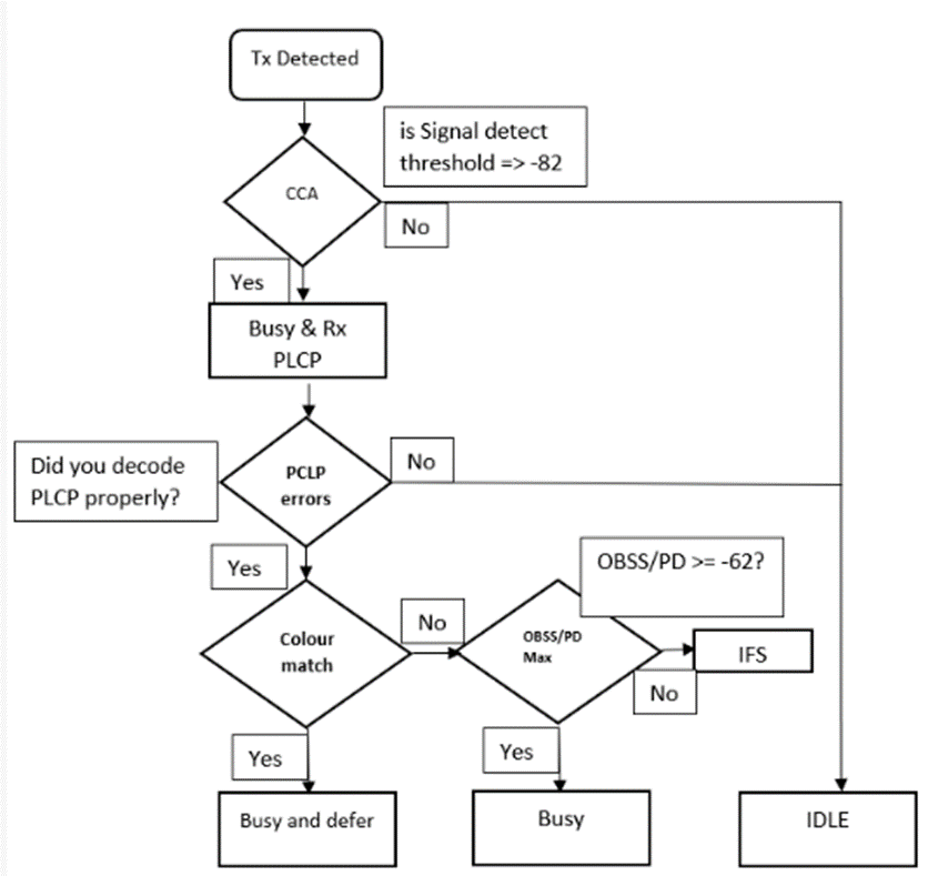
There are some other parameter along with BSS color check. Let us understand in more details from below flow chart.
BSS color with Spatial Reuse Operation (SRO):
SRO is the technic used by Wi-Fi6 devices to apply adaptive CCA for detected OBSS. Let us understand this from another flow diagram and simples steps.
- STA starts detecting RF energy.
- CCA points if energy threshold > -82dBm or below.
- If detected frame RSSI > -82dBm [RSSI > -82dBm means detected frame is having stronger signal than -82dBm] and station checks whether it can extract the traffic?
- If yes, read packet header to check the BSS color.
- If it’s same color, then its intra-BSS frame [same BSS frame] and will have to follow as usual CSMA/CA process.
- If detected frame BSS color is not same as own BSS color.
- Now, there is another RSSI threshold. If RSSI > -62dBm or RSSI < -62dBm.
- If RSSI > -62, then received frame station is too nearby and medium will be declared as busy.
- If RSSI < -62, then received frame station is too far, so STA will continue transmitting.
Will BSS color solve the co-channel interference (CCI) Problem?
It cannot solve completely. Some points to be remembered
- Legacy devices can not differentiate between BSS on same channel.
- It’s a real time challenge to implement adaptive SD threshold [min and max value] properly in 11ax devices. So, in short this will take time to mature.
BSS Color fields format:
BSS color field is present inside HE operation element .This is generally sent by AP.
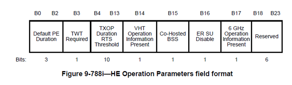
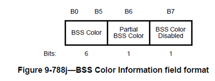
The BSS Color subfield value can be from 1 to 63.
The Partial BSS Color subfield = 1. This means an AID assignment rule depending on the BSS color.
The BSS Color Disabled subfield = 1. This indicates disable current BSS color.
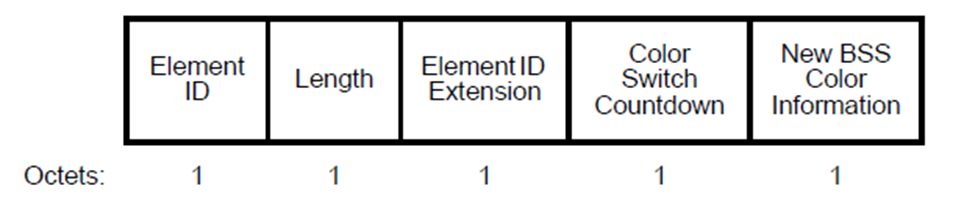
BSS Color Change Announcement element:
This is used by an AP to advertise new BSS color for the current BSS .This is an ACTION frame. This element may be carried in Beacon, Probe Response, (Re) Association Response frame.STA cannot send this frame.
BSS color collision event:
The report is sent by STA and it carries information about the BSS color used by OBSSs.
When AP can change BSS color?
- If AP detects OBSS AP also uses same BSS color.
- AP receives autonomous BSS color collision event reports from its associated STAs.
Conclusion:
In this article we have learned some basic overview of BSS color feature in 802.11ax. There are many more information on BSS color to learn in future.