Summary
Sub-menu: /ip arp
Even though IP packets are addressed using IP addresses, hardware addresses must be used to actually transport data from one host to another. Address Resolution Protocol is used to map OSI level 3 IP addresses to OSI level 2 MAC addresses. A router has a table of currently used ARP entries. Normally the table is built dynamically, but to increase network security, it can be partially or completely built statically by means of adding static entries.
Properties
This section describes the ARP table configuration options.
| Property | Description |
|---|---|
| address (IP; Default: ) | IP address to be mapped |
| interface (string; Default: ) | Interface name the IP address is assigned to |
| mac-address (MAC; Default: 00:00:00:00:00:00) | MAC address to be mapped to |
| published (yes | no; Default: no) | Static proxy-arp entry for individual IP addresses. When an ARP query is received for the specific IP address, the device will respond with its own MAC address. No need to set proxy-arp on the interface itself for all the MAC addresses to be proxied. The interface will respond to an ARP request only when the device has an active route towards the destination |
Read-only properties:
| Property | Description |
|---|---|
| dhcp (yes | no) | Whether the ARP entry is added by DHCP server |
| dynamic (yes | no) | Whether the entry is dynamically created |
| invalid (yes | no) | Whether the entry is not valid |
The default maximum number of ARP entries depends on the installed amount of RAM. It can be adjusted with the command «/ip settings set max-neighbor-entries=x», see more details on IPv4 Settings.
ARP Modes
It is possible to set several ARP modes on the interface configuration.
disabled— the interface will not use ARPenabled— the interface will use ARPlocal-proxy-arp— the router performs proxy ARP on the interface and sends replies to the same interfaceproxy-arp— the router performs proxy ARP on the interface and sends replies to other interfacesreply-only— the interface will only reply to requests originated from matching IP address/MAC address combinations which are entered as static entries in the IP/ARP table. No dynamic entries will be automatically stored in the IP/ARP table. Therefore for communications to be successful, a valid static entry must already exist.
Disabled
If the ARP feature is turned off on the interface, i.e., arp=disabled is used, ARP requests from clients are not answered by the router. Therefore, a static ARP entry should be added to the clients as well. For example, the router’s IP and MAC addresses should be added to the Windows workstations using the arp command:
C:\> arp -s 10.5.8.254 00-aa-00-62-c6-09
Enabled
This mode is enabled by default on all interfaces. ARPs will be discovered automatically and new dynamic entries will be added to the ARP table.
Proxy ARP
A router with a properly configured proxy ARP feature acts as a transparent ARP proxy between different networks.
This behavior can be useful, for example, if you want to assign dial-in (ppp, pppoe, pptp) clients’ IP addresses from the same address space as used on the connected LAN.
Proxy ARP can be enabled on each interface individually with command arp=proxy-arp:
Setup proxy ARP:
 [admin@MikroTik] /interface ethernet> set 1 arp=proxy-arp

 [admin@MikroTik] /interface ethernet> print

 Flags: X - disabled, R - running
   #    NAME                 MTU   MAC-ADDRESS         ARP
   0  R ether1              1500  00:30:4F:0B:7B:C1 enabled
   1  R ether2              1500  00:30:4F:06:62:12 proxy-arp
Reply Only
If ARP property is set to reply-only on the interface, then the router only replies to ARP requests. Neighbour MAC addresses will be resolved only using statically configured entries from the «/ip arp» menu, but there will be no need to add the router’s MAC address to other hosts’ ARP tables like in case if ARP is disabled.
Local Proxy Arp
If the ARP property is set to local-proxy-arp on an interface, then the router performs proxy ARP to/from this interface only. i.e. for traffic that comes in and goes out of the same interface. In a normal LAN, the default behavior is for two network hosts to communicate directly with each other, without involving the router.
With local-proxy-arp enabled, the router will respond to all client hosts with the router’s own interface MAC address instead of the other host’s MAC address.
E.g. If Host A (192.168.88.2/24) queries for the MAC address of Host B (192.168.88.3/24), the router would respond with its own MAC address. In other words, if local-proxy-arp is enabled, the router would assume responsibility for forwarding traffic between Host A 192.168.88.2 and Host B 192.168.88.3. All the ARP cache entries on Hosts A and B will reference the router’s MAC address. In this case, the router is performing local-proxy-arp for the entire subnet 192.168.88.0/24.
An example for RouterOS local-proxy-arp could be a bridge setup with a DHCP server and isolated bridge ports where hosts from the same subnet can reach each other only at Layer3 through bridge IP.
/interface bridge
add arp=local-proxy-arp name=bridge1
/interface bridge port
add bridge=bridge1 horizon=1 interface=ether2
add bridge=bridge1 horizon=1 interface=ether3
add bridge=bridge1 horizon=1 interface=ether4
Gratuitous ARP
It is possible to create Gratuitous ARP requests in RouterOS. To do so you must use the Traffic-Generator tool, below is an example of how to generate a Gratuitous ARP request to update the ARP table on a remote device:
/tool traffic-generator inject interface=ether2 \
data="ffffffffffff4c5e0c14ef78080600010800060400014c5e0c14ef780a057a01ffffffffffff0a057a01000000000000000000000000000000000000"
You must change the MAC address (4c5e0c14ef78) and the IP address (0a057a01) to your router’s address. The IP address and the MAC address must be from the device that requests an ARP table update. You also need to specify through which interface (ether2) you want to send the Gratuitous ARP request. Make sure that receiving device supports Gratuitous ARP requests.
Address Resolution Protocol
The Address Resolution Protocol (ARP) feature performs a required function in IP routing. ARP finds the hardware address,
also known as Media Access Control (MAC) address, of a host from its known IP address. ARP maintains a cache (table) in which
MAC addresses are mapped to IP addresses. ARP is part of all Cisco systems that run IP.
This feature module explains ARP for IP routing and the optional ARP features you can configure, such as static ARP entries,
timeout for dynamic ARP entries, clearing the cache, and proxy ARP.
Information About the Address Resolution Protocol
Layer 2 and Layer 3 Addressing
IP addressing occurs at Layer 2 (data link) and Layer 3 (network) of the Open System Interconnection (OSI) reference model.
OSI is an architectural network model developed by ISO and ITU-T that consists of seven layers, each of which specifies particular
network functions such as addressing, flow control, error control, encapsulation, and reliable message transfer.
Layer 2 addresses are used for local transmissions between devices that are directly connected. Layer 3 addresses are used
for indirectly connected devices in an internetwork environment. Each network uses addressing to identify and group devices
so that transmissions can be sent and received. Ethernet (802.2, 802.3, Ethernet II, and Subnetwork Access Protocol [SNAP]),
Token Ring, and Fiber Distributed Data Interface (FDDI) use media access control (MAC) addresses that are “burned in” to the
network interface card (NIC). The most commonly used network types are Ethernet II and SNAP.

Note |
For the supported interface types, see the data sheet for your hardware platform. |
In order for devices to be able to communicate with each when they are not part of the same network, the 48-bit MAC address
must be mapped to an IP address. Some of the Layer 3 protocols used to perform the mapping are:
-
Address Resolution Protocol (ARP)
-
Reverse ARP (RARP)
-
Serial Line ARP (SLARP)
-
Inverse ARP
For the purposes of IP mapping, Ethernet, Token Ring, and FDDI frames contain the destination and source addresses. Frame
Relay and Asynchronous Transfer Mode (ATM) networks, which are packet-switched, data packets take different routes to reach
the same destination. At the receiving end, the packet is reassembled in the correct order.
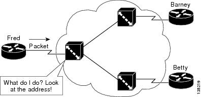
In a Frame Relay network, there is one physical link that has many logical circuits called virtual circuits (VCs). The address
field in the frame contains a data-link connection identifier (DLCI), which identifies each VC. For example, in the figure
below, the Frame Relay switch to which device Fred is connected receives frames; the switch forwards the frames to either
Barney or Betty based on the DLCI that identifies each VC. So Fred has one physical connection but multiple logical connections.
ATM networks use point-to-point serial links with the High-Level Data Link Control (HDLC) protocol. HDLC includes a meaningless
address field included in five bytes of the frame header frame with the recipient implied since there can be only one.
Overview of the Address Resolution Protocol
The Address Resolution Protocol (ARP) was developed to enable communications on an internetwork and is defined by RFC 826.
Layer 3 devices need ARP to map IP network addresses to MAC hardware addresses so that IP packets can be sent across networks.
Before a device sends a datagram to another device, it looks in its ARP cache to see if there is a MAC address and corresponding
IP address for the destination device. If there is no entry, the source device sends a broadcast message to every device on
the network. Each device compares the IP address to its own. Only the device with the matching IP address replies to the sending
device with a packet containing the MAC address for the device (except in the case of “proxy ARP”). The source device adds
the destination device MAC address to its ARP table for future reference, creates a data-link header and trailer that encapsulates
the packet, and proceeds to transfer the data. The figure below illustrates the ARP broadcast and response process.

When the destination device lies on a remote network, one beyond another Layer 3 device, the process is the same except that
the sending device sends an ARP request for the MAC address of the default gateway. After the address is resolved and the
default gateway receives the packet, the default gateway broadcasts the destination IP address over the networks connected
to it. The Layer 3 device on the destination device network uses ARP to obtain the MAC address of the destination device and
delivers the packet.
Encapsulation of IP datagrams and ARP requests and replies on IEEE 802 networks other than Ethernet use Subnetwork Access
Protocol (SNAP).
The ARP request message has the following fields:
-
HLN—Hardware address length. Specifies how long the hardware addresses are in the message. For IEEE 802 MAC addresses (Ethernet)
the value is 6. -
PLN—Protocol address length. Specifies how long the protocol (Layer 3) addresses are in the message. For IPv4, the value
is 4. -
OP—Opcode. Specifies the nature of the message by code: - 1—ARP request.
- 2—ARP reply.
- 3 through 9—RARP and Inverse ARP requests and replies.
-
SHA—Sender hardware address. Specifies the Layer 2 hardware address of the device sending the message.
-
SPA—Sender protocol address. Specifies the IP address of the sending device.
-
THA—Target hardware address. Specifies the Layer 2 hardware address of the receiving device.
-
TPA—Target protocol address. Specifies the IP address of the receiving device.
ARP Caching
Because the mapping of IP addresses to media access control (MAC) addresses occurs at each hop (Layer 3 device) on the network
for every datagram sent over an internetwork, performance of the network could be compromised. To minimize broadcasts and
limit wasteful use of network resources, Address Resolution Protocol (ARP) caching was implemented.
ARP caching is the method of storing network addresses and the associated data-link addresses in memory for a period of time
as the addresses are learned. This minimizes the use of valuable network resources to broadcast for the same address each
time a datagram is sent. The cache entries must be maintained because the information could become outdated, so it is critical
that the cache entries are set to expire periodically. Every device on a network updates its tables as addresses are broadcast.
There are static ARP cache entries and dynamic ARP cache entries. Static entries are manually configured and kept in the
cache table on a permanent basis. Static entries are best for devices that have to communicate with other devices usually
in the same network on a regular basis. Dynamic entries are added by Cisco software, kept for a period of time, and then removed.
Static and Dynamic Entries in the ARP Cache
Static routing requires an administrator to manually enter IP addresses, subnet masks, gateways, and corresponding media
access control (MAC) addresses for each interface of each device into a table. Static routing enables more control but requires
more work to maintain the table. The table must be updated each time routes are added or changed.
Dynamic routing uses protocols that enable the devices in a network to exchange routing table information with each other.
The table is built and changed automatically. No administrative tasks are needed unless a time limit is added, so dynamic
routing is more efficient than static routing. The default time limit is 4 hours. If the network has a great many routes that
are added and deleted from the cache, the time limit should be adjusted.
of this document.
|
Note |
The Cisco IOS XE does not install the ARPs and forward entries instantaneously. So, there will be some delay in the installation |
Devices That Do Not Use ARP
When a network is divided into two segments, a bridge joins the segments and filters traffic to each segment based on Media
Access Control (MAC) addresses. The bridge builds its own address table, which uses MAC addresses only, as opposed to a router,
which has an Address Resolution Protocol (ARP) cache that contains both IP addresses and the corresponding MAC addresses.
Passive hubs are central-connection devices that physically connect other devices in a network. They send messages out all
ports to the devices and operate at Layer 1, but they do not maintain an address table.
Layer 2 switches determine which port is connected to a device to which the message is addressed and send the message only
to that port, unlike a hub, which sends the message out all its ports. However, Layer 3 switches are routers that build an
ARP cache (table).
Inverse ARP
Inverse ARP, which is enabled by default in ATM networks, builds an ATM map entry and is necessary to send unicast packets
to a server (or relay agent) on the other end of a connection. Inverse ARP is supported only for the
aal5snap encapsulation type.
For multipoint interfaces, an IP address can be acquired using other encapsulation types because broadcast packets are used.
However, unicast packets to the other end will fail because there is no ATM map entry and thus DHCP renewals and releases
also fail.
For more information about Inverse ARP and ATM networks, see the “Configuring ATM” feature module in the
Asynchronous Transfer Mode Configuration Guide.
Reverse ARP
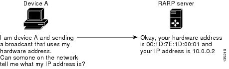
Reverse ARP (RARP) as defined by RFC 903 works the same way as the Address Resolution Protocol (ARP), except that the RARP
request packet requests an IP address instead of a media access control (MAC) address. RARP often is used by diskless workstations
because this type of device has no way to store IP addresses to use when they boot. The only address that is known is the
MAC address because it is burned in to the hardware.
RARP requires a RARP server on the same network segment as the device interface. The figure below illustrates how RARP works.
Because of the limitations with RARP, most businesses use Dynamic Host Configuration Protocol (DHCP) to assign IP addresses
dynamically. DHCP is cost-effective and requires less maintenance than RARP. The most important limitations with RARP are
as follows:
-
Because RARP uses hardware addresses, if the internetwork is large with many physical networks, a RARP server must be on every
segment with an additional server for redundancy. Maintaining two servers for every segment is costly. -
Each server must be configured with a table of static mappings between the hardware addresses and the IP addresses. Maintenance
of the IP addresses is difficult. -
RARP only provides IP addresses of the hosts but not subnet masks or default gateways.
Cisco software attempts to use RARP if it does not know the IP address of an interface at startup to respond to RARP requests
that it is able to answer. The AutoInstall feature of the software automates the configuration of Cisco devices.
AutoInstall supports RARP and enables a network manager to connect a new device to a network, turn it on, and automatically
load a pre-existing configuration file. The process begins when no valid configuration file is found in NVRAM. For more information
about AutoInstall, see the
Configuration Fundamentals Configuration Guide.
Proxy ARP
Proxy Address Resolution Protocol, as defined in RFC 1027, was implemented to enable devices that are separated into physical
network segments connected by a router in the same IP network or subnetwork to resolve IP-to-MAC addresses. When devices are
not in the same data link layer network but are in the same IP network, they try to transmit data to each other as if they
were on the local network. However, the router that separates the devices will not send a broadcast message because routers
do not pass hardware-layer broadcasts. Therefore, the addresses cannot be resolved.
Proxy ARP is enabled by default so the “proxy router” that resides between the local networks responds with its MAC address
as if it were the router to which the broadcast is addressed. When the sending device receives the MAC address of the proxy
router, it sends the datagram to the proxy router, which in turns sends the datagram to the designated device.
Proxy ARP is invoked by the following conditions:
-
The target IP address is not on the same physical network (LAN) on which the request is received.
-
The networking device has one or more routes to the target IP address.
-
All of the routes to the target IP address go through interfaces other than the one on which the request is received.
When proxy ARP is disabled, a device responds to ARP requests received on its interface only if the target IP address is
the same as its IP address or if the target IP address in the ARP request has a statically configured ARP alias.
Serial Line Address Resolution Protocol
Serial Line ARP (SLARP) is used for serial interfaces that use High-Level Data Link Control (HDLC) encapsulation. A SLARP
server, intermediate (staging) device, and another device providing a SLARP service might be required in addition to a TFTP
server. If an interface is not directly connected to a server, the staging device is required to forward the address-resolution
requests to the server. Otherwise, a directly connected device with SLARP service is required. Cisco software attempts to
use SLARP if it does not know the IP address of an interface at startup to respond to SLARP requests that software is able
to answer.
Cisco software automates the configuration of Cisco devices with the AutoInstall feature. AutoInstall supports SLARP and
enables a network manager to connect a new device to a network, turn it on, and automatically load a pre-existing configuration
file. The process begins when no valid configuration file is found in NVRAM. For more information about AutoInstall, see the
Configuration Fundamentals Configuration Guide.
|
Note |
AutoInstall supports serial interfaces that use Frame Relay encapsulation. |
Authorized ARP
Authorized ARP addresses a requirement of explicitly knowing when a user has logged off, either voluntarily or due to a failure
of a network device. It is implemented for Public wireless LANs (WLANs) and DHCP. For more information about authorized ARP,
refer to the “Configuring DHCP Services for Accounting and Security” chapter of the DHCP Configuration Guide
, Cisco IOS Release 12.4.
Security (ARP/NDP cache entries) Enhancements
The Security (ARP/NDP cache entries) Enhancements feature implements ARP
global limit and ARP interface limit. You can set a limit on the dynamic ARP
entries per interface. Using the Security (ARP/NDP cache entries) Enhancements
feature you can set a limit at either global level or interface level.
Interface level configuration overrides the value of global limit when set.
When the interface limit is not set, the global limit value is applied if the
global limit is configured. When you disable interface-limit on an interface,
you must execute the
no arp entries interface-limit command to enable the
interface-limit.
How to Configure the Address Resolution Protocol
By default, the Address Resolution Protocol (ARP) feature is enabled and is set to use Ethernet encapsulation. Perform the
following tasks to change or verify ARP functionality:
Enabling the Interface Encapsulation
Perform this task to support a type of encapsulation for a specific network, such as Ethernet, Frame Relay, FDDI, or Token
Ring. When Frame Relay encapsulation is specified, the interface is configured for a Frame Relay subnetwork with one physical
link that has many logical circuits called virtual circuits (VCs). The address field in the frame contains a data-link connection
identifier (DLCI) that identifies each VC. When SNAP encapsulation is specified, the interface is configured for FDDI or Token
Ring networks.
|
Note |
The encapsulation type specified in this task should match the encapsulation type specified in the “Defining Static ARP Entries” |
SUMMARY STEPS
-
enable
-
configure terminal
-
interface
type number -
arp {arpa |
frame-relay |
snap} -
end
DETAILED STEPS
| Command or Action | Purpose | |
|---|---|---|
|
Step 1 |
Example: |
Enables privileged EXEC mode.
|
|
Step 2 |
Example: |
Enters global configuration mode. |
|
Step 3 |
Example: |
Enters interface configuration mode. |
|
Step 4 |
Example: |
Specifies the encapsulation type for an interface by type of network, such as Ethernet, FDDI, Frame Relay, and Token Ring.
|
|
Step 5 |
Example: |
Returns to privileged EXEC mode. |
Defining Static ARP Entries
Perform this task to define static mapping between an IP address (32-bit address) and a Media Access Control (MAC) address
(48-bit address) for hosts that do not support dynamic Address Resolution Protocol (ARP). Because most hosts support dynamic
address resolution, defining static ARP cache entries is usually not required. Performing this task installs a permanent entry
in the ARP cache that never times out. The entries remain in the ARP table until they are removed using the
no arp command or the
clear arp interface command for each interface.
|
Note |
The encapsulation type specified in this task should match the encapsulation type specified in the “Enabling the Interface |
SUMMARY STEPS
-
enable
-
configure terminal
-
arp {ip-address |
vrf
vrf-name}
hardware-address
encap-type [interface-type] -
end
DETAILED STEPS
| Command or Action | Purpose | |||
|---|---|---|---|---|
|
Step 1 |
Example: |
Enables privileged EXEC mode.
|
||
|
Step 2 |
Example: |
Enters global configuration mode. |
||
|
Step 3 |
Example: |
Globally associates an IP address with a MAC address in the ARP cache.
|
||
|
Step 4 |
Example: |
Returns to privileged EXEC mode. |
Setting an Expiration Time
for Dynamic Entries in the ARP Cache
SUMMARY STEPS
-
enable -
configure
terminal
-
interface
type
number -
arp
timeout
seconds -
end
DETAILED STEPS
| Command or Action | Purpose | |||
|---|---|---|---|---|
|
Step 1 |
Example: |
Enables
|
||
|
Step 2 |
Example: |
Enters global |
||
|
Step 3 |
Example: |
Enters |
||
|
Step 4 |
Example: |
Sets the The general recommended value for ARP timeout is the configured
|
||
|
Step 5 |
Example: |
Returns to |
Globally Disabling Proxy ARP
Proxy Address Resolution Protocol (ARP) is enabled by default; perform this task to globally disable proxy ARP on all interfaces.
The Cisco software uses proxy ARP (as defined in RFC 1027) to help hosts with no knowledge of routing determine the media
access control (MAC) addresses of hosts on other networks or subnets. For example, if hosts A and B are on different physical
networks, host B does not receive the ARP broadcast request from host A and cannot respond to it. However, if the physical
network of host A is connected by a gateway to the physical network of host B, the gateway sees the ARP request from host
A.
Assuming that subnet numbers were assigned to correspond to physical networks, the gateway can also tell that the request
is for a host that is on a different physical network. The gateway can then respond for host B, saying that the network address
for host B is that of the gateway itself. Host A sees this reply, caches it, and sends future IP packets for host B to the
gateway.
The gateway forwards such packets to host B by using the configured IP routing protocols. The gateway is also referred to
as a transparent subnet gateway or ARP subnet gateway.
SUMMARY STEPS
-
enable
-
configure terminal
-
ip arp proxy disable
-
end
DETAILED STEPS
| Command or Action | Purpose | |
|---|---|---|
|
Step 1 |
Example: |
Enables privileged EXEC mode.
|
|
Step 2 |
Example: |
Enters global configuration mode. |
|
Step 3 |
Example: |
Disables proxy ARP on all interfaces.
|
|
Step 4 |
Example: |
Returns to privileged EXEC mode. |
Disabling Proxy ARP on an Interface
Proxy Address Resolution Protocol (ARP) is enabled by default; perform this task to disable proxy ARP on an interface.
SUMMARY STEPS
-
enable
-
configure terminal
-
interface
type number -
no ip proxy-arp
-
end
DETAILED STEPS
| Command or Action | Purpose | |
|---|---|---|
|
Step 1 |
Example: |
Enables privileged EXEC mode.
|
|
Step 2 |
Example: |
Enters global configuration mode. |
|
Step 3 |
Example: |
Enters interface configuration mode. |
|
Step 4 |
no ip proxy-arp Example: |
Disables proxy ARP on the interface.
|
|
Step 5 |
Example: |
Returns to privileged EXEC mode. |
Clearing the ARP Cache
Perform the following tasks to clear the Address Resolution Protocol (ARP) cache of entries associated with an interface
and to clear all dynamic entries from the ARP cache, the fast-switching cache, and the IP route cache.
SUMMARY STEPS
-
enable
-
clear arp interface
type number -
clear arp-cache
-
exit
DETAILED STEPS
| Command or Action | Purpose | |
|---|---|---|
|
Step 1 |
Example: |
Enables privileged EXEC mode.
|
|
Step 2 |
Example: |
Clears the entire ARP cache on the interface. |
|
Step 3 |
clear arp-cache Example: |
Clears all dynamic entries from the ARP cache, the fast-switching cache, and the IP route cache. |
|
Step 4 |
Example: |
Returns to user EXEC mode. |
Configuring Security (ARP/NDP cache entries) Enhancements
enable
configure terminal
 arp entries interface-limit 1 log 1
 end
enable
configure terminal
 interface Ethernet 0/0
    ip address 1.1.1.40 255.255.255.0
    arp entries interface-limit 1 log 1
    end
enable
configure terminal
 interface Ethernet 0/1
    ip address 2.1.1.1 255.255.255.0
    arp entries interface-limit disable
    end
Verifying the ARP Configuration
To verify the ARP configuration, perform the following steps.
SUMMARY STEPS
-
show
interfaces
-
show
arp
-
show
ip
arp
-
show
processes
cpu
|
include
(ARP|PID)
DETAILED STEPS
|
Step 1 |
To display the type of ARP being used on a particular interface and also display the ARP timeout value, use the show interfaces EXEC command. Example: |
|
Step 2 |
Use the show arp EXEC command to examine the contents of the ARP cache. Example: |
|
Step 3 |
Use the show ip arp EXEC command to show IP entries. To remove all nonstatic entries from the ARP cache, use the clear arp-cache privileged EXEC command. Example: |
|
Step 4 |
Use the show processes cpu | include (ARP|PID) command to display ARP and RARP processes. Example: |
Configuration Examples for the Address Resolution Protocol
Example: Static ARP Entry Configuration
The following example shows how to configure a static Address Resolution Protocol (ARP) entry in the cache by using the
alias keyword, allowing the software to respond to ARP requests as if it were the interface of the specified address:
arp 10.0.0.0 aabb.cc03.8200 alias
interface gigabitethernet0/0/0
Example: Encapsulation Type Configuration
The following example shows how to configure the encapsulation on the interface. The
arpa keyword indicates that interface is connected to an Ethernet 802.3 network:
interface gigabitethernet0/0/0
 ip address 10.108.10.1 255.255.255.0
 arp arpa
Example: Proxy ARP Configuration
The following example shows how to configure proxy ARP because it was disabled for the interface:
interface gigabitethernet0/0/0
 ip proxy-arp
Examples: Clearing the ARP Cache
The following example shows how to clear all entries in the ARP cache associated with an interface:
Device# clear arp interface gigabitethernet0/0/0
The following example shows how to clear all dynamic entries in the ARP cache:
Device# clear arp-cache
Additional References
Related Documents
|
Related Topic |
Document Title |
|---|---|
|
Cisco IOS commands |
Cisco IOS Master Command List, All Releases |
|
ARP commands |
Cisco IOS IP Addressing Services Command Reference |
|
AppleTalk addressing scheme |
Core Competence AppleTalk (white paper) at www.corecom.com/html/appletalk.html |
|
Authorized ARP |
“Configuring DHCP Services for Accounting and Security” feature module in the |
|
Inverse ARP and ATM networks |
“Configuring ATM” feature module in the |
|
AutoInstall |
Configuration Fundamentals Configuration Guide |
RFCs
|
RFCs |
Title |
|---|---|
|
RFC 826 |
Address Resolution Protocol |
|
RFC 903 |
Reverse Address Resolution Protocol |
|
RFC 1027 |
Proxy Address Resolution Protocol |
|
RFC 1042 |
Standard for the Transmission of IP Datagrams over IEEE 802 Networks |
Technical Assistance
|
Description |
Link |
|---|---|
|
The Cisco Support and Documentation website provides online resources to download documentation, software, and tools. Use |
http://www.cisco.com/cisco/web/support/index.html |
Feature Information for the
Address Resolution Protocol
The following table provides release information about the feature or features described in this module. This table lists
only the software release that introduced support for a given feature in a given software release train. Unless noted otherwise,
subsequent releases of that software release train also support that feature.
Use Cisco Feature Navigator to find information about platform support and Cisco software image support. To access Cisco
Feature Navigator, go to www.cisco.com/go/cfn. An account on Cisco.com is not required.
|
Feature |
Software |
Feature |
|---|---|---|
|
Address |
The Address |
|
|
Security |
Cisco IOS |
The Security The |
Каждый сетевой инженер знает, как провести простейшую диагностику удаленного хоста: проверить приходят ли арпы, пингуется ли ip-адрес. «Арпы» — это записи с данным IP-адресом в ARP-таблице оборудования, на которое стучится проверяющий. Если её нет, то итог может быть печален – физически канал подключен, а логика не настроена, в следствие чего мак-адрес не резолвится. Если тебе понятно хотя бы два слова их двух последних предложений — ты не безнадежен
ARP (Address Resolution Protocol, RFC 826) — протокол для определения соответствия между логическим адресом сетевого уровня (IP) и физическим адресом устройства (MAC). Сама связь между двумя устройствами в сети проходит именно на канальном уровне (куда и относятся мак-адреса).
Протокол ARP имеет буфер, где и хранится пара IP-адрес — MAC-адрес. Эта информация заносится в т.н. ARP-таблицу. Она служит, чтобы устройства не тратили лишний трафик на очередную идентификацию — это снижает драгоценные миллисекунды при передаче данных. Кстати, в интернете до сих пор нет единого мнения на каком уровне работает APR — на втором (ethernet) или на третьем (ip).
Многие называют его протоколом «2,5 уровня»: ARP должен работать поверх уровня ethernet (это условие выполняется), но поверх ARP должен работать хотя бы один протокол сетевого уровня. Однако в ARP не инкапсулируется ни один из протоколов третьего уровня модели OSI. Таким образом получается подобие уровня 2.5, что-то среднее между канальным и сетевым.
Что за ARP-таблица?
APR-таблица представляет собой…таблицу. В ней всего два основных столбца — айпишник и мак. В то же время, в зависимости от устройства и запроса она будет содержать другие данные (динамика/статика), интерфейс, ip адрес источника (отправителя) и т.д. Например, ARP-таблица на коммутаторе Dlink выглядит так:
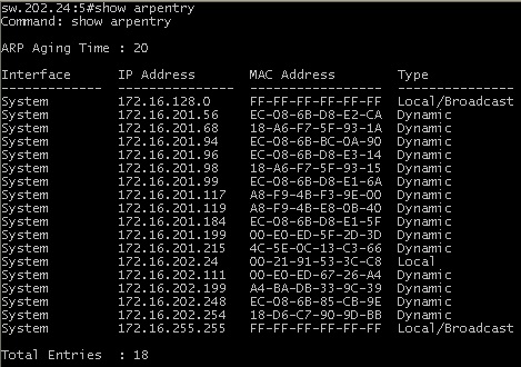
Здесь можно обратить внимание на широковещательный адрес (broadcast). Поле «адрес назначения Ethernet» заполняется единицами (ff:ff:ff:ff:ff:ff). Коммутатор, получив такой широковещательный фрейм, отправляет его всем компьютерам сети, как бы обращаясь ко всем с вопросом: «если Вы владелец этого ip адреса (ip адреса назначения), пожалуйста сообщите мне Ваш mac адрес».
Как это работает?
Как туда попадают эти записи? Суть в том, что IP-пакет создается с IP-адресом источника и назначения. Сам этот пакет будет инкапсулирован в кадр Ethernet с MAC-адресом источника и назначения. Окей, свой-то мак-адрес устройство знает. А как ему узнать мак-адрес получателя, чтобы пальнуть в него этим ethernet-кадром? Для этого и существует потокол ARP
IP-протокол (это уже третий, сетевой уровень модели OSI) проверяет есть ли в ARP-таблице принимающей стороны запись об этом устройстве (который отправляет запрос). Если запись существует — начинается передача пакетов. Если нет — отправляется широковещательный ARP-запрос, который выясняет, какому из устройств принадлежит IP-адрес. Протокол ARP опрашивает все хосты в локальной сети и только один отвечает на этот запрос
Один из хостов, которые получили этот широковещательный пакет, видит, что IP-адрес принадлежит ему. И в ответ шлет свой MAC-адрес. Соответственно запись связки IP-MAC заносится в ARP-таблицу. В следующий раз, понятное дело, это операция (для конкретного устройства с этим IP) уже не понадобится.
Наглядно:
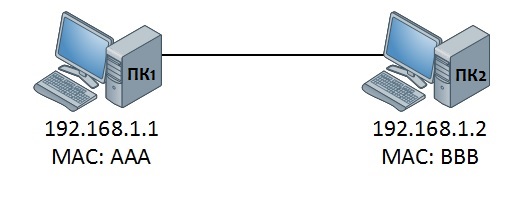
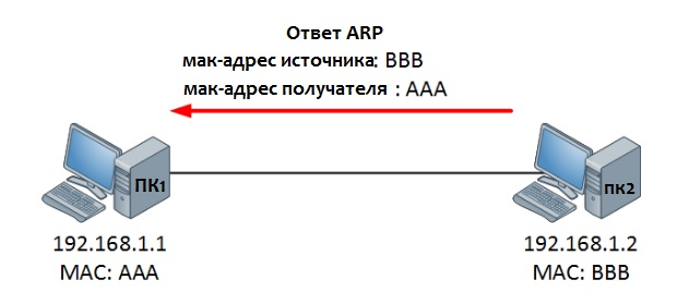
Итак. у нас есть два ПК1 и ПК2. Придумаем им IP и MAC-адрес
Давайте из ПК1 запустим команду Ping
ping 192.168.1.2
Pinging 192.168.1.2 with 32 bytes of data:
Reply from 192.168.1.2: bytes=32 time=15ms TTL=57
Reply from 192.168.1.2: bytes=32 time=15ms TTL=57
Reply from 192.168.1.2: bytes=32 time=14ms TTL=57
Reply from 192.168.1.2: bytes=32 time=17ms TTL=57
Ping statistics for 192.168.1.2:
Packets: Sent = 4, Received = 4, Lost = 0 (0% loss),
Approximate round trip times in milli-seconds:
Minimum = 14ms, Maximum = 17ms, Average = 15ms
Немного разберём команду. Ping использует протокол ICMP — сетевой протокол из стэка протоколов TCP/IP. Наш сформированный пакет IP-пакет будет иметь исходный IP-адрес ПК1 (192.168.1.1) и IP-адрес назначения ПК2 (192.168.1.2). Дальше мы инкапуслируем IP-пакет в кадр Ethernet . В этом кадре мы уже устанавливаем MAC-адреса: исходный ПК1 (AAA) и целевой ПК2 (BBB).
Это всё здорово, но как ping узнал мак-адрес получателя? Ведь изначально таблица ARP пуста, да и ICMP — протокол сетевой, не канальный. А узнал он его с помощью ARP
Итак, компьютер понимает, что он не знает MAC-адрес компьютера, доступность которого надо проверить. Для этого отправляется широковещательный пакет, о котором мы писали выше. Это сообщение достигнет всех компьютеров в сети
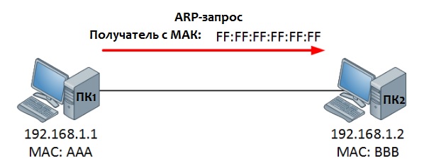
ПК видит, что этот IP принадлежит ему и ответит сообщением ARP Reply — «Это я! И это мой MAC-адрес». Теперь ПК1 может добавить MAC-адрес в свою таблицу ARP и начать пересылку данных в сторону ПК2.
Это очень краткое и поверхностное изложение протокола ARP — далеко не все аспекты работы лежат на поверхности. Дальше — самостоятельная работа. Stay Tuned!
The Address Resolution Protocol (ARP) is a communication protocol used for discovering the link layer address, such as a MAC address, associated with a given internet layer address, typically an IPv4 address. This mapping is a critical function in the Internet protocol suite. ARP was defined in 1982 by RFC 826,[1] which is Internet Standard STD 37.
ARP has been implemented with many combinations of network and data link layer technologies, such as IPv4, Chaosnet, DECnet and Xerox PARC Universal Packet (PUP) using IEEE 802 standards, FDDI, X.25, Frame Relay and Asynchronous Transfer Mode (ATM).
In Internet Protocol Version 6 (IPv6) networks, the functionality of ARP is provided by the Neighbor Discovery Protocol (NDP).
Operating scope
Edit
The Address Resolution Protocol is a request-response protocol. Its messages are directly encapsulated by a link layer protocol. It is communicated within the boundaries of a single network, never routed across internetworking nodes.
Packet structure
Edit
The Address Resolution Protocol uses a simple message format containing one address resolution request or response. The packets are carried at the data link layer of the underlying network as raw payload. In the case of Ethernet, a 0x0806 EtherType value is used to identify ARP frames.
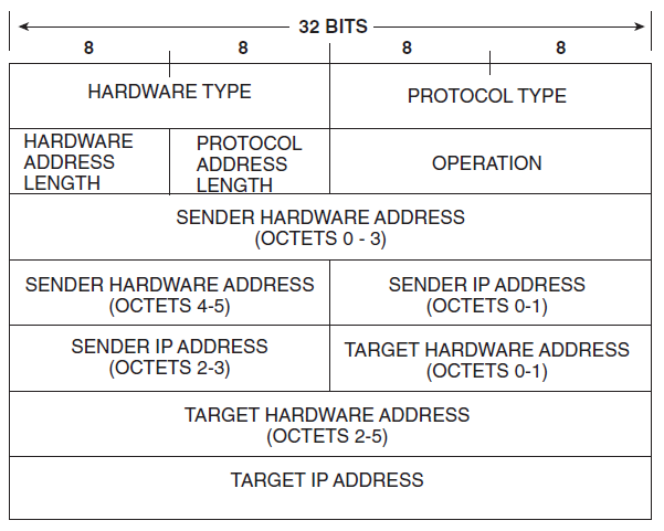
The size of the ARP message depends on the link layer and network layer address sizes. The message header specifies the types of network in use at each layer as well as the size of addresses of each. The message header is completed with the operation code for request (1) and reply (2). The payload of the packet consists of four addresses, the hardware and protocol address of the sender and receiver hosts.
The principal packet structure of ARP packets is shown in the following table which illustrates the case of IPv4 networks running on Ethernet. In this scenario, the packet has 48-bit fields for the sender hardware address (SHA) and target hardware address (THA), and 32-bit fields for the corresponding sender and target protocol addresses (SPA and TPA). The ARP packet size in this case is 28 bytes.
| Octet offset | 0 | 1 |
|---|---|---|
| 0 | Hardware type (HTYPE) | |
| 2 | Protocol type (PTYPE) | |
| 4 | Hardware address length (HLEN) | Protocol address length (PLEN) |
| 6 | Operation (OPER) | |
| 8 | Sender hardware address (SHA) (first 2 bytes) | |
| 10 | (next 2 bytes) | |
| 12 | (last 2 bytes) | |
| 14 | Sender protocol address (SPA) (first 2 bytes) | |
| 16 | (last 2 bytes) | |
| 18 | Target hardware address (THA) (first 2 bytes) | |
| 20 | (next 2 bytes) | |
| 22 | (last 2 bytes) | |
| 24 | Target protocol address (TPA) (first 2 bytes) | |
| 26 | (last 2 bytes) |
- Hardware type (HTYPE)
- This field specifies the network link protocol type. Example: Ethernet is 1.[2]
- Protocol type (PTYPE)
- This field specifies the internetwork protocol for which the ARP request is intended. For IPv4, this has the value 0x0800. The permitted PTYPE values share a numbering space with those for EtherType.[2][3]
- Hardware length (HLEN)
- Length (in octets) of a hardware address. Ethernet address length is 6.
- Protocol length (PLEN)
- Length (in octets) of internetwork addresses. The internetwork protocol is specified in PTYPE. Example: IPv4 address length is 4.
- Operation
- Specifies the operation that the sender is performing: 1 for request, 2 for reply.
- Sender hardware address (SHA)
- Media address of the sender. In an ARP request this field is used to indicate the address of the host sending the request. In an ARP reply this field is used to indicate the address of the host that the request was looking for.
- Sender protocol address (SPA)
- Internetwork address of the sender.
- Target hardware address (THA)
- Media address of the intended receiver. In an ARP request this field is ignored. In an ARP reply this field is used to indicate the address of the host that originated the ARP request.
- Target protocol address (TPA)
- Internetwork address of the intended receiver.
ARP protocol parameter values have been standardized and are maintained by the Internet Assigned Numbers Authority (IANA).[2]
The EtherType for ARP is 0x0806. This appears in the Ethernet frame header when the payload is an ARP packet and is not to be confused with PTYPE, which appears within this encapsulated ARP packet.
Layering
Edit
ARP’s placement within the Internet protocol suite and the OSI model may be a matter of confusion or even of dispute. RFC 826 places it into the Link Layer and characterizes it as a tool to inquire about the «higher level layer», such as the Internet layer.[4] RFC 1122 also discusses ARP in its link layer section.[5]
Richard Stevens places ARP in OSI’s data link layer[6] while newer editions associate it with the network layer or introduce an intermediate OSI layer 2.5.[7]
Example
Edit
Two computers in an office (Computer 1 and Computer 2) are connected to each other in a local area network by Ethernet cables and network switches, with no intervening gateways or routers. Computer 1 has a packet to send to Computer 2. Through DNS, it determines that Computer 2 has the IP address 192.168.0.55.
To send the message, it also requires Computer 2‘s MAC address. First, Computer 1 uses a cached ARP table to look up 192.168.0.55 for any existing records of Computer 2′s MAC address (00:EB:24:B2:05:AC). If the MAC address is found, it sends an Ethernet frame containing the IP packet onto the link with the destination address 00:EB:24:B2:05:AC. If the cache did not produce a result for 192.168.0.55, Computer 1 has to send a broadcast ARP request message (destination FF:FF:FF:FF:FF:FF MAC address), which is accepted by all computers on the local network, requesting an answer for 192.168.0.55.
Computer 2 responds with an ARP response message containing its MAC and IP addresses. As part of fielding the request, Computer 2 may insert an entry for Computer 1 into its ARP table for future use.
Computer 1 receives and caches the response information in its ARP table and can now send the packet.[8]
ARP probe
Edit
An ARP probe in IPv4 is an ARP request constructed with the SHA of the probing host, an SPA of all 0s, a THA of all 0s, and a TPA set to the IPv4 address being probed for. If some host on the network regards the IPv4 address (in the TPA) as its own, it will reply to the probe (via the SHA of the probing host) thus informing the probing host of the address conflict. If instead there is no host which regards the IPv4 address as its own, then there will be no reply. When several such probes have been sent, with slight delays, and none receive replies, it can reasonably be expected that no conflict exists. As the original probe packet contains neither a valid SHA/SPA nor a valid THA/TPA pair, there is no risk of any host using the packet to update its cache with problematic data. Before beginning to use an IPv4 address (whether received from manual configuration, DHCP, or some other means), a host implementing this specification must test to see if the address is already in use, by broadcasting ARP probe packets.[9][10]
ARP announcements
Edit
ARP may also be used as a simple announcement protocol. This is useful for updating other hosts’ mappings of a hardware address when the sender’s IP address or MAC address changes. Such an announcement, also called a gratuitous ARP (GARP) message, is usually broadcast as an ARP request containing the SPA in the target field (TPA=SPA), with THA set to zero. An alternative way is to broadcast an ARP reply with the sender’s SHA and SPA duplicated in the target fields (TPA=SPA, THA=SHA).
The ARP request and ARP reply announcements are both standards-based methods,[11][12] but the ARP request method is preferred.[13] Some devices may be configured for the use of either of these two types of announcements.[14]
An ARP announcement is not intended to solicit a reply; instead, it updates any cached entries in the ARP tables of other hosts that receive the packet. The operation code in the announcement may be either request or reply; the ARP standard specifies that the opcode is only processed after the ARP table has been updated from the address fields.[15][16][17]
Many operating systems issue an ARP announcement during startup. This helps to resolve problems which would otherwise occur if, for example, a network card was recently changed (changing the IP-address-to-MAC-address mapping) and other hosts still have the old mapping in their ARP caches.
ARP announcements are also used by some network interfaces to provide load balancing for incoming traffic. In a team of network cards, it is used to announce a different MAC address within the team that should receive incoming packets.
ARP announcements can be used in the Zeroconf protocol to allow automatic assignment of a link-local address to an interface where no other IP address configuration is available. The announcements are used to ensure an address chosen by a host is not in use by other hosts on the network link.[18]
This function can be dangerous from a cybersecurity viewpoint since an attacker can obtain information about the other hosts of its subnet to save in their ARP cache (ARP spoofing) an entry where the attacker MAC is associated, for instance, to the IP of the default gateway, thus allowing them to intercept all the traffic to external networks.
ARP mediation
Edit
ARP mediation refers to the process of resolving Layer-2 addresses through a virtual private wire service (VPWS) when different resolution protocols are used on the connected circuits, e.g., Ethernet on one end and Frame Relay on the other. In IPv4, each provider edge (PE) device discovers the IP address of the locally attached customer edge (CE) device and distributes that IP address to the corresponding remote PE device. Then each PE device responds to local ARP requests using the IP address of the remote CE device and the hardware address of the local PE device. In IPv6, each PE device discovers the IP address of both local and remote CE devices and then intercepts local Neighbor Discovery (ND) and Inverse Neighbor Discovery (IND) packets and forwards them to the remote PE device.[19]
Inverse ARP and Reverse ARP
Edit
Inverse Address Resolution Protocol (Inverse ARP or InARP) is used to obtain network layer addresses (for example, IP addresses) of other nodes from data link layer (Layer 2) addresses. Since ARP translates layer-3 addresses to layer-2 addresses, InARP may be described as its inverse. In addition, InARP is implemented as a protocol extension to ARP: it uses the same packet format as ARP, but different operation codes.
InARP is primarily used in Frame Relay (DLCI) and ATM networks, in which layer-2 addresses of virtual circuits are sometimes obtained from layer-2 signaling, and the corresponding layer-3 addresses must be available before those virtual circuits can be used.[20]
The Reverse Address Resolution Protocol (Reverse ARP or RARP), like InARP, translates layer-2 addresses to layer-3 addresses. However, in InARP the requesting station queries the layer-3 address of another node, whereas RARP is used to obtain the layer-3 address of the requesting station itself for address configuration purposes. RARP is obsolete; it was replaced by BOOTP, which was later superseded by the Dynamic Host Configuration Protocol (DHCP).[21]
ARP spoofing and proxy ARP
Edit
Because ARP does not provide methods for authenticating ARP replies on a network, ARP replies can come from systems other than the one with the required Layer 2 address. An ARP proxy is a system that answers the ARP request on behalf of another system for which it will forward traffic, normally as a part of the network’s design, such as for a dialup internet service. By contrast, in ARP spoofing the answering system, or spoofer, replies to a request for another system’s address with the aim of intercepting data bound for that system. A malicious user may use ARP spoofing to perform a man-in-the-middle or denial-of-service attack on other users on the network. Various software exists to both detect and perform ARP spoofing attacks, though ARP itself does not provide any methods of protection from such attacks.[22]
Alternatives
Edit
IPv6 uses the Neighbor Discovery Protocol and its extensions such as Secure Neighbor Discovery, rather than ARP.
Computers can maintain lists of known addresses, rather than using an active protocol. In this model, each computer maintains a database of the mapping of Layer 3 addresses (e.g., IP addresses) to Layer 2 addresses (e.g., Ethernet MAC addresses). This data is maintained primarily by interpreting ARP packets from the local network link. Thus, it is often called the ARP cache. Since at least the 1980s,[23] networked computers have a utility called arp for interrogating or manipulating this database.[24][25][26]
Historically, other methods were used to maintain the mapping between addresses, such as static configuration files,[27] or centrally maintained lists.
ARP stuffing
Edit
Embedded systems such as networked cameras[28] and networked power distribution devices,[29] which lack a user interface, can use so-called ARP stuffing to make an initial network connection, although this is a misnomer, as ARP is not involved.
ARP stuffing is accomplished as follows:
- The user’s computer has an IP address stuffed manually into its address table (normally with the arp command with the MAC address taken from a label on the device)
- The computer sends special packets to the device, typically a ping packet with a non-default size.
- The device then adopts this IP address
- The user then communicates with it by telnet or web protocols to complete the configuration.
Such devices typically have a method to disable this process once the device is operating normally, as the capability can make it vulnerable to attack.
Standards documents
Edit
- RFC 826 — Ethernet Address Resolution Protocol, Internet Standard STD 37.
- RFC 903 — Reverse Address Resolution Protocol, Internet Standard STD 38.
- RFC 2390 — Inverse Address Resolution Protocol, draft standard
- RFC 5227 — IPv4 Address Conflict Detection, proposed standard
See also
Edit
- Arping
- Arptables
- Arpwatch
- Bonjour Sleep Proxy
- Cisco HDLC
References
Edit
- ^ David C. Plummer (November 1982). «RFC 826, An Ethernet Address Resolution Protocol — or — Converting Network Protocol Addresses to 48.bit Ethernet Address for Transmission on Ethernet Hardware». Internet Engineering Task Force, Network Working Group.
- ^ a b c «Address Resolution Protocol (ARP) Parameters». www.iana.org. Retrieved 2018-10-16.
- ^ RFC 5342
- ^ Plummer D.C. RFC 826, An Ethernet Address Resolution Protocol, IETF, November 1982, Chapter Network monitoring and debugging
- ^ RFC 1122
- ^ W. Richard Stevens, TCP/IP Illustrated, Volume 1: The Protocols, Addison Wesley, 1994, ISBN 0-201-63346-9.
- ^ W. Richard Stevens, TCP/IP Illustrated, Volume 1: The Protocols, Addison Wesley, 2011, ISBN 0-321-33631-3, page 14
- ^ Chappell, Laura A.; Tittel, Ed (2007). Guide to TCP/IP (Third ed.). Thomson Course Technology. pp. 115–116. ISBN 9781418837556.
- ^ Cheshire, S. (July 2008). IPv4 Address Conflict Detection. Internet Engineering Task Force. doi:10.17487/RFC5227. RFC 5227.
- ^ Harmoush, Ed. «ARP Probe and ARP Announcement». Practical Networking. PracticalNetworking .net. Retrieved 3 August 2022.
- ^ Perkins, C. (November 2010). «RFC 5944 — IP Mobility Support for IPv4, Revised». Internet Engineering Task Force.
A gratuitous ARP MAY use either an ARP Request or an ARP Reply packet. […] any node receiving any ARP packet (Request or Reply) MUST update its local ARP cache with the Sender Protocol and Hardware Addresses in the ARP packet […]
- ^ Perkins, C. (October 1996). «RFC 2002 — IP Mobility Support». Internet Engineering Task Force.
- ^ Cheshire, S. (July 2008). «RFC 5227 — IPv4 Address Conflict Detection». Internet Engineering Task Force.
Why Are ARP Announcements Performed Using ARP Request Packets and Not ARP Reply Packets?
- ^ «FAQ: The Firewall Does not Update the Address Resolution Protocol Table». Citrix. 2015-01-16.
[…] garpReply enabled […] generates ARP packets that […] are of OPCODE type REPLY, rather than REQUEST.
- ^ «Gratuitous ARP in DHCP vs. IPv4 ACD Draft». Archived from the original on October 12, 2007.
- ^ Perkins, Charles E. (October 1996). «RFC 2002 Section 4.6».
- ^ Droms, Ralph (March 1997). «RFC 2131 DHCP – Last lines of Section 4.4.1».
- ^ RFC 3927
- ^ Shah, H.; et al. (June 2012). Address Resolution Protocol (ARP) Mediation for IP Interworking of Layer 2 VPNs. Internet Engineering Task Force. doi:10.17487/RFC6575. RFC 6575.
- ^ T. Bradley; et al. (September 1998). «RFC 2390 — Inverse Address Resolution Protocol». Internet Engineering Task Force.
- ^ Finlayson; Mann; Mogul; Theimer (June 1984). A Reverse Address Resolution Protocol. Internet Engineering Task Force. doi:10.17487/RFC0903. RFC 903.
- ^ Steve Gibson (2005-12-11). «ARP Cache Poisoning». GRC.
- ^ University of California, Berkeley. «BSD manual page for arp(8C) command». Retrieved 2011-09-28.
- ^ Canonical. «Ubuntu manual page for arp(8) command». Archived from the original on 2012-03-16. Retrieved 2011-09-28.
- ^ Apple Computer. «Mac OS X manual page for arp(8) command». Retrieved 2011-09-28.
- ^ Microsoft. «Windows help for arp command». Retrieved 2011-09-28.
- ^ Sun Microsystems. «SunOS manual page for ethers(5) file». Retrieved 2011-09-28.
- ^ Axis Communication. «Axis P13 Network Camera Series Installation Guide» (PDF). Retrieved 2011-09-28.
- ^
American Power Corporation. «Switched Rack Power Distribution Unit Installation and Quick Start Manual» (PDF). Archived from the original (PDF) on 2011-11-25. Retrieved 2011-09-28.
External links
Edit
- «ARP Sequence Diagram (pdf)» (PDF). Archived from the original (PDF) on 2021-03-01.
- Gratuitous ARP
- Information and sample capture from Wireshark
- ARP-SK ARP traffic generation tools
Маршрутизаторы передают пакеты по какому-либо логическому пути, который состоит из определённого количества каналов передачи данных, “читая” и “взаимодействуя” с сетевыми адресами. Пакеты, инкапсулированные в кадры (фреймы), передаются через канальную среду. Фреймы содержат уникальные идентификаторы канальной среды (например, MAC-адреса) для определения адресата источника и назначения в канальной среде.
Устройствам в канальной среде необходим способ определения идентификаторов канальной среды соседей для того чтобы фреймы могли быть отправлены корректному адресату назначения. Одним из таких механизмов определения для протокола IP версии 4 является протокол ARP — Address Resolution Protocol, описанный в RFC 826.
1. Основы работы протокола ARP
На рисунке 1 изображён процесс работы протокола ARP
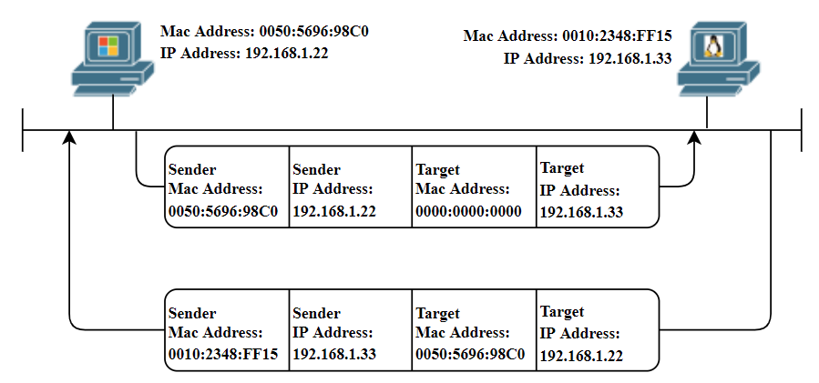
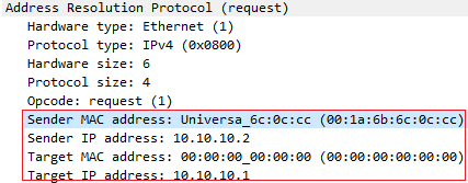
Устройство, которому необходимо узнать идентификатор канальной среды другого устройства, создает пакет ARP Request. Данный запрос содержит в себе IP-адрес устройства для которого необходимо узнать идентификатор канального среды (Target), а также данные канальной среды (в данном случае MAC-адрес) и IP-адрес устройства, которое данный запрос сформировало (Source).
Пакет ARP Request инкапсулируется в фрейм. В качестве MAC-адреса источника выступает сам источник, в качестве MAC-адреса назначения используется broadcast адрес (FFFF.FFFF.FFFF).
Вот как выглядит ARP Request если захватить его с помощью wireshark
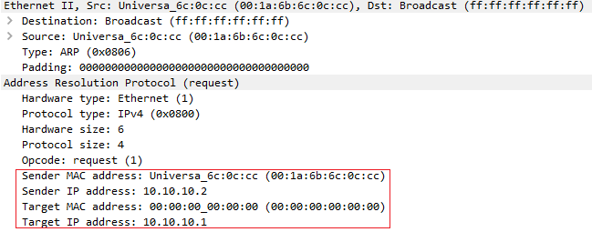
Подробно рассмотреть каждое поле запроса ARP можно скачав данный дамп
Broadcast адрес используется для того чтобы все узлы в канальной среде получили данный фрейм и обработали инкапсулированный внутри пакет. Все устройства, за исключением адресата назначения, поймут, что данный пакет не предназначается для них и попросту отбросят его. Устройство назначения обработает пакет и в ответ отправит ARP Reply адресату источника. Внутри ARP Reply будет содержаться как раз-таки MAC-адрес адресата назначения.
На следующем изображении можно увидеть как выглядит ARP Reply
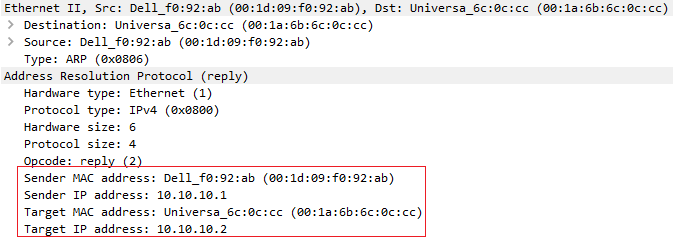
Также скачав дамп с трафиком можно более подробно увидеть каждое поле пакета
2. Структура полей протокола ARP
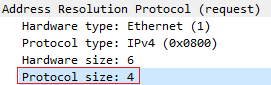
Протокол ARP имеет следующие поля:
Стоит напомнить, что формат протокола обычно показывается в разрезе 4 байт. Из-за этого часть информации из полей протокола может быть показана как часть следующих 4 байт (на примере Hardware и IP адресации).
Hardware Type — 16-битное поле, определяющее “тип канальной среды”. Наиболее часто используемые типы представлены в таблице ниже
| Номер | Тип среды |
|---|---|
1 |
Ethernet |
15 |
Frame Relay |
17 |
HDLC |
18 |
Fiber Channel |
20 |
Serial Link |
Но основную часть всё же занимает именно Ethernet.
Protocol Type — 16-битное поле, определяющее протокол сетевого уровня, который отправитель связывает с идентификатором канала передачи данных. Для протокола IP версии 4 значение данного поля равно 0x0800
Hardware Address Length — 8-битное поле, определяющее длину идентификатора канальной среды в байтах. MAC-адреса имеет длину 48 бит или 6 байт.
Protocol Address Length — 8-битное поле, определяющее длину адреса сетевого уровня в байтах. IP-адреса имеет длину 32 бита или 4 байта.
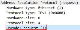
Operation — 16-битное поле, которое определяет какой тип пакета ARP используется:
- ARP Request —
1- ARP Reply —
2- Reverse ARP Request —
3- Reverse ARP Reply —
4- Inverse ARP Request —
8- Inverse ARP Reply —
9
Последние 20 байт приходятся на адресацию канальной среды и сетевого уровня источника и назначения запроса (MAC-адрес 6 байт * 2 + IP-адрес 4 байт * 2 = 20)
3. Практика
Посмотрим небольшую практику на примере следующей схемы:
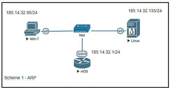
Для того чтобы отследить пакеты arp на устройствах cisco можно воспользоваться утилитой debug. Для этого необходимо в привилегированном режиме выполнить команду debug arp
Важно: команда
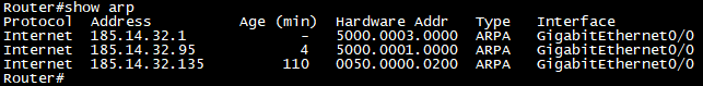
debugочень требовательна к ресурсам, следует аккуратно использовать её на производстве. При неаккуратном задании параметров можно потерять доступ к устройству из-за постоянного спама сообщений в консоль.Для просмотра таблицы ARP на устройствах cisco можно выполнить команду
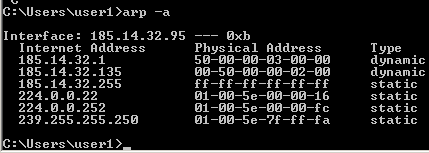
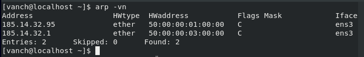
show arpв привилегированном режиме. Для операционной системы Windows можно выполнить командуarp -a, а для Linux команда выглядитarp -vn. Примеры выполнения команд приведены ниже:
Cisco ARP table
Windows ARP table
Linux ARP table
Стоит обратить внимание на колонку
Ageв выводе команды на маршрутизаторе. Данная колонка показывает через какое количество времени данная запись будет удалена из таблицы ARP. Это сделано для того чтобы предотвратить перегрузку таблицы ARP устаревшими записями.По умолчанию устройства cisco хранятся информацию у себя в таблице ARP в течение 4 часов, это можно проверить командой
show interface <имя_интерфейса> | include ARP
Поведение по умолчанию можно изменить, выполнив следующий набор команд (настройка актуальна для отдельного интерфейса)
Для очистки ARP кэша можно выполнить команду
В следующий раз я вкратце рассмотрю другие разновидности протокола ARP:
Proxy ARP,Gratuitous ARP,Reverse ARP.P.S. вся информация представленная здесь используется исключительно в образовательных целях. Все совпадения с реальными объектами, адресами, именами и т.д. случайна и не несёт цели получить от этого выгоду или причинить кому-либо вред.
Back to top ↑