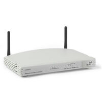
Компания 3COM, выпускающая сетевое оборудование, в 2010-м году была выкуплена более крупным производителем «железа» под названием Hewlett Packard. Тем не менее, на просторах нашей страны – и сейчас встречается изготовленный фирмой 3COM роутер под названием «Office Connect 11g router».
Более точно название модели звучит, как 3CRWER100-75. Это сетевое устройство – снабжено микросхемой Wi-Fi на 54 Мбит/с. Еще, существует версия 3CRWER200-75, с «удвоенной» относительно младшей модели скоростью Wi-Fi. Как выполнить настройку – рассмотрим подробнее.

Роутер модели 3CRWER100-75
Внешне 100-мегабитный сетевой роутер, выпускаемый под маркой 3COM, выглядит довольно внушительно. При установке, рекомендуется направлять его антенны перпендикулярно друг другу (буквой «V»). Так – получим устойчивую связь с любым мобильным устройством.
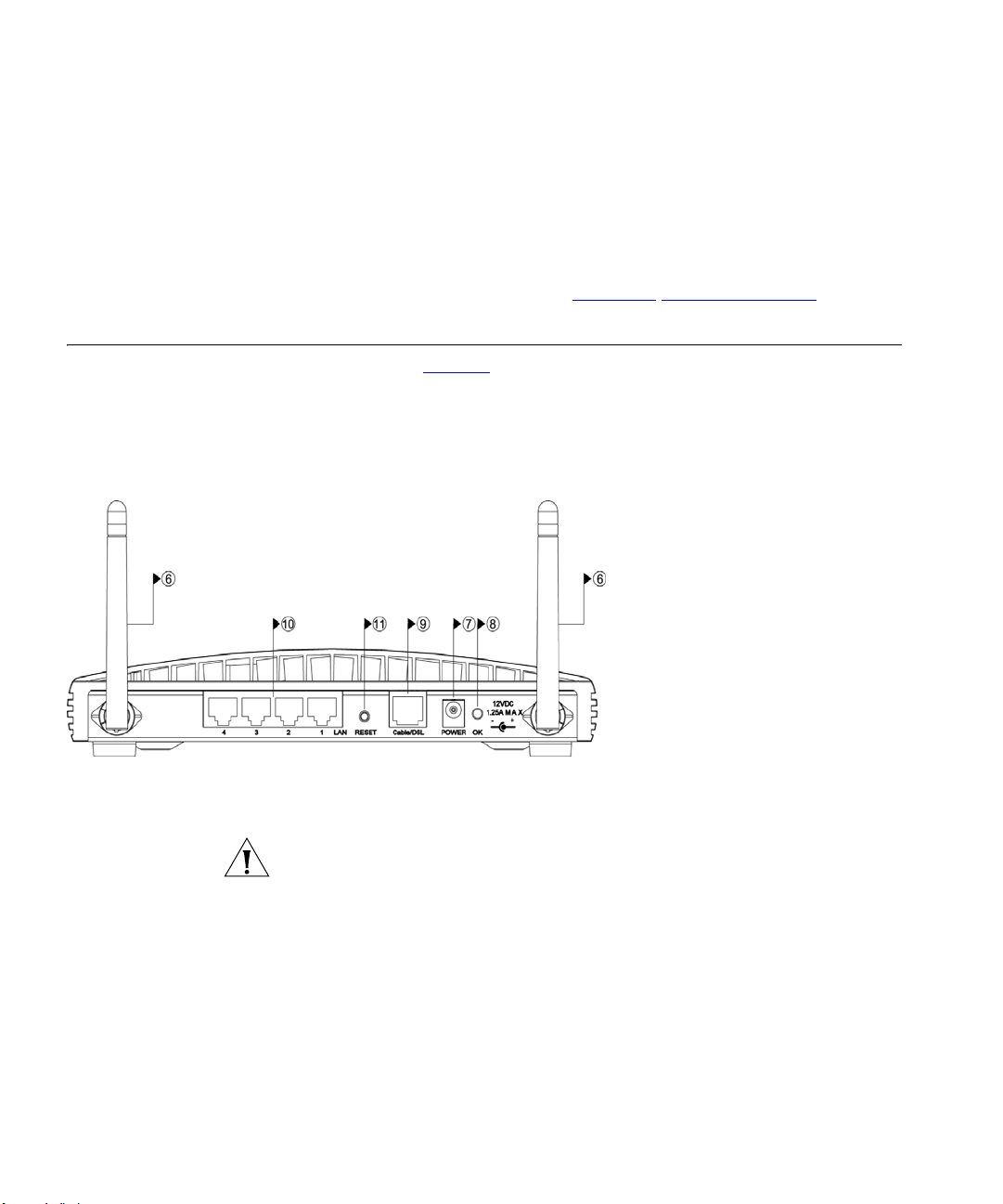
На задней стенке, здесь обнаруживается стандартный набор портов. Это 4 LAN-разъема, и один разъем WAN. Хотя, последний называется «Cable/DSL», но он – не перенесет подключения к телефонной линии:

Задняя панель роутера
К разъему Power – надо подключать блок питания, рассчитанный на 12 Вольт (мощностью 15 Ватт или больше). Рядом с разъемом мы видим индикатор питания (почему-то, он называется «OK»). Переходим к настройке базовых функций: Интернет-подключения и сети Wi-Fi.
Действия, выполняемые до настройки
Аппаратные подключения
Прежде всего, необходимо подключить роутер к компьютеру (с которого будет происходить настройка). Для этого, любой порт LAN – соединяют с разъемом сетевой карты ПК, используя патч корд. А саму сетевую карту – настраивают на «авто» IP и DNS:

Настройка проводной сетевой карты
Следующим шагом будет подключение шнура провайдера (либо, патч-корда, идущего от модема) к порту «Cable/DSL».
В последнюю очередь – включают питание устройства. И отправляют компьютер на перезагрузку.
Открываем web-интерфейс
Дождемся, когда компьютер полностью загрузится. После чего, откроем браузер, и перейдем к следующему адресу: 192.168.1.1. Должен появиться запрос авторизации:

Авторизация в роутерах 3COM
В качестве пароля – подходит слово admin. Нажав «Log In», дождемся появления вкладки выбора страны:

Вкладка выбора страны
Здесь надо установить значение «Russian Federation». А затем – нажать «Apply».
Важно знать: если указанный IPадрес длительное время «не отвечает», рекомендуем выполнить сброс настроек роутера. Который, здесь осуществляется не совсем стандартно.
Рассмотрим, как вернуть настройкам роутера их значения «по умолчанию». То есть, как выполнить аппаратный сброс.
Последовательность действий – такая:
- Отключить питание роутера и внешние сетевые устройства.
- Патч-кордом – соединить порт LAN с разъемом «Cable/DSL» (не важно, какой из 4-х портов LAN будет использоваться).
- Затем, включив питание, надо ждать 30 секунд (до «более медленного» мигания индикатора «Alert», расположенного на передней панели).
- Питание роутера – надо выключить, устройство будет готово к настройке.
Кнопка reset, как можно понять, в данном случае не используется.
Настройка базовых функций
Интернет-подключение (DHCP)
Выполнив вход в интерфейс, пользователь видит вкладку «Welcome»:

Стартовая вкладка
Для настройки соединения, не важно, по какому именно протоколу – понадобится другая вкладка, «Internet Settings». Здесь мы выбираем используемый протокол (Dynamic IP), и устанавливаем MAC-адрес (он будет присвоен порту роутера):

Настройка соединения (протокол DHCP)
Значение MAC-адреса лучше сообщить роутеру в явном виде. Для чего, выбираем селектор «Enter a new MAC…» и заполняем цифровые поля.
Как узнать адрес MAC сетевой карты? Проще всего, выполнив правый щелчок на значке соединения, выбрать «Состояние» -> «Поддержка» -> «Подробности» (смотрите первую сверху строку).
В завершении нажимают «Save». А затем, для применения сохраненных настроек – «Apply/Restart».
Интернет-подключение (L2TP)
Рассмотрим пример настройки L2TP-подключения с динамическим IP-адресом. Прежде всего, надо выполнить действия, перечисленные в предыдущей главе. Если требуется подмена MAC-адреса, установите требуемое значение.
Затем, роутер настраивают повторно: вместо «Dynamic IP» выбирают «L2TP», устанавливают значения параметров. Например, как на рисунке:

Настройка L2TP-соединения
К параметрам L2TP-протокола относятся:
- Адрес либо доменное имя (Domain Name) сервера L2TP
- Имя (логин) абонента
- Пароль
При желании, можно указать адреса DNS (что ускорит работу роутера). Галочка «Get IP by DHCP» должна быть выставлена (IP-адрес у нас – динамический).
В последнюю очередь, надо нажать «Save», и затем – «Apply». Успешной настройки!
Настраиваем Wi-Fi-сеть
В принципе, перейдя к вкладке «Wireless Settings», становится ясно – доступен необходимый минимум параметров:

Вкладка параметров Wi-Fi
Режим (Mode) – оставим в значении «Mixed». Номер радиоканала (Channel) – можно установить в явном виде. Возможен и автоматический выбор (значение «Clear Channel Select»).
Главное здесь – задать имя сети. Оно находится в текстовом поле «Service Area Name». Выполнив установку значений, нажмите «Save» (и «Apply/Restart»).
Переходим к закладке «Encryption». Здесь доступны настройки защиты (то есть, шифрования Wi-Fi-сети).

Вкладка шифрования Wi-Fi
Мы использовали значения: режим – WPA, алгоритм – TKIP (можно AES). Главное – заполнить строку ключа (хотя бы 8-ю символами).
В последнюю очередь, нажимают «Save» и «Apply/Restart». Удачного роутинга!
Есть фильм по настройке 108-мегабитной модели (которая – работает с «удвоенной» скоростью Wi-Fi 802.11 g):
Предыдущая
TendaДва самых простых способа подключиться к Wi-Fi по WPS
Следующая
D-LinkБюджетный роутер, совместимый с оптоволокном: DIR-615/FB/O1
Помогла статья? Оцените её
![]() Загрузка…
Загрузка…
This device is NOT RECOMMENDED for future use with OpenWrt due to low flash/ram.
DO NOT BUY DEVICES WITH 4MB FLASH / 32MB RAM if you intend to flash an up-to-date and secure OpenWrt version onto it! See 4/32 warning for details.
1) This device does not have sufficient resources (flash and/or RAM) to provide secure and reliable operation.
This means that even setting a password or changing simple network settings might not be possible any more, rendering the device effectively useless. See OpenWrt on 4/32 devices what you can do now.
2) OpenWrt support for this device has ended in 2022.
19.07.10 was the last official build for 4/32 devices.
ASAP I’ ll try to improve this article.
Now here is step by step installation of OpenWrt for experienced user. NOT for beginners.
| Version/Model | Launch Date | S/N | OpenWrt Version Supported | Model Specific Notes |
|---|---|---|---|---|
| — | — | — | trunk r28395 | — |
| CPU | Ram | Flash | Network | USB | Serial | JTag |
|---|---|---|---|---|---|---|
| Atheros 2315A@180MHz | 16MiB | 4MiB | 1 + 4 | No | Yes | ? |
OpenWrt
Other SW
You are doing everything at your own risk! Nobody is responsible for what you are doing.
Don’t do it if you don’t know what you are doing!
Incomplete BETA version of text!
Operating system
TFTP
Putty
:redboot
putty.exe -telnet -P 9000 10.10.12.72
goto redboot
RedBoot
fconfig -l
fis init
y
load -r -b %{FREEMEMLO} openwrt-atheros-vmlinux.lzma
fis create -r 0x80041000 -e 0x80041000 vmlinux.bin.l7
load -r -b %{FREEMEMLO} openwrt-atheros-root.squashfs
fis free
fis create -l 0x2E0000 rootfs
fis list
reset

1) Telnet to 10.10.12.72 (alt. 192.168.1.1) on port 9000 to get Redboot prompt
RedBoot> fis load -l vmlinux.bin.l7
RedBoot> go 0x80041000
2) Now you can see Open Wrt promt.
root@OpenWrt:/#
3) Thus you have to correct booting procedure. Reboot device
Telnet to 10.10.12.72
RedBoot> fconfig -l
RedBoot> fconfig boot_script_data
Enter following:
fis load -l vmlinux.bin.l7
go 0x80041000
Save and reboot.

| Port | Switch port | Router’s port label | Interface |
|---|---|---|---|
| LAN | Port 0 | LAN 4 | eth0.1 |
| LAN | Port 1 | LAN 3 | eth0.1 |
| LAN | Port 2 | LAN 2 | eth0.1 |
| LAN | Port 3 | LAN 1 | eth0.1 |
| WAN | Port 4 | Cable/DSL | eth0.2 |
| CPU | Port 5 | N.A. | eth0 |
To find out the dev switch name:
root@OpenWrt:~# swconfig list
Found: switch0 - eth0
To check the switch ports list:
root@OpenWrt:~# swconfig dev switch0 show
Global attributes:
        enable_vlan: 1
        name: IP175C
        phy: 0
        reg: 0
        val: 12544
Port 0:
        status: up, 10 Mbps, full duplex, auto-negotiate
        link: 10
        tagged: 0
        pvid: 1
Port 1:
        status: down, auto-negotiate (in progress)
        link: 0
        tagged: 0
        pvid: 1
Port 2:
        status: down, auto-negotiate (in progress)
        link: 0
        tagged: 0
        pvid: 1
Port 3:
        status: down, auto-negotiate (in progress)
        link: 0
        tagged: 0
        pvid: 1
Port 4:
        status: up, 100 Mbps, full duplex, auto-negotiate
        link: 100
        tagged: 0
        pvid: 2
Port 5:
        status: up, 100 Mbps, cpu port
        link: 100
        tagged: 1
        pvid: 0
VLAN 1:
        vid: 1
        ports: 0 1 2 3 5t
VLAN 2:
        vid: 2
        ports: 4 5t
Your here: Home / Network / Hardware Specific / 3Com / 3CRWER100-75
| 3Com OfficeConnect 3CRWER100-75 | |
|---|---|
 Wireless Cable/DSL Router |
|
|
Homepage |
OfficeConnect 3CRWER100-75 |
|
Wikipedia |
? |
|
WikiDevi |
? |
|
dd-wrt |
Not Supported |
|
OpenWRT |
Not Supported |
|
Tomato |
Not Supported |
|
TomatoUSB |
Not Supported |
|
Gargoyle |
Not Supported |
NOTE: During configuration or flashing a device, the only that should be hooked to the device is the computer and power.
Specs[]
This section is in need of cleanup!
Platform
Serial Num. = ?
FCC ID = O9C-WL537
CPU Type = Atheros AR2315
MIPS Rev = ?
CPU Speed = 180MHz
Bus = ?
Flash Type = ?
Flash Chip = ?
Flash Size = 4MB
Max Firmware Size = ?
RAM Size = 16MB
RAM Chip = ?
nvram Size = ?
Switch = IC+ 1P175C L D541513 FPK6990 L
Port-based vlan = ?
802.1q vlan = ?
Ethernet Port Count = 1-10/100-WAN 4-10/100-LAN
Wired Standard = IEEE 802.3/3u
boot_wait = ?
bootloader = ?
Flash Card Socket/Type = No
SD/MMC Mod Support = No
MiniPCI slots = No
PoE = ?
Power = 12V/1A
Color of LEDs = ?
Size = 3.5 x 22 x 13.5bm (1.5 x 8.7 x 5.3in)
USB = No
Serial Port = ?
JTAG Port = ?
Supported by TJTAG/Version = ?
Supported by dd-wrt as of = WIP - 3CRWER100 v.24 pre sp2 - build ?
dd-wrt K2.4 Support = ?
dd-wrt K2.6 Support = ?
Special Features = ?
Radio (ath0)
Wireless Radio = Atheros
WLAN DSP processor = ?
Antenna Connector Type = ?
Wireless Standard = IEEE 802.11b/g
WiFi Operating Frequency = 2.4-2.4835 GHz
 802.11g = 6, 9, 12, 18, 24, 36, 48, 54Mbps
 802.11b = 1, 2, 5.5, 11Mbps
Radio cor_rev = ?
Radio Capabilities = ?
Links of Interest[]
- dd-wrt:3Com 3CRWER100-75 Support
Flashing[]
This section is in need of cleanup!
Upgrading[]
This section is in need of cleanup!
Reverting[]
This section is in need of cleanup!
JTAG/Serial Info[]
JTAG[]
Serial[]
vlan Info[]
This section is in need of cleanup!
Pictures[]
FCC Pictures[]
Notes[]
Quit dificult to enable redboot on ethernet connection!
Hardware Modification[]
Have you recently bought a 3CRWER100-75 router model from the popular router brand 3Com? You must be facing issues such as how to login to the admin console of your router, how you can configure the network, etc, But don’t worry, now you found the perfect place!
Here in this comprehensive guide, we will cover everything you need to know about the 3CRWER100-75 router model, from default username and password to IP address and network configuration. Below you will also get a piece of information about sharing the default IP address of the router.
If we talk about the most popular and best router, then most people will say the 3Com router without even a blink of an eye. Their routers are very easy to use and offer you lots of facilities.
If we talk about particular model 3CRWER100-75, 3Com 3CRWER100-75 router, It allows you to change the default settings like username, password, and network setting in one click, you don’t need to contact your ISP. Additionally, you can reboot your device remotely.
How to Login to 3CRWER100-75
Usually, 3Com’s 3CRWER100-75 router uses 192.168.1.1 as its default IP address, You can easily login with it, But sometimes if you got your router from internet service providers then it is quite possible that your default IP address can differ.
First of all, You should just check that if your default IP address is 192.168.1.1 or not, For that you have to follow the below instruction.

So, now you have to log in to the admin console using your default IP address if you are unable to login with that IP address then we would go forward with other options.
To login, All you need to do is just go to the web browser enter your default IP address (which is most probably 192.168.1.1 in this router case), and just hit enter, Just make sure that your device is connected with that same wifi network while doing this process.
You can also just click here, It will directly take you to your router’s admin console.
Rather than the login page, if something else comes, it clarifies that your ISP has changed to host IP for a router. You need to contact them for the login IP. (As of now, we are assuming that your IP is correct)
Once you visit the login page, You will be asked to enter your username and password to login into the admin console. If this whole process you are performing for the very first time then you have to enter the default username and password of your router, Which if you don’t have then don’t worry, All you need to do is just click here and it will directly take you to our giant database, Where you can easily get your router’s default username and password.
Once you enter all login credentials correctly, you will be directly on the admin console of your router where you can easily manage your router’s setting, Such as changing your username and password and many more.
How To Find The IP Address Of 3CRWER100-75 Router?
What if the default router host IP 192.168.1.1 is not working for you, You can easily contact your internet service provider they will surely fill your all gaps but fr some reason if you are unable to contact them then don’t worry! We have a solution through that you can easily get your default IP address.
Basically, It is not rocket science to find your router’s default IP address all you have to do just run a command. Now, what exactly is that command, Let’s figure it out.
For macOS users it is just a few seconds process, Just open the terminal and enter the mentioned command and this will detect your “inet” IP address of your device.
ifconfig | grep "inet" | grep -Fv 127.0.0.1 | awk '{print $2}'
Now, Let’s talk about window users, It is quite different than macOS users,
If you are a windows user, you need to open a command prompt. Go to Start Menu >> Search for CMD, and double click on it to open. You can also open CMD using the Run option of windows. For that, press «windows key +R» and enter «cmd.» Enter the below command and hit enter,
ipconfig/all
This way you’ll find the default “Gateway IP Address” of your device.
Default Username & Password of 3CRWER100-75
There are very high chances that the default username and password are mostly written in the router user manual of the router, It contains the default credentials along with the IP address of your router.
You can check our database of router’s username and password where you have shared the credentials of almost all the routes available across the globe, contain details of 520+ routers brand and 5500+ models. All our data is in a well-arranged manner so that you can find the credentials for your 3CRWER100-75 router model. To visit our database just click here.
How to boost 3Com 3CRWER100-75 WiFi and overcome connectivity issues:
Place the router in a perfect place:
It is really important for better connectivity to place your 3Com router at the perfect pace, Perfect place refers here to make sure that your 3Com router is not facing any wall or curtains.
Find a Good Wireless Channel Instead of Auto on your 3Com 3CRWER100-75 router
It is way too obvious that you are way too smarter than your 3Com router so considering that fact I would advise you not to go for auto channels but go for a seamless wireless channel. This would make sure that your signal would not interfere with that of your neighbors.
If you’re running a Windows-based PC, you can see what channels neighboring Wi-Fi networks are using
Press Start > type “cmd”. Open Command prompt
In command prompt type netsh wlan show all
Check the frequency of 3Com W3000
It is your responsibility if your 3Com router has dual bands, There is commonly used band is 2.4GHz Well, No doubt switching to 5G would give you a better result, And It totally depends on your device and if you are counting on an old device you should stick back to the conventional.
Reboot 3Com 3CRWER100-75 on a schedule
Well, Whenever your 3Com router gives you quite a problem at the end you just stay with nothing but to reboot your router so, Yeah, Rebooting your 3Com router will surely fix internet connection issues, Try unplugging your 3Com modem on a quarterly basis to stay proactive.
How to Reset My 3CRWER100-75?
Resetting the router is a really easy and important process to make. First of all, just take a look at your router and turn it back, You will notice a hole in your router and a button along with that hole. You need to have a sim ejector pin to press this button. It is not accessible with a normal finger.
All you have to is just press that button for a while means 2 or 3 seconds and your router is all set with resetting to its initial settings and passwords.
Once this resetting process is all done, You can use the default username and password to get access to the admin console of your router, where you can make your own username and password as well and can manage other router’s settings too very easily.
Wrapping Up!
We hope that you liked our article and this helped you to find your default IP address or your default username and password. We have shared that how can you reset your router as well.
If you have any queries and suggestions regarding this post feel free to comment that down. Do share this article with your friends and family if it is helpful for you in any manner.
Stay connected.

http://www.3com.com/
OfficeConnect
®
Wireless 54Mbps/108Mbps 11g Cable/DSL
Router User Guide
3CRWER100-75(Model:WL-537)
3CRWER200-75(Model:WL-537S)

3Com Corporation
350 Campus Drive
Marlborough, MA
USA 01752-3064
Copyright © 2006, 3Com Corporation. All rights reserved. No part of this documentation may be reproduced
in any form or by any means or used to make any derivative work (such as translation, transformation, or
adaptation) without written permission from 3Com Corporation.
3Com Corporation reserves the right to revise this documentation and to make changes in content from time
to time without obligation on the part of 3Com Corporation to provide notification of such revision or change.
3Com Corporation provides this documentation without warranty, term, or condition of any kind, either
implied or expressed, including, but not limited to, the implied warranties, terms or conditions of
merchantability, satis34factory quality, and fitness for a particular purpose. 3Com may make improvements or
changes in the product(s) and/or the program(s) described in this documentation at any time.
If there is any software on removable media described in this documentation, it is furnished under a license
agreement included with the product as a separate document, in the hard copy documentation, or on the
removable media in a directory file named LICENSE.TXT or !LICENSE.TXT. If you are unable to locate a copy,
please contact 3Com and a copy will be provided to you.
UNITED STATES GOVERNMENT LEGEND
If you are a United States government agency, then this documentation and the software described herein are
provided to you subject to the following:
All technical data and computer software are commercial in nature and developed solely at private expense.
Software is delivered as “Commercial Computer Software” as defined in DFARS 252.227-7014 (June 1995) or
as a “commercial item” as defined in FAR 2.101(a) and as such is provided with only such rights as are
provided in 3Com’s standard commercial license for the Software. Technical data is provided with limited rights
only as provided in DFAR 252.227-7015 (Nov 1995) or FAR 52.227-14 (June 1987), whichever is applicable.
You agree not to remove or deface any portion of any legend provided on any licensed program or
documentation contained in, or delivered to you in conjunction with, this User Guide.
Unless otherwise indicated, 3Com registered trademarks are registered in the United States and may or may not
be registered in other countries.
3Com, OfficeConnect and the 3Com logo are registered trademarks of 3Com Corporation.
Intel and Pentium are registered trademarks of Intel Corporation. Microsoft, MS-DOS, Windows, and Windows
NT are registered trademarks of Microsoft Corporation. Novell and NetWare are registered trademarks of
Novell, Inc. UNIX is a registered trademark in the United States and other countries, licensed exclusively
through X/Open Company, Ltd.
Netscape Navigator is a registered trademark of Netscape Communications.
JavaScript is a trademark of Sun Microsystems
Wi-Fi and the Wi-Fi logo are registered trademarks of the WI-Fi Alliance.
IEEE and 802 are trademarks of the Institute of Electrical and Electronics Engineers, Inc.
All other company and product names may be trademarks of the respective companies with which they are
associated.
ENVIRONMENTAL STATEMENT
It is the policy of 3Com Corporation to be environmentally-friendly in all operations. To uphold our policy, we
are committed to:
Establishing environmental performance standards that comply with national legislation and regulations.
Conserving energy, materials and natural resources in all operations.
Reducing the waste generated by all operations. Ensuring that all waste conforms to recognized environmental
standards. Maximizing the recyclable and reusable content of all products.
Ensuring that all products can be recycled, reused and disposed of safely.
Ensuring that all products are labelled according to recognized environmental standards.
Improving our environmental record on a continual basis.
End of Life Statement
3Com processes allow for the recovery, reclamation and safe disposal of all end-of-life electronic components.
Regulated Materials Statement
3Com products do not contain any hazardous or ozone-depleting material.
Environmental Statement about the Documentation
The documentation for this product is printed on paper that comes from sustainable, managed forests; it is
fully biodegradable and recyclable, and is completely chlorine-free. The varnish is environmentally-friendly, and
the inks are vegetable-based with a low heavy-metal content.

ABOUT THIS GUIDE
This guide describes how to install and configure the OfficeConnect
Wireless 54Mbps/108Mbps 11g cable/DSL Router(3CRWER100-75 and
3CRWER200-75).
This guide is intended for use by those responsible for installing and
setting up network equipment; consequently, it assumes a basic working
knowledge of LANs (Local Area Networks) and Internet Router systems.
If a release note is shipped with the OfficeConnect Wireless
54Mbps/108Mbps 11g cable/DSL Router
!
and contains information that
differs from the information in this guide, follow the information in the
release note.
Most user guides and release notes are available in Adobe Acrobat
Reader Portable Document Format (PDF) on the 3Com World Wide Web
site:
http://www.3com.com
Naming Convention Throughout this guide, the OfficeConnect Wireless 54Mbps/108Mbps!
11g Cable/DSL Router is referred to as the “Router”.
Category 3 and Category 5 Twisted Pair Cables are referred to as Twisted
Pair Cables throughout this guide.
8 ABOUT THIS GUIDE
Conventions Ta bl e 1 and Ta bl e 2 list conventions that are used throughout this guide.
Feedback about this
User Guide
Your suggestions are very important to us. They will help make our
documentation more useful to you. Please e-mail comments about this
document to 3Com at:
pddtechpubs_comments@3com.com
Please include the following information when commenting:
■ Document title
■ Document part number (on the title page)
■ Page number (if appropriate)
Table 1 Notice Icons
Icon Notice Type Description
Information note Information that describes important features or
instructions.
Caution Information that alerts you to potential loss of data or
potential damage to an application, system, or device.
Warning Information that alerts you to potential personal
injury.
Table 2 Text Conventions
Convention Description
The words “enter”
and “type”
When you see the word “enter” in this guide, you must type
something, and then press Return or Enter. Do not press
Return or Enter when an instruction simply says “type.”
Keyboard key names If you must press two or more keys simultaneously, the key
names are linked with a plus sign (+). Example:
Press Ctrl+Alt+Del
Words in italics Italics are used to:
■ Emphasize a point.
■ Denote a new term at the place where it is defined in the
text.
■ Identify menu names, menu commands, and software
button names. Examples:
From the Help menu, select Contents.
Click OK.

Conventions 9
Example:
■ OfficeConnect Wireless 54Mbps/108Mbps 11g cable/DSL Router User
Guide
■ Part Number DUA0554-TAAA02
■ Page 24
Do not use this e-mail address for technical support questions. For
information about contacting Technical Support, please refer to the
Support and Safety Information sheet.
Related
Documentation
In addition to this guide, each Router document set includes one
Installation Guide. This guide contains the instructions you need to install
and configure your Router.

10 ABOUT THIS GUIDE

1
INTRODUCING THE ROUTER
Welcome to the world of networking with 3Com
®
. In the modern
business environment, communication and sharing information is crucial.
Computer networks have proved to be one of the fastest modes of
communication but, until recently, only large businesses could afford the
networking advantage. The OfficeConnect
®
product range from 3Com
has changed all this, bringing networks to the small office.
The products that compose the OfficeConnect range give you, the small
office user, the same power, flexibility, and protection that has been
available only to large corporations. Now, you can network the
computers in your office, connect them all to a single Internet outlet, and
harness the combined power of all of your computers.
OfficeConnect
Wireless
54Mbps/108Mbps
11g cable/DSL
Router
The OfficeConnect Wireless 54Mbps/108Mbps 11g cable/DSL Router is
designed to provide a cost-effective means of sharing a single broadband
Internet connection amongst several wired and wireless computers. The
Router also provides protection in the form of an electronic “firewall”,
preventing anyone outside of your network from seeing your files or
damaging your computers. The Router can also prevent your users from
accessing Web sites which you find unsuitable.
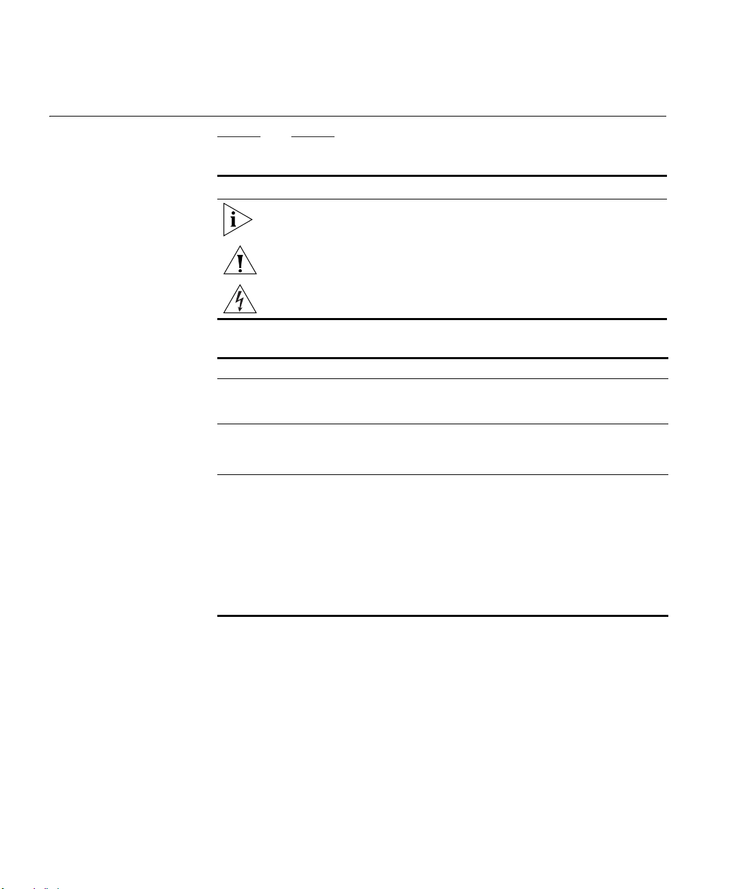
Figure 1
shows an example network without a Router. In this network,
only one computer is connected to the Internet. This computer must
always be powered on for the other computers on the network to access
the Internet.
12 CHAPTER 1: INTRODUCING THE ROUTER
Figure 1 Example Network Without a Router
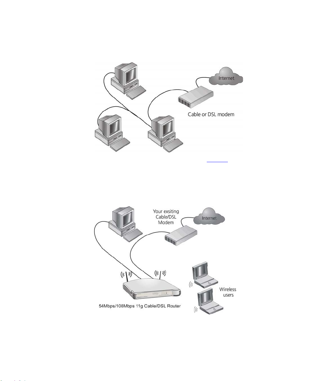
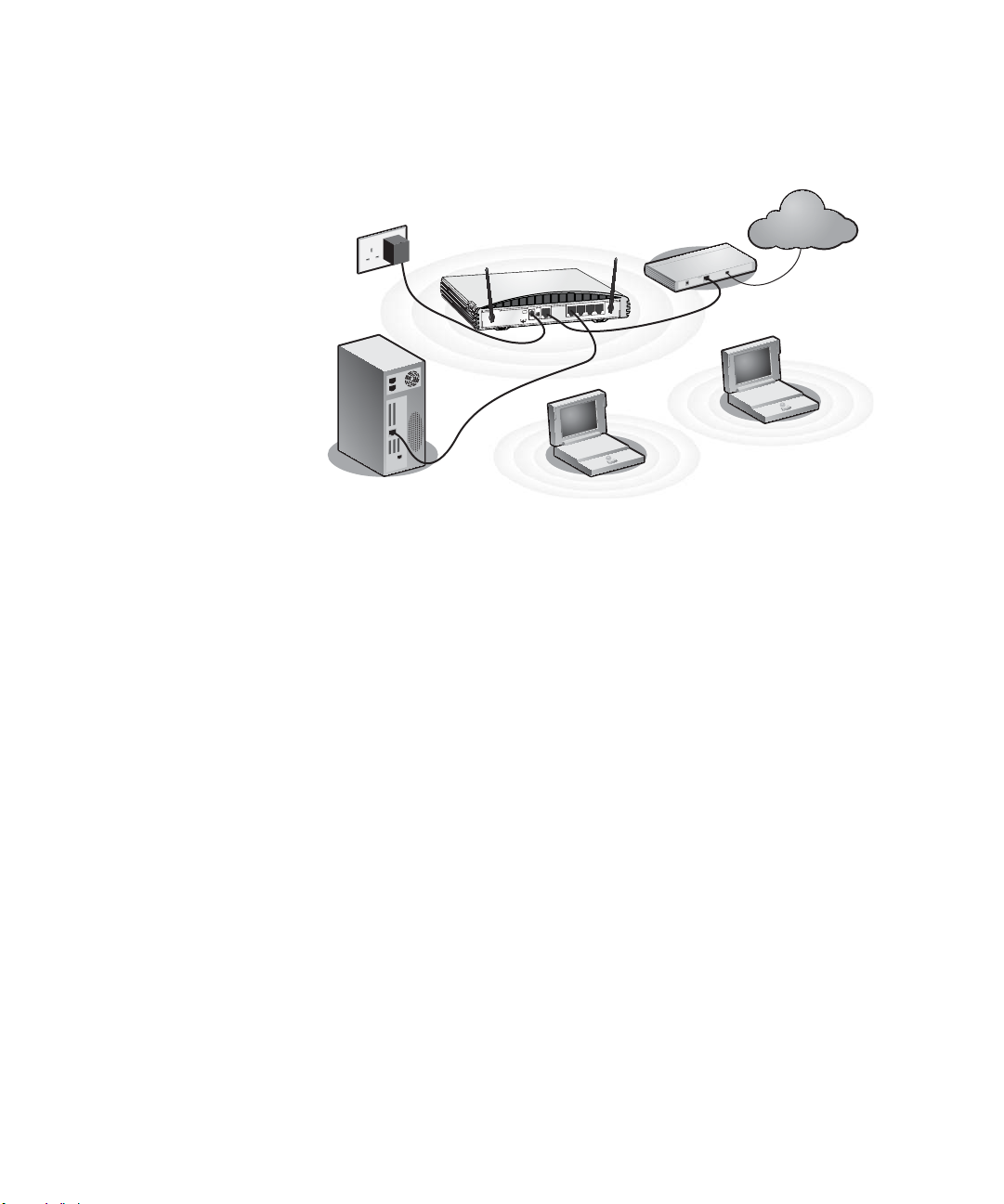
When you use the Router in your network (Figure 2), it becomes your
connection to the Internet. Connections can be made directly to the
Router, or to an OfficeConnect Switch or Hub, expanding the number of
computers you can have in your network.
Figure 2 Example Network Using a Wireless 11g Cable/DSL Router

Router Advantages 13
Router Advantages The advantages of the Router include:
■ Shared Internet connection for both wired and wireless computers
■ High speed 802.11g wireless networking
■ No need for a dedicated, “always on” computer serving as your
Internet connection
■ Cross-platform operation for compatibility with Windows, Unix and
Macintosh computers
■ Easy-to-use, Web-based setup and configuration
■ Provides centralization of all network address settings (DHCP)
■ Acts as a Virtual server to enable remote access to Web, FTP, and other
services on your network
■ Security — Firewall protection against Internet hacker attacks and
encryption to protect wireless network traffic
■ Filtered access of inappropriate Web sites using the built-in URL filter
Package Contents The Router kit includes the following items:
■ One OfficeConnect Wireless 54Mbps/108Mbps 11g cable/DSL Router
■ One power adapter for use with the Router
■ Four rubber feet
■ One Ethernet cable
■ One CD-ROM containing the Quick Installation Guide!and this User
Guide
■ Installation Guide
■ One Support and Safety Information Sheet
■ One Warranty Flyer
If any of these items are missing or damaged, please contact your retailer.
14 CHAPTER 1: INTRODUCING THE ROUTER
Minimum System
and Component
Requirements
Your Router requires that the computer(s) and components in your
network be configured with at least the following:
■ A computer with an operating system that supports TCP/IP
networking protocols (for example Windows 95/98/NT/Me/2000/XP,
Unix, Mac OS 8.5 or higher).
■ An Ethernet 10Mbps or 10/100 Mbps NIC for each computer to be
connected to the four-port switch on your Router.
■ An 802.11b or 802.11g wireless NIC.
■ A cable modem or DSL modem with an Ethernet port (RJ-45
connector).
■ An active Internet access account.
■ A Web browser that supports JavaScript, such as Netscape 4.7 or
higher, Internet Explorer 5.0 or higher, or Mozilla 1.2.1 or higher.
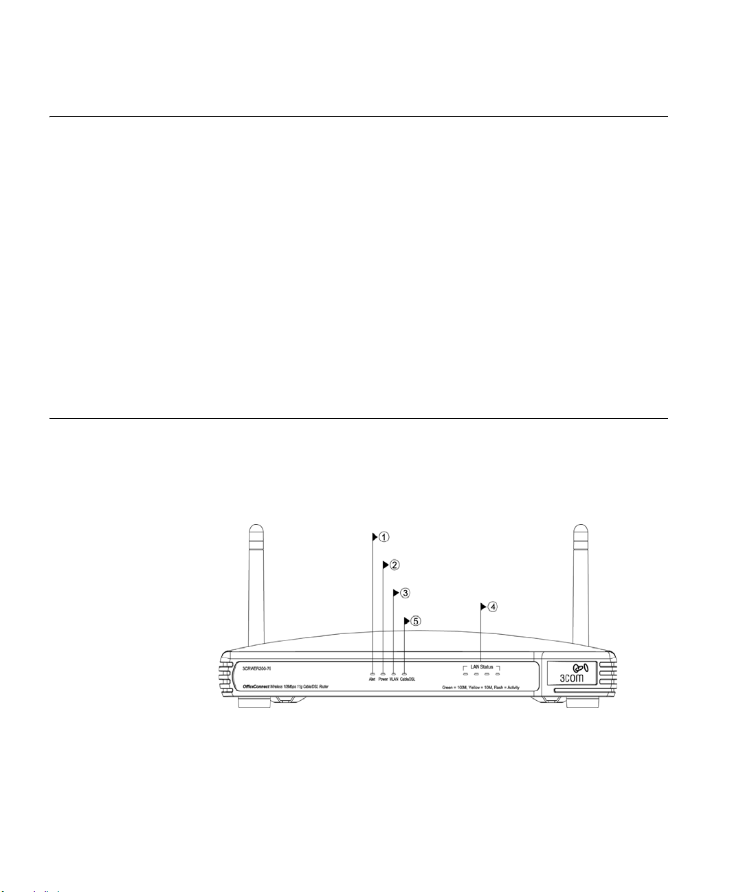
Front Panel The front panel of the Router contains a series of indicator lights (LEDs)
that help describe the status of various networking and connection
operations.
Figure 3 Router — Front Panel
1 Alert LED
Orange
Indicates a number of different conditions, as described below.
Off — The Router is operating normally.
Flashing quickly — Indicates one of the following conditions:

Front Panel 15
■ The Router has just been started up and is running a self-test routine,
or
■ The administrator has invoked the Reset to Factory Defaults
command, or
■ The system software is in the process of being upgraded
In each of these cases, wait until the Router has completed the current
operation and the alert LED is Off.
Flashing slowly — The Router has completed the Reset to Factory Defaults
process, and is waiting for you to reset the unit. To do this, remove
power, wait 10 seconds and then re-apply power. The Router will then
enter the start-up sequence and resume normal operation.
On for 2 seconds, and then off — The Router has detected and prevented
a hacker from attacking your network from the Internet.
Continuously on — A fault has been detected with your Router during the
start-up process. Refer to Chapter 6
“Troubleshooting”.
2Power LED
Green
Indicates that the Router is powered on.
3 Wireless LAN (WLAN) Status LED
Yellow
If the LED is on it indicates that wireless networking is enabled. If the LED
is flashing, data is being transmitted or received. If the LED is off, the
Wireless LAN has been disabled in the Router, or there is a problem. Refer
to Chapter 6
“Troubleshooting”.
4 Four LAN Status LEDs
Green (100 Mbps link) / yellow (10 Mbps link)
If the LED is on, the link between the port and the next piece of network
equipment is OK. If the LED is flashing, the link is OK and data is being
transmitted or received. If the LED is off, nothing is connected, the
connected device is switched off, or there is a problem with the
connection (refer to Chapter 6
“Troubleshooting”). The port will
automatically adjust to the correct speed and duplex.
16 CHAPTER 1: INTRODUCING THE ROUTER
5 Cable/DSL Status LED
Green (100 Mbps link) / yellow (10 Mbps link)
If the LED is on, the link between the Router and the cable or DSL modem
is OK. If the LED is flashing, the link is OK and data is being transmitted or
received. If the LED is off, nothing is connected, the modem is switched
off or there is a problem (refer to Chapter 6
“Troubleshooting”).
Rear Panel The rear panel (Figure 4) of the Router contains four LAN ports, one
Ethernet Cable/DSL port, a power adapter OK LED, and a power adapter
socket.
Figure 4 Router — Rear Panel
6 Wireless Antennae
The antennae on the product should be placed in a ‘V’ position when
initially installed.
CAUTION: Do not force the antennae beyond their mechanical stops.
Rotating the antennae further may cause damage.
7 Power Adapter Socket
Only use the power adapter supplied with this Router. Do not use any
other adapter.
8 Power Adapter OK LED
Green
Indicates that the power adapter is supplying power to the Router. If the
LED is off, there may be a problem with the power adapter or adapter
cable.

Rear Panel 17
9 Ethernet Cable/DSL port
Use the supplied patch cable to connect the Router to the Ethernet port
on your cable or DSL modem. The port will automatically adjust to the
correct speed and duplex, and will set itself to MDI or MDIX depending
on the device to which they are connected and the type of cable used.
10 Four 10/100 LAN ports
Using suitable RJ-45 cable, you can connect your Router to a computer,
or to any other piece of equipment that has an Ethernet connection (for
example, a hub or a switch). The LAN ports will automatically set
themselves to MDI or MDIX depending on the device to which they are
connected and the type of cable used.

18 CHAPTER 1: INTRODUCING THE ROUTER

2
HARDWARE INSTALLATION
Introduction This chapter will guide you through a basic installation of the Router,
including:
■ Connecting the Router to the Internet.
■ Connecting the Router to your network.
■ Setting up your computers for networking with the Router.
Safety Information
WARNING: Please read the “
Safety Information” section in Appendix D
before you start.
VORSICHT: Bitte lesen Sie den Abschnitt “
Wichtige Sicherheitshinweise”
sorgfältig durch, bevor Sie das Gerät einschalten.
AVERTISSEMENT: Veuillez lire attentivement la section “
Consignes
importantes de sécurité” avant de mettre en route.
Positioning the
Router
You should place the Router in a location that:
■ is conveniently located for connection to the cable or DSL modem that
will be used to connect to the Internet.
■ is centrally located to the wireless computers that will connect to the
Router. A suitable location might be on top of a high shelf or similar
furniture to optimize wireless connections to computers in both
horizontal and vertical directions, allowing wider coverage.
■ allows convenient connection to the computers that will be connected
to the four LAN ports on the rear panel, if desired.
■ allows easy viewing of the front panel LED indicator lights, and access
to the rear panel connectors, if necessary.

20 CHAPTER 2: HARDWARE INSTALLATION
When positioning your Router, ensure:
■ It is out of direct sunlight and away from sources of heat.
■ Cabling is away from power lines, fluorescent lighting fixtures, and
sources of electrical noise such as radios, transmitters and broadband
amplifiers.
■ Water or moisture cannot enter the case of the unit.
■ Air flow around the unit and through the vents in the side of the case
is not restricted. 3Com recommends you provide a minimum of
25 mm (1 in.) clearance.
Using the Rubber
Feet
Use the four self-adhesive rubber feet to prevent your Router from
moving around on your desk or when stacking with other flat top
OfficeConnect units. Only stick the feet to the marked areas at each
corner of the underside of your Router.
Stacking the Router If you are stacking your Router with other OfficeConnect units, install the
Router at the top of the stack. Refer to the documentation supplied with
your other OfficeConnect unit for details on using the stacking clip.
A stacking clip is not supplied with the Router. Use the stacking clip
supplied with another stackable OfficeConnect unit.
Wall Mounting There are two slots on the underside of the Router that can be used for
wall mounting.
When wall mounting the unit, ensure that it is within reach of the power
outlet.
You will need two suitable screws to wall mount the unit. To do this:
1 Ensure that the wall you use is smooth, flat, dry and sturdy and make two
screw holes which are 150 mm (5.9 in.) apart.
2 Fix the screws into the wall, leaving their heads 3 mm (0.12 in.) clear of
the wall surface.
3 Remove any connections to the unit and locate it over the screw heads.
When in line, gently push the unit on to the wall and move it downwards
to secure.
Before you Install your Router 21
When making connections, be careful not to push the unit up and off the
wall.
CAUTION: Only wall mount single units, do not wall mount stacked
units.
Before you Install
your Router
Before you install and configure your Router, you need the following
additional information. If you do not have this information, contact your
Internet Service Provider (ISP). Space is provided below for you to record
this information.
If you have a DSL connection and your ISP allocates IP information
dynamically over PPPoE, you need a User Name and Password:
You only need a PPPoE Service Name if your ISP requires one. Do not
enter anything if your ISP does not require this information.
If you have a DSL connection and your ISP allocates IP information
dynamically over PPTP, you need a User Name, Password and PPTP Server
Address:
PPPoE User Name : ______________________
PPPoE Password : ______________________
PPPoE Service Name : ______________________
PPTP User Name : ______________________
PPTP Password : ______________________
PPTP Server Address : ____.____.____.____

22 CHAPTER 2: HARDWARE INSTALLATION
If your ISP allocates fixed or static IP information, you need the following
information:
If your ISP allocates IP information dynamically over a protocol other than
PPPoE, you do not need any further information. This configuration is
typical of cable connections.
Powering Up the
Router
To power up the Router:
1 Plug the power adapter into the power adapter socket located on the
back panel of the Router.
2 Plug the power adapter into a standard electrical wall socket.
Connecting the
Router
The first step for installing your Router is to physically connect it to a
cable or DSL modem and then connect it to a computer in order to be
able to access the Internet. See Figure 5
:
IP Address : ____.____.____.____
Subnet Mask : ____.____.____.____
Default Router address : ____.____.____.____
DNS address : ____.____.____.____
Connecting the Router 23
Figure 5 Connecting the Router
To use your Router to connect to the Internet through an external cable
or DSL modem:
1 Insert one end of the supplied Ethernet (RJ-45 Category 5) cable into the
Cable/DSL port on the rear panel of the Router.
2 Insert the other end of the cable into the RJ-45 port on your cable or DSL
modem. Check that the Cable/DSL status LED lights on the Router.
3 Connect the cable or DSL modem to the Internet.
4 Connect your computer to one of the four LAN ports on the Router using
a Category 5 twisted pair cable. Check that the corresponding LAN status
LED on the Router lights.
You have now completed the hardware installation of your Router. Next
you need to set up your computers so that they can make use of the
Router to communicate with the Internet.
3Com recommends that you perform the initial Router configuration
from a computer that is directly connected to one of the LAN ports.
If you configure the Router from a wireless computer, note that you may
lose contact with the Router if you change the wireless configuration.
Internet
Your existing
Cable/DSL Modem
Power
Supply Unit
Your PC
Wireless
Users
11g Cable/DSL
Router
P
O
W
E
R
O
K
C
a
b
l
e
/
D
S
L
4
3
2
1
L
A
N
1
2
V
D
C
1
.
2
5
A
M
A
X

24 CHAPTER 2: HARDWARE INSTALLATION
To communicate wirelessly with your Router, your wireless NIC should be
set as follows:
■ Encryption — none
■ Service Area Name/SSID — 3Com
■ Channel — 11

3
SETTING UP YOUR COMPUTERS
The Router has the ability to dynamically allocate network addresses to
the computers on your network, using DHCP. However, your computers
need to be configured correctly for this to take place. To change the
configuration of your computers to allow this, follow the instructions in
this chapter. If your computers are configured with fixed or static
addresses and you do not wish to change this, then you should use the
Discovery program on the Router CD-ROM to detect and configure your
Router. Refer to Appendix A
for information on using the Discovery
program.
Obtaining an IP
Address
Automatically
Refer to the section below which relates to your operating system for
details on how to obtain an IP address automatically.
Windows 2000 If you are using a Windows 2000-based computer, use the following
procedure to change your TCP/IP settings:
1 From the Windows Start Menu, select Settings > Control Panel.
2 Double click on Network and Dial-Up Connections.
3 Double click on Local Area Connection.
4 Click on Properties.
5 A screen similar to Figure 6
should be displayed. Select Internet Protocol
TCP/IP and click on Properties.
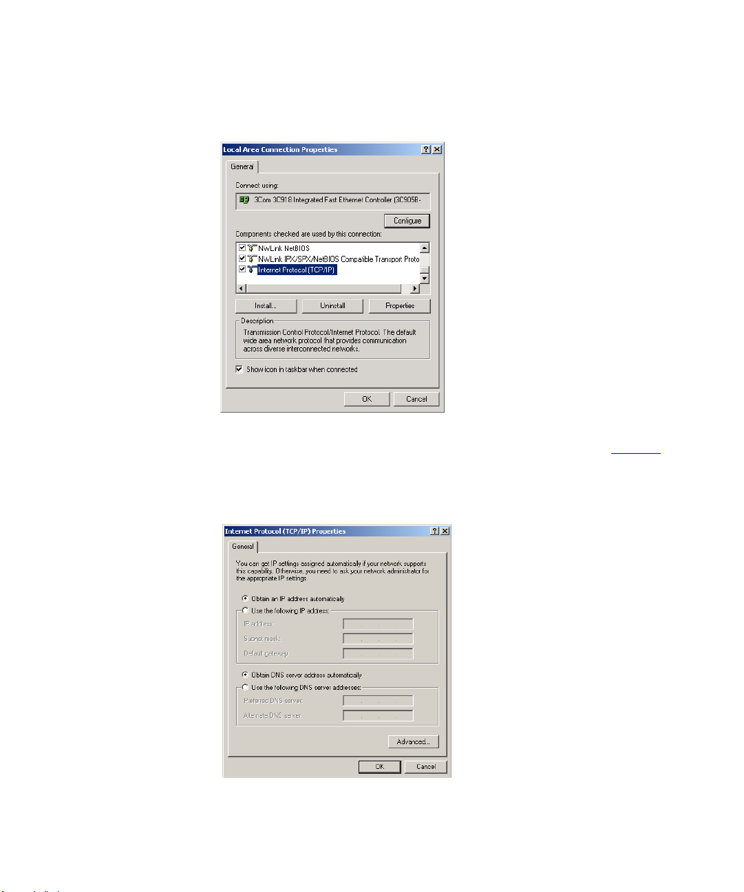
26 CHAPTER 3: SETTING UP YOUR COMPUTERS
Figure 6 Local Area Properties Screen
6 Ensure that the options Obtain an IP Address automatically, and Obtain
DNS server address automatically are both selected as shown in Figure 7
.
Click OK.
Figure 7 Internet Protocol (TCP/IP) Properties Screen
7 Restart your computer.

Obtaining an IP Address Automatically 27
Windows XP If you are using a Windows XP computer, use the following procedure to
change your TCP/IP settings:
1 From the Windows Start menu, select Control Panel.
2 Click on Network and Internet Connections.
3 Click on the Network Connections icon.
4 Double click on LAN or High Speed Connection icon. A screen titled Local
Area Connection Status will appear.
5 Select Internet Protocol TCP/IP and click on Properties.
6 Ensure that the options Obtain an IP Address automatically, and Obtain
DNS servers automatically are both selected. Click OK.
7 Restart your computer.
Windows 95/98/ME If you are using a Windows 95/98/ME computer, use the following
procedure to change your TCP/IP settings:
1 From the Windows Start Menu, select Settings > Control Panel.
2 Double click on Network. Select the TCP/IP item for your network card
and click on Properties.
3 In the TCP/IP dialog, select the IP Address tab, and ensure that Obtain IP
address automatically is selected. Click OK.
Macintosh If you are using a Macintosh computer, use the following procedure to
change your TCP/IP settings:
1 From the desktop, select Apple Menu, Control Panels, and TCP/IP.
2 In the TCP/IP control panel, set Connect Via: to “Ethernet”.
3 In the TCP/IP control panel, set Configure: to “Using DHCP Server.”
4 Close the TCP/IP dialog box, and save your changes.
5 Restart your computer.
28 CHAPTER 3: SETTING UP YOUR COMPUTERS
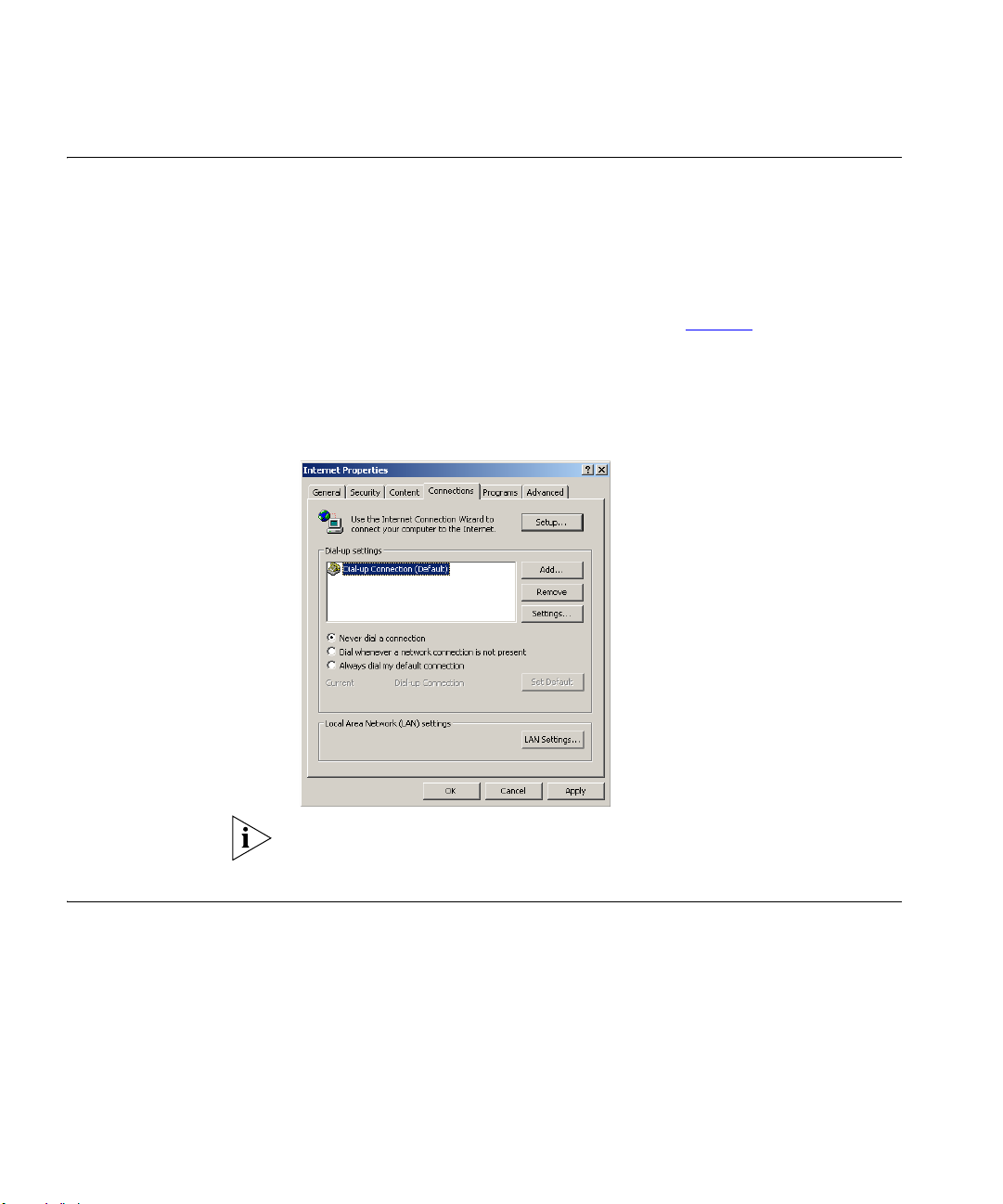
Disabling PPPoE
and PPTP Client
Software
If you have PPPoE or PPTP client software installed on your computer, you
will need to disable it. To do this:
1 From the Windows Start menu, select Settings > Control Panel.
2 Double click on Internet Options.
3 Select the Connections Tab. A screen similar to Figure 8
should be
displayed.
4 Select the Never Dial a Connection option.
Figure 8 Internet Properties Screen
You may wish to remove the PPPoE client software from your computer
to free resources, as it is not required for use with the Router.
Disabling Web
Proxy
Ensure that you do not have a web proxy enabled on your computer.
Go to the Control Panel and click on Internet Options. Select the
Connections tab and click LAN Settings at the bottom. Make sure that
the Use Proxy Server option is unchecked.
4
RUNNING THE SETUP WIZARD
Accessing the
Wizard
The Router setup program is Web-based, which means that it is accessed
through your Web browser (Netscape Navigator 4.7 or higher, Internet
Explorer 5.0 or higher, or Mozilla 1.2.1 or higher).
To use the Setup Wizard:
1 Ensure that you have at least one computer connected to the Router.
Refer to Chapter 2
for details on how to do this.
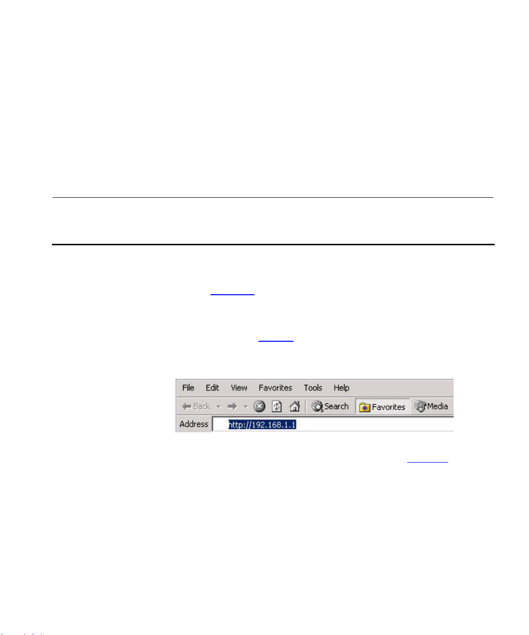
2 Launch your Web browser on the computer.
3 Enter the following URL in the location or address field of your browser:
http://192.168.1.1 (Figure 9
). The Login screen displays.
Figure 9 Web Browser Location Field (Factory Default)
4 To log in as an administrator, enter the password (the default setting is
admin) in the System Password field and click Log in (Figure 10
).
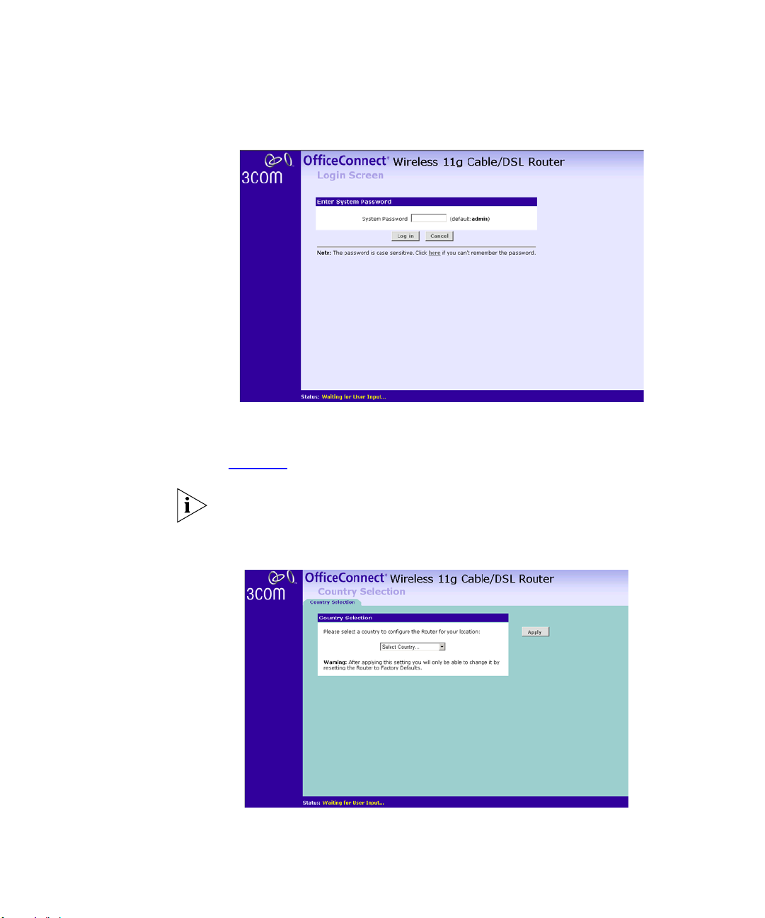
30 CHAPTER 4: RUNNING THE SETUP WIZARD
Figure 10 Router Login Screen
5 If the password is correct, the Country Selection screen will appear. Select
the country you wish to configure the Router for, then click Apply.
(Figure 11
)
If your purchased your Router in the United States, you do not see this
screen, as it is automatically set.
Figure 11 Country Selection Screen
Accessing the Wizard 31
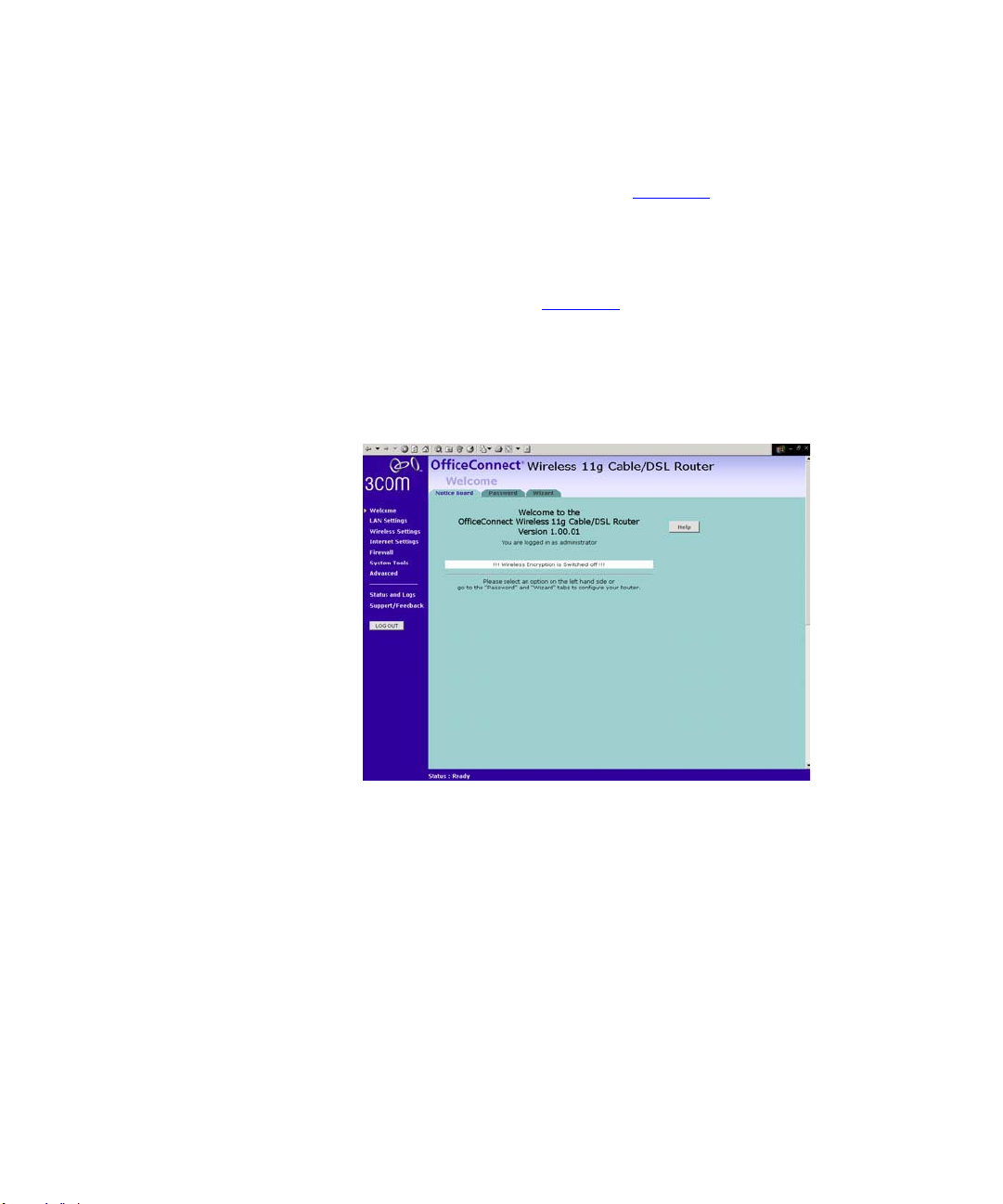
6 When you have selected a country either:
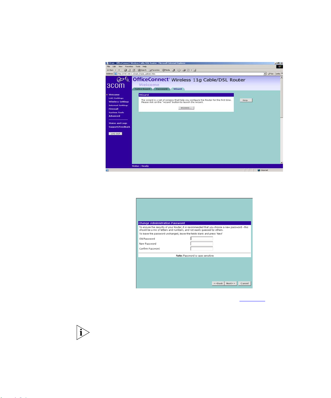
■ The Welcome screen will appear (Figure 12). Select the Wizard tab
and click Wizard.
or
■ If your Router has not been configured before, the Wizard will launch
automatically (refer to Figure 13
).
7 Click Next.
8 You will be guided step by step through a basic setup procedure.
Figure 12 Welcome Screen
32 CHAPTER 4: RUNNING THE SETUP WIZARD
Figure 13 Wizard Screen
Password Figure 14 Change Administration Password Screen
When the Change Administration Password screen (Figure 14) appears,
type the Old Password, then a new password in both the New Password
and Confirm Password boxes.
3Com recommends entering a new password when setting up the Router
for the first time. The Router is shipped from the factory with a default
password, admin.
1. Password is case sensitive.
Accessing the Wizard 33
2. Write the new password down and keep it in a safe place, so that you
can change your settings in the future.
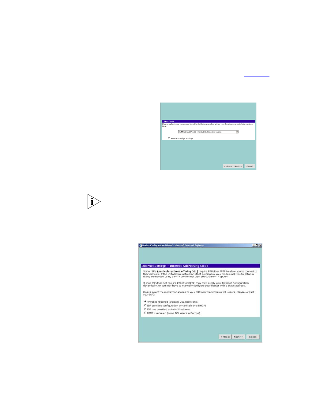
Click Next to display the Time Zone setup screen (Figure 15
).
Time Zone
Figure 15 Time Zone Screen
Select your time zone from the pull-down menu, check the daylight
savings option if required, and then click Next.
The Daylight Savings option advances the system clock by one hour. It
does not cause the system clock to be updated for daylight savings time
automatically.
WAN Settings
Figure 16 Internet Settings Screen
This Internet Addressing Mode window allows you to set up the Router
for the type of Internet connection you have. Before setting up your
34 CHAPTER 4: RUNNING THE SETUP WIZARD
Internet connection mode, have the modem setting information from
your ISP ready.
Select an Internet Addressing mode from the following:
■ PPPoE is required (typically DSL users only)
■ ISP provides configuration dynamically (via DHCP)
■ ISP has provided a static IP address
■ PPTP is required (some DSL users in Europe)
and click Next.
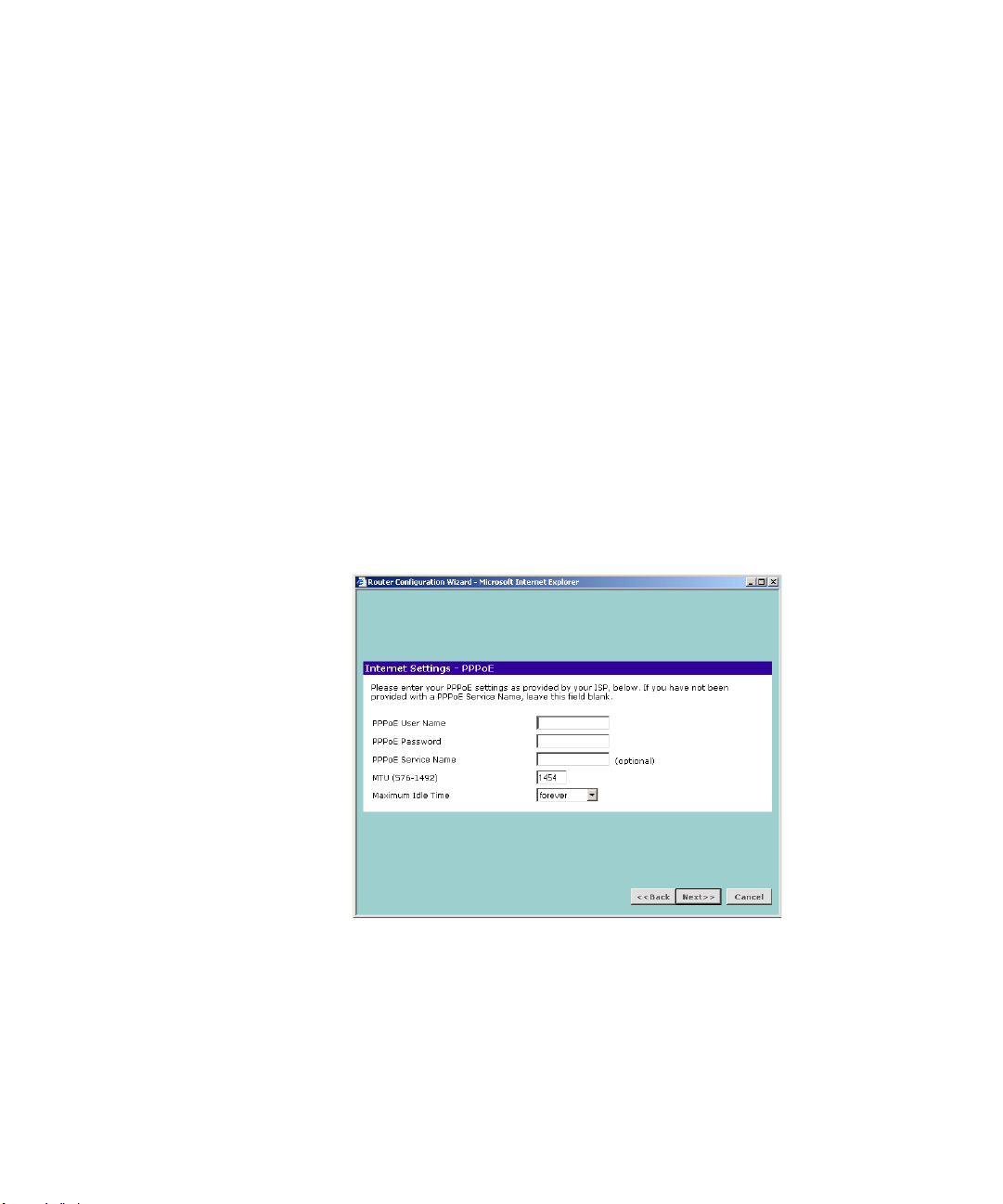
PPPoE Mode
Figure 17 PPPoE Screen
To setup the Router for use with a PPP over Ethernet (PPPoE) connection,
use the following procedure:
1 Enter your PPP over Ethernet user name in the PPPoE User Name text box.
2 Enter your PPP over Ethernet password in the PPPoE Password text box.!
3 Enter your PPP over Ethernet service name in the PPPoE Service Name text
box.
Accessing the Wizard 35
Do not enter anything in this box if your ISP does not require a service
name.
4 Enter the MTU value supplied by your ISP in the MTU text box. If your ISP
has not supplied an MTU value, leave this at the default value. The
default is 1454.
5 Select an idle time from the Maximum Idle Time drop down list. This is
the amount of time without Internet activity that you want to allow
before the Router ends the PPPoE session.
6 Check all of your settings, and then click Next.
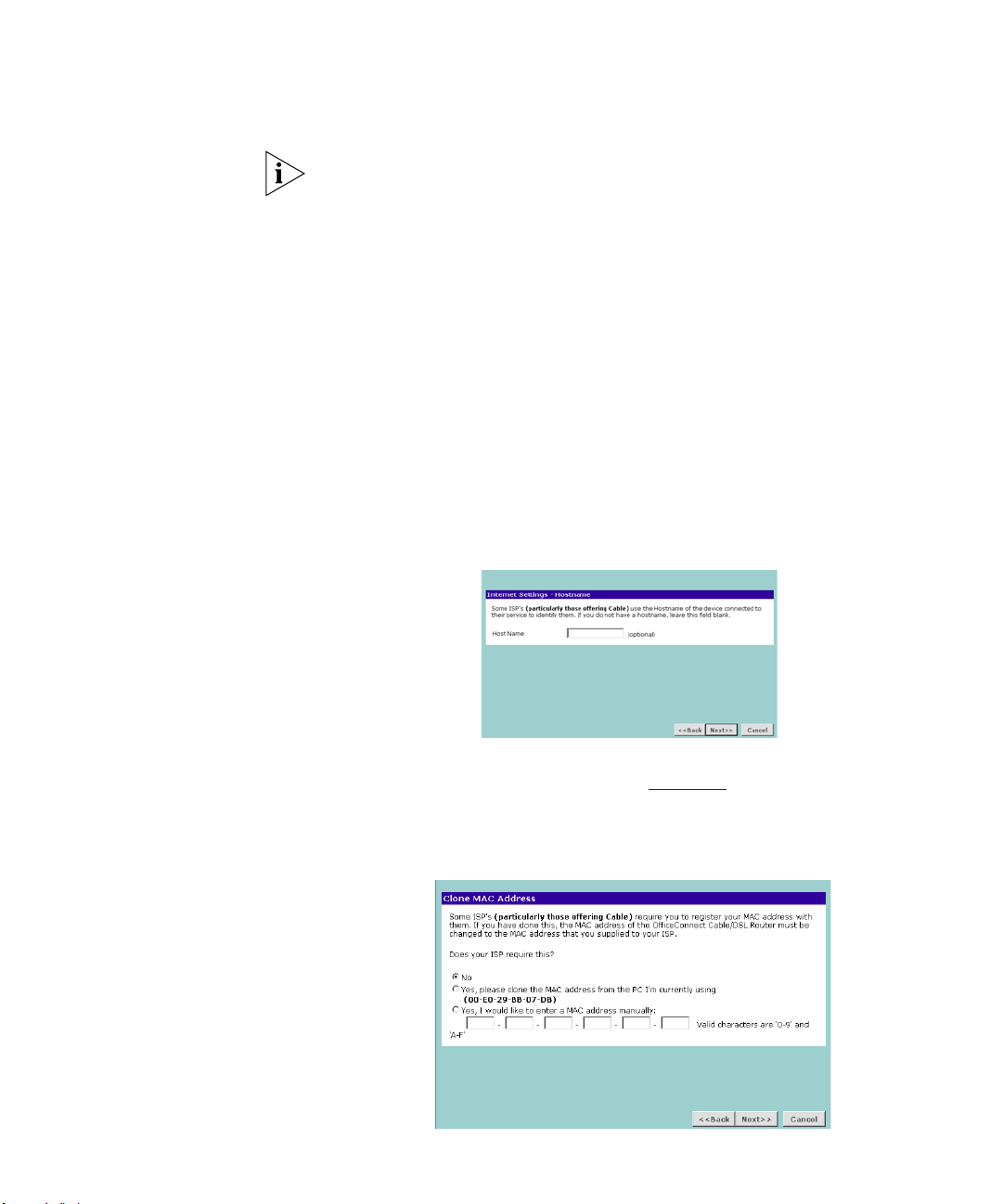
Dynamic IP Address Mode
To setup the Router for use with a dynamic IP address connection:
1 Select the ISP provides configuration dynamically (via DHCP) and then
click Next.
Figure 18 Hostname Screen
2 Some ISPs require a host name. If your ISP has this requirement, enter the
host name in the Host Name text box (Figure 18
) and click Next. The
Clone MAC Address screen displays.
Figure 19 Clone MAC Address Screen
36 CHAPTER 4: RUNNING THE SETUP WIZARD
3 If your ISP requires an assigned MAC address, select Yes, I would like to
enter a MAC address manually and enter the values for a MAC address if
required (Figure 19
). If the computer you are now using is the one that
was previously connected directly to the cable modem, choose Yes ,
please clone the MAC address from the PC I’m currently using.
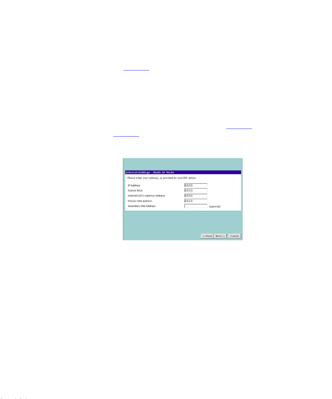
Static IP Mode
To setup the Router for use with a static IP address connection, use the
following procedure:
1 Select ISP has provided a static IP address, (see Figure 16
) and then click
Next. Figure 20
displays.
Figure 20 Static IP Mode Screen
2 Enter your IP Address in the IP Address text box.
3 Enter your subnet mask in the Subnet Mask text box.
4 Enter your ISP Router address in the Internet (ISP) Gateway Address text
box.
5 Enter your primary DNS address in the Primary DNS Address text box.
6 Enter your secondary DNS address in the Secondary DNS Address text
box.
This step is optional. Not all ISPs require a secondary DNS address.
7 Check all of your settings, and then click Next.
Accessing the Wizard 37
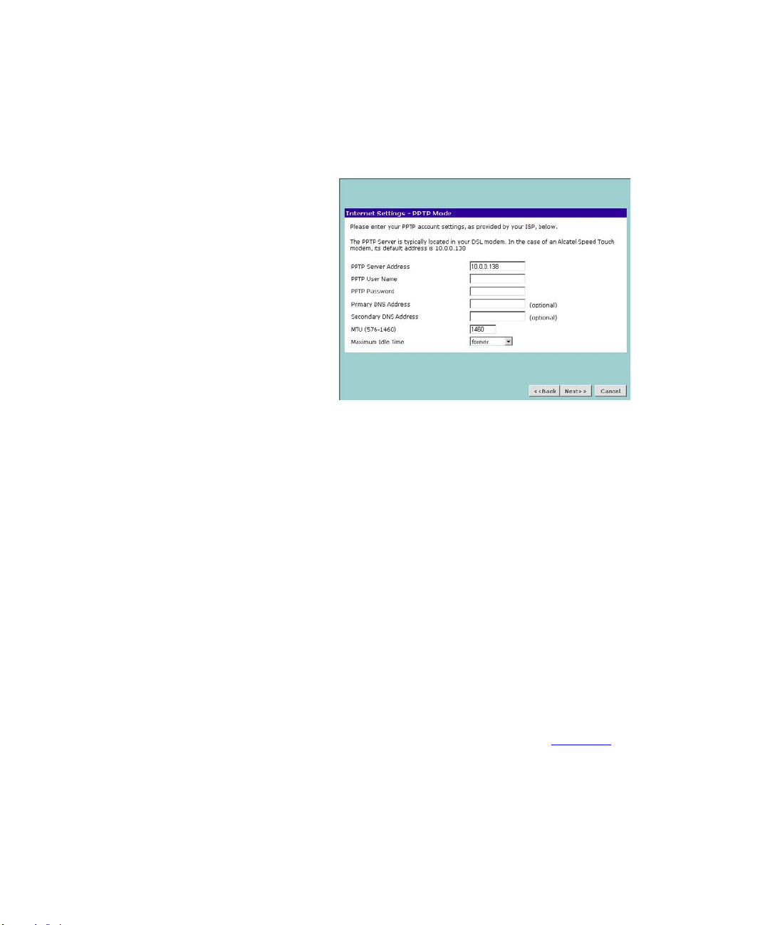
PPTP Mode
Figure 21 PPTP Mode Screen
To setup the Router for use with a PPTP connection, use the following
procedure:
1 Enter your PPTP server address in the PPTP Server Address text box.
2 Enter your PPTP user name in the PPTP User Name text box.
3 Enter your PPTP password in the PPTP Password text box.
4 Enter your Primary DNS Address and Secondary DNS address.
Your ISP may provide you with primary and secondary DNS addresses. If
they have been provided, enter the addresses in the appropriate text
boxes. If not, leave 0.0.0.0 in the boxes.
5 Enter the value supplied by your ISP in the MTU text box. If your ISP has
not supplied an MTU value, leave this at the default value. The default is
1460.
6 Select an idle time from the Maximum Idle Time drop-down list. This is
the amount of time without Internet activity that you want to allow
before the Router ends the PPTP session.
7 Check all of your settings, and then click Next. Figure 22
displays.
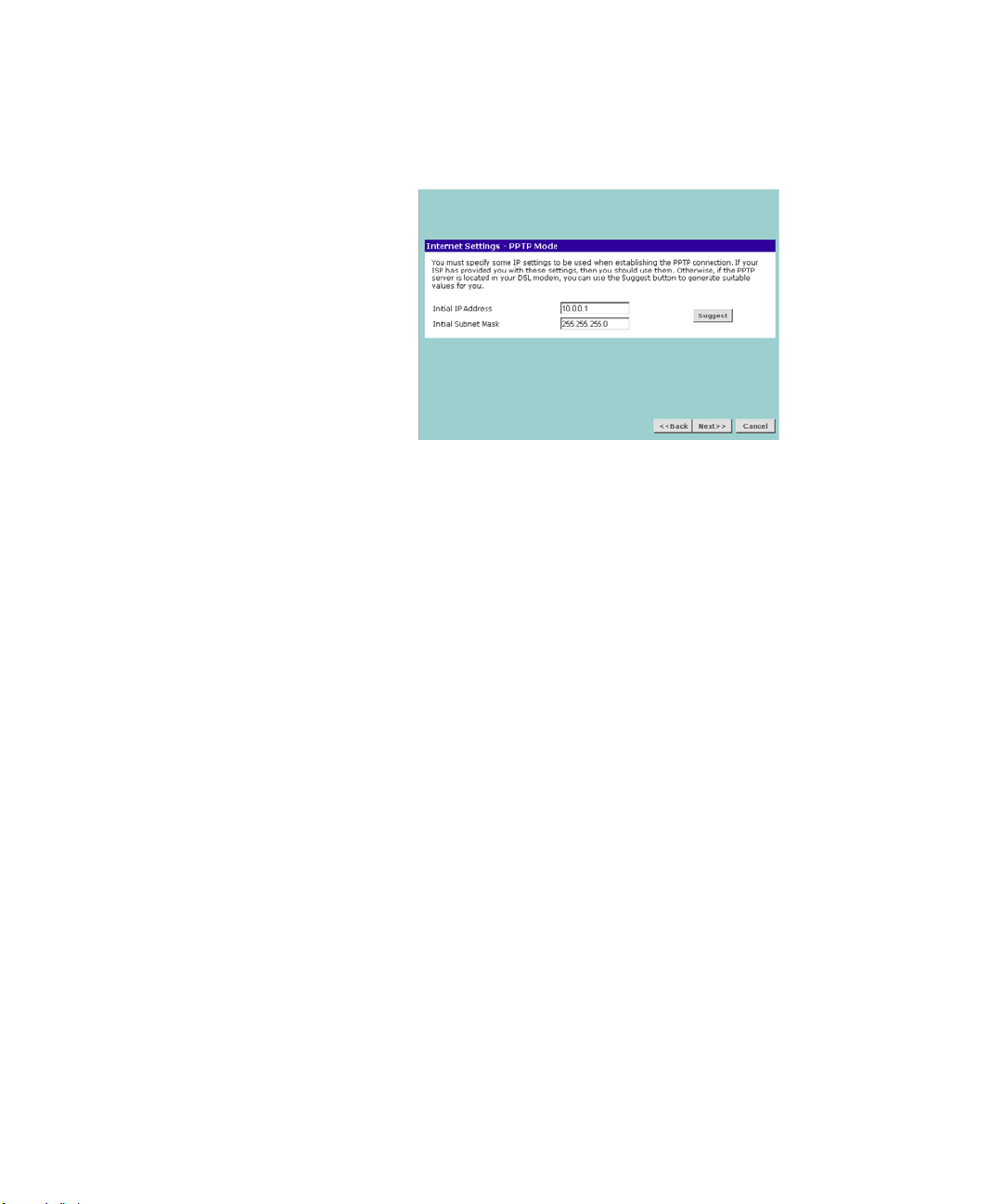
38 CHAPTER 4: RUNNING THE SETUP WIZARD
Figure 22 PPTP IP Settings
8 IP settings must be used when establishing a PPTP connection. Fill in the
Initial IP Address and the Initial Subnet Mask fields if your ISP has
provided you with these settings. Alternatively, if the PPTP server is
located in your DSL modem, click Suggest to select an IP address on the
same subnet as the PPTP server.
Accessing the Wizard 39
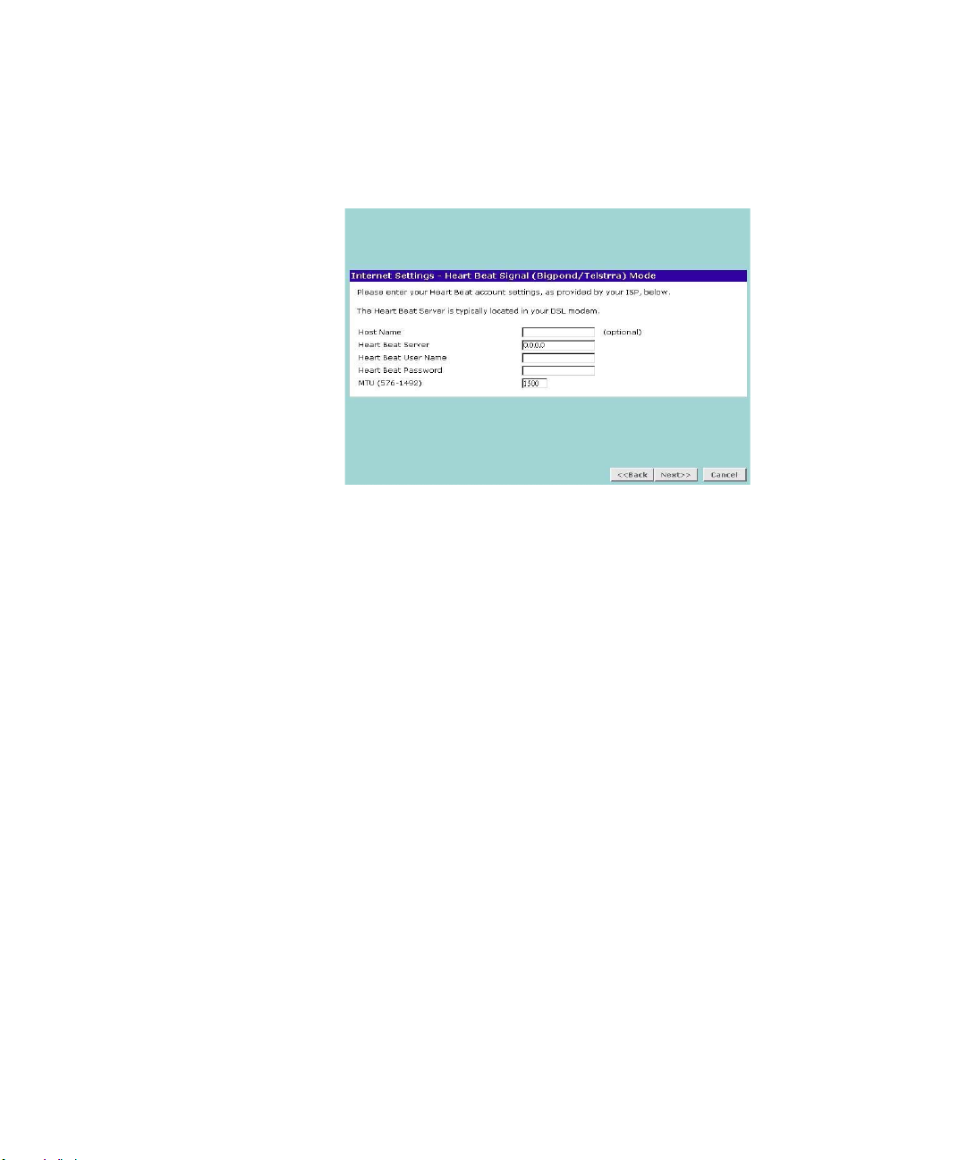
Heart Beat Signal Mode(For Australia only)
Figure 23 Heart Beat Signal Mode Screen
To set up the Router for use with an L2TP connection, use the following
procedure:
1 IT is a service used in Australia only. If you are using Heart Beat Signal
connection, check with your ISP for the necessary setup information.
2 Enter the User Name and Password you use when logging nonto your ISP
through a Heart Beat connection.
40 CHAPTER 4: RUNNING THE SETUP WIZARD
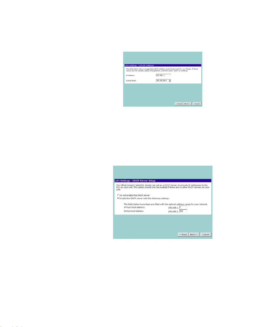
LAN Settings Figure 24 LAN IP Address Screen
This screen displays a suggested LAN IP address and subnet mask of the
Router. It also allows you to change the IP address and subnet mask.
DHCP The Router contains a Dynamic Host Configuration (DHCP) server that
can automatically configure the TCP/IP settings of every computer on
your network.
Figure 25 DHCP Server Setup Screen
To activate the DHCP Server option, select Enable the DHCP server with
the following settings: and specify the IP pool range. The largest available
continuous IP pool will be automatically entered; if this is not appropriate,
make your required changes. To disable DHCP, select Do not enable the
DHCP server. Click Next when you have finished.
Accessing the Wizard 41
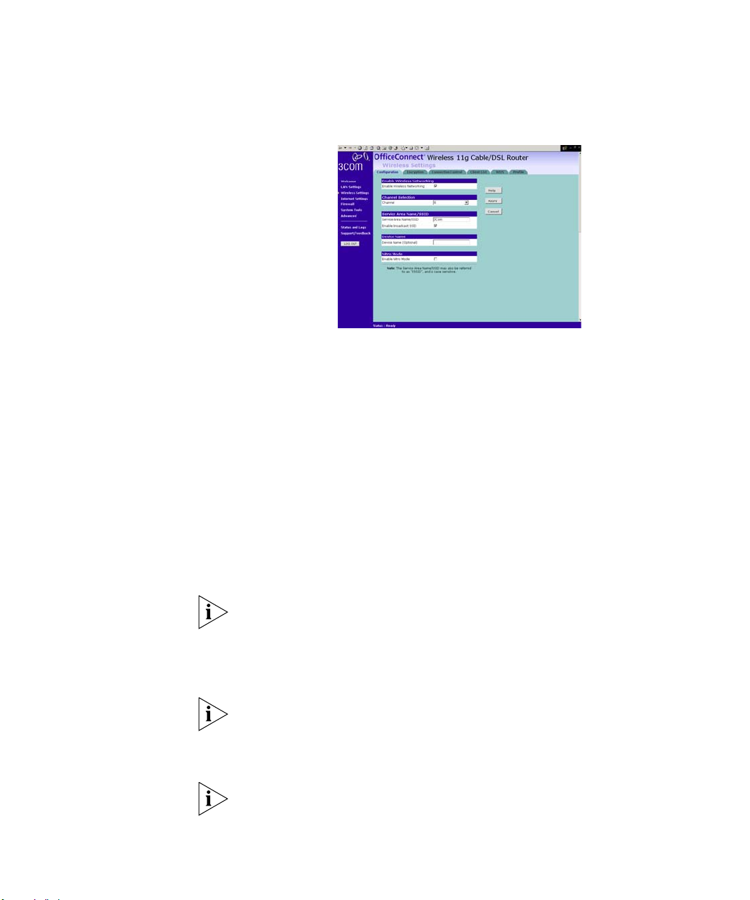
Wireless Settings Figure 26 Wireless Configuration Screen
This screen displays the Channel and Service Area Name. It also allows
you to change these settings. There are a maximum of 14 channels, the
number available to you is dependent on the country you reside in.
Selecting Clear Channel Select from the Channel drop-down list allows
the Router to automatically select an available channel when first
powered on.
The Service Area Name default for 3Com products is “3Com”. Up to 32
(case sensitive) characters can be entered for the Service Area Name.
3Com strongly recommends that you change the SSID to something
other than the default.
Click Next when you have finished.
If you are configuring the Router from a wireless computer any changes
you make to the wireless configuration will result in communication
between the Router and your computer being lost. This is why 3Com
strongly recommends that you configure the Router from a wired
computer.
It is very important that you set up your wireless clients to use the same
Service Area Name or SSID as the one you use on this screen. If your
clients use a different Service Area Name then they will not be able to
communicate with the Router.
The choice of channel is less important as Clients will generally search all
of the available channels. You should however make a note of the
42 CHAPTER 4: RUNNING THE SETUP WIZARD
channel you select as this may be useful if you experience problems with
your clients.
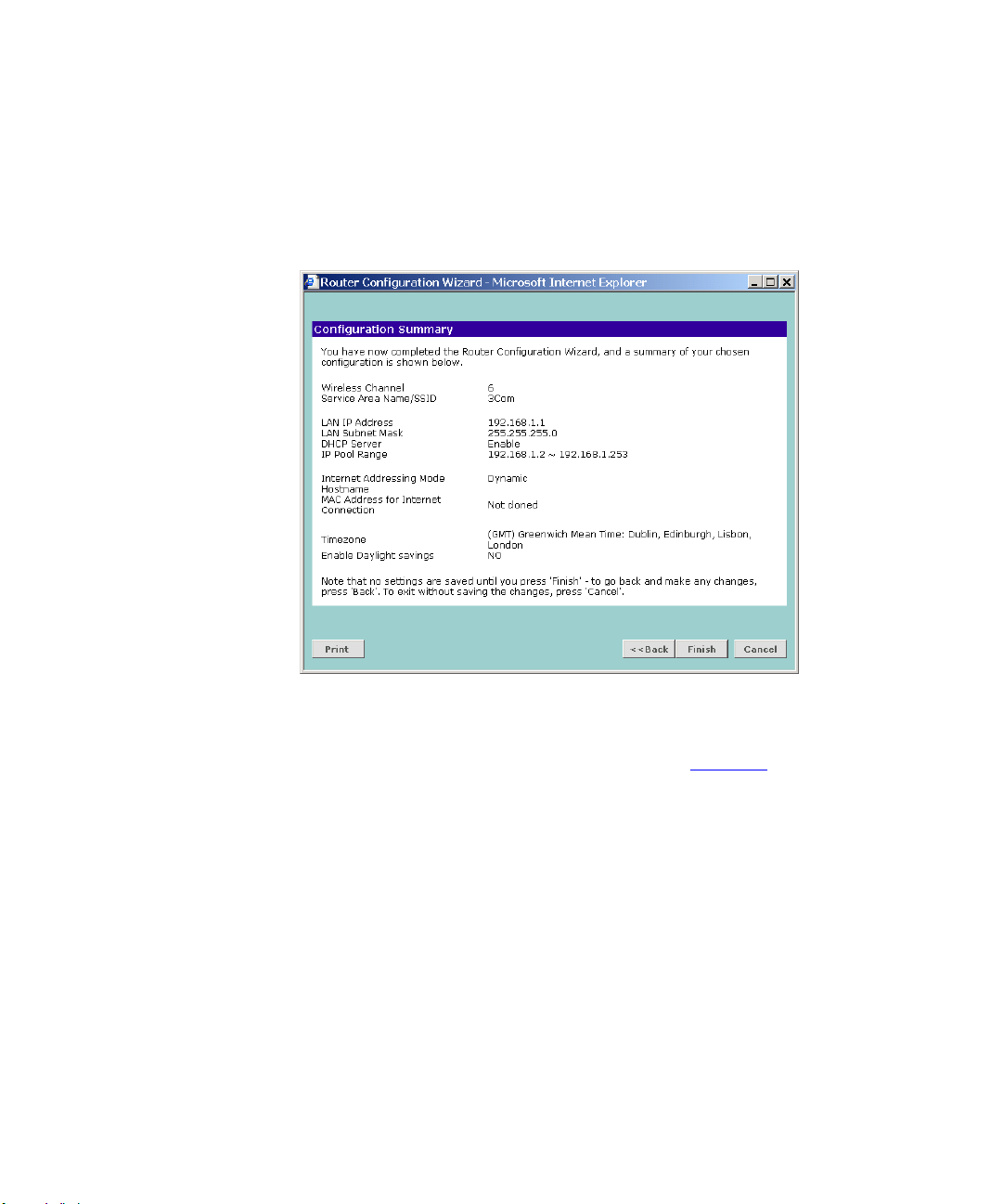
Summary Figure 27 Configuration Summary Screen
When you complete the Setup Wizard, a configuration summary will
display. 3Com recommends that you verify the configuration information
of the Router and then print this page for your records. Click Finish to
display the Wizard completed screen, shown in Figure 28
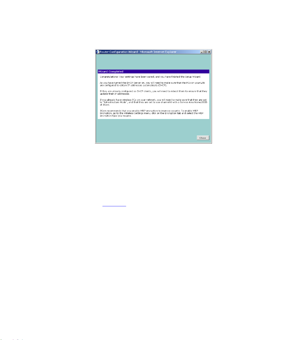
Accessing the Wizard 43
Figure 28 Wizard Completed Screen
If you have made changes to the LAN Settings or wireless configuration
options, you may need to reconfigure the computer you are using in
order to make contact with the Router again.
Your Router is now configured and ready for use.
See Chapter 5
for a detailed description of the Router configuration
screens.
 Loading…